JP4843621B2 - Apparatus for supplying fresh air to a turbocharged piston internal combustion engine and method of operating the apparatus - Google Patents
Apparatus for supplying fresh air to a turbocharged piston internal combustion engine and method of operating the apparatus Download PDFInfo
- Publication number
- JP4843621B2 JP4843621B2 JP2007556563A JP2007556563A JP4843621B2 JP 4843621 B2 JP4843621 B2 JP 4843621B2 JP 2007556563 A JP2007556563 A JP 2007556563A JP 2007556563 A JP2007556563 A JP 2007556563A JP 4843621 B2 JP4843621 B2 JP 4843621B2
- Authority
- JP
- Japan
- Prior art keywords
- flap
- control unit
- electronic control
- air
- compressed air
- Prior art date
- Legal status (The legal status is an assumption and is not a legal conclusion. Google has not performed a legal analysis and makes no representation as to the accuracy of the status listed.)
- Expired - Fee Related
Links
Images


Classifications
-
- F—MECHANICAL ENGINEERING; LIGHTING; HEATING; WEAPONS; BLASTING
- F02—COMBUSTION ENGINES; HOT-GAS OR COMBUSTION-PRODUCT ENGINE PLANTS
- F02D—CONTROLLING COMBUSTION ENGINES
- F02D41/00—Electrical control of supply of combustible mixture or its constituents
- F02D41/0002—Controlling intake air
- F02D41/0007—Controlling intake air for control of turbo-charged or super-charged engines
-
- F—MECHANICAL ENGINEERING; LIGHTING; HEATING; WEAPONS; BLASTING
- F02—COMBUSTION ENGINES; HOT-GAS OR COMBUSTION-PRODUCT ENGINE PLANTS
- F02B—INTERNAL-COMBUSTION PISTON ENGINES; COMBUSTION ENGINES IN GENERAL
- F02B21/00—Engines characterised by air-storage chambers
-
- F—MECHANICAL ENGINEERING; LIGHTING; HEATING; WEAPONS; BLASTING
- F02—COMBUSTION ENGINES; HOT-GAS OR COMBUSTION-PRODUCT ENGINE PLANTS
- F02B—INTERNAL-COMBUSTION PISTON ENGINES; COMBUSTION ENGINES IN GENERAL
- F02B33/00—Engines characterised by provision of pumps for charging or scavenging
- F02B33/44—Passages conducting the charge from the pump to the engine inlet, e.g. reservoirs
-
- F—MECHANICAL ENGINEERING; LIGHTING; HEATING; WEAPONS; BLASTING
- F02—COMBUSTION ENGINES; HOT-GAS OR COMBUSTION-PRODUCT ENGINE PLANTS
- F02B—INTERNAL-COMBUSTION PISTON ENGINES; COMBUSTION ENGINES IN GENERAL
- F02B37/00—Engines characterised by provision of pumps driven at least for part of the time by exhaust
- F02B37/04—Engines with exhaust drive and other drive of pumps, e.g. with exhaust-driven pump and mechanically-driven second pump
-
- F—MECHANICAL ENGINEERING; LIGHTING; HEATING; WEAPONS; BLASTING
- F02—COMBUSTION ENGINES; HOT-GAS OR COMBUSTION-PRODUCT ENGINE PLANTS
- F02D—CONTROLLING COMBUSTION ENGINES
- F02D9/00—Controlling engines by throttling air or fuel-and-air induction conduits or exhaust conduits
- F02D9/02—Controlling engines by throttling air or fuel-and-air induction conduits or exhaust conduits concerning induction conduits
-
- F—MECHANICAL ENGINEERING; LIGHTING; HEATING; WEAPONS; BLASTING
- F02—COMBUSTION ENGINES; HOT-GAS OR COMBUSTION-PRODUCT ENGINE PLANTS
- F02D—CONTROLLING COMBUSTION ENGINES
- F02D9/00—Controlling engines by throttling air or fuel-and-air induction conduits or exhaust conduits
- F02D9/08—Throttle valves specially adapted therefor; Arrangements of such valves in conduits
- F02D9/10—Throttle valves specially adapted therefor; Arrangements of such valves in conduits having pivotally-mounted flaps
- F02D9/1035—Details of the valve housing
-
- B—PERFORMING OPERATIONS; TRANSPORTING
- B60—VEHICLES IN GENERAL
- B60W—CONJOINT CONTROL OF VEHICLE SUB-UNITS OF DIFFERENT TYPE OR DIFFERENT FUNCTION; CONTROL SYSTEMS SPECIALLY ADAPTED FOR HYBRID VEHICLES; ROAD VEHICLE DRIVE CONTROL SYSTEMS FOR PURPOSES NOT RELATED TO THE CONTROL OF A PARTICULAR SUB-UNIT
- B60W2540/00—Input parameters relating to occupants
- B60W2540/10—Accelerator pedal position
- B60W2540/106—Rate of change
-
- B—PERFORMING OPERATIONS; TRANSPORTING
- B60—VEHICLES IN GENERAL
- B60W—CONJOINT CONTROL OF VEHICLE SUB-UNITS OF DIFFERENT TYPE OR DIFFERENT FUNCTION; CONTROL SYSTEMS SPECIALLY ADAPTED FOR HYBRID VEHICLES; ROAD VEHICLE DRIVE CONTROL SYSTEMS FOR PURPOSES NOT RELATED TO THE CONTROL OF A PARTICULAR SUB-UNIT
- B60W2540/00—Input parameters relating to occupants
- B60W2540/30—Driving style
-
- F—MECHANICAL ENGINEERING; LIGHTING; HEATING; WEAPONS; BLASTING
- F02—COMBUSTION ENGINES; HOT-GAS OR COMBUSTION-PRODUCT ENGINE PLANTS
- F02B—INTERNAL-COMBUSTION PISTON ENGINES; COMBUSTION ENGINES IN GENERAL
- F02B29/00—Engines characterised by provision for charging or scavenging not provided for in groups F02B25/00, F02B27/00 or F02B33/00 - F02B39/00; Details thereof
- F02B29/04—Cooling of air intake supply
- F02B29/0406—Layout of the intake air cooling or coolant circuit
-
- F—MECHANICAL ENGINEERING; LIGHTING; HEATING; WEAPONS; BLASTING
- F02—COMBUSTION ENGINES; HOT-GAS OR COMBUSTION-PRODUCT ENGINE PLANTS
- F02D—CONTROLLING COMBUSTION ENGINES
- F02D2200/00—Input parameters for engine control
- F02D2200/02—Input parameters for engine control the parameters being related to the engine
- F02D2200/04—Engine intake system parameters
- F02D2200/0406—Intake manifold pressure
-
- F—MECHANICAL ENGINEERING; LIGHTING; HEATING; WEAPONS; BLASTING
- F02—COMBUSTION ENGINES; HOT-GAS OR COMBUSTION-PRODUCT ENGINE PLANTS
- F02D—CONTROLLING COMBUSTION ENGINES
- F02D2200/00—Input parameters for engine control
- F02D2200/60—Input parameters for engine control said parameters being related to the driver demands or status
- F02D2200/606—Driving style, e.g. sporty or economic driving
-
- Y—GENERAL TAGGING OF NEW TECHNOLOGICAL DEVELOPMENTS; GENERAL TAGGING OF CROSS-SECTIONAL TECHNOLOGIES SPANNING OVER SEVERAL SECTIONS OF THE IPC; TECHNICAL SUBJECTS COVERED BY FORMER USPC CROSS-REFERENCE ART COLLECTIONS [XRACs] AND DIGESTS
- Y02—TECHNOLOGIES OR APPLICATIONS FOR MITIGATION OR ADAPTATION AGAINST CLIMATE CHANGE
- Y02T—CLIMATE CHANGE MITIGATION TECHNOLOGIES RELATED TO TRANSPORTATION
- Y02T10/00—Road transport of goods or passengers
- Y02T10/10—Internal combustion engine [ICE] based vehicles
- Y02T10/12—Improving ICE efficiencies
Abstract
Description
本発明は、ターボ過給式のピストン内燃機関に新空気(フレッシュエア)を供給するための装置であって、吸気管として新ガス管路区分が設けられており、該新ガス管路区分が、調節可能なバタフライもしくはフラップと、流入のための第1の端接続部と、流出のための第2の端接続部とを有しており、第1の端接続部と第2の端接続部との間で管状の壁に、前記調節可能なフラップのための旋回可能に支承されたシャフトが設けられており、前記調節可能なフラップが、調節のために調節装置に結合されており、前記調節可能なフラップと第2の端接続部との間で、圧縮空気接続部が開口を持って管状の内室に開口している形式のものに関する。 The present invention is an apparatus for supplying new air (fresh air) to a turbocharged piston internal combustion engine, wherein a new gas pipe section is provided as an intake pipe, and the new gas pipe section is , Having an adjustable butterfly or flap, a first end connection for inflow, and a second end connection for outflow, the first end connection and the second end connection A pivotable bearing shaft for the adjustable flap is provided on the tubular wall between the parts, the adjustable flap being coupled to an adjusting device for adjustment; Between the adjustable flap and the second end connection, the compressed air connection has an opening into the tubular inner chamber.
さらに、本発明はこのような形式の装置を運転する方法にも関する。 The invention further relates to a method of operating such a device.
ターボ過給を行うピストン内燃機関のよく知られている特性は、車両においてアクセルが踏み込まれた際にターボ過給式のピストン内燃機関が、ある程度の遅延を持ってしか反応しないことである。なぜならば、ターボチャージャは提供された空気量を緩慢に高めることしかできないからである。このことはトルク経過におけるターボラグとして知られている。 A well-known characteristic of a piston internal combustion engine that performs turbocharging is that the turbocharged piston internal combustion engine reacts only with a certain delay when the accelerator is depressed in the vehicle. This is because turbochargers can only slowly increase the amount of air provided. This is known as a turbo lag over the course of torque.
ドイツ連邦共和国特許第3906312号明細書には、ターボラグを縮小もしくは短縮させるための方法および構成が開示されている。この場合、ディーゼルエンジンの加速時に圧縮空気アキュムレータから規定の空気量が吸気管内に吹き込まれ、そしてこれに合わせて燃料噴射量が適合される。ターボ過給式のディーゼルエンジンはオートマティック変速機と圧縮空気ブレーキ装置とを備えた市街地走行バス(路線バス)のために特に適している。市街地走行バスは、決められた走行サイクルを実行する。この場合、ディーゼルエンジンの負荷および回転数過程は正確に予想され得るので、吹込み時間および空気量を予め決定することができる。これとは全く異なる条件が生じるのが、長距離走行交通において使用される実用車の場合である。実用車は規則的な走行サイクルに従って走行するわけではなく、有効荷重は広い範囲の間で変動し、運転者の走行形態にも、大きな多種多様性が認められる。上記の構成および方法によっても、このような問題を取り除くことはできない。
Patent Abstracts of Japan、Bd.1995、Nr07、1995年8月31日もしくは特開平7−91267号公報に基づき、吸込管として新空気管路区分を備えたターボ過給式のピストン内燃機関に新空気を供給するための装置が開示されている。この場合にも、フラップが調節装置に連結されている。しかし、この公知の装置では、ブレーキシステム等のような別のユニットのためにも圧縮空気アキュムレータ内にいつでも十分な圧縮空気が残ることが保証されていない。
German Patent 3,906,312 discloses a method and arrangement for reducing or shortening turbo lag. In this case, a specified amount of air is blown into the intake pipe from the compressed air accumulator during acceleration of the diesel engine, and the fuel injection amount is adapted accordingly. The turbocharged diesel engine is particularly suitable for city buses (route buses) equipped with an automatic transmission and a compressed air brake device. The city driving bus executes a predetermined driving cycle. In this case, since the load and the rotational speed process of the diesel engine can be accurately predicted, the blowing time and the air amount can be determined in advance. A completely different condition occurs in the case of a practical vehicle used in long-distance travel traffic. Practical vehicles do not travel according to a regular driving cycle, the effective load varies between a wide range, and a great variety of driving modes are recognized. Even with the above-described configuration and method, such a problem cannot be eliminated.
Patent Abstracts of Japan, Bd. 1995, Nr07, August 31, 1995 or Japanese Patent Application Laid-Open No. 7-91267, an apparatus for supplying new air to a turbocharged piston internal combustion engine having a new air pipe section as a suction pipe It is disclosed. Again, the flap is connected to the adjusting device. However, this known device does not guarantee that sufficient compressed air will remain in the compressed air accumulator at any time for other units such as brake systems.
本発明の課題は、冒頭で述べた形式の装置を改良して、空気吹込みを走行形態と車両の有効荷重とに適合させることができ、しかも当該装置が組付けユニットとしてディーゼルエンジンの種々の新ガス管路システムに組み付けられ得るような装置を提供することである。さらに本発明の課題は、このような装置を運転するために適した方法を提供することである。 The object of the present invention is to improve the device of the type mentioned at the outset so that the air blowing can be adapted to the driving mode and the effective load of the vehicle, and the device as an assembly unit for various types of diesel engines. It is to provide an apparatus that can be assembled into a new gas line system. It is a further object of the present invention to provide a method suitable for operating such a device.
この課題は、請求項1の上位概念部に記載の形式の装置において、請求項1の特徴部に記載の特徴、つまり圧縮空気接続部が、遮断された位置と、任意に開かれた位置とを備えた弁を有する量制御装置と協働するようになっており、該量制御装置が、電気的な入力部を介して制御可能であり、該電気的な入力部が、電子制御ユニットの接続部に接続されており、しかもフラップの調節装置は、前記量制御装置および/または電子制御ユニットによって、フラップの完全に開かれた位置に対して、前記量制御装置の完全に遮断された位置が対応するように強制操作されていることにより解決される。 The object is to provide an apparatus of the type described in the superordinate conceptual part of claim 1, wherein the feature according to claim 1, that is, the position where the compressed air connection part is shut off and the position where it is opened arbitrarily. And a quantity control device having a valve comprising: the quantity control device is controllable via an electrical input, the electrical input being connected to the electronic control unit. A flap adjustment device connected to the connection, and the position of the amount control device being completely interrupted by the amount control device and / or the electronic control unit relative to the position of the flap fully open. Is solved by being forced to respond.
方法技術的には、上記課題は請求項5に記載の方法、つまり上記装置に圧縮空気アキュムレータを装備させ、該圧縮空気アキュムレータ内に、エンジンシリンダの新ガス管路区分内への制御された一時的な吹込みのための圧縮空気を蓄える形式の、車両−ピストン内燃機関、特にターボ過給を有するディーゼルエンジンの加速・エミッション特性を改善する方法において、以下の方法ステップ:
−トルク要求信号を求めて、データを電子制御ユニットに供給し、
−エンジン特性値を求めて、該特性値を電子制御ユニットに供給し、
−シリンダ吸気弁とフラップとの間の吸気管路の内室内の空気圧を求めて、圧力値を電子制御ユニットに供給し、かつフラップとターボコンプレッサとの間の吸気管路の内室内の空気圧を求めて、圧力値を電子制御ユニットに供給し、
−新ガス管路区分内への一時的な吹込みの弁の開閉を行うと同時に、吹込みの開始時における閉鎖方向へのフラップの操作と、吹込み終了時における開放方向へのフラップの操作とを行うための操作−出力信号を形成するために、前で挙げたデータおよび測定値を電子制御ユニットで処理する、
を実施することを特徴とする、車両−ピストン内燃機関の加速・エミッション特性を改善する方法により解決される。
Technically, the object is to provide a method according to claim 5, i.e. the apparatus is equipped with a compressed air accumulator, in which a controlled temporary entry into a new gas line section of the engine cylinder is provided. In a method for improving the acceleration and emission characteristics of a vehicle-piston internal combustion engine, in particular a diesel engine with turbocharging, in the form of storing compressed air for typical blowing, the following method steps:
-Obtaining a torque request signal and supplying data to the electronic control unit;
-Determining the engine characteristic value and supplying it to the electronic control unit;
-Determine the air pressure inside the intake pipe line between the cylinder intake valve and the flap, supply the pressure value to the electronic control unit, and change the air pressure inside the intake pipe line between the flap and the turbo compressor. Find the pressure value and supply it to the electronic control unit,
-Open and close the valve for temporary blowing into the new gas line section, and simultaneously operate the flap in the closing direction at the start of blowing and the flap in the opening direction at the end of blowing. To process the data and measured values listed above in an electronic control unit to form an output signal,
This is solved by a method for improving acceleration / emission characteristics of a vehicle-piston internal combustion engine.
請求項2〜請求項4ならびに請求項6以下には、本発明の有利な改良形が記載されている。 Claims 2 to 4 and claims 6 and below describe advantageous refinements of the invention.
本発明の利点は、新ガス管路に設けられたスロットルバルブのバタフライもしくはフラップが電子的に制御されて操作され、つまり冒頭で述べた公知先行技術におけるように新ガス圧力により自動的に操作されるだけではないこと、そしてこの操作が電子制御ユニットにより求められ、しかも新ガス圧力および有利にはエンジンパラメータに関連して電子的に処理されることから得られる。 The advantage of the present invention is that the butterfly or flap of the throttle valve provided in the new gas line is operated electronically, that is, automatically operated by the new gas pressure as in the prior art described at the beginning. And this operation is obtained by the electronic control unit and is processed electronically in relation to the new gas pressure and preferably to the engine parameters.
本発明によれば、圧縮空気接続部が量制御装置を備えている。この量制御装置は弁を有しており、この弁は遮断された位置と、任意に開かれた位置とを有している。量制御装置はさらに電気的/電子的な入力部を有しており、この入力部は電子制御ユニットの出力部に接続されている。この場合、電子制御ユニットの第2の出力部には、フラップの調節装置の入力部が接続されているので、フラップの完全に開かれた位置に対して量制御装置の完全に遮断された位置が対応している。 According to the invention, the compressed air connection is provided with a quantity control device. The quantity control device has a valve, which has a closed position and an arbitrarily open position. The quantity control device further has an electrical / electronic input, which is connected to the output of the electronic control unit. In this case, since the input part of the flap adjusting device is connected to the second output part of the electronic control unit, the position where the quantity control device is completely cut off relative to the fully opened position of the flap. Corresponds.
電子制御ユニットの入力部には、以下に挙げる出力部が接続されていると有利である:
フラップと流入のための第1の端接続部との間で管状の内室に配置されている圧力計もしくは圧力測定器を備えた第1の圧力センサもしくは第1の圧力フィーラの出力部;フラップと流出のための第2の端接続部との間で管状の内室に配置されている圧力計もしくは圧力測定器を備えた第2の圧力センサもしくは第2の圧力フィーラの出力部。
The output of the following is advantageously connected to the input of the electronic control unit:
The output of the first pressure sensor or the first pressure feeler with a pressure gauge or pressure measuring device arranged in a tubular inner chamber between the flap and the first end connection for inflow; A second pressure sensor or a second pressure feeler comprising a pressure gauge or a pressure measuring device arranged in a tubular inner chamber between the second end connection for discharge and the second end connection.
本発明の有利な構成では、電子制御ユニットにおいてトルク要求信号が、以下に挙げるソースからのものであってよい:アクセルペダル、駆動時スリップコントロールもしくはトラクションコントロール、クルーズコントロール(Tempmat)、電気的な安定化プログラム、ドライバアシストシステム、またはエンジン制御システムに外部のトルク要求を伝送する別の手段。 In an advantageous configuration of the invention, the torque demand signal in the electronic control unit may be from the following sources: accelerator pedal, drive slip control or traction control, cruise control (Tempmat), electrical stability Another means of transmitting an external torque request to a computer program, driver assist system, or engine control system.
本発明の別の有利な構成では、電子制御ユニットによる直接的な操作のために、フラップの調節装置が位置検出センサとしても形成されている。 In a further advantageous configuration of the invention, the flap adjustment device is also formed as a position sensor for direct operation by the electronic control unit.
本発明はさらに、車両−ピストン内燃機関、特にターボ過給が行われるディーゼルエンジンの加速・エミッション特性を改善する方法であって、上記の新空気供給のための装置に圧縮空気アキュムレータを装備させ、該圧縮空気アキュムレータ内に、エンジンシリンダの吸気管路内への制御された一時的な吹込みのための圧縮空気を蓄える形式の方法に関する。 The present invention further provides a method for improving acceleration and emission characteristics of a vehicle-piston internal combustion engine, particularly a diesel engine in which turbocharging is performed. The invention relates to a method of the type in which compressed air is stored in the compressed air accumulator for controlled temporary injection into the intake line of the engine cylinder.
本発明によれば、当該方法は以下に挙げる方法ステップを包含している:
−トルク要求信号を求めて、データを電子制御ユニットに供給し、
−エンジン特性値を求めて、該特性値を電子制御ユニットに供給し、
−フラップの位置を求めて、値を電子制御ユニットに供給し、
−第1の端接続部とフラップとの間の新ガス管路区分の内室内の空気圧もしくは第2の端接続部とフラップとの間の新ガス管路区分の内室内の空気圧を求めて、圧力値を電子制御ユニットに供給し、
−シリンダ吸気弁とフラップとの間の吸気管路の内室内の空気圧を求めて、圧力値を電子制御ユニットに供給し、かつフラップとターボコンプレッサとの間の吸気管路の内室内の空気圧を求めて、圧力値を電子制御ユニットに供給し、
−吸気管路内への一時的な吹込みの圧縮空気弁の開閉を行うと同時に、吹込みの開始時における閉鎖方向へのフラップの操作と、吹込み終了時における開放方向へのフラップの操作とを行うための操作−出力信号を形成するために、前で挙げたデータおよび測定値を電子制御ユニットで処理する。
According to the present invention, the method includes the following method steps:
-Obtaining a torque request signal and supplying data to the electronic control unit;
-Determining the engine characteristic value and supplying it to the electronic control unit;
-Determine the position of the flap and supply the value to the electronic control unit;
Determining the air pressure in the interior of the new gas line section between the first end connection and the flap or the air pressure in the interior of the new gas line section between the second end connection and the flap; Supply the pressure value to the electronic control unit,
-Determine the air pressure inside the intake pipe line between the cylinder intake valve and the flap, supply the pressure value to the electronic control unit, and change the air pressure inside the intake pipe line between the flap and the turbo compressor. Find the pressure value and supply it to the electronic control unit,
-Opening and closing the compressed air valve for temporarily blowing into the intake pipe, and simultaneously operating the flap in the closing direction at the start of blowing and the flap in the opening direction at the end of blowing In order to form an operation-output signal, the previously mentioned data and measured values are processed by an electronic control unit.
本発明による方法の有利な実施態様では、以下に挙げる付加的な方法ステップが実施される:
−電子制御ユニット内のソフトウェアにより、運転者の加速意志の平均的な頻度を求め、
−求められた運転者の加速意志の平均的な頻度に適応させて空気吹込みおよびフラップ操作を制御して、空気消費量を規定の範囲内に保持し、ただし空気吹込みの時間における急激な変化なしに保持する。
In an advantageous embodiment of the method according to the invention, the following additional method steps are carried out:
-The software in the electronic control unit determines the average frequency of the driver's acceleration will,
-Control the air blowing and flap operation to adapt to the average frequency of the driver's willing acceleration, and keep the air consumption within the specified range, but with a sudden increase in air blowing time Keep without change.
以下に、本発明を図示のディーゼルエンジンの実施例につき詳しく説明する。 In the following, the present invention will be described in detail with reference to the illustrated embodiment of the diesel engine.
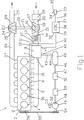
図1は、ターボ過給式のピストン内燃機関に新空気を供給するための装置を概略的に示す図であり、
図2は、図1に示した装置の新ガス管路区分を示す断面図であり、
図3は、新ガス管路区分を流入端部から見た不等角投影図であり、
図4は、新ガス管路区分を流出端部から見た不等角投影図であり、
図5は、新ガス管路区分を上方から見た不等角投影図である。
FIG. 1 is a diagram schematically showing an apparatus for supplying new air to a turbocharged piston internal combustion engine.
FIG. 2 is a cross-sectional view showing a new gas pipeline section of the apparatus shown in FIG.
FIG. 3 is an isometric view of the new gas line section as seen from the inflow end,
FIG. 4 is an isometric view of the new gas line section as seen from the outflow end,
FIG. 5 is an axonometric view of the new gas line section as viewed from above.
図1に示したように、ターボ過給式のディーゼルエンジン2は直列型の6つのシリンダ3を有している。これらのシリンダ3の6つの吸気管路4は1つの集合管路(マニホルド)5に接続されている。集合管路5は接続フランジ7を有しており、この接続フランジ7には、新ガス管路区分8の、流出のための第2の端接続部9が接続されている。流入のための第1の端接続部10は管路11によって過給空気冷却のためのインタクーラ13の流出開口12に連結されている。インタクーラ13の流入開口14は管路15によってターボコンプレッサ17の流出開口16に連結されている。ターボコンプレッサ17の流入開口18には、管路20によってエアフィルタ19が接続されている。ターボコンプレッサ17は排ガスターボチャージャ22の一部を形成している。排ガスターボチャージャ22はさらに排ガスタービン23を有しており、排ガスタービン23の流入開口24は排気集合管(排気マニホルド)26の流出開口25に接続されている。ターボコンプレッサ17と排ガスタービン23とはシャフト21に固定されている。シリンダ3はそれぞれ排気管路27によって1つの排気集合管26に接続されている。排ガスタービン23の流出開口28は排ガス管29と連結されている。
As shown in FIG. 1, the turbocharged diesel engine 2 has six cylinders 3 in series. The six intake lines 4 of these cylinders 3 are connected to one collecting line (manifold) 5. The collecting pipe 5 has a connection flange 7, and a second end connection portion 9 for the outflow of the new
シリンダ3への燃料供給は噴射ノズル30により行われる。これらの噴射ノズル30の制御は線路31によって電子制御ユニット38の第1の出力部32によって実施される。電子制御ユニット38の入力部37には、電子制御ユニット33の出力部34が線路36によって接続されている。制御ユニット33は操作機構を備えており、この操作機構は本実施例ではアクセルペダル35として形成されている。電子制御ユニット38の電気的な接続部39は集合線路40によって新ガス管路区分8の電気的な接続部41に接続されている。
The fuel supply to the cylinder 3 is performed by the
新ガス管路区分8は圧縮空気接続部42を有している。この圧縮空気接続部42は管路43によって圧縮空気タンク45の流出接続部44に接続されている。圧縮空気タンク45への供給のための供給接続部46は管路47によって圧縮空気コンプレッサ49の圧縮空気接続部48に接続されている。この管路47には、プレッシャレギュレータ50と空気乾燥器51とが組み込まれている。圧縮空気コンプレッサ49は吸込管片52を有しており、この吸込管片52はエアフィルタ53を備えている。圧縮空気コンプレッサ49のシャフト54はベルト駆動装置55によって、ターボ過給式のディーゼルエンジンのメインシャフト56に結合されている。
The new
図2には、新ガス管路区分8が詳細に図示されている。この新ガス管路区分8は管状に形成されていて、第1の端接続部10と第2の端接続部9とを有している。第1の端接続部10と第2の端接続部9との間には内室57が設けられおり、この内室57は円形横断面を有している。内室57は壁58によって取り囲まれており、この壁58にはスロットルバルブのバタフライもしくはフラップ60のシャフト59が支承されかつ貫通案内されている。フラップ60は内室57を2つの部分、つまり第1の端接続部10とフラップ60との間に形成される流入室61と、第2の端接続部9とフラップ60との間に形成される流出室62とに分割している。フラップ60は閉じられた位置と、完全に開かれた位置と、両位置の間の任意の位置とを有しており、これらの位置はシャフト59の回転によって調節される。調節装置66は本実施例では電気的なモータとして形成されていて、電気的な調節装置入力部74と出力部65とを備えている。調節装置入力部74と出力部65とは、相応して電子制御ユニット38の集合線路40の接続部に接続されている。調節装置入力部74により、調節装置66には電流が供給される。出力部65からは、フラップ60の位置に関する信号が取り出される。壁58では、第2の端接続部9とフラップ60との間に圧縮空気流入開口67が形成されている。この圧縮空気流入開口67には圧縮空気接続部42が接続されており、この圧縮空気接続部42は量制御装置68を装備している。この量制御装置68は、完全に遮断された位置をも有している。弁70を有する量制御装置68の電気的な制御入力部69は電子制御ユニット38の集合線路40に接続されている。
FIG. 2 shows the new
同様に、電子制御ユニット38の集合線路40には、壁58に取り付けられている圧力センサもしくは圧力フィーラ72の出力部71と、新ガス管路区分8の流出室62内へ突入して延びる、圧力フィーラ72の圧力測定器73と、壁58に取り付けられている圧力フィーラ72の類似の出力部71と、流入室61内に突入して延びる、圧力フィーラ72の圧力測定器73とが接続されている。
Similarly, the
このように配置された装置1は次のように機能する:ターボ過給式のディーゼルエンジンのシリンダには、回転数が一定になると、吸気管路4と、集合管路5と、新ガス供給区分8と、管路11と、インタクーラ13と、管路15と、ターボコンプレッサ17と、エアフィルタ19とを通じて新ガスが供給される。排ガスは排気管路27と、排気集合管26と、排ガスタービン23と、排ガス管29とを通じてシリンダ3から流出する。
The device 1 arranged in this way functions as follows: the cylinder of a turbocharged diesel engine, when the speed is constant, the intake line 4, the collecting line 5 and the new gas supply New gas is supplied through the
トルクもしくはエンジン回転数を急速に増大させたるために運転者がアクセルペダル35を迅速に踏み込むと、ターボ過給式のディーゼルエンジン2は、より多くの燃料と、寄り多くの新ガスとを必要とする。付加的な燃料はシリンダ3内へ案内されるが、しかし排ガスターボチャージャ22により供給される新ガス量の増大は不十分なままとなる。内室57内で常時圧力測定器73により測定されかつ圧力フィーラ72により電子制御ユニット38へ伝送される新ガスの圧力も低い。このような運転状態では、フラップ60が完全に開かれている。電子制御ユニット38は、圧力が内室57内で十分に迅速には増大しないことを検知し、そして制御プログラムにより、付加的な空気吹込みを実施した方がよいことを確認する。
When the driver quickly depresses the
制御プロフラムは、空気吹込みをいつ開始すればよいのかを知るための条件に関する、予め規定されたデータを有している。開始時には、フラップ60が「閉鎖」の方向に旋回させられ、圧縮空気タンク45から流出室62への圧縮空気吹込み路が解放される。空気吹込みの時間は同じく制御プロフラムにより規定される。この場合、制御プロフラムは、圧力測定器73により測定された圧力差および絶対圧を考慮する。
The control program has predefined data regarding the conditions for knowing when to start air blowing. At the start, the
職業的な長距離トラック運転手またはバス運転手であれば誰でも、平均的な加速値を求めるそれぞれ独自の走行形態を有している。すなわち、これらの運転手は変速機の特定の変速点もしくはシフト点を利用しており、この変速機の特性値は検出され、記憶され、かつ処理され得る。このことは、電子制御ユニット38の演算装置で実施されて、ソフトウェアにより空気吹込みおよびフラップ操作の時間に電子制御ユニット38において使用される。このソフトウェアにより、圧縮空気タンク45の空気消費量がブレーキ安全性に不都合な影響を与えてしまうほど高くなることが阻止されると望ましい。なぜならば、圧縮空気タンク45は全圧縮空気システムの一部であり、そのうち最も重要な部分は、安全性の点でブレーキシステムであるからである。それにもかかわらず、加速補助において急激な変化が生じることは、やはり許容され得ない。
Every professional long-distance truck driver or bus driver has its own mode of travel that seeks an average acceleration value. That is, these drivers utilize a specific shift point or shift point of the transmission, and the characteristic value of this transmission can be detected, stored and processed. This is implemented in the arithmetic unit of the
このような課題は原理的には、空気吹込みおよびフラップ操作の時間を運転手意志の頻度に応じて制御ソフトウェアによって適応制御することにより解決される。これにより、空気消費量は特定の範囲内に保持され、しかも空気吹込みの時間における急激な変化なしに保持される。こうして、運転者が加速補助の際に、予期しない変化、つまり加速減少を認識することが回避される。 In principle, such a problem is solved by adaptively controlling the time of air blowing and flap operation by the control software according to the frequency of the driver's will. As a result, the air consumption is maintained within a specific range, and is maintained without a rapid change in the time of air blowing. Thus, the driver is prevented from recognizing an unexpected change, that is, a decrease in acceleration when assisting acceleration.
1 装置
2 ターボ過給式のディーゼルエンジン
3 シリンダ
4 吸気管路
5 集合管路
6 シリンダブロック
7 接続フランジ
8 新ガス管路区分
9 第2の端接続部「流出」
10 第1の端接続部「流入」
11 管路
12 流出開口
13 インタクーラ
14 流入開口
15 管路
16 流出開口
17 ターボコンプレッサ
18 流入開口
19 エアフィルタ
20 管路
21 シャフト
22 排ガスターボチャージャ
23 排ガスタービン
24 流入開口
25 流出開口
26 排気集合管
27 排気管路
28 流出開口
29 排ガス管
30 噴射ノズル
31 線路
32 出力部
33 任意の制御ユニット
34 出力部
35 アクセルペダル
36 線路
37 入力部
38 電子制御ユニット
39 接続部
40 集合線路
41 接続部
42 圧縮空気接続部
43 管路
44 流出接続部
45 圧縮空気タンク
46 供給接続部
47 管路
48 圧縮空気接続部
49 圧縮空気コンプレッサ
50 プレッシャレギュレータ
51 空気乾燥器
52 吸込管片
53 エアフィルタ
54 シャフト
55 ベルト駆動装置
56 メインシャフト
57 内室
58 壁
59 シャフト
60 フラップ
61 流入室
62 流出室
63 位置検出センサ
64 外面
65 出力部
66 調節装置
67 圧縮空気流入開口
68 量制御装置
69 電気的な制御入力部
70 弁
71 出力部
72 圧力フィーラ
73 圧力測定器
74 調節装置入力部
DESCRIPTION OF SYMBOLS 1 Apparatus 2 Turbocharged diesel engine 3 Cylinder 4 Intake line 5
10 First end connection "inflow"
DESCRIPTION OF SYMBOLS 11
Claims (5)
−トルク要求信号を求めて、データを電子制御ユニット(38)に供給し、
−エンジン特性値を求めて、該特性値を電子制御ユニット(38)に供給し、
−シリンダ吸気弁とフラップ(60)との間の吸気管路の内室内の空気圧を求めて、圧力値を電子制御ユニット(38)に供給し、かつフラップ(60)とターボコンプレッサとの間の吸気管路の内室内の空気圧を求めて、圧力値を電子制御ユニット(38)に供給し、
−新ガス管路区分(8)内への一時的な吹込みの弁(70)の開閉を行うと同時に、吹込みの開始時における閉鎖方向へのフラップ(60)の操作と、吹込み終了時における開放方向へのフラップ(60)の操作とを行うための操作−出力信号を形成するために、前で挙げたデータおよび測定値を電子制御ユニット(38)で処理する、
を実施することを特徴とする、車両−ピストン内燃機関の加速・エミッション特性を改善する方法。Vehicle having a turbocharger - A method of improving the acceleration and emission characteristics of the piston internal combustion agencies, be equipped with compressed air accumulator device according to any one of claims 1 to 3, the compressed air in the accumulator In a method of the type of storing compressed air for controlled temporary injection into the new gas line section (8) of the engine cylinder, the following method steps:
Obtaining a torque request signal and supplying the data to the electronic control unit (38);
Determining the engine characteristic value and supplying it to the electronic control unit (38);
-Determining the air pressure in the interior of the intake line between the cylinder intake valve and the flap (60), supplying the pressure value to the electronic control unit (38), and between the flap (60) and the turbo compressor; The air pressure in the inner chamber of the intake pipe is obtained, and the pressure value is supplied to the electronic control unit (38).
-Opening and closing of the valve (70) for temporary blowing into the new gas line section (8), at the same time the operation of the flap (60) in the closing direction at the start of blowing and the end of blowing Processing the previously mentioned data and measurement values in the electronic control unit (38) to form an operation-output signal for performing the operation of the flap (60) in the opening direction at the time,
A method for improving the acceleration and emission characteristics of a vehicle-piston internal combustion engine.
−電子制御ユニット(38)内のソフトウェアにより、運転者の加速意志の平均的な頻度を求め、
−空気消費量が規定の範囲内に保持され、ただし空気吹込みの時間における空気消費量の急激な変化なしに保持されることを達成するために、求められた、運転者の加速意志の平均的な頻度に適応させて空気吹込みおよびフラップ操作を制御する、
を実施する、請求項4記載の方法。The following method steps:
-The software in the electronic control unit (38) determines the average frequency of the driver 's acceleration will,
-The average of the driver 's acceleration intentions required to achieve that the air consumption is kept within a specified range, but without abrupt changes in air consumption during the time of air blowing. To control air blowing and flap operation, adapting to the frequency of
The method of claim 4, wherein:
Applications Claiming Priority (5)
| Application Number | Priority Date | Filing Date | Title |
|---|---|---|---|
| DE102005008405 | 2005-02-24 | ||
| DE102005008405.2 | 2005-02-24 | ||
| DE102005051687 | 2005-10-28 | ||
| DE102005051687.4 | 2005-10-28 | ||
| PCT/EP2006/001737 WO2006089779A1 (en) | 2005-02-24 | 2006-02-24 | Device for supplying fresh air to a turbocharged piston internal combustion engine and method for operating the same |
Publications (2)
| Publication Number | Publication Date |
|---|---|
| JP2008531907A JP2008531907A (en) | 2008-08-14 |
| JP4843621B2 true JP4843621B2 (en) | 2011-12-21 |
Family
ID=36121667
Family Applications (2)
| Application Number | Title | Priority Date | Filing Date |
|---|---|---|---|
| JP2007556564A Expired - Fee Related JP4886705B2 (en) | 2005-02-24 | 2006-02-24 | Fresh gas supply system for turbocharged piston internal combustion engine |
| JP2007556563A Expired - Fee Related JP4843621B2 (en) | 2005-02-24 | 2006-02-24 | Apparatus for supplying fresh air to a turbocharged piston internal combustion engine and method of operating the apparatus |
Family Applications Before (1)
| Application Number | Title | Priority Date | Filing Date |
|---|---|---|---|
| JP2007556564A Expired - Fee Related JP4886705B2 (en) | 2005-02-24 | 2006-02-24 | Fresh gas supply system for turbocharged piston internal combustion engine |
Country Status (11)
| Country | Link |
|---|---|
| US (2) | US7926271B2 (en) |
| EP (2) | EP1856388B1 (en) |
| JP (2) | JP4886705B2 (en) |
| KR (2) | KR101258307B1 (en) |
| AT (2) | ATE438027T1 (en) |
| BR (2) | BRPI0609244B1 (en) |
| CA (2) | CA2599078C (en) |
| DE (2) | DE502006001029D1 (en) |
| MX (2) | MX2007010194A (en) |
| RU (2) | RU2394995C2 (en) |
| WO (2) | WO2006089780A1 (en) |
Families Citing this family (65)
| Publication number | Priority date | Publication date | Assignee | Title |
|---|---|---|---|---|
| DE102007027968A1 (en) | 2007-06-19 | 2009-01-02 | Knorr-Bremse Systeme für Nutzfahrzeuge GmbH | Method and device for increasing the engine braking power of a reciprocating internal combustion engine of a vehicle, in particular a diesel engine |
| DE102007035163B4 (en) * | 2007-07-25 | 2012-10-18 | Knorr-Bremse Systeme für Nutzfahrzeuge GmbH | Compressed air system |
| ATE488681T1 (en) * | 2007-07-27 | 2010-12-15 | Waertsilae Nsd Schweiz Ag | TWO-STROKE DIESEL INTERNATIONAL ENGINE |
| CN101772627B (en) * | 2007-08-17 | 2013-06-19 | 博格华纳公司 | Boost assist system |
| DE102007045623B4 (en) * | 2007-09-24 | 2009-07-23 | Knorr-Bremse Systeme für Nutzfahrzeuge GmbH | Method and apparatus for improving exhaust gas recirculation of an internal combustion engine |
| DE102007045622B4 (en) * | 2007-09-24 | 2012-10-04 | Knorr-Bremse Systeme für Nutzfahrzeuge GmbH | Method for regulating an intake pressure of an internal combustion engine |
| DE102008026023A1 (en) * | 2008-05-30 | 2009-12-03 | Voith Patent Gmbh | Drive train and method for supplying a compressed air system |
| DE102008008723B4 (en) * | 2008-02-12 | 2013-07-11 | Knorr-Bremse Systeme für Nutzfahrzeuge GmbH | Method and device for generating compressed air and for blowing the same in an internal combustion engine |
| DE102008000324A1 (en) * | 2008-02-18 | 2009-08-20 | Zf Friedrichshafen Ag | Method for controlling the compressed air supply of an internal combustion engine and a transmission |
| DE102008000325A1 (en) | 2008-02-18 | 2009-08-20 | Zf Friedrichshafen Ag | Method and device for controlling a compressed air supply of an internal combustion engine and other devices |
| DE102008000326A1 (en) | 2008-02-18 | 2009-08-20 | Zf Friedrichshafen Ag | Method for controlling a compressed air supply of an internal combustion engine during a starting process |
| CA2715275C (en) | 2008-02-28 | 2016-07-05 | Knorr-Bremse Systeme Fur Nutzfahrzeuge Gmbh | Method and device for controlling an output torque of an automated transmission coupled to an internal combustion engine |
| US7975666B2 (en) * | 2008-02-28 | 2011-07-12 | General Electric Company | Quick engine startup system and method |
| JP2009281195A (en) * | 2008-05-20 | 2009-12-03 | Toyota Motor Corp | Control device for internal combustion engine |
| DE102008047802A1 (en) * | 2008-09-17 | 2010-04-01 | Knorr-Bremse Systeme für Nutzfahrzeuge GmbH | Fresh gas supply device for an internal combustion engine with turbocharger and method for its control |
| DE102008048366A1 (en) | 2008-09-22 | 2010-04-08 | Knorr-Bremse Systeme für Nutzfahrzeuge GmbH | Arrangement for supplying fresh gas to a turbocharged internal combustion engine and method for controlling the arrangement |
| DE202008017549U1 (en) | 2008-10-21 | 2009-12-24 | Knorr-Bremse Systeme für Nutzfahrzeuge GmbH | Fresh gas supply device for an internal combustion engine |
| DE102009007690B4 (en) | 2009-02-05 | 2019-06-06 | Knorr-Bremse Systeme für Nutzfahrzeuge GmbH | Method and device for regulating a charge air pressure of an internal combustion engine of a vehicle |
| DE102009022229A1 (en) * | 2009-05-20 | 2010-11-25 | Knorr-Bremse Systeme für Nutzfahrzeuge GmbH | Housing a fresh gas supply device for an internal combustion engine and fresh gas supply device |
| DE102009034684A1 (en) | 2009-07-24 | 2011-05-12 | Voith Patent Gmbh | Injector, in particular for the compressed air charging of an internal combustion engine |
| CH701760A8 (en) * | 2009-09-10 | 2012-02-29 | Eth Zuerich | Turbocharged reciprocating piston engine with connected pressure tank for turbocharger bridging and method for operating the same. |
| EP2462328B1 (en) * | 2009-08-03 | 2013-07-03 | ETH Zurich | Turbocharged reciprocating piston engine having a connected pressure tank for bridging turbo lag, and method for operating said engine |
| US8281587B2 (en) * | 2009-08-13 | 2012-10-09 | International Engine Intellectual Property Company, Llc | Supercharged boost-assist engine brake |
| DE102009037639A1 (en) | 2009-08-14 | 2011-02-17 | Knorr-Bremse Systeme für Nutzfahrzeuge GmbH | Device arrangement and method for controlling a compressor pressure of a supercharged internal combustion engine with Frischluftzuführeinrichtung |
| DE102010021753B4 (en) * | 2009-12-17 | 2016-02-04 | Deutz Ag | Regeneration of particle filters |
| DE102009060181A1 (en) | 2009-12-23 | 2011-06-30 | Knorr-Bremse Systeme für Nutzfahrzeuge GmbH, 80809 | Exhaust gas turbocharger for an internal combustion engine with a fresh gas supply device and a corresponding arrangement |
| DE102010004657B4 (en) * | 2010-01-14 | 2012-03-22 | Knorr-Bremse Systeme für Nutzfahrzeuge GmbH | Fresh gas supply device for an internal combustion engine and method for operating such a fresh gas supply device |
| US8069665B2 (en) | 2010-04-15 | 2011-12-06 | Ford Global Technologies, Llc | Stored compressed air management for improved engine performance |
| US8434305B2 (en) | 2010-05-06 | 2013-05-07 | Honeywell International Inc. | Compressed-air-assisted turbocharger system for internal combustion engine |
| US8381521B2 (en) | 2010-05-19 | 2013-02-26 | Bendix Commercial Vehicle Systems Llc | Vehicle pneumatic booster system operating method and apparatus |
| US8428844B2 (en) | 2010-05-19 | 2013-04-23 | Bendix Commercial Vehicle Systems Llc | Vehicle pneumatic booster system operating method and apparatus |
| US8412424B2 (en) | 2010-05-19 | 2013-04-02 | Bendix Commercial Vehicle Systems Llc | Vehicle pneumatic booster system operating method and apparatus |
| US8805606B2 (en) | 2010-05-19 | 2014-08-12 | Bendix Commercial Vehicle Systems Llc | Vehicle pneumatic booster system operating method and apparatus |
| DE102010024060B4 (en) | 2010-06-17 | 2012-04-05 | Knorr-Bremse Systeme für Nutzfahrzeuge GmbH | Fresh gas supply device for an internal combustion engine |
| DE102010034727A1 (en) | 2010-08-18 | 2012-02-23 | Knorr-Bremse Systeme für Nutzfahrzeuge GmbH | Method for regulating a stable operation of an exhaust gas turbocharger of an internal combustion engine and a corresponding device |
| JP5605161B2 (en) * | 2010-10-21 | 2014-10-15 | いすゞ自動車株式会社 | Supercharging assist device for internal combustion engine |
| DE102010054049B4 (en) | 2010-12-10 | 2016-07-07 | Knorr-Bremse Systeme für Nutzfahrzeuge GmbH | Method for starting an internal combustion engine and internal combustion engine with starting aid device |
| US8666634B2 (en) | 2011-02-25 | 2014-03-04 | Bendix Commercial Vehicle Systems Llc | Method of operating a vehicle equipped with a pneumatic booster system |
| US8484971B2 (en) * | 2011-02-25 | 2013-07-16 | Bendix Commercial Vehicle Systems Llc | Method of operating a vehicle equipped with a pneumatic booster system |
| US8468824B2 (en) | 2011-02-25 | 2013-06-25 | Bendix Commercial Vehicle Systems Llc | Method of operating a vehicle equipped with a pneumatic booster system |
| US8505297B2 (en) | 2011-02-25 | 2013-08-13 | Bendix Commercial Vehicle Systems Llc | Method of operating a vehicle equipped with a pneumatic booster system |
| US20120227399A1 (en) * | 2011-03-11 | 2012-09-13 | International Engine Intellectual Property Company, Llc | In-flow air injection housing |
| DE102011005502B4 (en) * | 2011-03-14 | 2014-02-13 | Ford Global Technologies, Llc | Method and device for controlling a starting process of a motor vehicle |
| US8567191B2 (en) * | 2011-03-25 | 2013-10-29 | General Electric Company | Methods and systems for controlling transient engine response |
| JP5994232B2 (en) * | 2011-11-07 | 2016-09-21 | いすゞ自動車株式会社 | Start acceleration assist device |
| JP2013096397A (en) * | 2011-11-07 | 2013-05-20 | Isuzu Motors Ltd | Start acceleration assistance device |
| EP2799320B1 (en) * | 2011-12-28 | 2020-11-18 | Kawasaki Jukogyo Kabushiki Kaisha | Electric straddled vehicle |
| EP2667006A1 (en) * | 2012-05-25 | 2013-11-27 | Turner Powertrain Systems Limited | Engine boosting system |
| JP6031841B2 (en) * | 2012-06-14 | 2016-11-24 | いすゞ自動車株式会社 | Method for cleaning EGR valve of internal combustion engine and internal combustion engine |
| SE540017C2 (en) * | 2012-07-05 | 2018-02-27 | Scania Cv Ab | Procedure and system for driving a vehicle, where the charge pressure is controlled |
| DE102012221403A1 (en) | 2012-11-22 | 2014-05-22 | Bayerische Motoren Werke Aktiengesellschaft | Method for operating a spark-ignited internal combustion engine with an exhaust gas turbocharger |
| US20140158099A1 (en) * | 2012-12-10 | 2014-06-12 | Bendix Commercial Vehicle Systems Llc | System and Method for Improved Emissions Control |
| DE102013100096B4 (en) | 2013-01-07 | 2015-01-29 | Knorr-Bremse Systeme für Nutzfahrzeuge GmbH | Device and method for exhaust gas recirculation of an internal combustion engine and a corresponding internal combustion engine |
| DE102013101988A1 (en) * | 2013-02-28 | 2014-08-28 | Maschinenfabrik Rieter Ag | Spinning station for producing a yarn |
| US9599013B2 (en) * | 2013-04-15 | 2017-03-21 | Ford Global Technologies, Llc | Direct manifold boost assist device with throttle body manifold volume isolation |
| ITMI20131608A1 (en) * | 2013-09-30 | 2015-03-31 | Fpt Ind Spa | PREVENTION SYSTEM OF A MECHANICAL DAMAGE OF AN INTERNAL COMBUSTION ENGINE DUE TO AN INEFFICIENT LUBRICATION OF THE SAME |
| CN104847484A (en) * | 2014-04-10 | 2015-08-19 | 北汽福田汽车股份有限公司 | Device and method for utilizing negative pressure energy of engine |
| RU167883U1 (en) * | 2015-07-22 | 2017-01-11 | Виктор Гурийевич Сильков | A device for preparing and supplying air to an internal combustion engine. |
| WO2017014668A1 (en) * | 2015-07-22 | 2017-01-26 | Виктор Гурийевич СИЛЬКОВ | Device and method for supplying air to an internal combustion engine |
| DE102015221624A1 (en) * | 2015-11-04 | 2017-05-04 | Bayerische Motoren Werke Aktiengesellschaft | Method and device for generating a noise characterizing an operation of an internal combustion engine |
| DE102016119426B4 (en) * | 2016-10-12 | 2020-03-12 | Pierburg Gmbh | Flap device for an internal combustion engine |
| US10539080B2 (en) | 2017-04-21 | 2020-01-21 | Peter Chargo | Internal combustion engine injection system |
| CN108547701A (en) * | 2018-04-03 | 2018-09-18 | 苏伟 | Full working scope shunting timesharing super charge internal-combustion engine variable compression ratio technique |
| US10954893B2 (en) | 2018-08-30 | 2021-03-23 | Kohler, Co. | Accumulator device |
| IT202000000991A1 (en) | 2020-01-20 | 2021-07-20 | Fpt Ind Spa | VEHICLE ENGINE SYSTEM EQUIPPED WITH A TURBOCHARGER, AND METHOD OF CONTROL TO CONTROL THIS ENGINE SYSTEM |
Citations (1)
| Publication number | Priority date | Publication date | Assignee | Title |
|---|---|---|---|---|
| JPH08260991A (en) * | 1995-03-28 | 1996-10-08 | Nissan Diesel Motor Co Ltd | Intake device for engine having turbo charger |
Family Cites Families (43)
| Publication number | Priority date | Publication date | Assignee | Title |
|---|---|---|---|---|
| US2983267A (en) * | 1959-04-24 | 1961-05-09 | Gen Motors Corp | Accumulator supercharging |
| US3020901A (en) * | 1961-01-24 | 1962-02-13 | Thompson Ramo Wooldridge Inc | Supercharger for internal combustion engines |
| US3427802A (en) * | 1966-08-31 | 1969-02-18 | Dresser Ind | Gas starting arrangement for two-cycle turbocharged engine |
| BE758005A (en) | 1969-12-03 | 1971-04-01 | Kloeckner Humboldt Deutz Ag | IMMEDIATELY AVAILABLE CURRENT GENERATOR RESERVE KIT |
| US3673796A (en) * | 1970-03-03 | 1972-07-04 | Caterpillar Tractor Co | Anticipating air injection system for turbocharged engines |
| US3675796A (en) * | 1971-03-08 | 1972-07-11 | James D Atkinson | Fill pipe for silo |
| GB2095328B (en) * | 1981-02-06 | 1984-08-30 | Honda Motor Co Ltd | Controlling supercharged ic engine intake systems |
| JPS57191423A (en) * | 1981-05-19 | 1982-11-25 | Honda Motor Co Ltd | Supercharged pressure display device for internal combustion engine provided with supercharger |
| JPS58152521U (en) * | 1982-04-07 | 1983-10-12 | 株式会社小松製作所 | turbocharged engine |
| JPS60204918A (en) * | 1984-03-30 | 1985-10-16 | Nissan Motor Co Ltd | Suction device for internal-combustion engine |
| DE3737743A1 (en) * | 1987-11-06 | 1989-05-18 | Marinetechnik Gmbh | Method for operating a high-speed, supercharged diesel engine, and diesel engine for carrying out the method |
| EP0369189A1 (en) * | 1988-11-02 | 1990-05-23 | Volkswagen Aktiengesellschaft | Driving system for vehicles, especially passenger cars |
| DE3841983A1 (en) | 1988-12-14 | 1990-06-21 | Kloeckner Humboldt Deutz Ag | EXHAUST PIPE SYSTEM FOR A CHARGED INTERNAL COMBUSTION ENGINE |
| JPH02215930A (en) | 1989-02-16 | 1990-08-28 | Riken Corp | Supercharger for internal combustion engine |
| DE3906312C1 (en) * | 1989-02-28 | 1989-12-21 | Man Nutzfahrzeuge Ag, 8000 Muenchen, De | |
| JPH06299879A (en) * | 1993-04-15 | 1994-10-25 | Mitsubishi Motors Corp | Smoke discharge preventing device during free acceleration |
| JP2794522B2 (en) * | 1993-09-24 | 1998-09-10 | 株式会社クボタ | Two-stroke engine air supply system |
| DE4443502A1 (en) | 1994-12-07 | 1996-06-13 | Bosch Gmbh Robert | Device for an internal combustion engine |
| DE19507354B4 (en) | 1995-03-03 | 2009-12-10 | Continental Automotive Gmbh | Suction module for a gasoline engine |
| US5819538A (en) * | 1996-11-15 | 1998-10-13 | Lawson, Jr.; Thomas Towles | Turbocharged engine system with recirculation and supplemental air supply |
| JP3329220B2 (en) * | 1997-01-31 | 2002-09-30 | スズキ株式会社 | Intake structure of supercharged engine |
| JPH1122572A (en) * | 1997-06-30 | 1999-01-26 | Suzuki Motor Corp | Resonator structure for internal combustion engine |
| DE19728349A1 (en) | 1997-07-03 | 1999-01-07 | Telefunken Microelectron | Sensor arrangement and engine control device for an internal combustion engine |
| DE19840616C1 (en) | 1998-09-05 | 1999-12-02 | Daimler Chrysler Ag | V=engine with mechanically driven turbocharger |
| FR2783283B1 (en) | 1998-09-14 | 2000-11-24 | Mark Iv Systemes Moteurs Sa | INTEGRATED INTAKE MANIFOLD / BUTTERFLY HOUSING |
| DE19913157A1 (en) * | 1999-03-24 | 2000-10-05 | Theodor Thies | Charge pressure raising device for internal combustion engine, involving accelerating charge flow through one or more amplifiers with annular jets |
| DE19944946A1 (en) * | 1999-09-20 | 2001-03-29 | Udo Reilaender | Unit to charge internal combustion engine outside optimum working area of charger; has pressure container, valve and pressure generator to supply gas in other areas continuously to pressure container |
| JP2001234761A (en) * | 2000-02-21 | 2001-08-31 | Hitachi Ltd | Module for internal combustion engine and intake device |
| US6618631B1 (en) * | 2000-04-25 | 2003-09-09 | Georgia Tech Research Corporation | Adaptive control system having hedge unit and related apparatus and methods |
| JP2002285866A (en) * | 2001-03-27 | 2002-10-03 | Denso Corp | Throttle device and its manufacturing method |
| DE10117542A1 (en) * | 2001-04-07 | 2002-10-10 | Siemens Ag | Throttle body and electronics module |
| DE10123492B4 (en) * | 2001-05-15 | 2005-06-30 | Dr.Ing.H.C. F. Porsche Ag | Intake device for an internal combustion engine |
| JP4464581B2 (en) * | 2001-05-24 | 2010-05-19 | 本田技研工業株式会社 | Engine intake air amount control device |
| FR2833650B1 (en) * | 2001-12-14 | 2004-12-24 | Peugeot Citroen Automobiles Sa | MOTORIZATION SYSTEM FOR MOTOR VEHICLE |
| JP4000994B2 (en) * | 2002-11-25 | 2007-10-31 | 株式会社日立製作所 | Throttle body and intake device for internal combustion engine |
| DE10303391B4 (en) * | 2003-01-29 | 2016-12-15 | Robert Bosch Gmbh | Method and device for operating a drive unit with an internal combustion engine |
| US6907868B2 (en) | 2003-03-14 | 2005-06-21 | Siemens Vdo Automotive, Inc. | Modular exhaust gas recirculation assembly |
| US7201159B2 (en) * | 2003-03-14 | 2007-04-10 | Siemens Canada Limited | Electric actuator assembly and method for controlling an exhaust gas recirculation assembly |
| JP2005147108A (en) * | 2003-11-20 | 2005-06-09 | Hitachi Ltd | Electronic control throttle device |
| JP2005188408A (en) * | 2003-12-26 | 2005-07-14 | Mikuni Corp | Throttle device |
| DE10361913A1 (en) * | 2003-12-31 | 2005-09-08 | Birgit Bergmann | "Turbo lag" (charging support with storage) |
| JP2006002633A (en) * | 2004-06-16 | 2006-01-05 | Yamaha Marine Co Ltd | Water jet propulsion boat |
| JP2008002326A (en) * | 2006-06-21 | 2008-01-10 | Works Bell:Kk | Joint hose disconnection preventive tool |
-
2004
- 2004-09-10 MX MX2007010194A patent/MX2007010194A/en active IP Right Grant
-
2006
- 2006-02-24 MX MX2007010195A patent/MX2007010195A/en active IP Right Grant
- 2006-02-24 WO PCT/EP2006/001738 patent/WO2006089780A1/en active IP Right Grant
- 2006-02-24 CA CA2599078A patent/CA2599078C/en not_active Expired - Fee Related
- 2006-02-24 AT AT06723109T patent/ATE438027T1/en active
- 2006-02-24 EP EP06723109A patent/EP1856388B1/en not_active Not-in-force
- 2006-02-24 BR BRPI0609244-6A patent/BRPI0609244B1/en active Search and Examination
- 2006-02-24 JP JP2007556564A patent/JP4886705B2/en not_active Expired - Fee Related
- 2006-02-24 EP EP06723110A patent/EP1856389B1/en not_active Not-in-force
- 2006-02-24 KR KR1020077021537A patent/KR101258307B1/en not_active IP Right Cessation
- 2006-02-24 AT AT06723110T patent/ATE399932T1/en not_active IP Right Cessation
- 2006-02-24 CA CA2599086A patent/CA2599086C/en not_active Expired - Fee Related
- 2006-02-24 DE DE502006001029T patent/DE502006001029D1/en active Active
- 2006-02-24 KR KR1020077021535A patent/KR101179799B1/en active IP Right Grant
- 2006-02-24 DE DE502006004372T patent/DE502006004372D1/en active Active
- 2006-02-24 BR BRPI0609245-4A patent/BRPI0609245A2/en not_active IP Right Cessation
- 2006-02-24 RU RU2007135027/06A patent/RU2394995C2/en not_active IP Right Cessation
- 2006-02-24 RU RU2007135021/06A patent/RU2392457C2/en not_active IP Right Cessation
- 2006-02-24 WO PCT/EP2006/001737 patent/WO2006089779A1/en active Application Filing
- 2006-02-24 JP JP2007556563A patent/JP4843621B2/en not_active Expired - Fee Related
-
2007
- 2007-08-24 US US11/844,474 patent/US7926271B2/en active Active
- 2007-08-24 US US11/844,468 patent/US7665302B2/en not_active Expired - Fee Related
Patent Citations (1)
| Publication number | Priority date | Publication date | Assignee | Title |
|---|---|---|---|---|
| JPH08260991A (en) * | 1995-03-28 | 1996-10-08 | Nissan Diesel Motor Co Ltd | Intake device for engine having turbo charger |
Also Published As
Similar Documents
| Publication | Publication Date | Title |
|---|---|---|
| JP4843621B2 (en) | Apparatus for supplying fresh air to a turbocharged piston internal combustion engine and method of operating the apparatus | |
| JP4595701B2 (en) | Control device for internal combustion engine having supercharger with electric motor | |
| US8006495B2 (en) | Supercharging system for internal combustion engine | |
| US9267426B2 (en) | Internal combustion engine wastegate valve controller | |
| JP2010501763A (en) | Apparatus and method for fresh air supply in a turbocharged piston internal combustion engine | |
| JP4434174B2 (en) | Control device for an internal combustion engine with a supercharger | |
| EP3406880B1 (en) | Waste gate valve control method and control device | |
| CN104564318A (en) | Control device and control method for internal combustion engine | |
| JPH0823299B2 (en) | Turbocharging pressure control device for turbocharged internal combustion engine | |
| CN104675513A (en) | Control method for turbocharger | |
| JP6848840B2 (en) | Wastegate valve controller | |
| US11707989B2 (en) | Method for protecting an electric machine of a motor vehicle | |
| JP2007303294A (en) | Control device for internal combustion engine with supercharger | |
| US20160108858A1 (en) | Control apparatus and control method for internal combustion engine | |
| JP4518045B2 (en) | Control device for an internal combustion engine with a supercharger | |
| JP6128425B2 (en) | Supercharger control device for internal combustion engine | |
| JPH07119475A (en) | Control unit of internal combustion engine | |
| US20230410570A1 (en) | Vehicle | |
| JPH09329040A (en) | Output control device for internal combustion engine | |
| JP2018145845A (en) | Control device for internal combustion engine | |
| KR100773697B1 (en) | System and method for controlling charging pressure of turbo-charger engine | |
| JP3714390B2 (en) | Internal combustion engine with a supercharger | |
| JP2019105261A (en) | Waste gate valve control device | |
| JPH0754675A (en) | Intake throttle valve control device of electronic control type diesel engine | |
| JPH04246236A (en) | Supercharge pressure controller for engine equipped with supercharger |
Legal Events
| Date | Code | Title | Description |
|---|---|---|---|
| A621 | Written request for application examination |
Free format text: JAPANESE INTERMEDIATE CODE: A621 Effective date: 20080916 |
|
| A131 | Notification of reasons for refusal |
Free format text: JAPANESE INTERMEDIATE CODE: A131 Effective date: 20100910 |
|
| A601 | Written request for extension of time |
Free format text: JAPANESE INTERMEDIATE CODE: A601 Effective date: 20101210 |
|
| A602 | Written permission of extension of time |
Free format text: JAPANESE INTERMEDIATE CODE: A602 Effective date: 20101221 |
|
| RD04 | Notification of resignation of power of attorney |
Free format text: JAPANESE INTERMEDIATE CODE: A7424 Effective date: 20101227 Free format text: JAPANESE INTERMEDIATE CODE: A7424 Effective date: 20101228 |
|
| A601 | Written request for extension of time |
Free format text: JAPANESE INTERMEDIATE CODE: A601 Effective date: 20110111 |
|
| A602 | Written permission of extension of time |
Free format text: JAPANESE INTERMEDIATE CODE: A602 Effective date: 20110118 |
|
| A601 | Written request for extension of time |
Free format text: JAPANESE INTERMEDIATE CODE: A601 Effective date: 20110210 |
|
| A602 | Written permission of extension of time |
Free format text: JAPANESE INTERMEDIATE CODE: A602 Effective date: 20110218 |
|
| TRDD | Decision of grant or rejection written | ||
| A01 | Written decision to grant a patent or to grant a registration (utility model) |
Free format text: JAPANESE INTERMEDIATE CODE: A01 Effective date: 20110930 |
|
| A01 | Written decision to grant a patent or to grant a registration (utility model) |
Free format text: JAPANESE INTERMEDIATE CODE: A01 |
|
| A61 | First payment of annual fees (during grant procedure) |
Free format text: JAPANESE INTERMEDIATE CODE: A61 Effective date: 20111007 |
|
| R150 | Certificate of patent or registration of utility model |
Free format text: JAPANESE INTERMEDIATE CODE: R150 |
|
| FPAY | Renewal fee payment (event date is renewal date of database) |
Free format text: PAYMENT UNTIL: 20141014 Year of fee payment: 3 |
|
| R250 | Receipt of annual fees |
Free format text: JAPANESE INTERMEDIATE CODE: R250 |
|
| LAPS | Cancellation because of no payment of annual fees |