JP4841671B2 - Double-arm work machine - Google Patents
Double-arm work machine Download PDFInfo
- Publication number
- JP4841671B2 JP4841671B2 JP2009527376A JP2009527376A JP4841671B2 JP 4841671 B2 JP4841671 B2 JP 4841671B2 JP 2009527376 A JP2009527376 A JP 2009527376A JP 2009527376 A JP2009527376 A JP 2009527376A JP 4841671 B2 JP4841671 B2 JP 4841671B2
- Authority
- JP
- Japan
- Prior art keywords
- work
- arm
- fronts
- angle
- double
- Prior art date
- Legal status (The legal status is an assumption and is not a legal conclusion. Google has not performed a legal analysis and makes no representation as to the accuracy of the status listed.)
- Expired - Fee Related
Links
Images


Classifications
-
- E—FIXED CONSTRUCTIONS
- E02—HYDRAULIC ENGINEERING; FOUNDATIONS; SOIL SHIFTING
- E02F—DREDGING; SOIL-SHIFTING
- E02F3/00—Dredgers; Soil-shifting machines
- E02F3/04—Dredgers; Soil-shifting machines mechanically-driven
- E02F3/96—Dredgers; Soil-shifting machines mechanically-driven with arrangements for alternate or simultaneous use of different digging elements
- E02F3/963—Arrangements on backhoes for alternate use of different tools
- E02F3/964—Arrangements on backhoes for alternate use of different tools of several tools mounted on one machine
-
- E—FIXED CONSTRUCTIONS
- E02—HYDRAULIC ENGINEERING; FOUNDATIONS; SOIL SHIFTING
- E02F—DREDGING; SOIL-SHIFTING
- E02F3/00—Dredgers; Soil-shifting machines
- E02F3/04—Dredgers; Soil-shifting machines mechanically-driven
- E02F3/28—Dredgers; Soil-shifting machines mechanically-driven with digging tools mounted on a dipper- or bucket-arm, i.e. there is either one arm or a pair of arms, e.g. dippers, buckets
- E02F3/30—Dredgers; Soil-shifting machines mechanically-driven with digging tools mounted on a dipper- or bucket-arm, i.e. there is either one arm or a pair of arms, e.g. dippers, buckets with a dipper-arm pivoted on a cantilever beam, i.e. boom
- E02F3/302—Dredgers; Soil-shifting machines mechanically-driven with digging tools mounted on a dipper- or bucket-arm, i.e. there is either one arm or a pair of arms, e.g. dippers, buckets with a dipper-arm pivoted on a cantilever beam, i.e. boom with an additional link
-
- E—FIXED CONSTRUCTIONS
- E02—HYDRAULIC ENGINEERING; FOUNDATIONS; SOIL SHIFTING
- E02F—DREDGING; SOIL-SHIFTING
- E02F3/00—Dredgers; Soil-shifting machines
- E02F3/04—Dredgers; Soil-shifting machines mechanically-driven
- E02F3/96—Dredgers; Soil-shifting machines mechanically-driven with arrangements for alternate or simultaneous use of different digging elements
- E02F3/965—Dredgers; Soil-shifting machines mechanically-driven with arrangements for alternate or simultaneous use of different digging elements of metal-cutting or concrete-crushing implements
-
- E—FIXED CONSTRUCTIONS
- E02—HYDRAULIC ENGINEERING; FOUNDATIONS; SOIL SHIFTING
- E02F—DREDGING; SOIL-SHIFTING
- E02F9/00—Component parts of dredgers or soil-shifting machines, not restricted to one of the kinds covered by groups E02F3/00 - E02F7/00
- E02F9/20—Drives; Control devices
- E02F9/2004—Control mechanisms, e.g. control levers
-
- E—FIXED CONSTRUCTIONS
- E02—HYDRAULIC ENGINEERING; FOUNDATIONS; SOIL SHIFTING
- E02F—DREDGING; SOIL-SHIFTING
- E02F9/00—Component parts of dredgers or soil-shifting machines, not restricted to one of the kinds covered by groups E02F3/00 - E02F7/00
- E02F9/20—Drives; Control devices
- E02F9/2025—Particular purposes of control systems not otherwise provided for
- E02F9/2033—Limiting the movement of frames or implements, e.g. to avoid collision between implements and the cabin
Landscapes
- Engineering & Computer Science (AREA)
- Structural Engineering (AREA)
- Mining & Mineral Resources (AREA)
- Civil Engineering (AREA)
- General Engineering & Computer Science (AREA)
- Mechanical Engineering (AREA)
- Operation Control Of Excavators (AREA)
- Working Measures On Existing Buildindgs (AREA)
Description
本発明は、構造物解体工事、廃棄物解体工事、道路工事、建設工事、土木工事等に使用される作業機械に係り、特に2台の多関節型の作業フロントを供えた双腕作業機械に関する。 The present invention relates to a work machine used for structure demolition work, waste demolition work, road work, construction work, civil engineering work, and the like, and more particularly to a double-arm work machine provided with two articulated work fronts. .
一般に油圧ショベルなどの作業機械は、上部旋回体にブーム及びアームからなる多関節型の作業フロントを俯仰動可能に連結し、アーム先端にバケットを上下揺動自在に取り付けた構成であるが、バケットに代えてブレーカやクラッシャ、グラップル等を装着することで、構造物解体工事、廃棄物解体工事、土木建設工事等に使用される作業機械を構成する場合がある。この種の作業機械は作業フロントを1台のみ備えているのが一般的だが、近年では、例えば特許文献1に記載されているように、2台の作業フロントを上部旋回体の前方左右にそれぞれ備えた作業機械(双腕作業機械)も登場している。
In general, a work machine such as a hydraulic excavator is configured such that an articulated work front composed of a boom and an arm is connected to an upper swing body so as to be movable up and down, and a bucket is attached to the tip of the arm so as to be swingable up and down. Instead of installing a breaker, crusher, grapple, etc., a work machine used for structure demolition work, waste demolition work, civil engineering work, etc. may be configured. In general, this type of work machine has only one work front. However, in recent years, as described in
双腕作業機械では、2台の作業フロントを備えることで、例えば一方の作業フロントで被解体物を解体する際に他方の作業フロントで被解体物を把持する等、作業フロントが1台である単腕型の作業機械単体では難しかった様々な動作が可能になり、作業の安定性や効率の面でメリットがある。 In the double-arm working machine, by providing two work fronts, for example, when the work piece is disassembled at one work front, the work object is held at the other work front, and the work front is one. Various operations that were difficult with a single-arm type work machine are possible, and there are advantages in terms of work stability and efficiency.
また、双腕作業機械の2台の作業フロントの合計重量は、この双腕作業機械と同クラスの単腕作業機械(同等のエンジン出力を有する単腕作業機械)の作業フロントの重量と同等となるように構成されており、双腕作業機械は同クラスの単腕作業機械と同等の安定性(静的バランス)を保つことが出来る。 The total weight of the two work fronts of the double-arm work machine is equivalent to the weight of the work front of a single-arm work machine of the same class as this double-arm work machine (a single-arm work machine having the same engine output). The dual arm work machine can maintain the same stability (static balance) as a single arm work machine of the same class.
その一方で、作業フロントの出力と強度、及び強度と重量はほぼ比例関係となっているため、双腕作業機械の2台の作業フロントのそれぞれの出力はその重量にほぼ比例し、同クラスの単腕作業機械の作業フロントの出力のほぼ半分となっている。このため、双腕作業機械の2台の作業フロントそれぞれの出力は必ずしも十分とは言えず、各作業フロントの出力向上が望まれている。 On the other hand, since the output and strength of the work front, and the strength and weight are in a proportional relationship, the output of each of the two work fronts of the dual-arm work machine is almost proportional to its weight. It is almost half the output of the work front of a single-arm work machine. For this reason, it cannot be said that the output of each of the two work fronts of the double-arm work machine is sufficient, and an improvement in the output of each work front is desired.
しかしながら、作業フロントの出力を向上するためには重量の増加が避けられないため、安定性を確保したまま出力向上を実現することが困難であった。 However, in order to improve the output of the work front, an increase in weight is unavoidable, so it has been difficult to realize an improvement in output while ensuring stability.
本発明は上記に鑑みてなされたものであり、2台の作業フロントそれぞれの出力向上に伴う安定性の悪化を抑制することができる双腕作業機械を提供することを目的とする。 The present invention has been made in view of the above, and an object of the present invention is to provide a dual-arm work machine that can suppress deterioration in stability associated with improvement in output of each of the two work fronts.
(1)上記目的を達成するために、本発明は、走行装置を備えた下部走行体と、この下部走行体の上部に設けられ運転室を備えた上部旋回体と、この上部旋回体の前部の左右両側に上下揺動自在に設けられ、アーム、ブーム及び作業具をそれぞれ備えた2つの作業フロントと、前記運転室内に設けられ、前記2つの作業フロントの動作を指示する操作装置とを備えた双腕作業機械において、前記2つの作業フロントの前記ブームに対する前記アームの角度をそれぞれ検出するアーム角度検出手段と、前記操作装置の操作方向及び操作量を検出する操作検出手段と、前記操作検出手段と前記アーム角度検出手段からの検出信号に基づき、前記アームへの駆動信号を演算する作業領域演算手段とを備え、前記2つの作業フロントの姿勢による機体不安定性の評価値を安定判別値と定義し、2つの作業フロントの動作状態によらず機体が不安定になる恐れが無い安定判別値の領域を通常領域、この通常領域の外側に隣接する設定範囲の領域を安定限界領域、この安定限界領域の外側に隣接する設定範囲の領域であって、この安定判別値が予め定めた安定判別基準値よりも大きくなる領域を不安定領域と定義した場合、前記作業領域演算手段は、前記2つの作業フロントのアーム角度検出手段でそれぞれ検出した前記アームの角度に基づいて1つの安定判別値を算出し、前記安定判別値が前記安定限界領域にあって、少なくとも前記不安定領域側に近付く場合、前記安定判別値が前記通常領域にある場合よりも前記駆動信号を減じて出力し、前記アームの動作速度を制限するものとする。 (1) In order to achieve the above object, the present invention provides a lower traveling body provided with a traveling device, an upper swing body provided on the upper portion of the lower traveling body and provided with a cab, and a front of the upper swing body. Two work fronts that are provided on both the left and right sides of the unit so as to be swingable up and down, and each provided with an arm, a boom, and a work tool, and an operation device that is provided in the driver's cab and directs the operation of the two work fronts. In the dual-arm work machine provided, the arm angle detection means for detecting the angle of the arm with respect to the boom of the two work fronts, the operation detection means for detecting the operation direction and the operation amount of the operation device, and the operation And a work area calculation means for calculating a drive signal to the arm based on a detection signal from the detection means and the detection signal from the arm angle detection means. The evaluation value of stability is defined as stability determination value, the two regardless of the operating state of the working front aircraft area normal area of risk is no stability determination value becomes unstable, adjoining the outside of the normal region setting When the range area is defined as the stability limit area, and the area of the set range that is adjacent to the outside of the stability limit area and the stability determination value is greater than the predetermined stability determination reference value is defined as the unstable area The work area calculation means calculates one stability determination value based on the arm angles detected by the arm angle detection means of the two work fronts, and the stability determination value is within the stability limit area. At least when approaching the unstable region side, the drive signal is reduced and output as compared with the case where the stability determination value is in the normal region, and the operation speed of the arm is limited.
双腕作業機械の2つの作業フロントの合計重量を、例えば、この双腕作業機械と同クラスの単腕作業機械(同等のエンジン出力を有する単腕作業機械)の作業フロントの重量と同等となるように構成すると、この双腕作業機械の安定性(静的バランス)は同クラスの単腕作業機械と同等となる。しかし、双腕作業機械の2つの作業フロントの合計出力を向上させると、作業フロントの出力と強度、及び強度と重量はほぼ比例関係となっているため、双腕作業機械の2つの作業フロントの合計重量が増加し、同クラスの単腕作業機械と比較して安定性が悪化する恐れがある。本発明においては、2つの作業フロントの動作状態によらず機体が不安定になる恐れが無い安定判別値の領域を通常領域、この通常領域の外側に隣接する設定範囲の領域を安定限界領域、この安定限界領域の外側に隣接する設定範囲の領域であって、この安定判別値が予め定めた安定判別基準値よりも大きくなる領域を不安定領域と定義し、2つの作業フロントのアーム角度検出手段でそれぞれ検出した前記アームの角度に基づいて前記安定判別値を算出し、前記安定判別値が前記安定限界領域にあるとき、前記駆動信号を減少させて前記アームの動作速度を減少させる。したがって、安定限界領域を双腕作業機械と同クラスの単腕作業機械の安定性を考慮して設定することにより、双腕作業機械と同クラスの単腕作業機械と同等の安定性を確保することができ、2つの作業フロントの出力向上に伴う安定性の悪化を抑制することができる。 The total weight of the two work fronts of the double-arm work machine is, for example, equal to the weight of the work front of a single-arm work machine of the same class as this double-arm work machine (a single-arm work machine having an equivalent engine output). If comprised in this way, stability (static balance) of this double arm working machine will become equivalent to the single arm working machine of the same class. However, if the total output of the two work fronts of the double-arm work machine is improved, the output and strength of the work front, and the strength and weight are approximately proportional to each other. The total weight increases and the stability may deteriorate compared to a single-arm work machine of the same class. In the present invention, the stability determination value area where there is no risk of the aircraft becoming unstable regardless of the operating states of the two work fronts is the normal area, the setting range area adjacent to the outside of the normal area is the stability limit area, An area of a set range adjacent to the outside of the stability limit area, where the stability determination value is larger than a predetermined stability determination reference value is defined as an unstable area, and arm angle detection of two work fronts The stability determination value is calculated based on the angle of the arm detected by each means, and when the stability determination value is in the stability limit region, the drive signal is decreased to decrease the operating speed of the arm. Therefore, by setting the stability limit area in consideration of the stability of the single-arm work machine of the same class as the double-arm work machine, the same stability as the double-arm work machine and the single-arm work machine of the same class is secured. It is possible to suppress the deterioration of stability due to the improvement in output of the two work fronts.
(2)上記(1)において、好ましくは、前記2つの作業フロントの前記上部旋回体に対するブームの角度をそれぞれ検出するブーム角度検出手段を更に有し、前記作業領域演算手段は、前記操作検出手段と前記ブーム及びアーム角度検出手段からの検出信号に基づき、前記ブーム及びアームの駆動信号を演算すると共に、前記作業領域演算手段は、前記2つの作業フロントのアーム角度検出手段でそれぞれ検出した前記アームの角度及びブーム角度検出手段でそれぞれ検出したブームの角度に基づいて前記安定判別値を算出し、前記安定判別値が前記安定限界領域にあって、少なくとも前記不安定領域側に近付く場合、前記安定判別値が前記通常領域にある場合よりも前記駆動信号を減じて出力し、前記アーム及びブームの動作速度を制限するものとする。 (2) In the above (1), preferably, it further includes boom angle detection means for detecting the angle of the boom with respect to the upper swing body of the two work fronts, and the work area calculation means is the operation detection means. And the boom and arm drive signals based on the detection signals from the boom and arm angle detection means, and the work area calculation means detects the arms detected by the arm angle detection means of the two work fronts, respectively. The stability determination value is calculated on the basis of the angle of the boom and the boom angle detected by the boom angle detection means, and the stability determination value is in the stability limit region and at least approaches the unstable region side. The drive signal is reduced and output compared to when the discriminant value is in the normal area, and the operating speed of the arm and boom is limited. And shall.
(3)また、上記(1)において、好ましくは、前記安定判別値は前記2つの作業フロントの前記アームの角度の平均値から算出するものとする。 (3) In the above (1), preferably, the stability determination value is calculated from an average value of the angles of the arms of the two work fronts.
これにより、2つの作業フロントの一方の稼動範囲を最小とした場合に、他方の稼動範囲を最大とすることができ、効率良く作業を行うことができる。 As a result, when the operating range of one of the two work fronts is minimized, the other operating range can be maximized, and work can be performed efficiently.
(4)上記(2)において、好ましくは、前記安定判別値は、前記作業フロントの前記ブームの角度及び前記アームの角度から算出した前記2つの作業フロントそれぞれのアーム先端と上部旋回体の距離の平均値から算出するものとする。 (4) In the above (2), preferably, the stability determination value is a distance between an arm tip of each of the two work fronts calculated from an angle of the boom of the work front and an angle of the arms and an upper swing body. It shall be calculated from the average value.
これにより、一方の作業フロントのアーム角度を最小にすると、他方の片方の作業フロントの作業領域を最大限に活用することができる。 Thereby, when the arm angle of one work front is minimized, the work area of the other work front can be utilized to the maximum.
(5)上記(1)〜(4)の何れか1つにおいて、好ましくは、前記作業領域演算手段は、前記安定判別値が前記安定限界領域にあって前記不安定領域側に近付く場合、前記安定判別値が前記不安定領域に近付くにつれて連続的又は段階的に前記駆動信号の減少の度合を大きくするものとする。 (5) In any one of the above (1) to (4), preferably, the work area calculation means, when the stability determination value is in the stability limit area and approaches the unstable area side, The degree of decrease in the drive signal is increased continuously or stepwise as the stability determination value approaches the unstable region.
これにより、スムースに作業フロントの動作を停止することができる。 As a result, the operation of the work front can be smoothly stopped.
(6)また、上記(1)〜(4)の何れか1つにおいて、好ましくは、前記作業領域演算手段は、前記安定判別値が前記不安定領域にあって、前記安定限界領域から遠ざかる場合、前記駆動信号を停止し前記アームの動作を停止させるものとする。 (6) In any one of the above (1) to (4), preferably, the work area calculation means is configured such that the stability determination value is in the unstable area and moves away from the stability limit area. The drive signal is stopped to stop the operation of the arm.
(7)上記(1)〜(6)の何れか1つにおいて、好ましくは、前記2つの作業フロントの合計出力が、前記双腕作業機械と同等のエンジン出力を有する単腕作業機械の作業フロントの出力よりも大きいものとする。 (7) In any one of the above (1) to (6), preferably, the work front of a single-arm work machine in which the total output of the two work fronts has an engine output equivalent to that of the double-arm work machine. Larger than the output of.
(8)上記(2)において、好ましくは、前記安定判別基準値は、前記2つの作業フロントの静的モーメントの合計が、1つの作業フロントを備えて前記双腕作業機械と同等のエンジン出力を有する単腕作業機械の作業フロントの静的モーメントの最大値と同じになるときの前記安定判別値とする。 (8) In the above (2) , preferably, the stability determination reference value is such that a total of the static moments of the two work fronts has an engine output equivalent to that of the double-arm work machine having one work front. The stability determination value is the same as the maximum value of the static moment of the work front of the single-arm working machine.
本発明によれば、2台の作業フロントそれぞれの出力向上に伴う安定性の悪化を抑制することができる。 According to the present invention, it is possible to suppress deterioration in stability associated with improvement in output of each of the two work fronts.
A 第1作業フロント
B 第2作業フロント
200 双腕型油圧ショベル
1 走行体
2 下部車体
3 上部旋回体
3a 旋回中心線
4 運転室
6a 第1ブラケット
6b 第2部ラケット
7a,7b スイングポスト
9a,9b スイングポストシリンダ
10a,10b ブーム
11a,11b ブームシリンダ
12a,12b アーム
13a,13b アームシリンダ
15a,15b 作業具シリンダ
20a,20b 作業具
49 運転席
50a,50b 操作装置
51a,51b 操作アームブラケット
52a,52b 操作アーム
53a,53b アームレスト
54a,54b 操作レバー
55a,55b 作業具回動レバー
56a,56b 作業具操作スイッチ
57a,57b 操作アーム用変位検出器
581a,581b 操作レバー用上下方向変位検出器
582a,582b 操作レバー用前後方向変位検出器
59a,59b 作業具回動レバー用変位検出器
60a,60b 作業具操作スイッチ用変位検出器
61,261,361 制御装置
61A〜61E 駆動信号生成部
61F,261F,361F 作業領域演算部
62a,62b アームシリンダ駆動系
63a,63b ブームシリンダ駆動系
64a,64b スイングポストシリンダ駆動系
65a,65b 作業具シリンダ駆動系
66a,66b 作業具駆動系
69a,69b アーム角度検出器
71a,71b アーム先端
73a,73b 揺動中心軸線
74a,74b 回動中心軸線
77a,77b 肘関節支持部
78a,78b 肘関節位置調整装置
110 作業領域演算用スイッチ
130 基準座標系
130a 基準座標系原点
L 通常領域
M 安定限界領域
N 不安定領域
P1a,P1b ブーム重心座標
P2a,P2b アーム重心座標
P3a,P3b 作業具重心座標
θa,θb アーム角度
θc アーム平均角度
θc1,θc2 閾値
Xa,Xb アーム水平方向座標
Xc アーム水平方向座標平均値
Xc1,Xc2 閾値
Ta,Tb 静的モーメント
Tc 静的モーメント平均値
Tc1,Tc2 閾値
A First work front B Second work front 200 Double-arm hydraulic excavator 1 Traveling body 2 Lower car body 3 Upper turning body 3a Turning center line 4 Driver's cab 6a First bracket 6b Second part racket 7a, 7b Swing posts 9a, 9b Swing post cylinder 10a, 10b Boom 11a, 11b Boom cylinder 12a, 12b Arm 13a, 13b Arm cylinder 15a, 15b Work tool cylinder 20a, 20b Work tool 49 Driver's seat 50a, 50b Operating device 51a, 51b Operation arm bracket 52a, 52b Operation Arm 53a, 53b Armrest 54a, 54b Operation lever 55a, 55b Work tool rotation lever 56a, 56b Work tool operation switch 57a, 57b Operation arm displacement detector 581a, 581b Operation lever vertical displacement detector 582a, 58 2b Operation lever front-rear direction displacement detectors 59a, 59b Work tool rotation lever displacement detectors 60a, 60b Work tool operation switch displacement detectors 61, 261, 361 Controllers 61A-61E Drive signal generators 61F, 261F, 361F Work area computing units 62a and 62b Arm cylinder drive systems 63a and 63b Boom cylinder drive systems 64a and 64b Swing post cylinder drive systems 65a and 65b Work tool cylinder drive systems 66a and 66b Work tool drive systems 69a and 69b Arm angle detector 71a , 71b Arm tips 73a, 73b Oscillation center axes 74a, 74b Rotation center axes 77a, 77b Elbow joint support portions 78a, 78b Elbow joint position adjustment device 110 Work area calculation switch 130 Reference coordinate system 130a Reference coordinate system origin L Normal Region M Stability limit region N Unstable region P1a, P1b boom barycentric coordinates P2a, P2b arm barycentric coordinates P3a, P3b implement barycentric coordinates .theta.a, .theta.b arm angle θc arm average angle .theta.c1, .theta.c2 threshold Xa, Xb arm water horizontal direction coordinate Xc arm water horizontal direction coordinate average value Xc1, Xc2 Threshold Ta, Tb Static moment Tc Static moment average value Tc1, Tc2 Threshold
以下、本発明の実施の形態を図面を用いて説明する。 Hereinafter, embodiments of the present invention will be described with reference to the drawings.
本発明の第1の実施の形態を図1〜図14を用いて説明する。 A first embodiment of the present invention will be described with reference to FIGS.
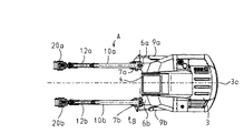
図1及び図2は、本発明の第1の実施の形態に係る双腕作業機械の一例である双腕型油圧ショベル200の外観を示す図である。図1は双腕型油圧ショベル200の側面図であり、図2は双腕型油圧ショベル200の上面図である。
1 and 2 are views showing the appearance of a double-armed
図1及び図2において、双腕型油圧ショベル200は、走行体1を備えた下部車体2と、この下部車体2上に旋回可能に設けられた上部旋回体3と、この上部旋回体3の前部中央付近に設けられた運転室4と、上部旋回体3の前部左右に上下、左右揺動自在に設けられた第1作業フロントA及び第2作業フロントBとを備えている。
1 and 2, a double-armed
第1作業フロントAは、上部旋回体3の前部右側に設けられた第1ブラケット6aと、この第1ブラケット6aに縦軸周りに左右揺動自在に取り付けられたスイングポスト7aと、このスイングポスト7aに上下揺動自在に取り付けられたブーム10aと、このブーム10aに上下揺動自在に取り付けられたアーム12aと、このアーム12aに上下回動自在に取り付けられた作業具20a(図中でばグラップル)と、スイングポスト7aと上部旋回体3とに連結され、スイングポスト7aを縦軸周りに左右方向に揺動させるスイングポストシリンダ9aと、スイングポスト7aとブーム10aに連結され、ブーム10aを上下方向に揺動させるブームシリンダ11aと、ブーム10aとアーム12aとに連結され、アーム12aを上下方向に揺動させるアームシリンダ13aと、アーム12aと作業具20aとに連結され、作業具20aを上下方向に回動させる作業具シリンダ15aとを有している。
The first work front A includes a first bracket 6a provided on the right side of the front portion of the
ここで、作業具20aは、作業機械の作業内容に応じて、図中で示したグラップルの他に、カッタ、ブレーカ、バケット、その他の作業具のいずれか1つに任意に交換可能である。
Here, the
第2作業フロントBは、上部旋回体3の前部左側に設けられている。これは、第1作業フロントAと同様に構成されており、同じ部材には符号の添字を「a」から「b」に変えて示すことにし、ここでは説明を省略する。
The second work front B is provided on the front left side of the
油圧ショベル200の運転室4内には、第1及び第2作業フロントA,Bをそれぞれ操作するための操作装置50a,50b(図3参照)と、作業領域演算(後述)の有効/無効を切り換える作業領域演算用スイッチ110(図4参照)が設けられている。
In the cab 4 of the
図3は、運転室4内に設けられた操作装置50a,50bを運転席49と共に示す斜視図である。
FIG. 3 is a perspective view showing the operation devices 50 a and 50 b provided in the cab 4 together with the
運転席49の左右両側には第1作業フロントA用の操作装置50a及び第2作業フロントB用の操作装置50bが設けられている。
On the left and right sides of the
操作装置50aは、運転席49の右側に設けられた操作アームブラケット51aと、その操作アームブラケット51aに揺動中心軸線73a周りに左右揺動自在に取り付けられ、第1作業フロントAの左右の揺動を指示する操作アーム52aと、この操作アーム52aに一体に揺動するように取り付けられたアームレスト53aとを備えている。アームレスト53aは、操作者の肘関節が位置する肘関節支持部77aを有し、操作アーム52a及びアームレスト53aは、アームレスト53aの肘関節支持部77aが操作アーム52aの揺動中心軸線73a上に位置するように操作アームブラケット51aに取り付けられている。操作アームブラケット51aは、操作者の体型に合わせて肘関節指示部77aの位置を調節するための肘関節位置調節装置78aを有している。
The operating device 50a is provided with an operating arm bracket 51a provided on the right side of the driver's
また、操作装置50aは、操作アーム52aの先端部分に上下前後に回動自在に取り付けられ、第1作業フロントAのブーム10a及びアーム12aの動作を指示する横置きの操作レバー54aと、この操作レバー54aの周囲に、操作レバー54aの回転中心軸線74a周りに回動自在に取り付けられ、作業具20aの回動を指示する作業具回動レバー55aと、操作レバー54aの先端部に取り付けられ、作業具20aの始動・停止を指示する作業具操作スイッチ56aとを備えている。
The operating device 50a is attached to the front end portion of the operating arm 52a so as to be rotatable up and down, and is provided with a horizontal operating lever 54a for instructing the operation of the boom 10a and the
また、操作装置50aは、操作アームブラケット51aに設けられ、操作アーム52aの揺動変位量を検出して信号(操作信号)を発信する操作アーム用変位検出器57aと、操作アーム52aに設けられ、操作レバー54aの上下方向の変位量を検出して操作信号を発信する操作レバー用上下方向変位検出器581aと、これと同様に前後方向の変位量を検出して操作信号を発信する操作レバー用前後方向変位検出器582aと、操作レバー54aに設けられ、作業具回動レバー55aの回転変位量を検出して操作信号を発信する作業具回動レバー用変位検出器59aと、作業具回動レバー55aに設けられ、作業具操作スイッチ56aの変位量を検出して操作信号を発信する作業具操作スイッチ用変位検出器60aとを有している。
The operating device 50a is provided on the operating arm bracket 51a, and is provided on the operating arm 52a and an operating arm displacement detector 57a that detects a swing displacement amount of the operating arm 52a and transmits a signal (operation signal). An operation lever vertical displacement detector 581a that detects the amount of displacement of the operation lever 54a in the vertical direction and transmits an operation signal, and an operation lever that similarly detects the amount of displacement in the front-rear direction and transmits the operation signal. A front / rear
操作装置50bは、運転席49の左側に設けられている。これは、操作装置50aと同様に構成されており、同じ部材には符号の添字を「a」から「b」に変えて示すことにし、ここでは説明を省略する。
The operating device 50 b is provided on the left side of the
図4は、第1及び第2作業フロントA,Bの制御系を示す機能ブロック図である。なお、図4における括弧内の符号は第2作業フロントBに対応する各変位検出器、各角度検出器及び駆動系を示している。 FIG. 4 is a functional block diagram showing a control system of the first and second work fronts A and B. In addition, the code | symbol in the parenthesis in FIG. 4 has shown each displacement detector corresponding to the 2nd work front B, each angle detector, and a drive system.
図4の制御系は、大きく分類して、運転室4内の操作装置50a,50bに設けられた前出の各変位検出器、作業領域演算用スイッチ110、第1及び第2作業フロントA,Bに設けられた各角度検出器(後述)からなる入力系と、これら入力系からの入力信号(操作信号、指示信号、検出信号)を基に所定の演算をして駆動信号を生成し出力する制御装置61と、制御装置61からの駆動信号を受け、第1及び第2作業フロントA,Bの各部を動作させる各駆動系(後述)からなる出力系とから構成されている。 The control system of FIG. 4 is roughly classified into the above-described displacement detectors, work area calculation switches 110, first and second work fronts A, provided in the operation devices 50a and 50b in the cab 4. Generates and outputs a drive signal by performing a predetermined calculation based on an input system composed of angle detectors (described later) provided in B and input signals (operation signal, instruction signal, detection signal) from these input systems. The control device 61 is configured to receive a drive signal from the control device 61, and an output system including each drive system (described later) that operates each part of the first and second work fronts A and B.
制御装置61の入力系としては、操作アーム52a,52bの揺動変位量をそれぞれ検出して信号(操作信号)を発信する操作アーム用変位検出器57a,57bと、操作レバー54a,54bの上下方向の変位量をそれぞれ検出して操作信号を発信する操作レバー用上下方向変位検出器581a,581bと、操作レバー54a,54bの前後方向の変位量をそれぞれ検出して操作信号を発信する操作レバー用前後方向変位検出器582a,582bと、作業具回動レバー55a,55bの回転変位量をそれぞれ検出して操作信号を発信する作業具回動レバー用変位検出器59a,59bと、作業具操作スイッチ56a,56bの変位量をそれぞれ検出して操作信号を発信する作業具操作スイッチ用変位検出器60a,60bと、作業領域演算(後述)の有効/無効を指示する信号(指示信号)を発信する作業領域演算用スイッチ110と、第1及び第2作業フロントA,Bのそれぞれのアーム12a,12bの角度を検出して信号(検出信号)を発信するアーム角度検出器69a,69bとが設けられている。
As an input system of the control device 61, displacement detectors 57a and 57b for detecting the swing displacement of the
また、制御装置61の出力系としては、上記スイングポストシリンダ9a,9bを駆動するスイングポストシリンダ駆動系64a,64bと、上記ブームシリンダ11a,11bを駆動するブームシリンダ駆動系63a,63bと、上記アームシリンダ13a,13bを駆動するアームシリンダ駆動系62a,62bと、上記作業具シリンダ15a,15bを駆動する作業具シリンダ駆動系65a,65bと、上記作業具20a,20bを駆動する作業具駆動系66a,66bとが設けられている。
The output system of the control device 61 includes swing post
制御装置61は、作業領域演算用スイッチ110、アーム角度検出器69a,69b、及び操作レバー用前後方向変位検出器582a,582bからの入力信号(操作信号)を基に作業領域演算を行う作業領域演算部61Fと、作業領域演算部61Fからの入力信号(演算結果)を基にアームシリンダ駆動系64a,64bへの駆動信号を生成する駆動信号生成部61Cと、操作アーム用変位検出器57a,57bからの入力信号を基にスイングポストシリンダ駆動系62a,62bへの駆動信号を生成する駆動信号生成部61Aと、操作レバー用上下方向変位検出器581a,581bからの入力信号を基にブームシリンダ駆動系63a,63bへの駆動信号を生成する駆動信号生成部161Bと、作業具回動レバー用変位検出器59a,59bからの入力信号を基に作業具シリンダ駆動系65a,65bへの駆動信号を生成する駆動信号生成部61Dと、作業具操作スイッチ用変位検出器60a,60bからの入力信号に基づいて作業具駆動系66a,66bへの駆動信号を生成する駆動信号生成部61Eとを有している。
The control device 61 performs a work area calculation based on input signals (operation signals) from the work
次に、図5及び図6を用いて、操作装置50a,50bの操作と第1及び第2作業フロントA,Bの動作の関係を説明する。図5は操作装置50a,50bの操作方向を示す図であり、図6は操作装置50a,50bの操作方向に対応する第1及び第2作業フロントA,Bの動作を示す図である。なお、第2作業フロントBについては図中に括弧書きの符号で示している。 Next, the relationship between the operation of the operation devices 50a and 50b and the operation of the first and second work fronts A and B will be described with reference to FIGS. FIG. 5 is a diagram illustrating the operation directions of the operation devices 50a and 50b, and FIG. 6 is a diagram illustrating the operations of the first and second work fronts A and B corresponding to the operation directions of the operation devices 50a and 50b. The second work front B is indicated by parenthesized symbols in the figure.
操作装置50a、50bを操作して第1作業フロントA及び第2作業フロントBを動かすには、操作者は運転席49に着座し、右腕の肘関節を操作アーム52a上のアームレスト53aの肘関節支持部77aに載せ、掌部で作業具回動レバー55aを把持し、親指を作業具操作スイッチ56aに掛ける。同様に、左腕の肘関節を操作アーム52b上のアームレスト53bの肘関節支持部77bに載せ、掌部で作業具回動レバー55bを把持し、親指を作業具操作スイッチ56bに掛ける。
To move the first work front A and the second work front B by operating the operation devices 50a and 50b, the operator sits on the driver's
この状態で、操作者が操作装置50a,50bの操作アーム52a,52bを例えば前腕部で左右揺動させる(図5のw参照)と、操作アーム用変位検出器57a,57bは、制御装置61のスイングポストシリンダ駆動系62a,62b用の駆動信号生成部61Aに操作信号を発信する。この操作信号を受けた駆動信号生成部61Aは、スイングポストシリンダ駆動系62a,62bに駆動信号を発信する。この駆動信号を受けたスイングポストシリンダ駆動系62a,62bは、スイングポストシリンダ9a,9bを伸縮させる。これにより、スイングポスト7a,7bは操作アーム52a,52bの変位方向と一致する方向に揺動される(図6のW参照)。
In this state, when the operator swings the operating
このとき、スイングポスト7a,7bの揺動速度は、操作アーム52a,52bの変位量と単純増加の関係、例えば比例関係にあり、操作アーム52a,52bの変位は、スイングポスト7a,7bの揺動を速度制御する。
At this time, the swing speed of the swing posts 7a and 7b is in a simple increase relationship, for example, a proportional relationship with the displacement amount of the
また、掌部で操作レバー54a,54bを上下方向に変位させる(図5のy参照)と、操作レバー用上下方向変位検出器581a,581bは、制御装置61のブームシリンダ駆動系63a,63b用の駆動信号生成部61Bに操作信号を発信する。この操作信号を受信した駆動信号生成部61Bは、ブームシリンダ駆動系63a,63bに駆動信号を発信する。この駆動信号を受けたブームシリンダ駆動系63a,63bは、ブームシリンダ11a,11bを伸縮させる。これにより、ブーム10a,10bが揺動される(図6のY参照)。
When the operating levers 54a and 54b are displaced in the vertical direction by the palm (see y in FIG. 5), the vertical displacement detectors 581a and 581b for the operating lever are used for the boom cylinder drive systems 63a and 63b of the control device 61. An operation signal is transmitted to the drive signal generation unit 61B. The drive signal generator 61B that has received this operation signal transmits a drive signal to the boom cylinder drive systems 63a and 63b. The boom cylinder drive systems 63a and 63b that have received this drive signal extend and contract the
このとき、ブーム10a,10bの揺動速度は、操作レバー54a,54bの上下方向(y方向)の変位量と単純増加の関係、例えば比例関係にあり、操作レバー54a,54bの上下方向の変位は、ブーム10a,10bの揺動を速度制御する。
At this time, the swinging speed of the
同様に、掌部で操作レバー54a,54bを前後方向に変位させる(図5のx参照)と、操作レバー用前後方向変位検出器582a,582b、及びアーム角度検出器69a,69bは、制御装置61の作業領域演算部61Fに信号を発信する。これらの信号を受信した作業領域演算部61Fは、作業領域演算用スイッチ110からの指示信号により作業領域演算を有効に切り換えた場合、操作レバー用前後方向変位検出器582a,582b、及びアーム角度検出器69a,69bからの入力信号を基に作業領域演算を行い、アームシリンダ駆動系64a,64b用の駆動信号生成部61Cに信号(演算結果)を発信する。この信号を受信した駆動信号生成部61Cは、アームシリンダ駆動系64a,64bに駆動信号を発信する。この駆動信号を受けたアームシリンダ駆動系64a,64bは、アームシリンダ13a,13bを伸縮させる。これにより、アーム12a,12bが揺動される(図6のX参照)。
Similarly, when the operation levers 54a, 54b are displaced in the front-rear direction by the palm (see x in FIG. 5), the operation lever front-rear
また、作業領域演算部61Fは、作業領域演算用スイッチ110からの指示信号により作業領域演算を無効に切り換えた場合、作業領域演算を行わず、操作レバー用前後方向変位検出器582a,582bからの操作信号をそのまま駆動信号生成部61Cに発信する。この操作信号を受信した駆動信号生成部61Cは、アームシリンダ駆動系64a,64bに駆動信号を発信し、アームシリンダ駆動系64a,64bは、アームシリンダ13a,13bを伸縮させる。これにより、アーム12a,12bが揺動される(図6のX参照)。このとき、アーム12a,12bの揺動速度は、操作レバー54a,54bの前後方向(x方向)の変位量と単純増加の関係、例えば比例関係にあり、操作レバー54a,54bの前後方向の変位は、アーム12a,12bの揺動を速度制御する。
In addition, when the work area calculation is switched to invalid by the instruction signal from the work
また、掌で作業具回動レバー55a,55bを回動中心軸線74a,74b回りに回動させる(図5のz参照)と、作業具回動レバー用変位検出器59a,59bは、制御装置61の作業具シリンダ駆動系65a,65b用の駆動信号生成部61Dに操作信号を発信する。この操作信号を受信した駆動信号生成部61Dは、作業具シリンダ駆動系65a,65bに駆動信号を発信する。この駆動信号を受けた作業具シリンダ駆動系65a,65bは、作業具シリンダ15a,15bを伸縮させる。これにより、作業具20a,20bが揺動される(図6のZ参照)。
Further, when the work tool turning levers 55a and 55b are turned around the turning center axes 74a and 74b with a palm (see z in FIG. 5), the work tool turning lever displacement detectors 59a and 59b are controlled by a control device. An operation signal is transmitted to the drive signal generator 61D for the work tool
このとき、作業具20a,20bの揺動速度は、作業具回動レバー55a,55bの変位量と単純増加の関係、例えば比例関係にあり、作業具回動レバー55a,55bの変位は、作業具20a,20bの揺動を速度制御する。
At this time, the swing speeds of the
また、指部で作業具操作スイッチ56a,56bを変位させると、作業具操作スイッチ用変位検出器60a,60bは、制御装置61の作業具駆動系66a,66b用の駆動信号生成部61Eに操作信号を発信する。この操作信号を受信した駆動信号生成部61Eは、作業具駆動系66a,66bに駆動信号を発信する。この駆動信号を受けた作業具駆動系66a,66bは、作業具20a,20bを駆動させる。例えば作業具20a,20bとして図1に示したグラップルを扱う場合には、作業具操作スイッチ56a,56bの操作に応じてグラップルが開閉される。
When the work tool operation switches 56a and 56b are displaced by the finger, the work tool operation
このとき、グラップル(作業具20a,20b)の開閉速度は作業具操作スイッチ56a,56bの変位量と単純増加の関係、例えば比例関係にあり、作業具操作スイッチ56a,56bの変位は作業具20a,20bの駆動を速度制御する。
At this time, the opening / closing speed of the grapples (
続いて、図7〜図14を用いて、制御装置61の作業領域演算部61Fの作業領域演算の処理内容を説明する。 Subsequently, processing contents of the work area calculation of the work area calculation unit 61F of the control device 61 will be described with reference to FIGS.
図7は、第1及び第2作業フロントA,Bにおけるアーム角度のとり方を示す図である。 FIG. 7 is a diagram showing how to set the arm angle in the first and second work fronts A and B. FIG.
図7に示すように、第1作業フロントAのブーム10aとアーム12aの角度(アーム角度)をθa、第2作業フロントBのブーム10bとアーム12bの角度(アーム角度)をθbと設定し、それらの角度の平均をアーム平均角度θc(=(θa+θb)/2)と設定する。このとき、アーム角度θa,θbの設定の仕方は、第1作業フロントAと第2作業フロントBで同様に設定すれば足りる。本実施の形態においては、第1作業フロントAのブーム10aの両端(スイングポスト7a、アーム12aとの連結支点)を通る線をブーム基準線101a、アーム12aの両端(ブーム10a、作業具20aとの連結支点)を通る線をアーム基準線121aと設定し、ブーム基準線101aに対してアーム基準線121aがなす角度をアーム角度θaと設定する。アーム角度θaはアーム12aが内側から外側に向かう方向を正方向とする。つまり、アーム12aがダンプ方向に駆動されるとアーム角度θaは増加する。第2作業フロントBについても同様にアーム角度θbを設定する。すなわち、第2作業フロントBのブーム10bの両端を通る線をブーム基準線101b、アーム12bの両端を通る線をアーム基準線121bと設定し、ブーム基準線101bに対してアーム基準線121bがなす角度をアーム角度θbと設定する。アーム角度θbもアーム12bが内側から外側に向かう方向を正方向とする。
As shown in FIG. 7, the angle (arm angle) between the boom 10a and the
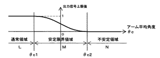
図8は、アーム平均角度θcと双腕作業機械の安定/不安定の関係を示した概念図である。 FIG. 8 is a conceptual diagram showing the relationship between the arm average angle θc and the stability / unstableness of the double-arm work machine.
図8において、横軸はアーム平均角度θcを表している。アーム平均角度θcが閾値θc2よりも小さい場合を双腕型油圧ショベル200が安定な状態(双腕作業機械安定)、アーム平均角度θcが閾値θc2よりも大きい場合を双腕型油圧ショベル200が不安定な状態(双腕作業機械不安定)と定義する。この閾値θc2の決め方は限定されないが、例えば、本実施の形態の双腕作業機械(双腕型油圧ショベル200)の安定性(静的バランス)が、この双腕作業機械と同クラスの単腕作業機械(同等のエンジン出力を有する単腕作業機械)において作業フロントを最大限に前方に伸ばした場合と同等の安定性となるときのアーム平均角度(或いはそれよりも小さなアーム平均角度)を閾値θc2とする。作業領域演算部61Fには、この閾値θc2が予め格納されており、双腕型油圧ショベル200が不安定となるアーム平均角度の範囲であるθc2≦θcの領域を不安定領域Nと定義する。
In FIG. 8, the horizontal axis represents the arm average angle θc. When the arm average angle θc is smaller than the threshold value θc2, the double-arm
一方、θc<θc2の領域においては、2台の作業フロントA,Bが停止した状態では双腕作業機が不安定な状態にはならない。しかし、この領域で2台の作業フロントA,Bを動作させる場合においても急停止させることが難しいこともある。このため、2台の作業フロントA,Bが作業機械安定の領域で操作されていても、不安定領域Nの近くで作業フロントA,Bが動作しアーム平均角度θcが増加する場合、その動作速度によっては2台の作業フロントA,Bのアーム平均角度θcが不安定領域Nに侵入し双腕作業機不安定となる恐れがある。そこで、不安定領域Nの内側に隣接する領域に、2台の作業フロントA,Bがの動作速度を減速させ、双腕作業機不安定となる前に停止させるための余裕を考慮して閾値θc1(<θc2)を設定する。作業領域演算部61Fには、この閾値θc1も予め格納されており、双腕型油圧ショベル200が上記不安定領域Nに隣接する設定のアーム平均角度の範囲であるθc1≦θc<θc2の領域を安定限界領域Mと定義する。
On the other hand, in the region of θc <θc2, the two-arm work machine does not become unstable when the two work fronts A and B are stopped. However, it may be difficult to stop suddenly even when operating two work fronts A and B in this region. For this reason, even if the two work fronts A and B are operated in the work machine stable region, if the work fronts A and B operate near the unstable region N and the arm average angle θc increases, the operation is performed. Depending on the speed, the arm average angle θc of the two work fronts A and B may enter the unstable region N and become unstable with the double-arm work machine. In view of this, in consideration of a margin for reducing the operating speed of the two work fronts A and B in an area adjacent to the inner side of the unstable area N and stopping the two-arm work machine before it becomes unstable, a threshold value is set. θc1 (<θc2) is set. The work area calculation unit 61F also stores this threshold value θc1 in advance, and sets an area of θc1 ≦ θc <θc2 that is a range of arm average angles set by the double-arm
θc<θc1の領域は、安定限界領域Mの内側に隣接する領域であり、2台の作業フロントA,Bの動作状態によらず双腕作業機が不安定になる恐れが無い通常領域Lと定義する。 The region of θc <θc1 is a region adjacent to the inside of the stability limit region M, and is a normal region L in which the two-arm work machine is not likely to become unstable regardless of the operating states of the two work fronts A and B. Define.
ここで、アーム平均角度θcは2台の作業フロントA,Bの姿勢による機体不安定性の評価値である安定判別値であり、閾値θc2は安定判別基準値である。 Here, the arm average angle θc is a stability determination value that is an evaluation value of airframe instability due to the postures of the two work fronts A and B, and the threshold θc2 is a stability determination reference value.
図9は、作業領域演算部61Fの作業領域演算が有効であり、かつ第1及び第2作業フロントA,Bのアーム平均角度θcが増加する場合におけるアーム平均角度θcと作業領域演算部61Fの出力信号(演算結果)の大きさの関係の一例を表す図である。 FIG. 9 shows that when the work area calculation of the work area calculation unit 61F is effective and the arm average angle θc of the first and second work fronts A and B increases, the arm average angle θc and the work area calculation unit 61F It is a figure showing an example of the relationship of the magnitude | size of an output signal (calculation result).
図9において、横軸はアーム平均角度θc、縦軸は入力信号に対する出力信号を比の形で表している。すなわち、出力信号は入力信号で除することにより無次元化してある。図9の例では、アーム平均角度θcが通常領域Lにある場合は出力信号は1であり、入力信号がそのまま出力信号(演算結果)として出力される。アーム平均角度θcが安定限界領域Mにある場合は出力信号はα(0<α<1)であり、入力信号に一定の値αを乗じることにより減じられた信号(演算結果)が出力される。アーム平均角度θcが不安定領域Nにある場合は出力信号は0であり、入力信号に0(ゼロ)を乗じることにより得られた信号が演算結果となり、したがって、信号は出力されない。 In FIG. 9, the horizontal axis represents the arm average angle θc, and the vertical axis represents the output signal relative to the input signal in the form of a ratio. That is, the output signal is made dimensionless by dividing by the input signal. In the example of FIG. 9, when the arm average angle θc is in the normal region L, the output signal is 1, and the input signal is output as it is as an output signal (calculation result). When the arm average angle θc is in the stability limit region M, the output signal is α (0 <α <1), and a signal (calculation result) reduced by multiplying the input signal by a certain value α is output. . When the arm average angle θc is in the unstable region N, the output signal is 0, and the signal obtained by multiplying the input signal by 0 (zero) is the calculation result, and therefore no signal is output.
次に、このような作業領域演算を行う作業領域演算部61Fの出力信号の演算手順を各領域毎に説明する。 Next, the calculation procedure of the output signal of the work area calculation unit 61F that performs such work area calculation will be described for each area.
(1)通常領域L
第1及び第2作業フロントA,Bのアーム平均角度θcが通常領域L、つまり安定限界領域Mの外側にある場合、作業領域演算部61Fは、操作レバー用前後方向変位検出器582a,582bからの入力信号をそのまま出力信号として駆動信号生成部61Cに出力する。このときの出力信号(演算結果)は2つの作業フロントA,Bのアーム平均角度θcが増加である場合と減少である場合で同じである。(1) Normal area L
When the average arm angle θc of the first and second work fronts A and B is outside the normal region L, that is, outside the stability limit region M, the work region calculation unit 61F is operated by the operation lever
(2)安定限界領域M
第1及び第2作業フロントA,Bのアーム平均角度θcが安定限界領域Mにあり、かつ操作レバー用前後方向変位検出器582a,582bからの入力信号が、アーム平均角度θcが増加する信号の場合、作業領域演算部61Fは、操作レバー用前後方向変位検出器582a,582bからの入力信号にα(0<α<1)を乗じた信号(減じた信号)を出力信号(演算結果)として駆動信号生成部61Cに出力する。(2) Stability limit region M
The arm average angle θc of the first and second work fronts A and B is in the stability limit region M, and the input signal from the operation lever
一方、第1及び第2作業フロントA,Bのアーム平均角度θcが安定限界領域Mにあり、かつ操作レバー用前後方向変位検出器582a,582bからの入力信号が、アーム平均角度θcが減少する信号の場合、作業領域演算部61Fは、操作レバー用前後方向変位検出器582a,582bからの入力信号をそのまま出力信号(演算結果)として駆動信号生成部61Cに出力する。
On the other hand, the arm average angle θc of the first and second work fronts A and B is in the stability limit region M, and the input signal from the operation lever
(3)不安定領域N
第1及び第2作業フロントA,Bのアーム平均角度θcが不安定領域Nにあり、かつ操作レバー用前後方向変位検出器582a,582bからの入力信号が、アーム平均角度θcが増加する信号の場合、作業領域演算部61Fは、操作レバー用前後方向変位検出器581a,582bからの入力信号に0(ゼロ)を乗じた信号(減じた信号)を出力信号(演算結果)とする。したがって、駆動信号生成部61Cに信号は出力されない。(3) Unstable region N
The arm average angle θc of the first and second work fronts A and B is in the unstable region N, and the input signal from the operation lever
一方、第1及び第2作業フロントA,Bのアーム平均角度θcが安定限界領域Mにあり、かつ操作レバー用前後方向変位検出器582a,582bからの入力信号が、アーム平均角度θcが減少する信号の場合、作業領域演算部61Fは、操作レバー用前後方向変位検出器582a,582bからの入力信号をそのまま出力信号(演算結果)として駆動信号生成部61Cに出力する。
On the other hand, the arm average angle θc of the first and second work fronts A and B is in the stability limit region M, and the input signal from the operation lever
ここで、前述したように作業領域演算部61Fの作業領域演算は、作業領域演算用スイッチ110により有効/無効が切り換えられる。作業領域演算用スイッチ110により作業領域演算が有効に切り換えられた場合の作業領域演算部61Fの演算結果(出力信号)は上述の通りである。
Here, as described above, the work area calculation of the work area calculation unit 61F is switched between valid / invalid by the work
逆に、作業領域演算スイッチ110により作業領域演算が無効に切り換えられた場合、作業領域演算部61は作業領域演算を行わない。したがって作業領域演算部61Fは、操作レバー用前後方向変位検出器582a,582bからの入力信号をそのまま出力信号として駆動信号生成部61Cに出力する。このときの出力信号は、2つの作業フロントA,Bのアーム平均角度θcの状態によらない。
Conversely, when the work area calculation is switched to invalid by the work
以上のように構成した本実施の形態の効果を説明する。 The effect of the present embodiment configured as described above will be described.
双腕作業機械(双腕型油圧ショベル200)の2台の作業フロントA,Bの合計重量を、例えば、この双腕作業機械と同クラスの単腕作業機械(同等のエンジン出力を有する単腕作業機械)の作業フロントの重量と同等となるように構成すると、この双腕作業機械の安定性(静的バランス)は同クラスの単腕作業機械と同等となる。しかし、双腕作業機械の2台の作業フロントA,Bの合計出力を向上させると、作業フロントの出力と強度、及び強度と重量はほぼ比例関係となっているため、双腕作業機械の2台の作業フロントA,Bの合計重量が増加し、同クラスの単腕作業機械と比較して安定性が悪化する恐れがある。本実施の形態においては、2台の作業フロントA,Bのアーム平均角度θcが閾値θc2以上となる領域を不安定領域Nと設定し、アーム平均角度θcが不安定領域Nに入らないように2台の作業フロントA,Bの動作を制御する。したがって、閾値θc2を同クラスの単腕作業機械の安定性を考慮した値に設定することにより、双腕作業機械と同クラスの単腕作業機械と同等の安定性を確保することができ、2台の作業フロントA,Bの出力向上に伴う安定性の悪化を抑制することができる。 The total weight of the two work fronts A and B of the double-arm work machine (double-arm hydraulic excavator 200) is, for example, a single-arm work machine of the same class as this double-arm work machine (single-arm having the same engine output) When configured to be equivalent to the weight of the work front of the work machine), the stability (static balance) of the double-arm work machine is equivalent to that of the single-arm work machine of the same class. However, if the total output of the two work fronts A and B of the double-arm work machine is improved, the output and strength of the work front, and the strength and weight are approximately proportional to each other. The total weight of the work fronts A and B of the platform increases, and the stability may be deteriorated as compared with a single-arm work machine of the same class. In the present embodiment, a region where the arm average angle θc of the two work fronts A and B is equal to or greater than the threshold value θc2 is set as an unstable region N so that the arm average angle θc does not enter the unstable region N. The operation of the two work fronts A and B is controlled. Therefore, by setting the threshold value θc2 to a value that considers the stability of the single-arm work machine of the same class, it is possible to ensure the same stability as the double-arm work machine and the single-arm work machine of the same class. The deterioration of the stability accompanying the output improvement of the work fronts A and B of a stand can be suppressed.
また、不安定領域Nの内側に隣接する安定限界領域Mを設定し、安定限界領域Mにおいてアーム平均角度θcが不安定領域Nに近付く場合に、作業フロントA,Bの動作速度を(制限)させるので、作業フロントA,Bを緩やかに停止させることができる。 Further, when the stability limit region M adjacent to the inside of the unstable region N is set, and the arm average angle θc approaches the unstable region N in the stability limit region M, the operation speed of the work fronts A and B is (limited). Therefore, the work fronts A and B can be stopped gently.
さらに、2台の作業フロントA,Bのアーム角度平均値θcを基に作業フロントA,Bの動作を制御するので、一方の作業フロントのアーム角度を最小にすると、他方の片方の作業フロントの作業領域を最大限に活用することができる。 Further, since the operation of the work fronts A and B is controlled based on the arm angle average value θc of the two work fronts A and B, when the arm angle of one work front is minimized, the work front of the other work front is You can make the most of your work area.
なお、本実施の形態においては、2台の作業フロントA,Bのアーム平均角度θcが安定限界領域Mにあり、かつ操作レバー用前後方向変位検出器582a,582bからの入力信号が、アーム平均角度θcが減少する信号の場合、作業領域演算部61Fは、操作レバー用前後方向変位検出器582a,582bからの入力信号をそのまま出力信号(演算結果)として駆動信号生成部61Cに出力するように構成したがこれに限られず、例えば、操作レバー用前後方向変位検出器582a,582bからの入力信号にαを乗じた信号を出力信号(演算結果)として駆動信号生成部61Cに出力するよう構成しても良い。
In the present embodiment, the arm average angle θc of the two work fronts A and B is in the stability limit region M, and the input signals from the operating lever
本発明の第1の実施の形態の他の例を図10を用いて説明する。 Another example of the first embodiment of the present invention will be described with reference to FIG.
図10は、第1及び第2作業フロントA,Bのアーム平均角度θcが増加する場合におけるアーム平均角度θcと作業領域演算部61Fの出力信号(演算結果)の大きさの関係の他の例を表す図である。図10における横軸、及び縦軸は図9と同様である。 FIG. 10 shows another example of the relationship between the arm average angle θc and the magnitude of the output signal (calculation result) of the work area calculation unit 61F when the arm average angle θc of the first and second work fronts A and B increases. FIG. The horizontal and vertical axes in FIG. 10 are the same as those in FIG.
すなわち、図10に示した例では、安定限界領域Mにおける出力信号が、不安定領域Nに近付くにつれて1から0(ゼロ)まで連続的に減じられるように設定されており、特に本例では不連続点の無い非線形曲線によって定義されている。この場合、第1及び第2作業フロントA,Bのアーム平均角度θcが不安定領域に近付くほどアーム12a,12bの駆動速度が抑制され、図9に示した例に比べ、アームシリンダ13a,13bを緩やかに停止させることが可能となる。また、本例のように不連続点を持たない非線形曲線でアーム平均角度θcと出力信号(演算結果)との関係を定義することにより、よりスムースにアーム12a,12bの動作を停止することができる。
That is, in the example shown in FIG. 10, the output signal in the stability limit region M is set so as to be continuously reduced from 1 to 0 (zero) as it approaches the unstable region N. It is defined by a non-linear curve with no continuous points. In this case, as the arm average angle θc of the first and second work fronts A and B approaches the unstable region, the drive speed of the
なお、図10に示した曲線(アーム平均角度θcと作業領域演算部61Fの出力信号(演算結果)の大きさの関係)を例えば放物線、又は円弧によって定義しても良い。 Note that the curve shown in FIG. 10 (the relationship between the arm average angle θc and the magnitude of the output signal (calculation result) of the work area calculation unit 61F) may be defined by a parabola or an arc, for example.
本発明の第1の実施の形態のさらに他の例を図11を用いて説明する。 Still another example of the first embodiment of the present invention will be described with reference to FIG.
図11は、第1及び第2作業フロントA,Bのアーム平均角度θcが増加する場合におけるアーム平均角度θcと作業領域演算部61Fの出力信号(演算結果)の大きさとの関係のさらに他の例を表す図である。図11における横軸、及び縦軸は図9と同様である。 FIG. 11 shows still another relationship between the arm average angle θc and the magnitude of the output signal (calculation result) of the work area calculation unit 61F when the arm average angle θc of the first and second work fronts A and B increases. It is a figure showing an example. The horizontal and vertical axes in FIG. 11 are the same as those in FIG.
すなわち、図11に示した例においても、安定限界領域Mにおける出力信号が、不安定領域Nに近付くにつれて1から0(ゼロ)まで連続的に減じられるように設定されている。ただし、本例では一定の傾きの線形直線により定義されており、さらに、通常領域Lと安定限界領域Mの出力信号との接続点及び安定限界領域Mと不安定領域Nの出力信号の接続点が不連続点となっている。この場合においても、第1及び第2作業フロントA,Bのアーム平均角度θcが不安定領域に近付くほどアーム12a,12bの駆動速度が抑制され、図9に示した例に比べ、アームシリンダ13a,13bを緩やかに停止させることが可能となる。
That is, in the example shown in FIG. 11 as well, the output signal in the stability limit region M is set to be continuously reduced from 1 to 0 (zero) as it approaches the unstable region N. However, in this example, it is defined by a linear line having a constant slope, and further, the connection point between the output signal of the normal region L and the stability limit region M and the connection point of the output signal of the stability limit region M and the unstable region N. Is a discontinuity point. Even in this case, as the arm average angle θc of the first and second work fronts A and B approaches the unstable region, the driving speed of the
本発明の第1の実施の形態のさらに他の例を図12〜図14を用いて説明する。 Still another example of the first embodiment of the present invention will be described with reference to FIGS.
図12〜図14は、第1及び第2作業フロントA,Bのアーム角度の平均値θcが増加する場合におけるアーム平均角度θcと作業領域演算部61Fの出力信号(演算結果)の大きさの関係の変形例を表す図である。図12〜図14に示した例では、横軸は図9と同様にアーム平均角度θcを表しているが、縦軸は出力信号の上限値を表している。 12 to 14 show the magnitude of the arm average angle θc and the output signal (calculation result) of the work area calculation unit 61F when the average value θc of the arm angles of the first and second work fronts A and B increases. It is a figure showing the modification of a relationship. In the examples shown in FIGS. 12 to 14, the horizontal axis represents the arm average angle θc as in FIG. 9, but the vertical axis represents the upper limit value of the output signal.
すなわち、図9〜図11に示した例が、安定限界領域Mにおいて入力信号に係数を乗ずることで出力信号を算出し、アーム駆動速度を減じていたのに対し、図12〜図14に示した例では、アーム駆動速度の上限値を各図のように設定し、安定限界領域Mにおける作業フロントA,Bのアーム12a,12bの動作速度を制限することで動作速度を減じるものである。つまり、どれだけ操作量が大きくても出力信号は上限値以内に抑えられる。このようにしても図9〜図11とほぼ同様の効果が得られる。
That is, in the example shown in FIGS. 9 to 11, the output signal is calculated by multiplying the input signal by a coefficient in the stability limit region M, and the arm driving speed is reduced. In this example, the upper limit value of the arm driving speed is set as shown in each figure, and the operating speed is reduced by limiting the operating speed of the
なお、図13に示した曲線(アーム平均角度θcと作業領域演算部61Fの出力信号の大きさの関係)を例えば放物線、又は円弧によって定義しても良い。 The curve shown in FIG. 13 (the relationship between the arm average angle θc and the magnitude of the output signal of the work area calculation unit 61F) may be defined by a parabola or an arc, for example.
本発明の第2の実施の形態を図15〜図17を用いて説明する。 A second embodiment of the present invention will be described with reference to FIGS.
第1の実施形態ではアーム平均角度θcで不安定領域Nや安定限界領域M、通常領域Lを定義してアーム平均角度θcを基に2台の作業フロントA,Bの動作を制御したのに対し、本実施形態ではアーム12a,12bの水平方向座標の平均値で不安定領域N、安定限界領域M、及び通常領域Lを定義し、アーム12a,12bの水平方向座標の平均値を基に2台作業フロントA,Bの動作を制御して、2台の作業フロントA,Bの安定性の悪化を抑制している。なお、2台の作業フロントA,Bのアーム12a,12bそれぞれの水平方向の座標は、上部旋回体3に対するブーム10a,10bの相対角度(ブーム角度)とブーム10a,10bに対するアーム12a,12bの相対角度(アーム角度)を基に算出される。
In the first embodiment, although the unstable region N, the stability limit region M, and the normal region L are defined by the arm average angle θc and the operations of the two work fronts A and B are controlled based on the arm average angle θc. On the other hand, in this embodiment, the unstable region N, the stability limit region M, and the normal region L are defined by the average values of the horizontal coordinates of the
図15は、本実施の形態における第1及び第2作業フロントA,Bの制御系を示す機能ブロック図である。なお、図15において、第2作業フロントBについては図中に括弧書きの符号で示している。図中、図4に示した部材と同様のものには同じ符号を付し、説明を省略する。 FIG. 15 is a functional block diagram showing a control system of the first and second work fronts A and B in the present embodiment. In FIG. 15, the second work front B is indicated by parenthesized symbols in the drawing. In the figure, the same members as those shown in FIG.
図15の制御系は、第1の実施の形態の入力系にブーム角度検出器68a,68bを加え、さらに、制御装置61に換えて制御装置261を備えている。つまり、本実施の形態の制御系は、第1の実施の形態と同様に、運転室4内の操作装置50a,50bに設けられた前出の各変位検出器、作業領域演算用スイッチ110、第1及び第2作業フロントA,Bに設けられた各角度検出器からなる入力系と、これら入力系からの入力信号(操作信号、指示信号、検出信号)を基に所定の演算をして駆動信号を生成し出力する制御装置261と、制御装置261からの駆動信号を受け、第1及び第2作業フロントA,Bの各部を動作させる各駆動系からなる出力系とから構成されている。
The control system of FIG. 15 includes boom angle detectors 68 a and 68 b in addition to the input system of the first embodiment, and further includes a
制御装置261の入力系としては、第1の実施の形態と同様の構成である操作アーム用変位検出器57a,57b、操作レバー用上下方向変位検出器581a,581b、操作レバー用前後方向変位検出器582a,582b、作業具回動レバー用変位検出器59a,59b、作業具操作スイッチ用変位検出器60a,60b、作業領域演算用スイッチ110、及びアーム角度検出器69a,69bに加えて、第1及び第2作業フロントA,Bのそれぞれのブームの角度を検出して信号(検出信号)を発信するブーム角度検出器68a,68bが設けられている。
As an input system of the
制御装置261の出力系としては、第1の実施の形態と同様の構成であるスイングポストシリンダ駆動系64a,64b、ブームシリンダ駆動系63a,63b、アームシリンダ駆動系62a,62b、作業具シリンダ駆動系65a,65b、及び作業具駆動系66a,66bが設けられている。
As an output system of the
制御装置261は、作業領域演算用スイッチ110、アーム角度検出器69a,69b、操作レバー用前後方向変位検出器582a,582b、操作レバー用上下方向変位検出器581a,581b、及びブーム角度検出器68a,68bからの入力信号(操作信号)を基に作業領域演算を行う作業領域演算部261Fと、作業領域演算部261Fからの入力信号(演算結果)を基にアームシリンダ駆動系64a,64bへの駆動信号を生成する駆動信号生成部61Cと、同じく作業領域演算部261Fからの入力信号を基にブームシリンダ駆動系63a,63bへの駆動信号を生成する駆動信号生成部61Bと、操作アーム用変位検出器57a,57bからの入力信号を基にスイングポストシリンダ駆動系62a,62bへの駆動信号を生成する駆動信号生成部61Aと、作業具回動レバー用変位検出器59a,59bからの入力信号を基に作業具シリンダ駆動系65a,65bへの駆動信号を生成する駆動信号生成部61Dと、作業具操作スイッチ用変位検出器60a,60bからの入力信号に基づいて作業具駆動系66a,66bへの駆動信号を生成する駆動信号生成部61Eとを有している。
The
続いて、図16及び図17を用いて、制御装置261の作業領域演算部261Fの作業領域演算の処理内容を説明する。
Subsequently, processing contents of the work area calculation of the work
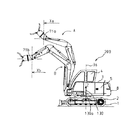
図16は、本実施の形態における双腕型油圧ショベル200の外観を示す側面図であって、第1及び第2作業フロントA,Bにおけるアーム水平方向座標のとり方を示す図である。
FIG. 16 is a side view showing the external appearance of the double-armed
図16に示すように、基準座標系130を設定する。基準座標系130は、上部旋回体3の旋回中心軸3a上において上部旋回体3と各車体2の接続部を原点130aとし、旋回軸3aに沿ってZ軸、このZ軸に垂直にかつ上部旋回体3の前後方向にX軸を設定する。また、第1及び第2作業フロントA,Bの作業具20a,20bが接続されている一端をそれぞれアーム先端71a,71bとする。このようにして設定した基準座標系130の原点130aと第1作業フロントAのアーム12aのアーム先端71aの水平距離をアーム水平方向座標Xa、原点130aと第2作業フロントBのアーム12bのアーム先端71bの水平距離をアーム水平方向座標Xbと定義し、このアーム水平方向座標Xa,Xbの平均をアーム水平方向座標平均値Xc(=(Xa+Xb)/2)と定義する。アーム水平方向座標Xa,Xbは、上部旋回体3の前方を正方向とする。つまり、アーム12a,12bがダンプ方向に駆動されるとアーム水平方向座標Xa,Xbは増加する。
As shown in FIG. 16, a reference coordinate
図17は、アーム水平方向座標平均値Xcと双腕作業機械の安定/不安定の関係を示した概念図である。 FIG. 17 is a conceptual diagram showing the relationship between the arm horizontal direction coordinate average value Xc and the stability / unstableness of the dual-arm work machine.
図17において、横軸はアーム水平方向座標平均値Xcを表している。アーム水平方向座標平均値Xcが閾値Xc2よりも小さい場合を双腕型油圧ショベル200が安定な状態(双腕作業機械安定)、アーム水平方向座標平均値Xcが閾値Xc2よりも大きい場合を双腕型油圧ショベル200が不安定な状態(双腕作業機械不安定)と定義する。この閾値Xc2の決め方は限定されないが、例えば、本実施の形態の双腕作業機械(双腕型油圧ショベル200)の安定性(静的バランス)が、この双腕作業機械と同クラスの単腕作業機械(同等のエンジン出力を有する単腕作業機械)と同等の安定性となるときのアーム水平方向座標平均値(或いはそれよりも小さなアーム水平方向座標平均値)を閾値Xc2とする。作業領域演算部261Fには、この閾値Xc2が予め格納されており、双腕型油圧ショベル200が不安定となるアーム水平方向座標平均値の範囲であるXc2≦Xcの領域を不安定領域Nと定義する。
In FIG. 17, the horizontal axis represents the arm horizontal direction coordinate average value Xc. When the arm horizontal coordinate average value Xc is smaller than the threshold value Xc2, the double-arm
一方、Xc<Xc2の領域においては、2台の作業フロントA,Bが停止した状態では双腕作業機が不安定にならない。しかし、この領域で2台の作業フロントA,Bを動作させる場合においても急停止させることが難しいこともある。このため、2台の作業フロントA,Bが作業機械安定の領域で操作されていても、不安定領域Nの近くで作業フロントA,Bが動作しアーム水平方向座標平均値Xcが増加する場合、その動作速度によっては2台の作業フロントA,Bのアーム水平方向座標平均値Xcが不安定領域Nに侵入し双腕作業機が不安定となる恐れがある。そこで、不安定領域Nの内側に隣接した領域に、2台の作業フロントA,Bの動作速度を減速させ、双腕作業機不安定となる前に停止させるための余裕を考慮して閾値Xc1(<Xc2)を設定する。作業領域演算部261Fには、この閾値Xc1も予め格納されており、双腕型油圧ショベル200が上記不安定領域Nに隣接する設定のアーム水平方向座標平均値の範囲であるXc1≦Xc<Xc2の領域を安定限界領域Mと定義する。
On the other hand, in the region of Xc <Xc2, the two-arm work machine does not become unstable when the two work fronts A and B are stopped. However, it may be difficult to stop suddenly even when operating two work fronts A and B in this region. For this reason, even if the two work fronts A and B are operated in a stable area of the work machine, the work fronts A and B operate near the unstable area N and the arm horizontal coordinate average value Xc increases. Depending on the operation speed, the arm horizontal coordinate average value Xc of the two work fronts A and B may enter the unstable region N and the two-arm work machine may become unstable. Therefore, the threshold Xc1 is set in consideration of a margin for reducing the operating speed of the two work fronts A and B in an area adjacent to the inner side of the unstable area N and stopping the two-arm work machine before it becomes unstable. (<Xc2) is set. This threshold value Xc1 is also stored in advance in the work
Xc<Xc1の領域は、2台の作業フロントA,Bの動作状態によらず双腕作業機不安定になる恐れが無い通常領域Lと定義する。 The region of Xc <Xc1 is defined as a normal region L in which there is no possibility that the two-arm work machine becomes unstable regardless of the operating states of the two work fronts A and B.
なお、アーム水平方向座標平均値Xcは2つの作業フロントA,Bの姿勢による機体不安定性の評価値である安定判別値であり、閾値Xc2は安定判別基準値である。 The arm horizontal direction coordinate average value Xc is a stability determination value that is an evaluation value of the instability of the vehicle body by the postures of the two work fronts A and B, and the threshold value Xc2 is a stability determination reference value.
ここで、本実施の形態において、作業領域演算部261Fの作業領域演算が有効であり、かつ第1及び第2作業フロントA,Bのアーム水平方向座標平均値Xcが増加する場合におけるアーム水平方向座標平均値Xcと作業領域演算部261Fの演算結果(出力信号)の関係は、本発明の第1の実施の形態における図9に示した関係と同様である。但し、図9において、閾値θc1,θc2を閾値Xc1,Xc2、アーム平均角度θcをアーム水平方向座標平均値Xcにそれぞれ置き換える。すなわち、作業領域演算部261Fの出力信号は、アーム水平方向座標平均値Xcが通常領域Lにある場合は出力信号は1であり、入力信号がそのまま出力信号(演算結果)として出力される。アーム水平方向座標平均値Xcが安定限界領域Mにある場合はα(0<α<1)であり、入力信号に一定の値αを乗じることにより減じられた信号(演算結果)が出力される。アーム水平方向座標平均値Xcが不安定領域Nにある場合、出力信号は0であり、入力信号に0(ゼロ)を乗じることにより得られた信号が演算結果となり、従って信号は出力されない。
Here, in the present embodiment, the work area calculation in the work
次に、作業領域演算部261Fの出力信号の演算手順を各領域毎に説明する。
Next, the calculation procedure of the output signal of the work
(1)通常領域L
第1及び第2作業フロントA,Bのアーム水平方向座標平均値Xcが通常領域L、つまり安定限界領域Mの外側にある場合、作業領域演算部261Fは、操作レバー用前後方向変位検出器582a,582bからの入力信号をそのまま出力信号として駆動信号生成部61Cに出力し、操作レバー用上下方向変位検出器581a,581bからの入力信号をそのまま駆動信号生成部61Bに出力する。このときの出力信号(演算結果)は2つの作業フロントA,Bのアーム水平方向座標平均値Xcが増加である場合と減少である場合で同じである。(1) Normal area L
When the arm horizontal direction coordinate average value Xc of the first and second work fronts A and B is outside the normal area L, that is, outside the stability limit area M, the work
(2)安定限界領域M
第1及び第2作業フロントA,Bのアーム水平方向座標平均値Xcが安定限界領域Mにあり、かつ操作レバー用前後方向変位検出器582a,582b及び操作レバー上下方向変位検出器581a,581bからの入力信号が、アーム水平方向座標平均値Xcが増加する信号の場合、作業領域演算部261Fは、操作レバー用前後方向変位検出器582a,582bからの入力信号にαを乗じた信号を出力信号(演算結果)として駆動信号生成部61Cに出力し、操作レバー用上下方向変位検出器581a,581bからの入力信号にαを乗じた信号を出力信号(演算結果)として駆動信号生成部61Bに出力する。(2) Stability limit region M
The arm horizontal direction coordinate average value Xc of the first and second work fronts A and B is in the stability limit region M, and from the operation lever
一方、第1及び第2作業フロントA,Bのアーム水平方向座標平均値Xcが安定限界領域Mにあり、かつ操作レバー用前後方向変位検出器582a,582b及び操作レバー上下方向変位検出器581a,581bからの入力信号が、アーム水平方向座標平均値Xcが減少する信号の場合、作業領域演算部261Fは、操作レバー用前後方向変位検出器582a,582bからの入力信号をそのまま出力信号(演算結果)として駆動信号生成部61Cに出力し、操作レバー上下方向変位検出未581a,581bからの入力信号をそのまま出力信号(演算結果)として駆動信号生成部61Bに出力する。
On the other hand, the arm horizontal coordinate average value Xc of the first and second work fronts A and B is in the stability limit region M, and the operation lever
(3)不安定領域N
第1及び第2作業フロントA,Bのアーム水平方向座標平均値Xcが不安定領域Nにあり、かつ操作レバー用前後方向変位検出器582a,582b及び操作レバー用上下方向変位検出器581a,581bからの入力信号が、アーム水平方向座標平均値Xcが増加する信号の場合、作業領域演算部261Fは、操作レバー用前後方向変位検出器581a,582bからの入力信号に0(ゼロ)を乗じた信号を出力信号(演算結果)とする。したがって、駆動信号生成部61C及び駆動信号生成部61Bに信号は出力されない。(3) Unstable region N
The arm horizontal direction coordinate average value Xc of the first and second work fronts A and B is in the unstable region N, and the operation lever
一方、第1及び第2作業フロントA,Bのアーム水平方向座標平均値Xcが安定限界領域Mにあり、かつ操作レバー用前後方向変位検出器582a,582b及び操作レバー用上下方向変位検出器581a,581bからの入力信号が、アーム水平方向座標平均値Xcが減少する信号の場合、作業領域演算部261Fは、操作レバー用前後方向変位検出器582a,582bからの入力信号をそのまま出力信号(演算結果)として駆動信号生成部61Cに出力し、操作レバー用上下方向変位検出器581a,581bからの入力信号をそのまま出力信号(演算結果)として駆動信号生成部61Bに出力する。
On the other hand, the arm horizontal coordinate average value Xc of the first and second work fronts A and B is in the stability limit region M, and the operation lever
ここで、前述したように作業領域演算部261Fの作業領域演算は、作業領域演算用スイッチ110により有効/無効が切り換えられる。作業領域演算用スイッチ110により作業領域演算が有効に切り換えられた場合の作業領域演算部261Fの演算結果(出力信号)は上述の通りである。
Here, as described above, the work area calculation of the work
逆に、作業領域演算スイッチ110により作業領域演算が無効に切り換えられた場合、作業領域演算部261Fは作業領域演算を行わない。したがって作業領域演算部261Fは、操作レバー用前後方向変位検出器582a,582bからの入力信号をそのまま出力信号として駆動信号生成部61Cに出力し、操作レバー用上下方向変位検出器581a,581bからの入力信号をそのまま出力信号として駆動信号生成部61Bに出力する。このときの出力信号は、2つの作業フロントA,Bのアーム水平方向座標平均値Xcの状態によらない。
Conversely, when the work area calculation is switched to invalid by the work
以上のように構成した本実施の形態においても、本発明の第1の実施の形態と同様の効果を得ることが出来る。 Also in the present embodiment configured as described above, the same effects as those of the first embodiment of the present invention can be obtained.
なお、本実施の形態においては、2台の作業フロントA,Bのアーム水平方向座標平均値Xcが安定限界領域Mにあり、かつ操作レバー用前後方向変位検出器582a,582b及び操作レバー上下方向変位検出器581a,581bからの入力信号が、アーム水平方向座標平均値Xcが減少する信号の場合、作業領域演算部261Fは、操作レバー用前後方向変位検出器582a,582bからの入力信号をそのまま出力信号(演算結果)として駆動信号生成部61Cに出力し、操作レバー上下方向変位検出未581a,581bからの入力信号をそのまま出力信号(演算結果)として駆動信号生成部61Bに出力するように構成したがこれに限られず、例えば、操作レバー用前後方向変位検出器582a,582b及び操作レバー上下方向変位検出器581a,581bからの入力信号にαを乗じた信号を出力信号(演算結果)として駆動信号生成部61C及び駆動信号生成部61Bに出力するよう構成しても良い。
In the present embodiment, the arm horizontal coordinate average value Xc of the two work fronts A and B is in the stability limit region M, and the operation lever
また、作業領域演算部261Fの作業領域演算が有効であり、かつ第1及び第2作業フロントA,Bのアーム水平方向座標平均値Xcが増加する場合におけるアーム水平方向座標平均値Xcと作業領域演算部261Fの演算結果(出力信号)の関係が、本発明の第1の実施の形態における図9に示した関係と同様である場合を説明したが、これに限られず、例えば図10〜図14に示した関係と同様であっても良い。この場合においても第1の実施の形態と同様の効果が得られる。
Further, when the work area calculation of the work
本発明の第3の実施の形態を図18〜図20を用いて説明する。 A third embodiment of the present invention will be described with reference to FIGS.
第1の実施形態ではアーム平均角度θcで不安定領域Nや安定限界領域M、通常領域Lを定義してアーム平均角度θcを基に2台の作業フロントA,Bの動作を制御したのに対し、本実施形態では第1及び第2作業フロントA,Bの静的モーメントの平均値で不安定領域N・安定限界領域M・通常領域Lを定義し、第1及び第2作業フロントA,Bの静的モーメントの平均値を基に2台の作業フロントA,Bの動作を制御して、2台の作業フロントA,Bの安定性の悪化を抑制している。なお、2台の作業フロントA,Bのそれぞれの静的モーメントは、上部旋回体3に対するブーム10a,10bの相対角度(ブーム角度)とブーム10a,10bに対するアーム12a,12bの相対角度(アーム角度)とアーム12a,12bに対する作業具20a,20bの相対角度(作業具角度)とから求めたブーム10a,10b、アーム12a,12b及び作業具20a,20bのそれぞれの重心座標と、予め取得しておいた既知の値であるブーム、アーム及び作業具の質量を基に算出される。
In the first embodiment, although the unstable region N, the stability limit region M, and the normal region L are defined by the arm average angle θc and the operations of the two work fronts A and B are controlled based on the arm average angle θc. On the other hand, in this embodiment, the unstable region N, the stability limit region M, and the normal region L are defined by the average value of the static moments of the first and second work fronts A and B, and the first and second work fronts A and The operation of the two work fronts A and B is controlled based on the average value of the static moment of B to suppress the deterioration of the stability of the two work fronts A and B. The static moments of the two work fronts A and B are the relative angle (boom angle) of the
図18は、本実施の形態における第1及び第2作業フロントA,Bの制御系を示す機能ブロック図である。なお、図18において、第2作業フロントBについては図中に括弧書きの符号で示している。図中、図4に示した部材と同様のものには同じ符号を付し、説明を省略する。 FIG. 18 is a functional block diagram showing a control system of the first and second work fronts A and B in the present embodiment. In FIG. 18, the second work front B is indicated by parenthesized symbols in the drawing. In the figure, the same members as those shown in FIG.
図18の制御系は、第1の実施の形態の入力系にブーム角度検出器68a,68bと作業具角度検出器70a,70bを加え、さらに、制御装置61に換えて制御装置361を備えている。つまり、本実施の形態の制御系は、第1の実施の形態と同様に、運転室4内の操作装置50a,50bに設けられた前出の各変位検出器、作業領域演算用スイッチ110、第1及び第2作業フロントA,Bに設けられた各角度検出器からなる入力系と、これら入力系からの入力信号(操作信号、指示信号、検出信号)を基に所定の演算をして駆動信号を生成し出力する制御装置361と、制御装置361からの駆動信号を受け、第1及び第2作業フロントA,Bの各部を動作させる各駆動系からなる出力系とから構成されている。
The control system of FIG. 18 includes boom angle detectors 68 a and 68 b and work
制御装置361の入力系としては、第1の実施の形態と同様の構成である操作アーム用変位検出器57a,57b、操作レバー用上下方向変位検出器581a,581b、操作レバー用前後方向変位検出器582a,582b、作業具回動レバー用変位検出器59a,59b、作業具操作スイッチ用変位検出器60a,60b、作業領域演算用スイッチ110、及びアーム角度検出器69a,69bに加えて、第1及び第2作業フロントA,Bのそれぞれのブームの角度を検出して信号(検出信号)を発信するブーム角度検出器68a,68bと、作業具の角度を検出して信号(検出信号)を発信する作業具角度検出器70a,70bとが設けられている。
As an input system of the
制御装置361の出力系のとしては、第1の実施の形態と同様の構成であるスイングポストシリンダ駆動系64a,64b、ブームシリンダ駆動系63a,63b、アームシリンダ駆動系62a,62b、作業具シリンダ駆動系65a,65b、及び作業具駆動系66a,66bが設けられている。
As an output system of the
制御装置361は、作業領域演算用スイッチ110、アーム角度検出器69a,69b、操作レバー用前後方向変位検出器582a,582b、操作レバー用上下方向変位検出器581a,581b、ブーム角度検出器68a,68b及び作業具角度検出器70a,70bからの入力信号(操作信号)を基に作業領域演算を行う作業領域演算部361Fと、作業領域演算部361Fからの入力信号(演算結果)を基にアームシリンダ駆動系64a,64bへの駆動信号を生成する駆動信号生成部61Cと、同じく作業領域演算部361Fからの入力信号を基にブームシリンダ駆動系63a,63bへの駆動信号を生成する駆動信号生成部61Bと、操作アーム用変位検出器57a,57bからの入力信号を基にスイングポストシリンダ駆動系62a,62bへの駆動信号を生成する駆動信号生成部61Aと、作業具回動レバー用変位検出器59a,59bからの入力信号を基に作業具シリンダ駆動系65a,65bへの駆動信号を生成する駆動信号生成部61Dと、作業具操作スイッチ用変位検出器60a,60bからの入力信号に基づいて作業具駆動系66a,66bへの駆動信号を生成する駆動信号生成部61Eとを有している。
The
続いて、図19及び図20を用いて、制御装置361の作業領域演算部361Fの作業領域演算の処理内容を説明する。
Subsequently, processing contents of the work area calculation of the work
図19は、本実施の形態における双腕型油圧ショベル200の外観を示す側面図であって、第1及び第2作業フロントA,Bにおけるアーム、ブーム及び作業具の重心座標を示す図である。
FIG. 19 is a side view showing the external appearance of the double-armed
図19に示すように、基準座標系130を設定する。基準座標系130は、上部旋回体3の旋回中心軸3a上における上部旋回体3と下部車体2の連結部を原点130aとし、旋回軸3aに沿ってZ軸、このZ軸に垂直にかつ上部旋回体3の前後方向にX軸を設定する。また、第1作業フロントAのブーム10a、アーム12a及び作業具20aの重心位置をそれぞれP1a,P2a,P3a、第2作業フロントBのブーム10b、アーム12b及び作業具20bの重心位置をそれぞれP1b,P2b,P3bとする。なお、本実施の形態において、2台の作業フロントA,Bの各重心位置と基本座標系130における各重心位置の座標(重心座標)に同じ符号を用いて説明する。すなわち、第1作業フロントAのブーム10a、アーム12a及び作業具20aの重心座標をそれぞれP1a,P2a,P3a、第2作業フロントBのブーム10b、アーム12b及び作業具20bの重心座標をそれぞれP1b,P2b,P3bと表記する。
As shown in FIG. 19, a reference coordinate
作業領域演算部361Fは、各重心座標P1a,P2a,P3a,P1b,P2b,P3bを次の手順で求める。
The work
まず、上部旋回体3に対するブーム10a,10bの相対角度(ブーム角度)とブーム10a,10bに対するアーム12a,12bの相対角度(アーム角度)とアーム12a,12bに対する作業具20a,20bの相対角度(作業具角度)をそれぞれ算出する。次に、ブーム角度、アーム角度及び作業具角度を用いて相対重心座標テーブルからブーム10a,10b、アーム12a,12b及び作業具20a,20bの基準座標系130における重心座標をそれぞれ算出する。ここで、相対重心座標テーブルは、ブーム角度、アーム角度及び作業具角度とブーム10a,10b、アーム12a,12b及び作業具20a,20bの基準座標系130における重心座標の関係を示すものであり、予め作業領域演算部361Fに記憶されている。
First, the relative angle (boom angle) of the
ここで、第1作業フロントAの静的モーメントをTa、第2作業フロントBの静的モーメントをTb、それらの平均を静的モーメント平均Tc(=(Ta+Tb)/2)と設定すると、第1作業フロントAの静的モーメントTaは、先述したブーム10a、アーム12a及び作業具20aのそれぞれの重心座標P1a,P2a,P3aのX軸方向成分(それぞれ、P1ax,P2ax,P3axとする)と、予め取得しておいた既知の値であるブーム質量M1a、アーム質量M2a、作業具質量M3aとを用いて下記の式(1)により求められる。また、第2作業フロントBについても同様に静的モーメントTbが求められる。すなわち、第2作業フロントAの静的モーメントTbは、先述したブーム10b、アーム12b及び作業具20bのそれぞれの重心座標P1b,P2b,P3bのX軸方向成分(それぞれ、P1bx,P2bx,P3bxとする)と、予め取得しておいた既知の値であるブーム質量M1b、アーム質量M2b、作業具質量M3bとを用いて下記の式(2)により求められる。
Here, if the static moment of the first work front A is Ta, the static moment of the second work front B is Tb, and the average of these is the static moment average Tc (= (Ta + Tb) / 2), the first The static moment Ta of the work front A includes the X-axis direction components (P1ax, P2ax, and P3ax, respectively) of the center-of-gravity coordinates P1a, P2a, and P3a of the boom 10a, the
Ta=M1a×P1ax+M2a×P2ax+M3a×P3ax・・・(1)
Tb=M1b×P1bx+M2b×P2bx+M3b×P3bx・・・(2)
図20は、静的モーメント平均値Tcと双腕作業機械の安定/不安定の関係を示した概念図である。Ta = M1a * P1ax + M2a * P2ax + M3a * P3ax (1)
Tb = M1b × P1bx + M2b × P2bx + M3b × P3bx (2)
FIG. 20 is a conceptual diagram showing the relationship between the static moment average value Tc and the stability / unstableness of the double-arm work machine.
図20において、横軸は静的モーメント平均値Tcを表している。静的モーメント平均値Tcが閾値Tc2よりも小さい場合を双腕型油圧ショベル200が安定な状態(双腕作業機械安定)、静的モーメント平均値Tcが閾値Tc2よりも大きい場合を双腕型油圧ショベル200が不安定な状態(双腕作業機械不安定)と定義する。この閾値Tc2の決め方は限定されないが、例えば、本実施の形態の双腕作業機械(双腕型油圧ショベル200)の安定性(静的バランス)が、この双腕作業機械と同クラスの単腕作業機械(同等のエンジン出力を有する単腕作業機械)において作業フロントを最大限に前方に伸ばした場合と同等の安定性となるときの静的モーメント平均値(或いはそれよりも小さな静的モーメント平均値)を閾値Tc2とする。つまり言い換えると、2台の作業フロントA,Bの静的モーメントの合計が、1つの作業フロントを備え、双腕作業機械と同クラスの単腕作業機械の作業フロントの静的モーメントの最大値と同じになるときの作業フロントA,Bの静的モーメント平均値を閾値Tc2とする。作業領域演算部361Fには、この閾値Tc2が予め格納されており、双腕型油圧ショベル200が不安定となる静的モーメント平均値の範囲であるTc2≦Tcの領域を不安定領域Nと定義する。
In FIG. 20, the horizontal axis represents the static moment average value Tc. When the static moment average value Tc is smaller than the threshold value Tc2, the double-arm
一方、Tc<Tc2の領域においては、2台の作業フロントA,Bが停止した状態では双腕作業機不安定にならない。しかし、この領域で2台の作業フロントA,Bを動作させる場合においても急停止させることが難しいこともある。このため、2台の作業フロントA,Bが作業機械安定の領域で操作されていても、不安定領域Nの近くで作業フロントA,Bが動作し静的モーメント平均値Tcが増加する場合、その動作速度によっては2台の作業フロントA,Bの静的モーメント平均値Tcが不安定領域Nに侵入し双腕作業機不安定となる恐れがある。そこで、2台の作業フロントA,Bの動作速度を減速させ、双腕作業機不安定となる前に停止させるための余裕を考慮して閾値Tc1(<Tc2)を設定する。作業領域演算部361Fには、この閾値Tc1も予め格納されており、双腕型油圧ショベル200が上記不安定領域Nに隣接する設定の静的モーメント平均値の範囲であるTc1≦Tc<Tc2の領域を安定限界領域Mと定義する。
On the other hand, in the region of Tc <Tc2, the two-arm work machine does not become unstable when the two work fronts A and B are stopped. However, it may be difficult to stop suddenly even when operating two work fronts A and B in this region. For this reason, even if the two work fronts A and B are operated in the work machine stable region, the work fronts A and B operate near the unstable region N and the static moment average value Tc increases. Depending on the operation speed, the static moment average value Tc of the two work fronts A and B may enter the unstable region N and become unstable with the two-arm work machine. Accordingly, the threshold Tc1 (<Tc2) is set in consideration of a margin for reducing the operating speed of the two work fronts A and B and stopping them before the two-arm work machine becomes unstable. This threshold value Tc1 is also stored in the work
Tc<Tc1の領域は、2台の作業フロントA,Bの動作状態によらず双腕作業機不安定になる恐れが無い通常領域Lと定義する。 The region of Tc <Tc1 is defined as a normal region L in which there is no possibility that the two-arm work machine becomes unstable regardless of the operating states of the two work fronts A and B.
なお、静的モーメント平均値Tcは2つの作業フロントA,Bの姿勢による機体不安定性の評価値である安定判別値であり、閾値Tc2は安定判別基準値である。 The static moment average value Tc is a stability determination value that is an evaluation value of airframe instability due to the postures of the two work fronts A and B, and the threshold Tc2 is a stability determination reference value.
ここで、本実施の形態において、作業領域演算部361Fの作業領域演算が有効であり、かつ第1及び第2作業フロントA,Bの静的モーメント平均値Tcが増加する場合における静的モーメント平均値Tcと作業領域演算部361Fの演算結果(出力信号)の関係は、本発明の第1の実施の形態における図9に示した関係と同様である。但し、図9において、閾値θc1,θc2を閾値Tc1,Tc2、アーム平均角度θcを静的モーメント平均値Tcにそれぞれ置き換える。すなわち、作業領域演算部361Fの出力信号は、静的モーメント平均値Tcが通常領域Lにある場合は出力信号は1であり、入力信号がそのまま出力信号(演算結果)として出力される。静的モーメント平均値Tcが安定限界領域Mにある場合はα(0<α<1)であり、入力信号に一定の値αを乗じることにより減じられた信号(演算結果)が出力される。静的モーメント平均値Tcが不安定領域Nにある場合、出力信号は0であり、入力信号に0(ゼロ)を乗じることにより得られた信号が演算結果となり、従って信号は出力されない。
Here, in the present embodiment, the static moment average when the work area calculation of the work
次に、このような作業領域演算を行う作業領域演算部361Fの出力信号の演算手順を各領域毎に説明する。
Next, the calculation procedure of the output signal of the work
(1)通常領域L
第1及び第2作業フロントA,Bの静的モーメント平均値Tcが通常領域L、つまり安定限界領域Mの外側にある場合、作業領域演算部361Fは、操作レバー用前後方向変位検出器582a,582bからの入力信号をそのまま出力信号として駆動信号生成部61Cに出力し、操作レバー用上下方向変位検出器581a,581bからの入力信号をそのまま駆動信号生成部61Bに出力する。このときの出力信号(演算結果)は2つの作業フロントA,Bの静的モーメント平均値Tcが増加である場合と減少である場合で同じである。(1) Normal area L
When the static moment average value Tc of the first and second work fronts A and B is outside the normal region L, that is, outside the stability limit region M, the work
(2)安定限界領域M
第1及び第2作業フロントA,Bの静的モーメント平均値Tcが安定限界領域Mにあり、かつ操作レバー用前後方向変位検出器582a,582b及び操作レバー上下方向変位検出器581a,581bからの入力信号が、静的モーメント平均値Tcが増加する信号の場合、作業領域演算部361Fは、操作レバー用前後方向変位検出器582a,582bからの入力信号にαを乗じた信号を出力信号(演算結果)として駆動信号生成部61Cに出力し、操作レバー用上下方向変位検出器581a,581bからの入力信号にαを乗じた信号を出力信号(演算結果)として駆動信号生成部61Bに出力する。(2) Stability limit region M
The static moment average value Tc of the first and second work fronts A and B is in the stability limit region M, and from the operation lever
一方、第1及び第2作業フロントA,Bの静的モーメント平均値Tcが安定限界領域Mにあり、かつ操作レバー用前後方向変位検出器582a,582b及び操作レバー上下方向変位検出器581a,581bからの入力信号が、静的モーメント平均値Tcが減少する信号の場合、作業領域演算部361Fは、操作レバー用前後方向変位検出器582a,582bからの入力信号をそのまま出力信号(演算結果)として駆動信号生成部61Cに出力し、操作レバー上下方向変位検出未581a,581bからの入力信号をそのまま出力信号(演算結果)として駆動信号生成部61Bに出力する。
On the other hand, the static moment average value Tc of the first and second work fronts A and B is in the stability limit region M, and the operating lever
(3)不安定領域N
第1及び第2作業フロントA,Bの静的モーメント平均値Tcが不安定領域Nにあり、かつ操作レバー用前後方向変位検出器582a,582b及び操作レバー用上下方向変位検出器581a,581bからの入力信号が、静的モーメント平均値Tcが増加する信号の場合、作業領域演算部361Fは、操作レバー用前後方向変位検出器581a,582bからの入力信号に0(ゼロ)を乗じた信号を出力信号(演算結果)とする。したがって、駆動信号生成部61C及び駆動信号生成部61Bに信号は出力されない。(3) Unstable region N
The static moment average value Tc of the first and second work fronts A and B is in the unstable region N, and the operation lever
一方、第1及び第2作業フロントA,Bの静的モーメント平均値Tcが安定限界領域Mにあり、かつ操作レバー用前後方向変位検出器582a,582b及び操作レバー用上下方向変位検出器581a,581bからの入力信号が、静的モーメント平均値Tcが減少する信号の場合、作業領域演算部361Fは、操作レバー用前後方向変位検出器582a,582bからの入力信号をそのまま出力信号(演算結果)として駆動信号生成部61Cに出力し、操作レバー用上下方向変位検出器581a,581bからの入力信号をそのまま出力信号(演算結果)として駆動信号生成部61Bに出力する。
On the other hand, the static moment average value Tc of the first and second work fronts A and B is in the stability limit region M, and the operation lever
ここで、前述したように作業領域演算部361Fの作業領域演算は、作業領域演算用スイッチ110により有効/無効が切り換えられる。作業領域演算用スイッチ110により作業領域演算が有効に切り換えられた場合の作業領域演算部361Fの演算結果(出力信号)は上述の通りである。
Here, as described above, the work area calculation of the work
逆に、作業領域演算スイッチ110により作業領域演算が無効に切り換えられた場合、作業領域演算部361Fは作業領域演算を行わない。したがって作業領域演算部361Fは、操作レバー用前後方向変位検出器582a,582bからの入力信号をそのまま出力信号として駆動信号生成部61Cに出力し、操作レバー用上下方向変位検出器581a,581bからの入力信号をそのまま出力信号として駆動信号生成部61Bに出力する。このときの出力信号は、2つの作業フロントA,Bの静的モーメント平均値Tcの状態によらない。
Conversely, when the work area calculation is switched to invalid by the work
以上のように構成した本実施の形態においても、本発明の第1の実施の形態と同様の効果を得ることが出来る。 Also in the present embodiment configured as described above, the same effects as those of the first embodiment of the present invention can be obtained.
なお、本実施の形態においては、2台の作業フロントA,Bの静的モーメント平均値Tcが安定限界領域Mにあり、かつ操作レバー用前後方向変位検出器582a,582b及び操作レバー上下方向変位検出器581a,581bからの入力信号が、静的モーメント平均値Tcが減少する信号の場合、作業領域演算部261Fは、操作レバー用前後方向変位検出器582a,582bからの入力信号をそのまま出力信号(演算結果)として駆動信号生成部61Cに出力し、操作レバー上下方向変位検出未581a,581bからの入力信号をそのまま出力信号(演算結果)として駆動信号生成部61Bに出力するように構成したがこれに限られず、例えば、操作レバー用前後方向変位検出器582a,582b及び操作レバー上下方向変位検出器581a,581bからの入力信号にαを乗じた信号を出力信号(演算結果)として駆動信号生成部61C及び駆動信号生成部61Bに出力するよう構成しても良い。
In this embodiment, the static moment average value Tc of the two work fronts A and B is in the stability limit region M, and the operation lever
なお、作業領域演算部361Fの作業領域演算が有効であり、かつ第1及び第2作業フロントA,Bの静的モーメント平均値Tcが増加する場合における静的モーメント平均値Tcと作業領域演算部361Fの演算結果(出力信号)の関係が、本発明の第1の実施の形態における図9に示した関係と同様である場合を説明したが、これに限られず、例えば図10〜図14に示した関係と同様であっても良い。この場合においても第1の実施の形態と同様の効果が得られる。
In addition, when the work area calculation of the work
また、作業具角度検出器70a,70bによりアーム12a,12bに対する作業具20a,20bの相対角度を検出する構成としたが、これに限られず、例えば作業具角度検出器70a,70bを備えない構成とし、アーム12a,12bに対する作業具20a,20bの相対角度として予め定めた値を用いても良い。
Further, although the construction
さらに、ブーム10a,10b、アーム12a,12b、及び作業具20a,20bのそれぞれに1つずつ重心位置を設定したが、これに限られず、例えば2台の作業フロントA,Bの各部材それぞれに重心位置に代わる複数の演算用の質点を設定しても良い。
Furthermore, although the center of gravity position is set for each of the
Claims (8)
前記2つの作業フロントの前記ブームに対する前記アームの角度(θa,θb)をそれぞれ検出するアーム角度検出手段(69a,69b)と、
前記操作装置の操作方向及び操作量を検出する操作検出手段(57a,57b,581a,581b,582a,582b,59a,59b,60a,60b)と、
前記操作検出手段と前記アーム角度検出手段からの検出信号に基づき、前記アームへの駆動信号を演算する作業領域演算手段(61F;261F;361F)とを備え、
前記2つの作業フロントの姿勢による機体不安定性の評価値を安定判別値(θc;Xc;Tc)と定義し、2つの作業フロントの動作状態によらず機体が不安定になる恐れが無い安定判別値の領域を通常領域(L)、この通常領域の外側に隣接する設定範囲の領域を安定限界領域(M)、この安定限界領域の外側に隣接する設定範囲の領域であって、この安定判別値が予め定めた安定判別基準値(θc2;Xc2;Tc2)よりも大きくなる領域を不安定領域(N)と定義した場合、前記作業領域演算手段は、前記2つの作業フロントのアーム角度検出手段でそれぞれ検出した前記アームの角度に基づいて1つの安定判別値を算出し、前記安定判別値が前記安定限界領域にあって、少なくとも前記不安定領域側に近付く場合、前記安定判別値が前記通常領域にある場合よりも前記駆動信号を減じて出力し、前記アームの動作速度を制限することを特徴とする双腕作業機械。A lower traveling body (2) provided with a traveling device (1), an upper revolving body (3) provided on an upper part of the lower traveling body and provided with a cab (4), and left and right front portions of the upper revolving body Two working fronts (A, B), which are provided on both sides so as to be swingable up and down, each having an arm (12a, 12b), a boom (10a, 10b) and a work tool (20a, 20b), In a double-arm work machine (200) provided with an operating device (50a, 50b) that is provided and directs the operation of the two work fronts,
Arm angle detection means (69a, 69b) for detecting angles (θa, θb) of the arms with respect to the booms of the two work fronts;
Operation detection means (57a, 57b, 581a, 581b, 582a, 582b, 59a, 59b, 60a, 60b) for detecting the operation direction and the operation amount of the operation device;
Based on detection signals from the operation detection means and the arm angle detection means, the work area calculation means (61F; 261F; 361F) for calculating a drive signal to the arm,
The stability instability evaluation value (θc; Xc; Tc) is defined as the stability evaluation value (θc; Xc; Tc) based on the two work front postures. The value area is the normal area (L), the setting range area adjacent to the outside of the normal area is the stability limit area (M), and the setting range area adjacent to the outside of the stability limit area is the stability determination. When an area in which the value is larger than a predetermined stability determination reference value (θc2; Xc2; Tc2) is defined as an unstable area (N), the work area calculation means is an arm angle detection means for the two work fronts One stability determination value is calculated on the basis of the angle of the arm detected in step S1, and when the stability determination value is in the stability limit region and approaches at least the unstable region side, the stability determination value is Than the drive signal in the region The double-arm working machine is characterized in that the output speed is reduced and the operating speed of the arm is limited.
前記2つの作業フロント(A,B)の前記上部旋回体(3)に対するブーム(10a,10b)の角度をそれぞれ検出するブーム角度検出手段(68a,68b)を更に有し、
前記作業領域演算手段(261F)は、前記操作検出手段(57a,57b,581a,581b,582a,582b,59a,59b,60a,60b)と前記ブーム及びアーム角度検出手段(68a,68b,69a,69b)からの検出信号に基づき、前記ブーム及びアーム(12a,12b)の駆動信号を演算すると共に、前記作業領域演算手段は、前記2つの作業フロントのアーム角度検出手段でそれぞれ検出した前記アームの角度及びブーム角度検出手段でそれぞれ検出したブームの角度に基づいて前記安定判別値(Xc)を算出し、前記安定判別値が前記安定限界領域(M)にあって、少なくとも前記不安定領域(N)側に近付く場合、前記安定判別値が前記通常領域(L)にある場合よりも前記駆動信号を減じて出力し、前記アーム及びブームの動作速度を制限することを特徴とする双腕作業機械。The double-arm work machine (200) according to claim 1,
Boom angle detecting means (68a, 68b) for detecting the angles of the booms (10a, 10b) with respect to the upper swing body (3) of the two work fronts (A, B),
The work area calculation means (261F) includes the operation detection means (57a, 57b, 581a, 581b, 582a, 582b, 59a, 59b, 60a, 60b) and the boom and arm angle detection means (68a, 68b, 69a, 69b) based on the detection signal from the boom and the arms (12a, 12b), the work area calculation means, the work area calculation means, the arm angle detection means of the two work front respectively detected by the arm angle detection means The stability determination value (Xc) is calculated based on the angle of the boom and the boom angle detected by the boom angle detection means, and the stability determination value is in the stability limit region (M), and at least the unstable region (N ) Side, when the stability determination value is in the normal region (L), the drive signal is reduced and output, and the operating speed of the arm and boom is limited. .
前記安定判別値(θc)は前記2つの作業フロント(A,B)の前記アームの角度(θa,θb)の平均値から算出することを特徴とする双腕作業機械。The double-arm work machine (200) according to claim 1,
The stability determination value (θc) is calculated from an average value of the arm angles (θa, θb) of the two work fronts (A, B).
前記安定判別値(Xc)は、前記作業フロントの前記ブームの角度及び前記アームの角度から算出した前記2つの作業フロント(A,B)それぞれのアーム先端(71a,71b)と上部旋回体(3)の距離(Xa,Xb)の平均値から算出することを特徴とする双腕作業機械。The double-arm work machine (200) according to claim 2,
The stability determination value (Xc), said calculated from the angle and the angle of the arm of the boom of the work front two work front (A, B) each arm tip (71a, 71b) and the upper turning body (3 ) Is calculated from an average value of distances (Xa, Xb).
前記作業領域演算手段(61F;261F;361F)は、前記安定判別値(θc;Xc;Tc)が前記安定限界領域(M)にあって前記不安定領域(N)側に近付く場合、前記安定判別値が前記不安定領域に近付くにつれて連続的又は段階的に前記駆動信号の減少の度合を大きくすることを特徴とする双腕作業機械。In the double arm work machine (200) according to any one of claims 1 to 4,
The work area calculation means (61F; 261F; 361F), the stability determination value (θc; Xc; Tc) is in the stability limit area (M) and approaches the unstable area (N) side when the stability determination value (θc; Xc; Tc) A dual-arm work machine characterized in that the degree of decrease in the drive signal is increased continuously or stepwise as the discrimination value approaches the unstable region.
前記作業領域演算手段(61F;261F;361F)は、前記安定判別値(θc;Xc;Tc)が前記不安定領域(N)にあって、前記安定限界領域(M)から遠ざかる場合、前記駆動信号を停止し前記アーム(12a,12b)の動作を停止させることを特徴とする双腕作業機械。The double-arm work machine (200) according to any one of claims 1 to 5,
The work area calculation means (61F; 261F; 361F) is driven when the stability determination value (θc; Xc; Tc) is in the unstable area (N) and moves away from the stability limit area (M). A dual-arm working machine characterized by stopping a signal and stopping the operation of the arms (12a, 12b).
前記2つの作業フロント(A,B)の合計出力が、前記双腕作業機械と同等のエンジン出力を有する単腕作業機械の作業フロントの出力よりも大きいことを特徴とする双腕作業機械。The double-arm work machine (200) according to any one of claims 1 to 6,
A double-arm work machine, wherein a total output of the two work fronts (A, B) is larger than an output of a work front of a single-arm work machine having an engine output equivalent to that of the double-arm work machine.
前記安定判別基準値(Tc2)は、前記2つの作業フロント(A,B)の静的モーメントの(Ta,Tb)合計が、1つの作業フロントを備えて前記双腕作業機械と同等のエンジン出力を有する単腕作業機械の作業フロントの静的モーメントの最大値と同じになるときの前記安定判別値(Tc)としたことを特徴とする双腕作業機械。The double-arm work machine (200) according to claim 2 ,
The stability determination reference value (Tc2) is the sum of the static moments (Ta, Tb) of the two work fronts (A, B). A dual-arm work machine characterized in that the stability determination value (Tc) is the same as the maximum static moment of the work front of a single-arm work machine having
Priority Applications (1)
| Application Number | Priority Date | Filing Date | Title |
|---|---|---|---|
| JP2009527376A JP4841671B2 (en) | 2008-01-07 | 2008-09-19 | Double-arm work machine |
Applications Claiming Priority (4)
| Application Number | Priority Date | Filing Date | Title |
|---|---|---|---|
| JP2008000717 | 2008-01-07 | ||
| JP2008000717 | 2008-01-07 | ||
| JP2009527376A JP4841671B2 (en) | 2008-01-07 | 2008-09-19 | Double-arm work machine |
| PCT/JP2008/066998 WO2009087795A1 (en) | 2008-01-07 | 2008-09-19 | Double arm type work machine |
Publications (2)
| Publication Number | Publication Date |
|---|---|
| JPWO2009087795A1 JPWO2009087795A1 (en) | 2011-05-26 |
| JP4841671B2 true JP4841671B2 (en) | 2011-12-21 |
Family
ID=40852919
Family Applications (1)
| Application Number | Title | Priority Date | Filing Date |
|---|---|---|---|
| JP2009527376A Expired - Fee Related JP4841671B2 (en) | 2008-01-07 | 2008-09-19 | Double-arm work machine |
Country Status (5)
| Country | Link |
|---|---|
| US (1) | US8366374B2 (en) |
| EP (1) | EP2116670B1 (en) |
| JP (1) | JP4841671B2 (en) |
| CN (1) | CN101605954B (en) |
| WO (1) | WO2009087795A1 (en) |
Cited By (1)
| Publication number | Priority date | Publication date | Assignee | Title |
|---|---|---|---|---|
| JP7137855B2 (en) | 2020-02-10 | 2022-09-15 | イワキパックス株式会社 | partition |
Families Citing this family (17)
| Publication number | Priority date | Publication date | Assignee | Title |
|---|---|---|---|---|
| GB2477543B (en) * | 2010-02-05 | 2013-11-13 | Ransomes Jacobsen Ltd | Machine with ground working elements and method of improving stability |
| JP5410373B2 (en) * | 2010-07-02 | 2014-02-05 | 日立建機株式会社 | Double-armed work machine |
| JP5836362B2 (en) * | 2011-03-08 | 2015-12-24 | 住友建機株式会社 | Excavator and control method of excavator |
| GB2490488A (en) * | 2011-04-27 | 2012-11-07 | Keith Stephen | Agricultural or construction vehicle with mountings for two working arms |
| WO2012169531A1 (en) * | 2011-06-10 | 2012-12-13 | 日立建機株式会社 | Work machine |
| JP5957473B2 (en) | 2012-02-15 | 2016-07-27 | 日立建機株式会社 | Double-armed work machine |
| DE102012103070A1 (en) * | 2012-04-10 | 2013-10-10 | Bernd Braun | Commercial vehicle or construction machine |
| CN102808431B (en) * | 2012-08-21 | 2015-05-20 | 长安大学 | Double-arm excavator |
| CN102878128B (en) * | 2012-09-19 | 2015-02-25 | 浙江大学 | Hydraulic system of construction machine |
| US9376784B2 (en) | 2013-03-29 | 2016-06-28 | Caterpillar Inc. | Control system for dual boom machine |
| US20140305012A1 (en) * | 2013-04-10 | 2014-10-16 | Caterpillar Inc. | Single boom system having dual arm linkage |
| CN115092032A (en) | 2016-07-20 | 2022-09-23 | 普瑞诺斯有限公司 | Tracked vehicle with rotatable superstructure and method therefor |
| JP6612210B2 (en) * | 2016-12-26 | 2019-11-27 | 本田技研工業株式会社 | Working machine |
| KR102460502B1 (en) * | 2017-12-12 | 2022-10-27 | 스미도모쥬기가이고교 가부시키가이샤 | shovel |
| CN107964994A (en) * | 2017-12-26 | 2018-04-27 | 贵州詹阳动力重工有限公司 | A kind of multifunction wireless obstacles removing car |
| EP3814579B1 (en) * | 2018-06-29 | 2024-01-10 | Danfoss A/S | Controller and control system with enhanced orientation detection for mobile hydraulic equipment |
| KR102090409B1 (en) * | 2018-12-27 | 2020-03-17 | 한양대학교 에리카산학협력단 | Apparatus and method of controlling a remote-controlled excavator for preventing overload |
Citations (1)
| Publication number | Priority date | Publication date | Assignee | Title |
|---|---|---|---|---|
| JP2007319962A (en) * | 2006-05-31 | 2007-12-13 | Hitachi Constr Mach Co Ltd | Double-arm working machine |
Family Cites Families (5)
| Publication number | Priority date | Publication date | Assignee | Title |
|---|---|---|---|---|
| JPH0642014A (en) * | 1991-02-14 | 1994-02-15 | Yutani Heavy Ind Ltd | Safety device for construction machine |
| JP3501902B2 (en) | 1996-06-28 | 2004-03-02 | コベルコ建機株式会社 | Construction machine control circuit |
| JPH11181815A (en) * | 1997-12-19 | 1999-07-06 | Hitachi Constr Mach Co Ltd | Working machine |
| JP2005232950A (en) * | 2004-01-23 | 2005-09-02 | Hitachi Constr Mach Co Ltd | Working machine |
| JP4369329B2 (en) * | 2004-08-31 | 2009-11-18 | 日立建機株式会社 | Work machine |
-
2008
- 2008-09-19 JP JP2009527376A patent/JP4841671B2/en not_active Expired - Fee Related
- 2008-09-19 EP EP08869253.8A patent/EP2116670B1/en not_active Not-in-force
- 2008-09-19 US US12/522,203 patent/US8366374B2/en not_active Expired - Fee Related
- 2008-09-19 CN CN2008800048111A patent/CN101605954B/en not_active Expired - Fee Related
- 2008-09-19 WO PCT/JP2008/066998 patent/WO2009087795A1/en active Application Filing
Patent Citations (1)
| Publication number | Priority date | Publication date | Assignee | Title |
|---|---|---|---|---|
| JP2007319962A (en) * | 2006-05-31 | 2007-12-13 | Hitachi Constr Mach Co Ltd | Double-arm working machine |
Cited By (1)
| Publication number | Priority date | Publication date | Assignee | Title |
|---|---|---|---|---|
| JP7137855B2 (en) | 2020-02-10 | 2022-09-15 | イワキパックス株式会社 | partition |
Also Published As
| Publication number | Publication date |
|---|---|
| WO2009087795A1 (en) | 2009-07-16 |
| EP2116670A1 (en) | 2009-11-11 |
| CN101605954B (en) | 2012-11-07 |
| EP2116670B1 (en) | 2013-11-06 |
| EP2116670A4 (en) | 2012-03-28 |
| CN101605954A (en) | 2009-12-16 |
| US8366374B2 (en) | 2013-02-05 |
| JPWO2009087795A1 (en) | 2011-05-26 |
| US20110150615A1 (en) | 2011-06-23 |
Similar Documents
| Publication | Publication Date | Title |
|---|---|---|
| JP4841671B2 (en) | Double-arm work machine | |
| JP4823767B2 (en) | Double-arm work machine | |
| WO2018003176A1 (en) | Work machine | |
| JP4587848B2 (en) | Operation equipment for work machines | |
| WO2014013877A1 (en) | Work machine | |
| JP4369329B2 (en) | Work machine | |
| JP5730693B2 (en) | Operation equipment for work machines | |
| JP2009121097A (en) | Hydraulic system of working machine | |
| JP2013189767A (en) | Electrically driven turning device | |
| JP5476286B2 (en) | Operation equipment for work machines | |
| JP5079666B2 (en) | Double-armed work machine | |
| JP4562583B2 (en) | Work machine | |
| JP5600830B2 (en) | Operation control device for work machine | |
| JP6479587B2 (en) | Remote control device for work machines | |
| JP2005248502A (en) | Interference preventive device for working machine | |
| JP4473057B2 (en) | Construction equipment interference prevention device | |
| JP5919305B2 (en) | Operation equipment for work machines | |
| WO2024070255A1 (en) | Electric construction machine | |
| WO2023149104A1 (en) | Work machine and method for controlling work machine | |
| JP5515050B2 (en) | Operation equipment for work machines | |
| JP5015068B2 (en) | Offset work machine | |
| JP2000204602A (en) | Operation control device for construction machine | |
| JP2004218286A (en) | Interference preventive device of construction machine | |
| JPH11280103A (en) | Operation controller of three joint excavator |
Legal Events
| Date | Code | Title | Description |
|---|---|---|---|
| TRDD | Decision of grant or rejection written | ||
| A01 | Written decision to grant a patent or to grant a registration (utility model) |
Free format text: JAPANESE INTERMEDIATE CODE: A01 Effective date: 20111004 |
|
| A01 | Written decision to grant a patent or to grant a registration (utility model) |
Free format text: JAPANESE INTERMEDIATE CODE: A01 |
|
| A61 | First payment of annual fees (during grant procedure) |
Free format text: JAPANESE INTERMEDIATE CODE: A61 Effective date: 20111004 |
|
| R150 | Certificate of patent or registration of utility model |
Ref document number: 4841671 Country of ref document: JP Free format text: JAPANESE INTERMEDIATE CODE: R150 Free format text: JAPANESE INTERMEDIATE CODE: R150 |
|
| FPAY | Renewal fee payment (event date is renewal date of database) |
Free format text: PAYMENT UNTIL: 20141014 Year of fee payment: 3 |
|
| LAPS | Cancellation because of no payment of annual fees |