JP4841374B2 - Ceiling structure for clean rooms, etc. - Google Patents
Ceiling structure for clean rooms, etc. Download PDFInfo
- Publication number
- JP4841374B2 JP4841374B2 JP2006255747A JP2006255747A JP4841374B2 JP 4841374 B2 JP4841374 B2 JP 4841374B2 JP 2006255747 A JP2006255747 A JP 2006255747A JP 2006255747 A JP2006255747 A JP 2006255747A JP 4841374 B2 JP4841374 B2 JP 4841374B2
- Authority
- JP
- Japan
- Prior art keywords
- ceiling rail
- ceiling
- auxiliary
- rail
- main
- Prior art date
- Legal status (The legal status is an assumption and is not a legal conclusion. Google has not performed a legal analysis and makes no representation as to the accuracy of the status listed.)
- Active
Links
Images


Description
この発明は、例えば天井板や清浄空気を生成するファンフィルタユニット等の天井設備を目的に応じて配置可能にするクリーンルーム等の天井構造に関するものである。 The present invention relates to a ceiling structure of a clean room or the like that enables ceiling equipment such as a ceiling plate and a fan filter unit that generates clean air to be arranged according to the purpose.
一般に、クリーンルームの天井位置には、格子状に配置された主天井レール及び補助天井レールによって複数の空間が設けられており、所定の空間位置にファンフィルタユニット(以下にFFUという)が配置されるようになっている。また、FFUが配置されることのない他の空間は、天井板によって天井レールの上側から閉塞されている。 In general, a plurality of spaces are provided at a ceiling position of a clean room by a main ceiling rail and auxiliary ceiling rails arranged in a lattice shape, and a fan filter unit (hereinafter referred to as FFU) is disposed at a predetermined space position. It is like that. Further, the other space where the FFU is not disposed is closed from the upper side of the ceiling rail by the ceiling plate.
上記天クリーンルームの天井構造は、予め工場にて所定寸法に切断された主天井レールと補助天井レールの一方、例えば補助天井レールの端部に継手部材を固定部材例えば固定ねじによって固定し、現場において、継手部材を、主天井レールに設けられた垂直基部及び外向きフランジ部に当接するように掛け渡し、固定部材例えば固定ねじによって固定することで、主天井レールと補助天井レールとを交差状に接合すると共に、格子状部を組み立てている。そして、格子状部にFFUあるいは天井板を載置して天井を構成している。 The ceiling structure of the above-mentioned ceiling clean room has a joint member fixed to one end of the main ceiling rail and auxiliary ceiling rail, which have been cut to a predetermined size at the factory in advance, for example, at the end of the auxiliary ceiling rail, by a fixing member such as a fixing screw. The joint member is spanned so as to come into contact with the vertical base portion and the outward flange portion provided on the main ceiling rail, and fixed by a fixing member, for example, a fixing screw, so that the main ceiling rail and the auxiliary ceiling rail are crossed. In addition to joining, the lattice-shaped part is assembled. Then, the FFU or ceiling plate is placed on the lattice-like portion to constitute the ceiling.
従来のこの種の天井構造としては、格子状に配置される一方のフレーム材(天井レール)の垂直部の側面に連結具の基部を位置決めして固定し、基部に対して直角に突設された突出部の先端部に嵌合凹溝を設け、この嵌合凹溝に他方のフレーム材(天井レール)の垂直部を嵌合した状態でボルトにて固定する構造が知られている(例えば、特許文献1参照)。 In this type of conventional ceiling structure, the base of the connector is positioned and fixed on the side surface of the vertical part of one frame member (ceiling rail) arranged in a grid, and is projected perpendicularly to the base. There is known a structure in which a fitting groove is provided at the tip of the protruding portion, and the vertical portion of the other frame material (ceiling rail) is fitted to the fitting groove with a bolt (for example, , See Patent Document 1).
また、別の天井構造として、主天井レールの垂直基部の下端部の外向きフランジ部の基端側部位に、係合溝を主天井レールに沿って形成し、継手部材に、係合溝に係合する係合凸条を形成し、係合溝に係合凸条を係合させた状態で、継手部材と外向きフランジ部及び補助天井レールとを固定ねじにて固定して、主天井レールと補助天井レールを接合する構造が知られている(例えば、特許文献2参照)。
しかしながら、前者すなわち特開平8−151721号公報に記載の構造においては、連結具は略T字状に形成されているため、連結具自体の捩り方向の変位は拘束されているものの、連結具自体は薄板で、フレーム材(天井レール)の垂直部も板状であり、しかも固定はねじ止めであるので、地震等で曲げ・引張加重が加わると、連結具やフレーム材(天井レール)が変形するおそれがある。また、連結具をフレーム材(天井レール)の垂直部の側面上下に設けた溝に係止させる場合には、連結具をフレーム材(天井レール)の垂直部側面にスライドさせて取り付けなければならず、連結具をフレーム材(天井レール)の側面に対して直交方向から取り付けることができないという問題がある。 However, in the former, that is, in the structure described in Japanese Patent Application Laid-Open No. 8-151721, since the coupler is formed in a substantially T shape, the displacement of the coupler itself in the torsional direction is restricted, but the coupler itself. Is a thin plate, the vertical part of the frame material (ceiling rail) is also plate-shaped, and the fixing is screwed, so if bending or tensile load is applied due to an earthquake etc., the connecting tool and frame material (ceiling rail) will be deformed There is a risk. In addition, when the connector is locked in the grooves provided on the upper and lower sides of the vertical portion of the frame material (ceiling rail), the connector must be slid and attached to the vertical portion side surface of the frame material (ceiling rail) Therefore, there is a problem that the connector cannot be attached from the direction orthogonal to the side surface of the frame material (ceiling rail).
これに対して、後者すなわち特開2001−295407号公報に記載の構造においては、主天井レールの垂直部に対して直交する方向から補助天井レールを取り付けることができるため、前者に比べて組立作業性の向上が図れる。しかし、主天井レールと補助天井レールを固定する継手部材は主天井レールの係合溝への係合とねじ止めのみであるため、地震等で捩り加重が加わると、補助天井レールが捩れるおそれがある。 On the other hand, in the latter structure, that is, in the structure described in Japanese Patent Laid-Open No. 2001-295407, the auxiliary ceiling rail can be attached from the direction orthogonal to the vertical portion of the main ceiling rail. Can improve the performance. However, since the joint member that fixes the main ceiling rail and the auxiliary ceiling rail is only engaged and screwed into the engagement groove of the main ceiling rail, the auxiliary ceiling rail may be twisted if a torsional load is applied due to an earthquake or the like. There is.
この発明は、上記事情に鑑みてなされたのもので、主天井レールと補助天井レールとを地震等により引張・曲げ及び捩り加重に対して強固に接合して、FFUや天井板を載置する格子状部を形成するクリーンルーム等の天井構造を提供することを課題とする。 The present invention has been made in view of the above circumstances, and the main ceiling rail and the auxiliary ceiling rail are strongly joined against tension, bending, and torsional load due to an earthquake, etc. It is an object of the present invention to provide a ceiling structure such as a clean room that forms a section.
上記課題を解決するため、請求項1記載のクリーンルーム等の天井構造は、天井板やフィルタユニット等の天井設備を載置すべく格子状に配置される主天井レールと補助天井レールとを継手部材及び押え部材を介して接合してなるクリーンルーム等の天井構造であって、 上記主天井レールの垂直基部の下端部に外向きフランジ部を形成すると共に、外向きフランジ部の上面の基端側部位に、上方が開口する嵌入溝を主天井レールに沿って形成し、上記垂直基部における上記嵌入溝の上方に下方が開口する係合溝を主天井レールに沿って形成し、 上記継手部材の一端部に、上記嵌入溝に嵌合する嵌入凸条及び上記押え部材と接触する当接面を形成し、 上記押え部材の一端部に、上記係合溝に係合する係合凸条及び上記継手部材と接触する当接凸条を形成し、 上記嵌入溝に上記嵌入凸条を嵌合させた状態で、上記継手部材を上記外向きフランジ部と上記補助天井レールの端部に掛け渡すと共に、外向きフランジ部及び補助天井レールに下部固定部材をもって固定し、上記係合溝に上記係合凸条を係合させると共に、上記当接凸条を上記当接面に当接させた状態で、押え部材を上記補助天井レールの端部に上部固定部材をもって固定して、主天井レールと補助天井レールを接合することを特徴とする。
In order to solve the above-mentioned problem, a ceiling structure of a clean room or the like according to
このように構成することにより、主天井レールの嵌入溝に継手部材の嵌入凸条を嵌合させた状態で、主天井レールの外向きフランジ部及び補助天井レールに下部固定部材をもって固定し、主天井レールの係合溝に押え部材の係合凸条を係合させると共に、当接凸条を当接面に当接させた状態で、押え部材を補助天井レールの端部に上部固定部材をもって固定して、主天井レールと補助天井レールを接合することができる。また、主天井レールに係合し、補助天井レールに固定される押え部材によって継手部材の浮上りを阻止することができる。 With this configuration, the lower fixing member is fixed to the outward flange portion of the main ceiling rail and the auxiliary ceiling rail with the fitting protrusions of the joint member fitted in the fitting grooves of the main ceiling rail. With the engaging ridge of the pressing member engaged with the engaging groove of the ceiling rail, the holding member is held at the end of the auxiliary ceiling rail with the upper fixing member in a state where the contacting ridge is in contact with the contact surface. The main ceiling rail and the auxiliary ceiling rail can be joined together by being fixed. Further, the lifting of the joint member can be prevented by the presser member that engages with the main ceiling rail and is fixed to the auxiliary ceiling rail.
また、請求項2記載の発明は、請求項1記載のクリーンルーム等の天井構造において、上記主天井レールの外向きフランジ部は、上部片、側部片及び下部片からなる中空部を有し、 上記補助天井レールは、仕切壁によって区画される上部及び下部中空部を有し、 上記継手部材と外向きフランジ部及び補助天井レールとを固定すべく上記上部片及び仕切壁を貫通する上記下部固定部材の突出部を上記中空部内及び下部中空部内に納めると共に、上記押え部材と補助天井レールとを固定すべく補助天井レールの上部を貫通する上記上部固定部材の突出部を上記上部中空部内に納めるようにしたことを特徴とする。
The invention according to
このように構成することにより、継手部材と主天井レールの外向きフランジ部及び補助天井レールとを固定する下部固定部材の突出部を、外向きフランジの中空部内及び補助天井レールの下部中空部内に納めることができ、かつ、押え部材と補助天井レールとを固定する上部固定部材の突出部を補助天井レールの上部中空部内に納めることができる。 By configuring in this way, the protruding portion of the lower fixing member that fixes the joint member, the outward flange portion of the main ceiling rail, and the auxiliary ceiling rail is inserted into the hollow portion of the outward flange and the lower hollow portion of the auxiliary ceiling rail. In addition, the protruding portion of the upper fixing member that fixes the presser member and the auxiliary ceiling rail can be accommodated in the upper hollow portion of the auxiliary ceiling rail.
また、請求項3記載の発明は、請求項1又は2記載のクリーンルーム等の天井構造において、 上記主天井レールの垂直基部において、上記嵌入溝と上記係合溝との間に、上方が開口する第2の嵌入溝を主天井レールに沿って形成し、 上記継手部材の一端部に、上記第2の嵌入溝に嵌合する第2の嵌入凸条を形成する、ことを特徴とする。
The invention according to claim 3 is the ceiling structure of the clean room or the like according to
このように構成することにより、主天井レールに設けられた複数の嵌入溝にそれぞれ継手部材に設けられた複数の嵌入凸条を嵌合した状態で、継手部材と主天井レール及び補助天井レールとを固定することができる。 By configuring in this manner, the joint member, the main ceiling rail, and the auxiliary ceiling rail, with the plurality of insertion ridges provided in the joint member respectively fitted in the plurality of insertion grooves provided in the main ceiling rail, Can be fixed.
また、請求項4記載の発明は、請求項1ないし3のいずれかに記載のクリーンルーム等の天井構造において、上記嵌入溝は先端側に向かって拡開する勾配面を有すると共に、上記嵌入凸条は上記嵌入溝に嵌合すべく下方に向かって狭小となる勾配面を有する、ことを特徴とする。 According to a fourth aspect of the present invention, in the ceiling structure of the clean room or the like according to any one of the first to third aspects, the insertion groove has a sloped surface that expands toward the distal end side, and the insertion protrusion. Has a sloped surface that narrows downward to fit in the fitting groove.
このように構成することにより、先端側に向かって拡開する勾配面を有する嵌入溝に、下方に向かって狭小となる勾配面を有する嵌入凸条を嵌合することで、継手部材の嵌入凸条と主天井レールの嵌入溝との嵌合を容易にすることができると共に、上記勾配と補助天井レールの自重によって主天井レールに補助天井レールが引き寄せられる。 By being configured in this way, the fitting protrusion of the joint member is fitted into the fitting groove having the slope surface that expands toward the distal end side by fitting the fitting protrusion having the slope surface narrowing downward. The fitting between the strip and the insertion groove of the main ceiling rail can be facilitated, and the auxiliary ceiling rail is drawn to the main ceiling rail by the above-described gradient and the weight of the auxiliary ceiling rail.
また、請求項5記載の発明は、請求項1ないし4のいずれかに記載のクリーンルーム等の天井構造において、上記係合溝は円弧状の凹状曲面を有すると共に、上記係合凸条は上記係合溝に回動可能に係合するように円弧状の凸状曲面を有する、ことを特徴とする。 According to a fifth aspect of the present invention, in the ceiling structure for a clean room or the like according to any one of the first to fourth aspects, the engagement groove has an arcuate concave curved surface, and the engagement protrusion is the engagement line. An arcuate convex curved surface is provided so as to be pivotably engaged with the groove.
このように構成することにより、円弧状の凹状曲面を有する係合溝に、円弧状の凸状曲面を有する係合凸条を回動可能に係合することで、押え部材を設置することができる。 With this configuration, the presser member can be installed by rotatably engaging the engaging ridge having the arcuate convex curved surface with the engaging groove having the arcuate concave curved surface. it can.
また、請求項6記載の発明は、請求項1ないし5のいずれかに記載のクリーンルーム等の天井構造において、上記補助天井レールの上面に、この補助天井レールに沿うねじ溝を設ける、ことを特徴とする。
The invention according to claim 6 is characterized in that, in the ceiling structure of the clean room or the like according to any one of
このように構成することにより、押え部材を固定する上部固定部材をねじ溝にねじ結合することができる。 By comprising in this way, the upper fixing member which fixes a pressing member can be screw-coupled to a thread groove.
この発明によれば、上記のように構成されているので、以下のような優れた効果が得られる。 According to this invention, since it is configured as described above, the following excellent effects can be obtained.
(1)請求項1記載の発明によれば、主天井レールと補助天井レールとを、継手部材と押え部材の複数の部材をそれぞれ固定して接合することができるので、主天井レールと補助天井レールの接合を強固にすることができる。また、主天井レールに係合し、補助天井レールに固定される押え部材によって継手部材の浮上りを阻止することができるので、地震等による引張・曲げ及び捩り加重が主天井レール,補助天井レールの接合部に加わった場合でも外れ難くすることができ、堅牢な天井構造とすることができる。 (1) According to the first aspect of the present invention, the main ceiling rail and the auxiliary ceiling rail can be joined to each other by fixing a plurality of members of the joint member and the pressing member, respectively. Rail joining can be strengthened. In addition, since the presser member that engages with the main ceiling rail and is fixed to the auxiliary ceiling rail can prevent the joint member from rising, the main ceiling rail and the auxiliary ceiling rail are subject to tension, bending, and torsional loads due to earthquakes, etc. Even when it is added to the joint portion, it can be made difficult to come off, and a robust ceiling structure can be obtained.
(2)請求項2記載の発明によれば、継手部材及び押え部材を固定する固定部材の突出部を、主天井レール及び補助天井レールに設けた中空部内に納めることができるので、上記(1)に加えて、更に固定部材がクリーンルーム等の室内に露出するのを防止ことができ、クリーンルーム等の美観の向上を図ることができる。
(2) According to invention of
(3)請求項3記載の発明によれば、主天井レールに設けられた複数の嵌入溝にそれぞれ継手部材に設けられた複数の嵌入凸条を嵌合した状態で、継手部材と主天井レール及び補助天井レールとを固定することができるので、上記(1),(2)に加えて、更に主天井レールと補助天井レールの接合を強固にすることができる。 (3) According to the invention described in claim 3, the joint member and the main ceiling rail in a state in which the plurality of insertion ridges provided in the joint member are fitted in the plurality of insertion grooves provided in the main ceiling rail, respectively. In addition to the above (1) and (2), the joining of the main ceiling rail and the auxiliary ceiling rail can be further strengthened.
(4)請求項4記載の発明によれば、上記(1)〜(3)に加えて、更に継手部材の嵌入凸条と主天井レールの嵌入溝との嵌合を容易にすることができる。また、嵌入溝と嵌入凸条に設けられた勾配と補助天井レールの自重によって主天井レールに補助天井レールが引き寄せられるので、主天井レールと補助天井レールとの接合を隙間なく行うことができる。
(4) According to invention of
(5)請求項5記載の発明によれば、円弧状の凹状曲面を有する係合溝に、円弧状の凸状曲面を有する係合凸条を回動可能に係合することで、押え部材を設置することができるので、上記(1)〜(3)に加えて、更に押え部材の設置が容易にすることができると共に、組立作業を容易にすることができる。 (5) According to the fifth aspect of the present invention, the engaging member having the arcuate convex curved surface is rotatably engaged with the engaging groove having the arcuate concave curved surface. Therefore, in addition to the above (1) to (3), it is possible to further facilitate the installation of the pressing member and facilitate the assembling work.
(6)請求項6記載の発明によれば、押え部材を固定する上部固定部材をねじ溝にねじ結合することができるので、上記(1)〜(5)に加えて、更にナットや座金等を用いることなく押え部材を容易に固定することができる。また、ねじ溝を利用してフィルタユニット等の天井設備を固定することができる。 (6) According to the invention described in claim 6, since the upper fixing member for fixing the pressing member can be screwed to the thread groove, in addition to the above (1) to (5), a nut, a washer, etc. The presser member can be easily fixed without using. Moreover, ceiling equipment, such as a filter unit, can be fixed using a thread groove.
以下に、この発明の最良の実施形態を添付図面に基づいて詳細に説明する。 DESCRIPTION OF THE PREFERRED EMBODIMENTS Hereinafter, the best embodiment of the present invention will be described in detail with reference to the accompanying drawings.
<第1実施形態>
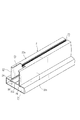
図1は、この発明に係るクリーンルームの天井構造の第1実施形態を示す断面図、図2は、天井構造の要部を示す拡大断面図、図3は、天井構造の要部を示す斜視図、図4は、この発明における継手部材の固定状態を示す一部断面斜視図、図5(a)は、図1のI−I線に沿う断面図、図5(b)は、図1のII−II線に沿う断面図である。
<First Embodiment>
1 is a cross-sectional view showing a first embodiment of a ceiling structure of a clean room according to the present invention, FIG. 2 is an enlarged cross-sectional view showing the main part of the ceiling structure, and FIG. 3 is a perspective view showing the main part of the ceiling structure. 4 is a partial cross-sectional perspective view showing a fixed state of the joint member in the present invention, FIG. 5A is a cross-sectional view taken along the line I-I in FIG. 1, and FIG. It is sectional drawing which follows the II-II line.
上記天井構造は、図1及び図2に示すように、天井を構成する位置に格子状に配置されると共に、継手部材30及び押え部材40を介して接合される主天井レール1及び補助天井レール2と、これら天井レール1,2によって区画された四角形状の格子状空間(図示せず)を、天井レール1,2の上側から塞ぐ天井板3と、この天井板3以外の格子状空間内に配置されるファンフィルタユニット(FFU)4とを備えている。
As shown in FIGS. 1 and 2, the ceiling structure is arranged in a lattice shape at positions constituting the ceiling, and is joined via a
上記主天井レール1は、図1ないし図3に示すように、仕切壁11によって上下に区画される上部空間12と下部空間13を有する中空状の垂直基部10と、この垂直基部10の下端両側に延在され、天井板3あるいはFFU4を載置可能な一対の中空状の外向きフランジ部14(以下に中空フランジ部14という)と、垂直基部10の上部片10aの上部に延在する上部狭隘開口溝15と、垂直基部10の下部片10bと両中空フランジ部14の側部片14b及び該側部片14bの下端部から相対向する方向に延在する水平片14cとからなる下部狭隘開口溝16を具備してなる。なお、上記垂直基部10は、必ずしも中空状である必要はなく、中実状に形成したものであってもよい。
As shown in FIGS. 1 to 3, the
この場合、中空フランジ部14は、上部片14aと、一対の側部片14bと、下部片14cとからなる中空部14dを具備しており、上部片14aの上面の基端側部位に、上方が開口すると共に、先端側に向かって拡開する勾配面17を有する第1の嵌入溝18が主天井レール1に沿って形成されている。
In this case, the
また、垂直基部における第1の嵌入溝18の上方に下方が開口する円弧状の凹状曲面19aを有する係合溝19が主天井レール1に沿って形成されている。
Further, an
また、主天井レール1の垂直基部10において、第1の嵌入溝18と係合溝19との間には、上方が開口すると共に、先端側に向かって拡開する勾配面17aを有する第2の嵌入溝18aが主天井レール1に沿って形成されている。
Further, in the
このように構成される主天井レール1は、アルミニウム製押出形材にて形成されている。また、下部狭隘開口溝16の開口部には、合成樹脂製のキャップ部材5が着脱可能に装着されるようになっている。
The
補助天井レール2は、図1ないし図6に示すように、仕切壁20によって区画される中空フランジ部14と同じ高さを有する略扁平矩形状の下部中空部21と、この下部中空部21の中央部の上方に起立する矩形状の上部中空部22とを具備してなる。なお、仕切壁20の下面中央部には、ねじの結合を強固にするために肉厚部20aが形成されている。また、上部中空部22の上部片22aの中央にはねじ溝23が補助天井レール2に沿って形成されている。また、上部中空部22における仕切壁20の上方近傍部位の対峙する側壁22bの対向面には、一対の案内凸条24が設けられている。この案内凸条24と仕切壁20との間に、後述する継手部材30の水平片32が挿入可能になっている。
As shown in FIGS. 1 to 6, the
なお、補助天井レール2の主天井レール1との接合側端部において、上部片22aに切欠き25が設けられている(図1及び図6参照)。このように切欠き25を設ける理由は、後述する継手部材30を固定するための下部固定部材である下部固定ねじ50a〜50cを操作する工具例えばドライバの操作を容易にするためである。
In addition, the
このように構成される補助天井レール2は、上記主天井レール1と同様にアルミニウム製押出形材にて形成されている。
The
一方、上記継手部材30は、図1ないし図3,図5及び図7に示すように、主天井レール1の垂直基部10の側部片10cに当接する垂直片31と、上記中空フランジ部14の上部片14a及び補助天井レール2の仕切壁20上に載置されるように掛け渡される水平片32とを有するアングル状に形成されている。
On the other hand, as shown in FIGS. 1 to 3, 5, and 7, the
この場合、継手部材30の一端部すなわち垂直片31の下面には、第1の嵌入溝18に摺動可能に嵌合すべく下方に向かって狭小となる勾配面33を有する第1の嵌入凸条34が形成されている。また、垂直片31の上部には、第2の嵌入溝18aに摺動可能に嵌合すべく下方に向かって狭小となる勾配面33aを有する第2の嵌入凸条34aが形成されている。更に、継手部材30の一端部の上面すなわち第2の嵌入凸条34aの上面には押え部材40と接触する当接面35が形成されている。
In this case, a first fitting protrusion having a
また、継手部材30の水平片32における垂直片31側の部位には、補助天井レール2の端面と係合する係止段部36が設けられている。更に、継手部材30の水平片32には、継手部材30と主天井レール1及び補助天井レール2とを固定する3個の下部固定部材例えば第1〜第3の下部固定ねじ50a,50b,50cの取付孔37a,37b,37cが穿設されている。この場合、水平片32における係止段部36より先端側に2個の取付孔37a,37bが穿設され、係止段部36より基端側に1個の取付孔37cが穿設されている(図7参照)。なお、継手部材30の水平片32における取付孔37cが穿設され位置には位置決め用の細溝38が形成されている。
Further, a locking
上記のように構成される継手部材30は、アルミニウム製押出形材を所定寸法に切断したピース状部材にて形成されている。
The
また、上記押え部材40は、図1,図2,図3,図5(a)及び図8に示すように、補助天井レール2の上部片22aの上面に当接する平坦状の押圧片41と、この押圧片41の一端部すなわち主天井レール1側端部から直角に折曲されて主天井レール1の垂直基部10の側面に当接する垂下片42とを有するアングル状に形成されている。
The pressing
この場合、垂下片42の上端部には、主天井レール1に設けられた係合溝19に係合する円弧状の凸状曲面43aを有する係合凸条43が形成されている。また、垂下片42の下端部には、継手部材30の当接面35と接触する凸状円弧状の当接凸条44が形成されている。
In this case, an engaging
なお、押圧片41の先端側部位には、2個の上部固定部材例えば第1,第2の上部固定ねじ51a,51bが貫通可能な長孔状の取付孔45a,45bが穿設されている。なお、押圧片41における取付孔45a,45bが穿設され位置には位置決め用の細溝46が形成されている。
In addition,
上記のように構成される押え部材40は、アルミニウム製押出形材を所定寸法に切断したピース状部材にて形成されている。
The pressing
次に、上記主天井レール1と補助天井レール2の接合手順について説明する。まず、工場等において、継手部材30の水平片32を補助天井レール2の上部中空部22内の仕切壁20と案内凸条24との間に挿入すると共に、仕切壁20上に載置し、係止段部36を補助天井レール2の端面に係合させる。そして、取付孔37a,37b内に第1及び第2の下部固定ねじ50a,50bを貫通して水平片32を仕切壁20の肉厚部20aにねじ結合して固定する。
Next, a procedure for joining the
次に、現場において、吊りボルト(図示せず)を介して建物の躯体(図示せず)側に主天井レール1を所定の間隔をおいて平行に配置する。次いで、継手部材30を固定した補助天井レール2を2本の主天井レール1間に挿入し、継手部材30の垂直片31を主天井レール1の垂直基部10の側面に当接させると共に、継手部材30の第1及び第2の嵌入凸条34,34aの勾配面33,33aを、主天井レール1の中空フランジ部14に設けられた第1及び第2の嵌入溝18,18aの勾配面17,17aに嵌合して、継手部材30の水平片32を中空フランジ部14の上部片14aの上面に当接するように掛け渡す。そして、継手部材30に穿設された取付孔37c内に第3の下部固定ねじ50cを貫通して中空フランジ部14の上部片14aにねじ結合して、継手部材30を主天井レール1に固定する。この際、第3の下部固定ねじ50cのねじ込みに伴って第1及び第2の嵌入溝18,18aの勾配面17,17aと第1及び第2の嵌入凸条34,34aの勾配面33,33aが互いに摺動しつつ係合するので、主天井レール1に対して補助天井レール2が引き寄せられる。したがって、主天井レール1と補助天井レール2とを簡単に隙間なく接合することができ、天井面を均一にすることができる。
Next, on the site, the main ceiling rails 1 are arranged in parallel at predetermined intervals on the building (not shown) side of the building via suspension bolts (not shown). Next, the
なお、この場合、第1及び第2の下部固定ねじ50a,50bは仕切壁20を貫通するが、その突出部は下部中空部21内に納められ、また、第3の下部固定ねじ50cは、中空フランジ部14の上部片14aを貫通するが、その突出部は中空フランジ部14の中空部14d内に納められるので、外部すなわちクリーンルーム内に露出することはない。したがって、天井部の美観の向上が図れる。
In this case, the first and second
上記のようにして継手部材30を介して主天井レール1と補助天井レール2を固定した後、図1及び図2に想像線で示すように、押え部材40の凸状曲面43aを有する係合凸条43を主天井レール1に設けられた凹状曲面19aを有する係合溝19内に係合させた状態で、押え部材40を図において時計方向に回動して当接凸条44を継手部材30の当接面35に当接すると共に、押圧片41を補助天井レール2の上部片22aの上面に当接する。この際、係合溝19の凹状曲面19aと係合凸条43の凸状曲面43aが回動自在に係合し、かつ、当接凸条44が凸状曲面を有するので、押え部材40の取り付けを容易に行うことができる。このようにして、押え部材40の押圧片41を補助天井レール2の上部片22aの上面に当接した状態で、押え部材40に穿設された取付孔45a,45bを貫通する第1及び第2の上部固定ねじ51a,51bを補助天井レール2に設けられたねじ溝23にねじ結合して、主天井レール1と補助天井レール2とを接合する。これにより、主天井レール1と補助天井レール2の接合を強固にすることができると共に、堅牢な天井構造とすることができる。
After the
上記のようにして主天井レール1と補助天井レール2を接合して格子状空間を形成し、各格子状空間にFFU4あるいは天井板3を載置して天井部を構成する。この際、補助天井レール2に設けられたねじ溝23を利用してFFU4を固定することができる。
As described above, the
上記のように構成されるこの発明に係る天井構造によれば、主天井レール1と補助天井レール2とを、継手部材30と押え部材40の複数の部材をそれぞれ固定して接合することができるので、主天井レール1と補助天井レール2の接合を強固にすることができる。また、主天井レール1に係合し、補助天井レール2に固定される押え部材40によって継手部材30の浮上りを阻止することができるので、地震等による引張・曲げ及び捩り加重による継手部材30の浮上りやそれに伴う補助天井レール2の捩れ・脱落を起こすことのない、堅牢な天井構造とすることができる。
According to the ceiling structure according to the present invention configured as described above, the
<第2実施形態>
図9は、この発明に係る天井構造の第2実施形態を示す断面図、図10は、第2実施形態の天井構造の要部を示す斜視図、図11は、第2実施形態の天井構造の要部を示す分解斜視図である。
Second Embodiment
FIG. 9 is a sectional view showing a second embodiment of a ceiling structure according to the present invention, FIG. 10 is a perspective view showing the main part of the ceiling structure of the second embodiment, and FIG. 11 is a ceiling structure of the second embodiment. It is a disassembled perspective view which shows the principal part.
第2実施形態は、第1実施形態に比べて高さ寸法の低い主天井レール1A及び補助天井レール2Aを用いて格子状部を形成し、第1実施形態の押え部材40と形態の異なる押え部材40Aを用いて主天井レール1Aと補助天井レール2Aを接合するようにした場合である。
In the second embodiment, a grid-like portion is formed using the
第2実施形態における主天井レール1Aは、図9ないし図11に示すように、中空矩形状の垂直基部10Aと、この垂直基部10Aの下端両側に延在され、天井板3あるいはFFU5を載置可能な一対の中空状の外向きフランジ部14(中空フランジ部14)と、垂直基部10Aの上部片10aの上部に延在する上部狭隘開口溝15と、垂直基部10の下部片10bと両中空フランジ部14の側部片14b及び該側部片14bの下端部から相対向する方向に延在する水平片14cとからなる下部狭隘開口溝16を具備してなる。なお、垂直基部10Aは、必ずしも中空状である必要はなく、中実状に形成したものであってもよい。
As shown in FIGS. 9 to 11, the
主天井レール1Aのその他の部分は第1実施形態と同様に形成されている。すなわち、中空フランジ部14の上部片14aの上面の基端側部位に、上方が開口すると共に、先端側に向かって拡開する勾配面17を有する第1の嵌入溝18が主天井レール1Aに沿って形成されている。また、垂直基部10Aにおける第1の嵌入溝18の上方に下方が開口する円弧状の凹状曲面19aを有する係合溝19が主天井レール1Aに沿って形成されている。更にまた、主天井レール1Aの垂直基部10Aにおいて、第1の嵌入溝18と係合溝19との間には、上方が開口すると共に、先端側に向かって拡開する勾配面17aを有する第2の嵌入溝18aが主天井レール1Aに沿って形成されている。
Other portions of the
このように構成される主天井レール1は、アルミニウム製押出形材にて形成されている。また、下部狭隘開口溝16の開口部には、合成樹脂製のキャップ部材5が着脱可能に装着されるようになっている。
The
補助天井レール2Aは、第1実施形態における補助天井レール2の上部中空部22Aの高さ寸法を低くした点以外は第1実施形態と同様に形成されている。すなわち、仕切壁20によって区画される中空フランジ部14と同じ高さを有する略扁平矩形状の下部中空部21と、この下部中空部21の中央部の上方に起立する矩形状の上部中空部22Aとを具備してなる。また、上部中空部22Aの上部片22aの中央にはねじ溝23が補助天井レール2に沿って形成されている。また、上部中空部22Aにおける仕切壁20の上方近傍部位の対峙する側壁22bの対向面には、一対の案内凸条24が設けられている。この案内凸条24と仕切壁20との間に、継手部材30の水平片32が挿入可能になっている。なお、補助天井レール2Aの主天井レール1Aとの接合側端部において、第1実施形態と同様に、上部片22aに切欠き25が設けられている(図11参照)。
The
このように構成される補助天井レール2Aは、上記主天井レール1Aと同様にアルミニウム製押出形材にて形成されている。
The
一方、押え部材40Aは、図9ないし図12に示すように、補助天井レール2Aの上部片22aの上面に当接する平坦状の押圧片41Aと、この押圧片41Aの一端部すなわち主天井レール1側端部から登り勾配状に延在する傾斜片47と、この傾斜片47の先端部から押圧片41Aに対して直角に折曲されて主天井レール1の垂直基部10の側面に当接する垂下片42とを有する形状に形成されている。
On the other hand, as shown in FIGS. 9 to 12, the pressing
押え部材40Aのその他の部分は第1実施形態と同様に形成されている。すなわち、垂下片42の上端部には、主天井レール1に設けられた係合溝19に係合する円弧状の凸状曲面43aを有する係合凸条43が形成されている。また、垂下片42の下端部には、継手部材30の当接面35と接触する凸状円弧状の当接凸条44形成されている。
Other portions of the
上記のように構成される押え部材40は、アルミニウム製押出形材を所定寸法に切断したピース状部材にて形成されている。
The pressing
なお、第2実施形態において、その他の部分は第1実施形態と同じであるので、同一部分には同一符号を付して説明は省略する。 In the second embodiment, the other parts are the same as those in the first embodiment, so the same parts are denoted by the same reference numerals and description thereof is omitted.
上記主天井レール1Aと補助天井レール2Aとを接合する手順は第1実施形態と同様にして行うことができる。すなわち、まず、工場等において、継手部材30の水平片32を補助天井レール2Aの上部中空部22A内の仕切壁20と案内凸条24との間に挿入すると共に、仕切壁20上に載置し、係止段部36を補助天井レール2の端面に係合させる。そして、取付孔37a,37b内に第1及び第2の下部固定ねじ50a,50bを貫通して水平片32を仕切壁20の肉厚部20aにねじ結合して固定する。
The procedure for joining the
次に、現場において、吊りボルト(図示せず)を介して建物の躯体(図示せず)側に主天井レール1Aを所定の間隔をおいて平行に配置する。次いで、継手部材30を固定した補助天井レール2Aを2本の主天井レール1A間に挿入し、継手部材30の垂直片31を主天井レール1Aの垂直基部10Aの側面に当接させると共に、継手部材30の第1及び第2の嵌入凸条34,34aの勾配面33,33aを、主天井レール1Aの中空フランジ部14に設けられた第1及び第2の嵌入溝18,18aの勾配面17,17aに嵌合して、継手部材30の水平片32を中空フランジ部14の上部片14aの上面に当接するように掛け渡す。そして、継手部材30に穿設された取付孔37c内に第3の下部固定ねじ50cを貫通して中空フランジ部14の上部片14aにねじ結合して、継手部材30を主天井レール1に固定する。この際、第3の下部固定ねじ50cのねじ込みに伴って第1及び第2の嵌入溝18,18aの勾配面17,17aと第1及び第2の嵌入凸条34,34aの勾配面33,33aが互いに摺動しつつ係合して、主天井レール1Aに対して補助天井レール2Aが引き寄せられるので、主天井レール1Aと補助天井レール2Aとを簡単に隙間なく接合することができ、天井面を均一にすることができる。
Next, on the site, the
上記のようにして継手部材30を介して主天井レール1Aと補助天井レール2Aを固定した後、図9に想像線で示すように、押え部材40Aの凸状曲面43aを有する係合凸条43を主天井レール1Aに設けられた凹状曲面19aを有する係合溝19内に係合させた状態で、押え部材40Aを図において時計方向に回動して当接凸条44を継手部材30の当接面35に当接すると共に、押圧片41Aを補助天井レール2Aの上部片22aの上面に当接する。この際、係合溝19の凹状曲面19aと係合凸条43の凸状曲面43aが回動自在に係合し、かつ、当接凸条44が凸状曲面を有するので、押え部材40Aの取り付けを容易に行うことができる。このようにして、押え部材40Aの押圧片41Aを補助天井レール2Aの上部片22aの上面に当接した状態で、押え部材40Aに穿設された取付孔45a,45bを貫通する第1及び第2の上部固定ねじ51a,51bを補助天井レール2Aに設けられたねじ溝23にねじ結合して、主天井レール1Aと補助天井レール2Aとを接合する。これにより、主天井レール1Aと補助天井レール2Aの接合を強固にすることができると共に、堅牢な天井構造とすることができる。
After fixing the
上記のようにして主天井レール1Aと補助天井レール2Aを接合して格子状空間を形成し、各格子状空間にFFU4あるいは天井板3を載置して天井部を構成する。
As described above, the
なお、第2実施形態では、第1実施形態の主天井レール1に対して高さ寸法の低い主天井レール1Aを用いているが、第1及び第2の嵌入溝18,18aに対する係合溝19の距離(寸法)は同じである。したがって、第2実施形態において、主天井レール1Aに代えて第1実施形態の主天井レール1を用いてもよい。
In addition, in 2nd Embodiment, although the
上記のように構成される第2実施形態の天井構造によれば、第1実施形態と同様の効果が得られる他に、押え部材40Aを代えることで、配置する低い高さ寸法の補助天井レール2Aを主天井レール1Aに接合することができる。また、図9に想像線で示すように、押え部材40Aに代えて第1実施形態の押え部材40を用いることで、高さ寸法の高い補助天井レール2を接合することができる。このように、形状の異なる押え部材40,40Aを選択して用いることで、配置する補助天井レール2,2Aの高さの自由度を保たせることができる。更にまた、主天井レール1,1Aに係合し、補助天井レール2Aに固定される押え部材40Aによって継手部材30の浮上りを阻止することができるので、地震等による引張・曲げ及び捩り加重による継手部材30の浮上りやそれに伴う補助天井レール2の捩れ・脱落を起こすことのない、堅牢な天井構造とすることができる。
According to the ceiling structure of the second embodiment configured as described above, the same effect as that of the first embodiment can be obtained, and the auxiliary ceiling rail having a low height dimension can be arranged by replacing the
<その他の実施形態>
なお、上記実施形態では、主天井レール1,1Aに設けられた第1及び第2の嵌入溝18,18aに、継手部材30に設けられた第1及び第2の嵌入凸条34,34aを嵌合させた状態で、下部固定ねじ50a〜50cによって固定する場合について説明したが、強度が許される場合には、第1の嵌入溝18と第1の嵌入凸条34の嵌合を省略してもよい。この場合においても、継手部材30は押え部材40,40Aによって押圧されて固定されているので、地震等による引張・曲げ及び捩り加重による継手部材30の浮上りやそれに伴う補助天井レール2,2Aの捩れ・脱落を起こすことのない、堅牢な天井構造とすることができる。
<Other embodiments>
In the above embodiment, the first and
なお、上記実施形態ではクリーンルームの天井構造について説明したが、クリーンルーム以外においても、天井板3やFFU4(フィルタユニット)等の天井設備を載置すべく格子状に配置される天井レールを具備するものであれば、その他のシステム天井の天井構造にも適用することができる。 In addition, although the said embodiment demonstrated the ceiling structure of the clean room, what is equipped with the ceiling rail arrange | positioned in a grid | lattice form in order to mount ceiling equipment, such as the ceiling board 3 and FFU4 (filter unit), also in places other than a clean room. If so, the present invention can be applied to the ceiling structure of other system ceilings.
1,1A 主天井レール
2,2A 補助天井レール
3 天井板
4 FFU(ファンフィルタユニット)
10,10A 垂直基部
14 外向きフランジ部(中空フランジ部)
17,17a 勾配面
18 第1の嵌入溝
18a 第2の嵌入溝
19 係合溝
19a 凹状曲面
23 ねじ溝
30 継手部材
33,33a 勾配面
34 第1の嵌入凸条
34a 第2の嵌入凸条
35 当接面
37a,37b,37c 取付孔
40,40A 押え部材
41,41A 押圧片
43 係合凸条
43a 凸状曲面
44 当接凸条
45a,45b 取付孔
50a,50b,50c 下部固定ねじ(固定部材)
51a,51b 上部固定ねじ(固定部材)
1,1A
10, 10A Vertical base 14 Outward flange (hollow flange)
17,
51a, 51b Upper fixing screw (fixing member)
Claims (6)
上記主天井レールの垂直基部の下端部に外向きフランジ部を形成すると共に、外向きフランジ部の上面の基端側部位に、上方が開口する嵌入溝を主天井レールに沿って形成し、上記垂直基部における上記嵌入溝の上方に下方が開口する係合溝を主天井レールに沿って形成し、
上記継手部材の一端部に、上記嵌入溝に嵌合する嵌入凸条及び上記押え部材と接触する当接面を形成し、
上記押え部材の一端部に、上記係合溝に係合する係合凸条及び上記継手部材と接触する当接凸条を形成し、
上記嵌入溝に上記嵌入凸条を嵌合させた状態で、上記継手部材を上記外向きフランジ部と上記補助天井レールの端部に掛け渡すと共に、外向きフランジ部及び補助天井レールに下部固定部材をもって固定し、上記係合溝に上記係合凸条を係合させると共に、上記当接凸条を上記当接面に当接させた状態で、押え部材を上記補助天井レールの端部に上部固定部材をもって固定して、主天井レールと補助天井レールを接合する、ことを特徴とするクリーンルーム等の天井構造。 A ceiling structure such as a clean room in which main ceiling rails and auxiliary ceiling rails arranged in a lattice shape to place ceiling equipment such as a ceiling plate and a filter unit are joined via a joint member and a holding member,
Forming an outward flange portion at a lower end portion of the vertical base portion of the main ceiling rail, and forming an insertion groove along the main ceiling rail, with an opening opening on the proximal end portion of the upper surface of the outward flange portion; Forming an engagement groove along the main ceiling rail that opens downward above the insertion groove in the vertical base;
At one end portion of the joint member, an insertion protrusion that fits into the insertion groove and an abutting surface that contacts the pressing member are formed,
On one end portion of the presser member, an engagement protrusion that engages with the engagement groove and a contact protrusion that contacts the joint member are formed.
In a state where the fitting protrusion is fitted in the fitting groove, the joint member is stretched over the outward flange portion and the end of the auxiliary ceiling rail, and the lower fixing member is attached to the outward flange portion and the auxiliary ceiling rail. In the state where the engaging ridge is engaged with the engaging groove and the abutting ridge is brought into contact with the abutting surface, the presser member is placed on the end of the auxiliary ceiling rail. A ceiling structure for a clean room or the like, characterized in that the main ceiling rail and the auxiliary ceiling rail are joined together with a fixing member.
上記主天井レールの外向きフランジ部は、上部片、側部片及び下部片からなる中空部を有し、
上記補助天井レールは、仕切壁によって区画される上部及び下部中空部を有し、
上記継手部材と外向きフランジ部及び補助天井レールとを固定すべく上記上部片及び仕切壁を貫通する上記下部固定部材の突出部を上記中空部内及び下部中空部内に納めると共に、上記押え部材と補助天井レールとを固定すべく補助天井レールの上部を貫通する上記上部固定部材の突出部を上記上部中空部内に納めるようにした、ことを特徴とするクリーンルーム等の天井構造。 In the ceiling structure of the clean room or the like according to claim 1,
The outward flange portion of the main ceiling rail has a hollow portion composed of an upper piece, a side piece, and a lower piece,
The auxiliary ceiling rail has an upper part and a lower hollow part defined by a partition wall,
In order to fix the joint member, the outward flange portion and the auxiliary ceiling rail, the protruding portion of the lower fixing member penetrating the upper piece and the partition wall is accommodated in the hollow portion and the lower hollow portion, and the holding member and the auxiliary member are supported. A ceiling structure for a clean room or the like, characterized in that a protruding portion of the upper fixing member that penetrates the upper portion of the auxiliary ceiling rail to be fixed to the ceiling rail is accommodated in the upper hollow portion.
上記主天井レールの垂直基部において、上記嵌入溝と上記係合溝との間に、上方が開口する第2の嵌入溝を主天井レールに沿って形成し、
上記継手部材の一端部に、上記第2の嵌入溝に嵌合する第2の嵌入凸条を形成する、ことを特徴とするクリーンルーム等の天井構造。 In the ceiling structure such as the clean room according to claim 1 or 2,
In the vertical base of the main ceiling rail, a second insertion groove that opens upward is formed along the main ceiling rail between the insertion groove and the engagement groove.
A ceiling structure for a clean room or the like, wherein a second insertion protrusion that fits into the second insertion groove is formed at one end of the joint member.
上記嵌入溝は先端側に向かって拡開する勾配面を有すると共に、上記嵌入凸条は上記嵌入溝に嵌合すべく下方に向かって狭小となる勾配面を有する、ことを特徴とするクリーンルーム等の天井構造。 In the ceiling structure such as the clean room according to any one of claims 1 to 3,
The insertion groove has a slope surface that expands toward the tip side, and the insertion protrusion has a slope surface that narrows downward so as to fit in the insertion groove. Ceiling structure.
上記係合溝は円弧状の凹状曲面を有すると共に、上記係合凸条は上記係合溝に回動可能に係合するように円弧状の凸状曲面を有する、ことを特徴とするクリーンルーム等の天井構造。 In the ceiling structure such as a clean room according to any one of claims 1 to 4,
The engaging groove has an arcuate concave curved surface, and the engaging ridge has an arcuate convex curved surface so as to be pivotably engaged with the engaging groove. Ceiling structure.
上記補助天井レールの上面には、この補助天井レールに沿うねじ溝が設けられている、ことを特徴とするクリーンルーム等の天井構造。 In the ceiling structure such as the clean room according to any one of claims 1 to 5,
A ceiling structure for a clean room or the like, characterized in that a screw groove along the auxiliary ceiling rail is provided on the upper surface of the auxiliary ceiling rail.
Priority Applications (1)
| Application Number | Priority Date | Filing Date | Title |
|---|---|---|---|
| JP2006255747A JP4841374B2 (en) | 2006-09-21 | 2006-09-21 | Ceiling structure for clean rooms, etc. |
Applications Claiming Priority (1)
| Application Number | Priority Date | Filing Date | Title |
|---|---|---|---|
| JP2006255747A JP4841374B2 (en) | 2006-09-21 | 2006-09-21 | Ceiling structure for clean rooms, etc. |
Publications (2)
| Publication Number | Publication Date |
|---|---|
| JP2008075337A JP2008075337A (en) | 2008-04-03 |
| JP4841374B2 true JP4841374B2 (en) | 2011-12-21 |
Family
ID=39347685
Family Applications (1)
| Application Number | Title | Priority Date | Filing Date |
|---|---|---|---|
| JP2006255747A Active JP4841374B2 (en) | 2006-09-21 | 2006-09-21 | Ceiling structure for clean rooms, etc. |
Country Status (1)
| Country | Link |
|---|---|
| JP (1) | JP4841374B2 (en) |
Families Citing this family (1)
| Publication number | Priority date | Publication date | Assignee | Title |
|---|---|---|---|---|
| JP7233818B2 (en) * | 2019-07-22 | 2023-03-07 | 日軽パネルシステム株式会社 | Connection structure of beams in suspended ceiling and connection method thereof |
Family Cites Families (1)
| Publication number | Priority date | Publication date | Assignee | Title |
|---|---|---|---|---|
| JP3271543B2 (en) * | 1997-02-18 | 2002-04-02 | 日本軽金属株式会社 | System ceiling |
-
2006
- 2006-09-21 JP JP2006255747A patent/JP4841374B2/en active Active
Also Published As
| Publication number | Publication date |
|---|---|
| JP2008075337A (en) | 2008-04-03 |
Similar Documents
| Publication | Publication Date | Title |
|---|---|---|
| US9187896B1 (en) | Assembly for supporting ceiling panels and ceiling system incorporating the same | |
| US9435121B2 (en) | Assembly for supporting ceiling panels and ceiling system incorporating the same | |
| US9181696B1 (en) | Assembly for supporting ceiling panels and ceiling system incorporating the same | |
| KR20080027719A (en) | Structure for fixing the ceiling plate | |
| US7634881B2 (en) | Cross panel | |
| KR200455273Y1 (en) | Fixing structure of ceiling panel | |
| JP5439003B2 (en) | Securing clip | |
| JP4841374B2 (en) | Ceiling structure for clean rooms, etc. | |
| KR102084704B1 (en) | A fixing structure of ceiling panels | |
| JP6778090B2 (en) | Hanger and system ceiling structure using the hanger | |
| JP2010106612A (en) | Joint structure of flat column and beam | |
| JP2019052737A (en) | Pipe joint | |
| JP6468809B2 (en) | Membrane ceiling structure and its construction method | |
| JP3079453B2 (en) | Connection fitting for ceiling bar | |
| JP2011256677A (en) | Ceiling-mounted fire extinction system | |
| JP6263759B2 (en) | Deck material fixing structure | |
| JP2005256397A (en) | Wall panel and its fitting method | |
| JP7233818B2 (en) | Connection structure of beams in suspended ceiling and connection method thereof | |
| JP7421675B1 (en) | Louver material and system ceiling | |
| JP2018071338A (en) | Ceiling structure, ceiling board installation component and construction method of ceiling structure | |
| KR102532942B1 (en) | Finishing material for a ceiling of building | |
| JP7276834B2 (en) | Ceiling plate fall prevention device and ceiling structure | |
| JP6205178B2 (en) | Connecting mechanism for suspension plate for ceiling board | |
| CN213204587U (en) | Buckle body, wallboard and integral bathroom | |
| JP2000336810A (en) | Fitting jig of long sub-component to main component for building |
Legal Events
| Date | Code | Title | Description |
|---|---|---|---|
| A625 | Written request for application examination (by other person) |
Free format text: JAPANESE INTERMEDIATE CODE: A625 Effective date: 20090119 |
|
| TRDD | Decision of grant or rejection written | ||
| A01 | Written decision to grant a patent or to grant a registration (utility model) |
Free format text: JAPANESE INTERMEDIATE CODE: A01 Effective date: 20111004 |
|
| A01 | Written decision to grant a patent or to grant a registration (utility model) |
Free format text: JAPANESE INTERMEDIATE CODE: A01 |
|
| A61 | First payment of annual fees (during grant procedure) |
Free format text: JAPANESE INTERMEDIATE CODE: A61 Effective date: 20111004 |
|
| R150 | Certificate of patent or registration of utility model |
Ref document number: 4841374 Country of ref document: JP Free format text: JAPANESE INTERMEDIATE CODE: R150 Free format text: JAPANESE INTERMEDIATE CODE: R150 |
|
| FPAY | Renewal fee payment (event date is renewal date of database) |
Free format text: PAYMENT UNTIL: 20141014 Year of fee payment: 3 |
|
| S531 | Written request for registration of change of domicile |
Free format text: JAPANESE INTERMEDIATE CODE: R313531 |
|
| R350 | Written notification of registration of transfer |
Free format text: JAPANESE INTERMEDIATE CODE: R350 |