JP4840737B2 - Waste treatment method, lump-molded product obtained by the waste treatment method, and waste treatment system - Google Patents
Waste treatment method, lump-molded product obtained by the waste treatment method, and waste treatment system Download PDFInfo
- Publication number
- JP4840737B2 JP4840737B2 JP2001178244A JP2001178244A JP4840737B2 JP 4840737 B2 JP4840737 B2 JP 4840737B2 JP 2001178244 A JP2001178244 A JP 2001178244A JP 2001178244 A JP2001178244 A JP 2001178244A JP 4840737 B2 JP4840737 B2 JP 4840737B2
- Authority
- JP
- Japan
- Prior art keywords
- waste
- molded product
- plastic
- melt
- hazardous
- Prior art date
- Legal status (The legal status is an assumption and is not a legal conclusion. Google has not performed a legal analysis and makes no representation as to the accuracy of the status listed.)
- Expired - Lifetime
Links
Images


Classifications
-
- Y—GENERAL TAGGING OF NEW TECHNOLOGICAL DEVELOPMENTS; GENERAL TAGGING OF CROSS-SECTIONAL TECHNOLOGIES SPANNING OVER SEVERAL SECTIONS OF THE IPC; TECHNICAL SUBJECTS COVERED BY FORMER USPC CROSS-REFERENCE ART COLLECTIONS [XRACs] AND DIGESTS
- Y02—TECHNOLOGIES OR APPLICATIONS FOR MITIGATION OR ADAPTATION AGAINST CLIMATE CHANGE
- Y02E—REDUCTION OF GREENHOUSE GAS [GHG] EMISSIONS, RELATED TO ENERGY GENERATION, TRANSMISSION OR DISTRIBUTION
- Y02E50/00—Technologies for the production of fuel of non-fossil origin
- Y02E50/10—Biofuels, e.g. bio-diesel
-
- Y—GENERAL TAGGING OF NEW TECHNOLOGICAL DEVELOPMENTS; GENERAL TAGGING OF CROSS-SECTIONAL TECHNOLOGIES SPANNING OVER SEVERAL SECTIONS OF THE IPC; TECHNICAL SUBJECTS COVERED BY FORMER USPC CROSS-REFERENCE ART COLLECTIONS [XRACs] AND DIGESTS
- Y02—TECHNOLOGIES OR APPLICATIONS FOR MITIGATION OR ADAPTATION AGAINST CLIMATE CHANGE
- Y02E—REDUCTION OF GREENHOUSE GAS [GHG] EMISSIONS, RELATED TO ENERGY GENERATION, TRANSMISSION OR DISTRIBUTION
- Y02E50/00—Technologies for the production of fuel of non-fossil origin
- Y02E50/30—Fuel from waste, e.g. synthetic alcohol or diesel
-
- Y—GENERAL TAGGING OF NEW TECHNOLOGICAL DEVELOPMENTS; GENERAL TAGGING OF CROSS-SECTIONAL TECHNOLOGIES SPANNING OVER SEVERAL SECTIONS OF THE IPC; TECHNICAL SUBJECTS COVERED BY FORMER USPC CROSS-REFERENCE ART COLLECTIONS [XRACs] AND DIGESTS
- Y02—TECHNOLOGIES OR APPLICATIONS FOR MITIGATION OR ADAPTATION AGAINST CLIMATE CHANGE
- Y02W—CLIMATE CHANGE MITIGATION TECHNOLOGIES RELATED TO WASTEWATER TREATMENT OR WASTE MANAGEMENT
- Y02W10/00—Technologies for wastewater treatment
- Y02W10/30—Wastewater or sewage treatment systems using renewable energies
- Y02W10/37—Wastewater or sewage treatment systems using renewable energies using solar energy
-
- Y—GENERAL TAGGING OF NEW TECHNOLOGICAL DEVELOPMENTS; GENERAL TAGGING OF CROSS-SECTIONAL TECHNOLOGIES SPANNING OVER SEVERAL SECTIONS OF THE IPC; TECHNICAL SUBJECTS COVERED BY FORMER USPC CROSS-REFERENCE ART COLLECTIONS [XRACs] AND DIGESTS
- Y02—TECHNOLOGIES OR APPLICATIONS FOR MITIGATION OR ADAPTATION AGAINST CLIMATE CHANGE
- Y02W—CLIMATE CHANGE MITIGATION TECHNOLOGIES RELATED TO WASTEWATER TREATMENT OR WASTE MANAGEMENT
- Y02W30/00—Technologies for solid waste management
- Y02W30/50—Reuse, recycling or recovery technologies
- Y02W30/62—Plastics recycling; Rubber recycling
Description
【0001】
【発明の属する技術分野】
本発明は、一般廃棄物、産業廃棄物などの多種多様の廃棄物を地球環境に影響を及ぼすことを極小限に抑えつつ、極めて経済的、適切、安全に処理できる廃棄物の処理に関し、詳しくは、廃棄物処理方法、その廃棄物処理方法で得られた塊状成型物および廃棄物処理システムに関する。
【0002】
特に、焼却炉もしくは溶融炉などから排出される焼却灰、ばいじんなどの焼却廃棄物、汚泥、汚染土壌、スラッジなどの有害廃棄物を含む有害廃棄物を、一般家庭、工場などから排出されるプラスチック廃棄物を用いて塊状成型物を得、これを貯留する無公害処理に関するものである。
【0003】
また、行政区域内で発生する焼却廃棄物などとプラスチック廃棄物とを用いて塊状成型物を得、その塊状成型物を同一行政区域内の建設、土木工事事業における建設、土木工事資材として使用することで、また、溶融炉用の燃料として使用することで、焼却廃棄物およびプラスチック廃棄物の双方を再利用する行政区域内自己完結型を強力に志向し推進するための廃棄物処理に関するものである。
【0004】
また、金属成分を含有する廃棄物を、一般家庭や工場から排出されるプラスチック廃棄物を溶融させたものの中に混入せしめて塊状成形物とし、大量にかつ長期間にわたって安全に備蓄できるようにするとともに、備蓄した後、塊状成形物から含有される金属成分を分離回収する方法に関するものである。
【0005】
【従来の技術】
産業廃棄物もしくは一般廃棄物を焼却炉で焼却することで発生する焼却灰もしくはばいじんや溶融炉より発生するばいじんには、重金属やダイオキシンなどが含まれており、それらが自然環境中に飛散した場合にあってはとり返しのつかない環境汚染を引起こし長期にわたり、人体に重大な悪影響を及ぼすものとして問題になる。
【0006】
生活活動、事業活動に伴って排出される一般廃棄物、産業廃棄物などの廃棄物は多種多様であって、焼却やリサイクルが困難な廃棄物、焼却後の残渣あるいは焼却に伴って発生する有害廃棄物、ヘドロなどは、任意に放置すれば環境汚染などを引き起こすため、国の基準に基づき後述する安定型処分場、管理型処分場、遮断型処分場の何れかに半永久的に貯留されている。
【0007】
しかしながら、生活水準の向上、事業活動の活発化に伴い、排出される廃棄物の量は拡大の一途を辿っており、既存の処分場の残余年数が少なくなっている。このため、新たに処分場を建設する試みがなされているが、住民感情もあり、遅々として進まない状況にあり、処分場の不足が懸念されている。
【0008】
本発明は上記廃棄物を効果的に処理あるいは処分できる(総称して処理という)廃棄物の処理方法を提供するものであり、上記処分場不足を技術的に解決する廃棄物の処理方法を提供することを目的の1つとするものであるが、まず現在の廃棄物処理状況を次に説明する。
(1)廃棄物と処分場との関係について
図4は、廃棄物40と処分場52との関係を示す処理フローである。産業廃棄物もしくは一般家庭用廃棄物からなる廃棄物40は、その大半が焼却炉53で焼却処理もしくは溶融炉54で溶融処理される。廃棄物40は、焼却炉53で焼却処理された結果ばいじん44および焼却灰45を発生させることになる。また、廃棄物40は溶融炉54で溶融処理された結果ばいじん44を発生させることになる。このうち特に重金属含有濃度の高いばいじん44は、図4に示すようなセメント固化処理法A、薬剤処理法B、酸抽出処理法C、溶融処理法D、エコセメント処理法Eなどの中間処理にて重金属の安定化、固定化処理が成され、その後に処分場52にて最終処理されるのである。なお、焼却灰45についても、重金属の含有濃度が高いものについてはセメント固化処理法Aにて、重金属の安定化、固定化を行って処分場52に最終処分することが望ましい。
【0009】
一方、廃棄物40に含有されるプラスチック廃棄物41は、図4に示されるように、所定の形状に粉砕された後埋立処理59されるか、もしくは、焼却炉53で焼却処理されるかまたは溶融炉54で溶融処理される。または、リサイクル処理60される。特に、近年、容器包装のリサイクルが進み、一般家庭などから排出されるプラスチック廃棄物の回収が進み、プラスチック廃棄物の資源化・再利用化が比較的多く試みられている。
【0010】
廃棄物40はその種類に応じて上記各種中間処理をされた上、処分場52に貯留される。処分場52は大別して安定型処分場、管理型処分場、遮断型処分場の何れかに分類される。
【0011】
安定型処分場はガラス、瀬戸物、鉄、プラスチックなど化学的に安定した限られた廃棄物(5品目)しか貯留できず、その利用には限界がある。その中でも、プラスチック廃棄物41は所定の形状に粉砕した状態換言すればかさ張ったままの状態で廃棄されることが多く、安定型処分場の残余年数が急速になくなりつつあり、当該廃棄物の減量が望まれている。このため、プラスチック廃棄物41については、焼却も行なわれているが、多量に含まれている塩ビなどからダイオキシンが発生する恐れがあり、余り好ましくはなく徐々に減少しており、またプラスチック廃棄物を圧縮または熱を加えて軟化し容量を小さくして廃棄することも考えられるが、その分コスト的に高くなるため安定型処分場に廃棄する場合には、コスト的に不利となり、あまり採用されていないのが現状である。
【0012】
また、遮断型処分場は、有害廃棄物を含む廃棄物たとえばヘドロや燃え殻をそのままの状態で貯留しても、有害廃棄物が処分場外へ全く出ないように極めて厳重な封鎖構造としているもので、限られた場所に少数存在するだけであって、利用するにはコストが高く、通常の廃棄物には利用できない施設となっている。
【0013】
管理型処分場は、有害廃棄物が溶出あるいは流出しにくいように中間処理した廃棄物を貯留するものであって、焼却炉53などで焼却された結果得られたばいじん44、焼却灰45、および、熔融炉54にて生じるばいじん44などが、含有重金属の溶出を防止するセメント固化処理法Aなどの上記中間処理をされた上で貯留される。廃棄物40の大半はこの処理によって減容化が図られている。
【0014】
このような管理型処分場は、万が一有害廃棄物が流出あるいは溶出しても、周辺に環境汚染を起こさないように、貯留部分に遮水処理が施され、浸出水については、有害廃棄物を回収浄化する排水設備が付設されているもので、大掛かりな工事と建設費を必要とする上、住民感情を考慮して人里融れた場所に設置されているものである。しかも、後述するように貯留廃棄物から多量に溶出するカルシウム塩による排水設備のスケール化に対するメンテナンス費用、多種にわたる貯留廃棄物から経年変化後溶出する多種多様の有害廃棄物、BOD源、COD源の無害化、除去のために使用する多量の薬剤費用、設備費用、稼働費用などが高額となるので、維持管理費が極めて高くつくものである。
【0015】
このように、廃棄物40は現在既存の処分場52に貯留されているが、大量に発生する廃棄物40に対して、これら処分場52の不足が懸念されている。従って、新たな処分場を設けることが検討されているが、環境汚染を懸念する住民感情から、新設は極めて困難である。これは貯留物が様々な形態(粉、粒、瓦礫、汚泥形状など)で貯留されるので、環境汚染を引き起こす有害廃棄物だとの印象や飛散による汚染の恐れを与えるのもやむえない。
【0016】
一方、上述したように、焼却灰もしくはばいじんの最終処分場の新設が進まない現状と相俟って、ある地域内で発生する焼却灰、ばいじんを別地域にて処理される場合がある。たとえば、首都圏の焼却灰、ばいじんが南九州まで運ばれて処分されたり、埼玉県の焼却灰が福井県で処分されたりしている。多量の焼却灰、ばいじんをある地域から別地まで輸送するには多量の輸送エネルギーおよび人的資源を投入する必要性があり、しかも、焼却灰、ばいじんのような基本的に付加価値のないものに多量のエネルギーを消費することは解決すべき重要な問題である。
【0017】
従って、廃棄物の総量を減らすべく、ごみ自体を出さない生活の工夫や容器リサイクル法によるリサイクルの推進などが国単位、自治体単位で推進され、特にプラスチック廃棄物については、リサイクルの技術開発が積極的に行われているが、その技術が確立したとは言えず、廃棄物処分の切り札とはなっていない。
【0018】
たとえば、プラスチック廃棄物41を粉砕し、溶融させ、成型して再生品の用途を検討しているが、実用上品質、強度などの面で不足しており、殆ど実用化されていない。
【0019】
たとえば、プラスチック処理促進協会では、実験プラントを建設し、一般廃棄物として排出されるプラスチック廃棄物の再生が試みられた。このプラスチック廃棄物の再生は、プラスチック廃棄物を分別し、分別したプラスチック廃棄物を粉砕し、溶融させ、成型させる3工程からなるものであり、分別収集したプラスチック廃棄物を砂利状の小塊として処理するとともに、棒などの再生品を試作し、再生品の用途を検討するものであった。
【0020】
しかし、再生品はその内部構造が発泡質構造となり多孔質であるため、比較的比重の小さいものとなり、圧縮強度も小さく、さらに水に浮くので、地表面に出ない埋め立て以外には使用できなかった。また、型込成型を行なったとしても、溶融時のゲル化が不十分で金型への押込圧が低いことなどから、成型物内部に空隙を生じ、成型物の強度は不十分なものであった。
【0021】
このように、処分場52の不足に対して、現状においては廃棄物そのものの減量、あるいは廃棄物のリサイクル、処分場の新設を推進することにより対応しようとしているが、何れも行き詰まりの状況にある。
【0022】
つまり、これまで、処分場は廃棄物を廃棄する場所あるいは設備との観点からしか見られておらず、多種多様の廃棄物を単に投入し続けているだけで、処分場を有効に使うべく、廃棄物の貯留に技術的工夫を施すという考えが全くなかったのである。
【0023】
従って、既存の処分場をできるだけ有効に活用できる新親な廃棄物の処分方法が望まれている。
(2)中間処理方法の安全性について
図4において、廃棄物40はその大半が焼却炉53で焼却処理され、その結果、重金属やダイオキシンを含むばいじん44及び焼却灰45が生じ、個数の少ない溶融炉54で溶融処理によりばいじん54が生じる。このばいじん44は、含有される重金属を安定化・固定化するために、セメント固化処理法A、薬剤処理法B、酸抽出処理法C、溶融処理法D、エコセメント処理法Eなどの手法にて中間処理が行われている。なお、焼却灰45についても、有害廃棄物が所定の基準値以上の場合は、セメント固化により、有害廃棄物を固定化することが望ましい。
【0024】
しかしながら、上述したセメント固化処理法Aは、焼却灰45もしくはばいじん44をセメント中に混合して固化することで固化物を得る処理方法であるが、この手法で得られた固化物は雨水などに長期にわたって晒された場合はひび割れが発生し、内部に封入したばいじんなどの焼却廃棄物が一定期間経過後環境中に一気に流出する危険性がある。さらに、セメント固化処理法Aは、高濃度の重金属を含むばいじんの処理には不十分であるか不可能である。
【0025】
また、上述した薬剤処理法Bは、有機キレート剤や無機系粉体などの薬剤を使用して、焼却廃棄物中に含有される重金属類を安定化させる薬剤処理法があるが、この薬剤処理法Bは、ばいじん中のダイオキシン、カルシウム塩などの溶出抑制には不向きである。また、有機キレート剤は、酸性雨、土壌菌、紫外線劣化を起こす可能性があり、結果として環境汚染の原因になる場合がある。
【0026】
また、酸抽出処理法Cには、設備ランニングコストが比較的高価になる傾向にあるとともに、作業安全性に問題があり、その結果、酸抽出処理法Cを現実に採用している処理場は全国で2〜3ヶ所しかない。したがって、酸抽出処理法Cは現実的な実用性に問題がある。
【0027】
また、溶融処理法Dには、イニシャアルコストおよびランニングコストがともに比較的高価になる傾向があるため、全国的な導入に数十年の長期間を要するので、現実的な実用性に問題がある。
【0028】
また、エコセメント処理法Eは、ばいじんなどをセメント材料として使用する処理法であるが、エコセメント処理法で得られたセメントには塩素化合物が含有されており、使用用途が限定されるという問題がある。
【0029】
さらに、上述した固化処理法A、薬剤処理法B、酸抽出処理法Cは、特にダイオキシンやカルシウム化合物を安定化させる効果が不十分であるばかりでなく、処理された焼却廃棄物は最終処分場に埋め立てる必要があるため、前述の最終処分場の不足や浸出水処理上の問題は深刻で、焼却廃棄物の行き場がなくなるという事態を招くことになる可能性がある。
【0030】
また、上述した固化処理法A、薬剤処理法B、酸抽出処理法Cは、重金属の溶出を抑制することに主眼を置いたものであり、最近のように厳しいダイオキシン規制のもとでは、その安定化、固定化、場合によっては無害化処理が十分とは言えないものであった。さらに、溶融処理法D、エコセメント処理法Eは、ダイオキシンの分解、無害化に効果があり、有効利用される場合があるものの、設備やランニングコストが非常に高く、全国的な普及には時間がかかるため、即効性がない。
【0031】
それ故、これまで以上に安価に処理できかつダイオキシンの流出を効果的に防ぐ中間処理方法が求められていた。
【0032】
一方、これまで重金属や重金属酸化物などの金属成分を含有する焼却灰もしくはばいじんは、金属成分が環境中に漏洩し自然環境中に害をなす場合も考えられることから、金属成分の溶出を防止するために、上述したセメント固化法や薬剤処理法によって中間処理をした上、他の廃棄物とともに最終処理場に埋め立てされていた。しかしながら、これら焼却灰、ばいじん中に含有される金属成分には比較的貴重な金属成分も含まれている場合がある。したがって、それらをそのまま廃棄することは資源枯渇の観点から問題であるため、焼却灰、ばいじん中から含有される金属成分を回収することが提案されているものの、現状ではリサイクルコストがかかり過ぎ、効率的なリサイクルの実現性が困難であるという問題を有する。
(3)処分場の維持管理について
安定型処分場は、本来有害廃棄物を溶出しないので、維持管理費は少なくて済むが、管理型処分場、遮断型処分場は有害廃棄物溶出の可能性があるため、処分場から排出される水(以下、浸出水という。)中の有害廃棄物の回収を行う排水設備が設けられている。
【0033】
このような管理型処分場は、既に述べたように周辺に環境汚染を起こさないように、貯留部分に遮水処理が施され、浸出水については、有害廃棄物を回収浄化する設備が付設されているもので、大掛かりな工事と建設費を必要とする上、住民感情を考慮して人里離れた場所に設置されているものである。しかも、貯留廃棄物から大量に溶出するカルシウム塩による設備のスケール化に対するメンテナンス費用、多種にわたる貯留廃薬物から経年変化後溶出する多種多銭の有害廃棄物、BOD源、COD源の無害化、除去のために使用する多量の薬剤費用、設備費用、稼働費用などが高額となるので、維持管理費が極めて高くつくものである。
【0034】
たとえば、全国の都市ゴミ焼却炉、溶融炉より発生するばいじんは年間概ね150万トンにも達し、その内約30万トンが排気ガス中の塩化水素除去のために使用された未反応消石灰もしくはその他のカルシウム化合物である。焼却廃棄物中に多量に含有されるカルシウム化合物は、その後の中間処理においても消滅せず、管理型処分場に貯留された後、浸出水中に大量に流出する。従って、これらカルシウム化合物が、上記排水、浄化設備のパイプやポンプ類に悪影響を及ぼすので、これらを除去するための費用が莫大であった(たとえば、150万m3の廃棄物が貯留されている処分場では、10億円/年間と言われている。)。
【0035】
従って、処分場の維持管理費を安価にする廃棄物の貯留方法が望まれており、延いては、維持管理費の安価な処分場更には建設コストの安い処分場が望まれている。
(4)焼却炉と溶融炉の設置状況
溶融炉54はばいじん44を生じるが、大部分は溶融スラグ化される。この溶融スラグは、ガラス化しており、有害廃棄物の溶出は全くないものとなっている。従って、溶融炉による溶融処理を行えば良いが、溶融炉は設置個数が極めて少なく、建設費が非常に高いため必要個数の設置までに10〜20年かかると言われている。これには、住民感情も含まれているが、必要個数を設置するまでの間に生じる廃棄物40の処分をどのようにするかは、重大な問題である。
【0036】
従って、必要な溶融炉が建設されるまでに現存する多数の焼却炉から発生するばいじん、焼却灰などを環境汚染を生じさせることなく、貯留できる技術が望まれている。
(5)リサイクルについて
上記のような状況にあって、処分場52に対する効率的な貯留方法を行っても、あるいは中間処理の安全性を高めても、処分場を新たに設置するにしても、限度があるのであるから、廃棄物をリサイクルして再利用できるようにしなければ、廃棄物問題は解決するものではない。
【0037】
それ故、プラスチック廃棄物及び管理型処分場に貯留される貯留物たとえばばいじんをリサイクルできる技術開発が望まれている。
【0038】
プラスチック廃棄物を用いてばいじんをリサイクルすることはこれまでにも、提案されているが、実際に実施できる技術はない。
【0039】
したがって、有害廃棄物を溶出することがないリサイクル技術が望まれている。
【0040】
【発明が解決しようとする課題】
本発明は、上述の問題を解決するためのものであり、焼却炉、溶融炉などから排出される焼却灰、ばいじんなど、および、一般家庭、工場などから排出されるプラスチック廃棄物の双方を、環境内に流出しないように的確に処理するとともに、それら焼却灰、ばいじんなど、および、プラスチック廃棄物を有効に利用できる廃棄物処理方法および廃棄物処理システムを提供することにある。
【0041】
【課題を解決するための手段】
本発明に係る廃棄物処理方法は、請求項1に記載のように、有害廃棄物と、溶融したプラスチック廃棄物とを混練する混錬工程と、冷却固化することにより塊状成型物とする成形工程と、前記塊状成型物を貯留場に貯留する貯留工程と、を有する廃棄物処理方法である。
【0042】
また、本発明に係る廃棄物処理方法は、請求項2に記載のように、請求項1記載の発明において、前記成形工程は、徐冷しながら平均粒径を5mm以下とすることにより塊状成形物とする廃棄物処理方法である。
【0043】
また、本発明に係る廃棄物処理方法は、請求項3に記載のように、請求項2記載の発明において、前記成形工程の後、前記塊状成形物に、前記有害廃棄物が流出しないように表面処理を行う表面処理工程を有する廃棄物処理方法である。
【0044】
また、本発明に係る廃棄物処理方法は、請求項4に記載のように、請求項1〜3のいずれかに記載の発明において、前記混錬工程において、前記有害廃棄物を難溶化させる無機系粉粒状物を混合させる廃棄物処理方法である。
【0045】
また、本発明に係る廃棄物処理方法は、請求項5に記載のように、請求項1〜4のいずれかに記載の発明において、前記混錬工程において、オイル成分を混合させる廃棄物処理方法である。
【0046】
また、本発明に係る廃棄物処理方法は、請求項6に記載のように、請求項1〜5のいずれかに記載の発明において、前記貯留場は処分場である廃棄物処理方法である。
【0047】
また、本発明に係る廃棄物処理方法は、請求項7に記載のように、請求項1〜6のいずれかに記載の発明において、前記有害廃棄物は、焼却灰、ばいじん、汚泥もしくは汚染土壌のうち少なくとも一つを含むものである廃棄物処理方法である。
【0048】
また、本発明に係る廃棄物処理方法は、請求項8に記載のように、請求項1〜6のいずれかに記載の発明において、前記有害廃棄物は、ばいじんもしくは焼却灰のうち少なくとも一つを含むものである廃棄物処理方法である。
【0049】
また、本発明に係る廃棄物処理方法は、請求項9に記載のように、プラスチック廃棄物と、焼却灰、ばいじん、汚泥もしくは汚染土壌のうち少なくとも一つを含む有害廃棄物とを混合し廃棄物混合物を形成する廃棄物混合工程と、前記廃棄物混合物を溶融させ、混練を行ない、溶融混練物を形成する溶融混練工程と、前記溶融混練物を押出用ダイから押出し、成型させて成型物を形成する押出成型工程と、前記成型物を冷却させ、塊状成型物を得る冷却工程と、前記塊状成型物を貯留場に貯留する貯留工程とを有する廃棄物処理方法である。
【0050】
また、本発明に係る廃棄物処理方法は、請求項10に記載のように、プラスチック廃棄物を、前記プラスチック廃棄物を粉砕する粉砕機から、前記プラスチック廃棄物を保温状態で貯蔵する第一保温サイロまで、加熱空気で空気輸送するとともに、焼却灰、ばいじん、汚泥もしくは汚染土壌のうち少なくとも一つを含む有害廃棄物を、前記有害廃棄物を投入する灰投入ホッパーから、前記有害廃棄物を保温状態で貯蔵する第二保温サイロまで、加熱空気で空気輸送する輸送工程と、前記第一保温サイロに貯蔵された前記プラスチック廃棄物と、前記第二保温サイロに貯蔵された前記有害廃棄物とを混合し廃棄物混合物を形成する廃棄物混合工程と、前記廃棄物混合物を溶融させ、混練を行ない、溶融混練物を形成する溶融混練工程と、前記溶融混練物を押出用ダイから押出し、成型させて成型物を形成する押出成型工程と、前記成型物を冷却させ、塊状成型物を得る冷却工程と、前記塊状成型物を貯留場に貯留する貯留工程とを有する廃棄物処理方法である。
【0051】
また、本発明に係る廃棄物処理方法は、請求項11に記載のように、有害廃棄物と、溶融したプラスチック廃棄物とを混練し、冷却固化することにより塊状成型物とし、前記塊状成型物を溶融炉の燃料として使用する廃棄物処理方法である。
【0052】
また、本発明に係る廃棄物処理方法は、請求項12に記載のように、請求項1〜10のいずれかに記載の発明において、前記塊状成型物を貯留場に貯留した後、前記塊状成型物を溶融炉の燃料として使用する廃棄物処理方法である。
【0053】
また、本発明に係る廃棄物処理方法は、請求項13に記載のように、請求項9または10記載の発明において、前記溶融混練工程は、送りおよび余熱を行う供給部と溶融および混練を行なう溶融混練部とを有する二軸押出機で、前記廃棄物混合物を溶融させ、シリンダー本体内に軸方向に相互に回転可能に配設された二軸のスクリューで混練を行ない、溶融混練物を形成する溶融混練工程である廃棄物処理方法である。
【0054】
また、本発明に係る廃棄物処理方法は、請求項14に記載のように、請求項1〜13のいずれかに記載の発明において、前記プラスチック廃棄物が、ポリエチレン、ポリプロピレン、ポリスチレン、AS樹脂、ABS樹脂、塩化ビニル樹脂、メタクリル樹脂、ポリエチレンテレフタレート、ポリ塩化ビニリデン、エチレンビニルアルコールコポリマー、ACS樹脂、ASA樹脂、AES樹脂の中から少なくとも一つを含む汎用プラスチックの廃棄物である廃棄物処理方法である。
【0055】
また、本発明に係る廃棄物処理方法は、請求項15に記載のように、請求項1〜13のいずれかに記載の発明において、前記プラスチック廃棄物は、塩化ビニール廃棄物と塩化ビニールを含まないプラスチック廃棄物とを分別したプラスチック廃棄物である廃棄物処理方法である。
【0056】
また、本発明に係る廃棄物処理方法は、請求項16に記載のように、請求項1〜15のいずれかに記載の発明において、前記プラスチック廃棄物と前記有害廃棄物との混合が、重量比で1:0.25〜1:4である廃棄物処理方法である。
【0057】
また、本発明に係る廃棄物処理方法は、請求項17に記載のように、請求項1〜10、または、12〜16のいずれかに記載の発明において、前記貯留場は、前記塊状成型物のみを貯留する廃棄物処理方法である。
【0058】
また、本発明に係る廃棄物処理方法は、請求項18に記載のように、請求項1〜17のいずれかに記載の発明において、前記塊状成型物は、質量、体積もしくは形状のうち少なくとも一つにおいて異なるものである廃棄物処理方法である。
【0059】
また、本発明に係る塊状成型物は、請求項19に記載のように、プラスチック廃棄物と、焼却灰、ばいじん、汚泥もしくは汚染土壌のうち少なくとも一つを含む有害廃棄物とを混合し、溶融混練を行ない、押出用ダイから押出し、成型させた後冷却させることで得られる塊状成型物である。
【0060】
また、本発明に係る塊状成型物は、請求項20に記載のように、請求項19に記載の発明において、前記塊状成型物の平均粒径が5mm以下である塊状成型物である。
【0061】
また、本発明に係る塊状成型物は、請求項21に記載のように、請求項19または20に記載の発明において、前記塊状成型物の表面に、前記有害廃棄物が流出しないように表面処理がなされている塊状成型物である。
【0062】
また、本発明に係る塊状成型物は、請求項22に記載のように、請求項19〜21のいずれかに記載の発明において、前記塊状成型物中に、前記有害廃棄物を難溶化させる無機系粉粒状物を含有する塊状成型物である。
【0063】
また、本発明に係る塊状成型物は、請求項23に記載のように、請求項19〜22のいずれかに記載の発明において、前記塊状成型物中に、オイル成分を含有する塊状成型物である。
【0064】
また、本発明に係る塊状成型物は、請求項24に記載のように、請求項19〜22のいずれかに記載の発明において、前記プラスチック廃棄物と前記有害廃棄物との混合が、重量比で1:0.25〜1:4である塊状成型物である。
【0065】
また、本発明に係る廃棄物処理システムは、請求項25に記載のように、プラスチック廃棄物と、焼却灰、ばいじん、汚泥もしくは汚染土壌のうち少なくとも一つを含む有害廃棄物とを混合し廃棄物混合物を形成する廃棄物混合手段と、前記廃棄物混合物を溶融させ、混練を行ない、溶融混練物を形成する溶融混練手段と、前記溶融混練物を押出用ダイから押出し、成型させて成型物を形成する押出成型手段と、前記成型物を冷却させ、塊状成型物を得る冷却手段とを有する廃棄物処理システムである。
【0066】
また、本発明に係る廃棄物処理システムは、請求項26に記載のように、プラスチック廃棄物を、前記プラスチック廃棄物を粉砕する粉砕機から、前記プラスチック廃棄物を保温状態で貯蔵する第一保温サイロまで、加熱空気で空気輸送するとともに、焼却灰、ばいじん、汚泥もしくは汚染土壌のうち少なくとも一つを含む有害廃棄物を、前記有害廃棄物を投入する灰投入ホッパーから、前記有害廃棄物を保温状態で貯蔵する第二保温サイロまで、加熱空気で空気輸送する輸送手段と、前記第一保温サイロに貯蔵された前記プラスチック廃棄物と、前記第二保温サイロに貯蔵された前記有害廃棄物とを混合し廃棄物混合物を形成する廃棄物混合手段と、前記廃棄物混合物を溶融させ、混練を行ない、溶融混練物を形成する溶融混練手段と、前記溶融混練物を押出用ダイから押出し、成型させて成型物を形成する押出成型手段と、前記成型物を冷却させ、塊状成型物を得る冷却手段とを有する廃棄物処理システムである。
【0067】
また、本発明に係る廃棄物処理システムは、請求項27に記載のように、請求項26に記載の発明において、前記第一保温サイロが、前記プラスチック廃棄物を貯蔵する第一缶体と、前記第一缶体の外側面に巻回され、内部を蒸気が通流する第一蒸気パイプとを有するとともに、前記第二保温サイロが、前記有害廃棄物を貯蔵する第二缶体と、前記第二缶体の外側面に巻回され、内部を蒸気が通流する第二蒸気パイプとを有する廃棄物処理システムである。
【0068】
また、本発明に係る廃棄物処理システムは、請求項28に記載のように、請求項25〜27のいずれかに記載の発明において、前記溶融混練手段が、送りおよび余熱を行う供給部と溶融および混練を行なう溶融混練部とを有する二軸押出機で、前記廃棄物混合物を溶融させ、シリンダー本体内に軸方向に相互に回転可能に配設された二軸のスクリューで混練を行ない、溶融混練物を形成する溶融混練手段である廃棄物処理システムである。
【0069】
また、本発明に係る廃棄物処理システムは、請求項29に記載のように、請求項25〜28のいずれかに記載の発明において、前記プラスチック廃棄物が、ポリエチレン、ポリプロピレン、ポリスチレン、AS樹脂、ABS樹脂、塩化ビニル樹脂、メタクリル樹脂、ポリエチレンテレフタレート、ポリ塩化ビニリデン、エチレンビニルアルコールコポリマー、ACS樹脂、ASA樹脂、AES樹脂の中から少なくとも一つを含む汎用プラスチックの廃棄物である廃棄物処理システムである。
【0070】
また、本発明に係る廃棄物処理システムは、請求項30に記載のように、請求項25〜29のいずれかに記載の発明において、前記廃棄物混合手段において、前記プラスチック廃棄物と前記有害廃棄物との混合が、重量比で1:0.25〜1:4である廃棄物処理システムである。
【0071】
また、本発明に係る廃棄物処理システムは、請求項31に記載のように、請求項25〜30のいずれかに記載の発明において、前記塊状成型物を得た後、前記塊状成型物を貯留場に貯留する貯留手段を有する廃棄物処理システムである。
【0072】
また、本発明に係る廃棄物処理方法は、請求項32に記載のように、行政区域内で発生する、焼却灰、ばいじん、汚泥もしくは汚染土壌のうち少なくとも一つを含む有害廃棄物と、前記行政区域内で発生するプラスチック廃棄物とを混合し、廃棄物混合物を形成する廃棄物混合工程と、前記廃棄物混合物を溶融させ、混練を行ない、溶融混練物を形成する溶融混練工程と、前記溶融混練物を押出用ダイから押出し、成型させて成型物を形成する押出成型工程と、前記成型物を冷却させ、塊状成型物を得る冷却工程と、前記塊状成型物を前記行政区域内の貯留場で貯留する貯留工程とを有する廃棄物処理方法である。
【0073】
また、本発明に係る廃棄物処理方法は、請求項33に記載のように、請求項32に記載の発明において、前記プラスチック廃棄物が、ポリエチレン、ポリプロピレン、ポリスチレン、AS樹脂、ABS樹脂、塩化ビニル樹脂、メタクリル樹脂、ポリエチレンテレフタレート、ポリ塩化ビニリデン、エチレンビニルアルコールコポリマー、ACS樹脂、ASA樹脂、AES樹脂の中から少なくとも一つを含む汎用プラスチックの廃棄物である廃棄物処理方法である。
【0074】
また、本発明に係る廃棄物処理方法は、請求項34に記載のように、金属成分を含有する廃棄物と、溶融したプラスチック廃棄物とを混練し、冷却固化することにより塊状成型物とし、前記塊状成型物を備蓄した後、前記塊状成型物から金属成分を回収する廃棄物処理方法である。
【0075】
【発明の実施の形態】
本発明に係る廃棄物処理方法は、有害廃棄物と、溶融したプラスチック廃棄物とを混練する混錬工程と、冷却固化することにより塊状成型物とする成形工程と、前記塊状成型物を貯留場に貯留する貯留工程と、を有する。溶融したプラスチック廃棄物を用いるからプラスチック廃棄物の減容化を図ることができ、さらに、溶融したプラスチック廃棄物と有害廃棄物とを混練してそれを冷却固化することにより塊状成型物とするから、有害廃棄物の飛散、流出、溶出を的確に防止しつつ、その塊状成型物を貯留場に貯留できる。したがって、有害廃棄物およびプラスチック廃棄物の双方を環境汚染を防止しつつ処理できるのである。
【0076】
前記成形工程は、徐冷しながら平均粒径を5mm以下とすることにより塊状成形物とすることが好適である。塊状成型物の平均粒径を5mm以下とすることにより、塊状成型物のかさ比重を小さくすることができ、塊状成型物のかさ比重を小さくすることができるから、塊状成型物を保管する際に、充填率を向上させることができるのである。また、塊状成型物の平均粒径を5mm以下とすることにより、塊状成型物の混錬と分散を向上させることができる。すなわち、有害廃棄物とプラスチック廃棄物との混錬と分散とを向上させることができる。また、塊状成型物の平均粒径を5mm以下とすることにより、塊状成型物の取扱性、輸送性および作業性を向上させることができる。さらに、塊状成型物の平均粒径を5mm以下とすることにより、塊状成型物の落下強度を向上させることができる。また、塊状成型物の平均粒径を5mm以下とすることにより、塊状成型物の破断面がでないよう加工することが容易となる。さらに、塊状成型物の平均粒径が5mm以下とした場合にあっては、塊状成型物を溶融炉に投入する際、溶融炉の横側投入口より空気圧送で瞬時かつ連続的に塊状成型物を投入することができるのである。そのため、溶融炉内が高温のため、塊状成型物が溶けることによる送りパイプ中でのブリッジ現象を防止することができるのである。また、塊状成型物の平均粒径が5mm以下とした場合にあっては、塊状成型物を溶融炉に投入すると、溶融炉内下部で瞬時にガス化させやすくなる。すなわち、塊状成型物の比表面積が大きいので、塊状成型物は溶融炉内で瞬時にガス化し、瞬間的に強力な熱エネルギーを放出することになるので、溶融効率を向上させることができるのである。なお、塊状成型物の平均粒径が5mm以下であるということは、JIS規格で定められた5mmメッシュで作られた篩を通過するということである。
【0077】
前記成形工程において、徐冷しながら平均粒径を3mm以上5mm以下とすることがより好適である。塊状成型物の平均粒径を3mmより小さくした場合にあっては、塊状成型物の生産効率が下がる場合があり、また、塊状成型物の取扱性も低下する場合があるからである。さらには、塊状成型物の平均粒径が3mm以下となった場合、塊状成型物同志が擦ることにより、塊状成型物の表面が摩耗し、表面に傷がつき、有害廃棄物が環境中に流出する可能性があるからである。
【0078】
前記成形工程においては、徐冷しながら塊状成型物の平均粒径を5mm以下とすることが必要である。徐冷することにより、平均粒径を5mm以下とした場合においても、有害廃棄物を強固に塊状成型物内に封印することが可能だからである。
【0079】
塊状成型物を冷却する方法としては、水を噴霧しながら塊状成型物をカットする方法があるが、水を噴霧した場合は急冷となる可能性がある。そこで、プラスチック樹脂が固化しない程度に加熱されたオイル類を噴霧しながら塊状成型物をカットする方法を採用することが好適である。噴霧するオイル類の温度は、100〜150℃であることが好適である。100〜150℃の温度範囲でオイル類を噴霧することにより、有害廃棄物にポリプロピレン、ポリエチレン、ポリスチレンなどが含有されていたとしても、これらの軟化点が120〜130℃なのでプラスチック樹脂の冷却・固化を防止することができるのである。また、これにより、塊状成型物を徐冷しながら、しかもカットの際に、カッターに塊状成型物がまとわりつくことを防止することができるのである。
【0080】
ここで、徐冷とは、1秒あたり1.5〜2.5℃にて塊状成型物の温度を下げることをいう。なお、塊状成型物の平均粒径が5mm以下の場合、塊状成型物はペレット状の形状を有することから、塊状成型物を粒状成形物というように表現することも可能である。
【0081】
塊状成型物の平均粒径を5mm以下とするカット方式は、空冷ストランド方式、アンダーウォーターカット方式、ホットカット方式、ミストカット方式など通常のカット方式によることが可能である。
【0082】
前記成形工程の後、前記塊状成形物に、前記有害廃棄物が流出しないように表面処理を行う表面処理工程を有することが好適である。表面処理工程としては、硫酸アルミニウム水溶液を用いて塊状成型物の表面を処理することができる。すなわち、塊状成型物を硫酸アルミニウム水溶液中に浸漬させることにより、塊状成型物の表面にたとえ有害廃棄物が付着していたとしても、その有害廃棄物を不溶性化合物に化学変化させることができるのである。たとえば、水酸化カルシウムを大量に含有する強アルカリ性のばいじんを有害廃棄物として含有する場合、pHが下がることにより重金属類の溶出抑制効果が得られるとともに、コロイド状の水酸化アルミニウムおよび硫酸カルシウムが生成されることにより有害廃棄物を物理的に吸着することができるのである。なお、これらコロイド状物質は水中で放置すれば沈殿するが、凝集剤やフィルタープレスなどを用いることにより水と分離することができる。水と分離した場合にあっては、その後自然乾燥するもしくはセメント固化することにより、最終処分場に持ち込むことができるので極めて安全に処理を行うことが可能である。
【0083】
塊状成型物に水酸化カルシウムが含有されている場合、下記の化学式により、塊状成型物表面に、不溶性の硫酸カルシウムと水酸化アルミニウムの被膜ができるのである。
【0084】
3Ca(OH)2+Al2(SO4)3 → 3CaSO4+2Al(OH)3
表面処理工程として、塊状成型物を再加熱することが可能である。塊状成型物の成形工程に加熱押出成型機を使用した場合、混錬条件やカッティング条件ならびに冷却方法などにより塊状成型物表面に破断面が形成される場合や、塊状成型物に亀裂が生じる場合や、有害廃棄物を覆うプラスチック樹脂の被膜が不完全になる場合などがある。このような塊状成型物が屋外で雨水などにされされると塊状成型物の内部より有害廃棄物が所定基準以上に環境中に流出する可能性がある。そこで、表面処理工程として塊状成型物を再加熱することにより、プラスチック樹脂を再度溶解させ、有害廃棄物を完全に溶融したプラスチック樹脂により覆うのである。なお、再加熱は塊状成型物を180〜200℃にて4〜5分間加熱することが好適である。
【0085】
塊状成型物の再加熱は、塊状成型物を加熱されたオイルに浸漬させる手法、塊状成型物に遠赤外線を照射する手法などを用いることが好適である。このような手法を採用することにより、塊状成型物の全体に熱をかけることが可能となるのである。なお、再加熱の際には、再加熱中に、塊状成型物が互いにひっつかないようにすることが望ましい。そのために、再加熱中は、攪拌装置や振動ふるい装置などを使用することが好適である。
【0086】
前記混錬工程において、前記有害廃棄物を難溶化させる無機系粉粒状物を混合させることが好適である。ばいじんなどに含有される有害廃棄物は、無機系の鉛、カドミウム、水銀、セレン、六価クロム、砒素、シアンなどであるが、これらを物理的に吸着し、または固化し、不溶化する無機系粉粒状物を混合させておくことにより、有害廃棄物を塊状成型物内に固定化できるのである。前記無機系粉粒状物は、セメント類、シリカ、アルミナ、マグネシウム、カルシウム、鉄などを含有する無機系粉粒体である。また、前記無機系粉粒状物は、300℃程度の温度でも分解せず、溶解せず、かつ、腐食しないものが好ましい。たとえば、セメント類は、CaO、SiO2、Al2O3、Fe2O3を含有し、混錬水を溶媒とすることにより、水和反応を起こし固化する。その固化の過程においてばいじんを包み込むのである。また、シリカを主体とする微粉末は、SiO2を主成分とする多孔質結晶のものを使用するが、このような多孔質体が鉛などの重金属類を強固に吸着するのである。なお、前記混錬工程において、無機系粉粒状物を混合させる場合は、前記有害廃棄物に対して、5〜30質量%で含有させることが好ましく、より好ましくは5〜20質量%の割合で含有させることが好適である。
【0087】
前記混錬工程において、オイル成分を混合させることが好適である。有害廃棄物と溶融したプラスチック廃棄物とオイル成分とを混合させることにより、塊状成型物の撥水性を向上させることができる。塊状成型物の撥水性を向上させることができるから、たとえ塊状成型物に雨水などがあたり、PET樹脂のように吸水性を有するものであっても、有害廃棄物が水に溶けて環境中に流出することはないのである。オイル成分としては、撥水性と耐熱性とを有するものが好適であり、具体的にはシリコンオイルなどを使用することが可能である。シリコンオイルは、信越化学(株)のKF96.99などを使用することができる。シリコンオイルは、水で希釈した3〜5質量%程度の希釈液として使用することが好適である。
【0088】
塊状成型物を還元溶融炉に投入することにより、ばいじんの溶融を重油の燃焼熱とともに塊状成型物に含有されているプラスチック廃棄物の燃焼熱を利用して行うことが可能である。また、塊状成型物を還元溶融炉に投入し、還元溶融炉において塊状成型物中のプラスチック廃棄物を還元用の炭素源として利用して、ばいじん中に含まれている酸化亜鉛や酸化鉛を還元し、金属亜鉛、金属鉛として蒸発させ、それを集塵機で捕集することが可能である。塊状成型物を還元溶融炉に投入する場合においては、有害廃棄物とプラスチック廃棄物との比率が質量比で1:0.05〜1:0.5であることが好適である。
【0089】
金属成分を含有する有害廃棄物として、亜鉛を含有する電気炉から廃棄される鉄鋼ダストを例にとると、乾式方法であるウェルツ方式では、20%前後の酸化亜鉛を含有する鉄鋼ダストから亜鉛を濃縮回収するにはつぎのような方法が取られている。すなわち、鉄鋼ダストにコークスと石灰石とを混合させて還元キルンに投入し、重油バーナーによって1200〜1300℃に加熱すると、ダストは溶融してスラグ化するが、亜鉛は蒸発して燃焼ガスに伴われて上昇し、この際に亜鉛は酸化されて酸化亜鉛となり、付随してくる他の成分とともに粗酸化亜鉛として集塵機で捕集される。粗酸化亜鉛のダストは水洗によって塩分その他の不純物を除かれた後、加熱・乾燥キルンで水分を除いてペレット化される。これらの工程において発生する費用の大半はエネルギー費用、還元材としてのコークス代、流動性確保のための石灰石代であるが、ダスト中の亜鉛の含有率が低い場合は、亜鉛の回収量に対して過大な費用がかかることから経済的に不利な結果となる。ばいじん中には0.5〜10%程度の亜鉛や鉛が含有しているが、これらを回収するには従来の方法では採算がとれないために回収は行われず、ばいじんは高い費用をかけて重金属の無害化処理を行った上、最終処分場に廃棄されていた。
【0090】
しかしながら近年、環境関連の規制強化のために、最終処分場の新設が進まず残余能力が切迫してきていることから、ばいじんを埋め立てせずに有効利用するための方法が求められるようになってきている。
【0091】
そこで、ばいじんと熔融したプラスチック廃棄物とを混錬し、冷却固化することにより成形物とし、これを還元熔融炉に投入し、ばいじんの熔融に重油の燃焼熱およびプラスチック廃棄物の燃焼熱を利用するとともに、プラスチック中の炭素を還元材として利用することにより、ばいじん中に含まれる酸化亜鉛や酸化鉛を還元して金属亜鉛や金属鉛として蒸発させ、それを集塵機で捕集する。この手法により、ばいじん中の亜鉛や鉛は5〜10倍濃縮できるため、含有率の低いばいじんからの亜鉛や鉛の経済的な回収が可能となる。これにより、塊状成型物を大量かつ長期間にわたり安全に備蓄した後、塊状成形物に含有される成分を採算のとれるコストで分離回収できる。
【0092】
また、還元濃縮炉で発生する高濃度亜鉛ダストも含め、粉体のばいじんが塊状化ならびに減容化されるため、取扱いが容易になり、製錬所までの輸送コストが削減でき、しかも貯蔵もしやすくすることが可能である。 また、プラスチック廃棄物が還元溶融炉において還元に必要な炭素源となるのでコークスが節約できる。また、ばいじん中の塩類濃度についても現在受け入れ中の鉄鋼ダストと混合して希釈することができる。さらに、プラスチック廃棄物を燃料とするので、加熱のための重油が節減できる。たとえば、灯油の場合1トンの灰を溶融するのに重油が300リットル必要だが、プラスチック廃棄物を0.5トン使用した場合、灯油は8リットルですむという環境プラントメーカーの試算もある。また、成形物を別途設けた加熱炉によって熱分解して分解油をとり、これを燃料として使用すれば重油はいらなくなるということになる。そして、ばいじん中にはCaOが多く含まれているので、石灰石の投入を少なくするできる。なお、炉壁などに発生する塊状溶融物の発生を抑制するためシリカを石灰石と同時に投入するが、これもばいじん中に含有されるシリカである程度代用することも可能となるのである。さらに、残渣は熔融スラグとして利用できるので、最終処分場に廃棄するものはなくなる。このように、上述の手法を採用した場合の経済効果は大きく、これによって金属含有率の低いばいじんからであっても、金属の回収の費用が補填できるため、ばいじんからの金属回収は採算がとれることとなる。
【0093】
前記貯留場は処分場とすることが可能である。溶融したプラスチック廃棄物と有害廃棄物とを混練して冷却固化することにより、減容化させた塊状成型物を得ることができる。したがって、有害廃棄物の飛散、流出、溶出を防止すると同時に、処分場の残余年数を長くすることができるのである。
【0094】
前記有害廃棄物は、焼却灰、ばいじん、汚泥もしくは汚染土壌のうち少なくとも一つを含むものとすることが可能である。ばいじん、焼却灰、汚泥もしくは汚染土壌は、従来、処分場に貯留された場合、含有する小さな有害成分の粒子が排水設備へ多量に流入する場合があったが、本発明によれば、有害廃棄物は、溶融したプラスチック廃棄物と混練して冷却固化されて塊状成型物となっているから、有害廃棄物の有害成分の粒子は塊状成型物中に強固に封入されており、環境中へ流出することは高度に防止できるのである。
【0095】
前記有害廃棄物は、ばいじんもしくは焼却灰のうち少なくとも一つを含むものとすることができる。ばいじんもしくは焼却灰に含有されるカルシウム塩が、溶融したプラスチック廃棄物により固定化、安定化されるので、処分場の浸出水中に溶出することを高度に防止することができる。したがって、溶出するカルシウム塩への対策に要する排水設備のメンテナンスを従来と比較して少なくさせることが可能であり、メンテナンス費用を低減させることができるのである。また、ダイオキシンの流出を防止することが可能である。
【0096】
溶融したプラスチック廃棄物と、焼却灰、ばいじん、汚泥もしくは汚染土壌のうち少なくとも一つを含む有害廃棄物とを混練し、冷却固化することで塊状成型物を得、前記塊状成型物を貯留場に貯留することができる。
【0097】
溶融したプラスチック廃棄物と有害廃棄物とを混練し、冷却固化することで塊状成型物を得るから、ダイオキシンなどの有害廃棄物を塊状成型物の外に流出させることを高度に防止でき、しかもプラスチック廃棄物の減容化処理が達成できるのである。プラスチック廃棄物の減容化処理を促進することができるから、前記塊状成型物を貯留場に貯留する場合においても貯留場のスペースを有効に活用することが可能となるのである。本発明に係る廃棄物処理方法は、溶融したプラスチック廃棄物と有害廃棄物とを混練し、冷却固化することで塊状成型物を得るものであり、プラスチック廃棄物を単に熱にて軟化させる場合と比較して、体積は約1/5程度減容化することができる。したがって、プラスチック廃棄物の減容化処理を促進することができ、貯留場の有効利用ひいては既存の貯留場の延命化を大幅に達成することができるのである。
【0098】
また、溶融したプラスチック廃棄物と有害廃棄物とを混練し、冷却固化することで塊状成型物を得るから、ダイオキシンなどの有害廃棄物を塊状成型物の中に強固に封入することができ、環境中に有害廃棄物を流出させることを防止できる。したがって、プラスチック廃棄物および有害廃棄物を処理しながら環境汚染をも防止することが可能なのである。
【0099】
溶融したプラスチック廃棄物と有害廃棄物とを混練し、冷却固化することで塊状成型物を得るから、有害廃棄物からのカルシウム塩を前記塊状成型物中に封入させることができ、有害廃棄物からのカルシウム塩の流出を抑制することが可能となるのである。したがって、前記塊状成型物を貯留場に貯留する場合において、廃棄物からのカルシウム塩の流出に付随する貯留場のメンテナンス費用を削減させることができるのである。
【0100】
さらに、有害廃棄物には多種多様の物質が混在しているものであるが、その種々の物質から排出される有害廃棄物および水質汚濁物質の環境中への流出量を相当に減少させることができ、しかも流出物質の種類自体も減少させることが可能となるので、前記塊状成型物を貯留場に貯留する場合において、貯留場のメンテナンス費用を削減できる。
【0101】
また、有害廃棄物を塊状成型物中に強固に封入することが可能だから、有害廃棄物の環境中への流出を相当に抑制することができ、しかも塊状成型物の形態は固体状であり、粉状・粒状ではないので、飛散する可能性は少ない。そのため本発明に係る塊状成型物は安全性に関して極めて心証が良いものであり、前記塊状成型物を貯留する貯留場の設置場所を、周辺住民の居住区近傍に設けるとしても周辺住民の了解を得ることが容易になる。
【0102】
また、本発明に係る廃棄物処理方法は、プラスチック廃棄物と、焼却灰、ばいじん、汚泥もしくは汚染土壌のうち少なくとも一つを含む有害廃棄物とを混合し廃棄物混合物を形成する廃棄物混合工程と、前記廃棄物混合物を溶融させ、混練を行ない、溶融混練物を形成する溶融混練工程と、前記溶融混練物を冷却させ、塊状成型物を得る冷却工程と、前記塊状成型物を貯留場に貯留する貯留工程とを有する廃棄物処理方法である。プラスチック廃棄物と有害廃棄物とを混合し廃棄物混合物を形成してから、前記廃棄物混合物を溶融させ、混練を行ない、溶融混練物を形成し、前記溶融混練物を冷却させ、塊状成型物を得ることが可能である。
【0103】
前記溶融混練物から塊状成型物を得る工程は、前記溶融混練物を押出用ダイから押出して成型させて成型物を形成してその成型物を冷却させて塊状成型物を得ることが可能であり、また、前記溶融混練物を水槽中に入れることで水槽中にて冷却固化させて塊状成型物を得ることも可能であり、また、前記溶融混練物を容器にいれてその容器にいれた溶融混練物を室温に晒すことで塊状成型物を得ることも可能である。
【0104】
また、本発明に係る廃棄物処理方法は、プラスチック廃棄物と有害廃棄物とを混合し廃棄物混合物を形成する廃棄物混合工程と、前記廃棄物混合物を溶融させ、混練を行ない、溶融混練物を形成する溶融混練工程と、前記溶融混練物を押出用ダイから押出し、成型させて成型物を形成する押出成型工程と、前記成型物を冷却させて塊状成型物を得る冷却工程と、前記塊状成型物を貯留場に貯留する貯留工程とを有する。
【0105】
また、本発明に係る廃棄物処理方法は、プラスチック廃棄物を、粉砕機から第一保温サイロまで、加熱空気で空気輸送するとともに、有害廃棄物を、灰投入ホッパーから第二保温サイロまで、加熱空気で空気輸送する輸送工程と、前記第一保温サイロに貯蔵された前記プラスチック廃棄物と、前記第二保温サイロに貯蔵された前記有害廃棄物とを混合し廃棄物混合物を形成する廃棄物混合工程と、前記廃棄物混合物を溶融させ、混練を行ない、溶融混練物を形成する溶融混練工程と、前記溶融混練物を押出用ダイから押出し、成型させて成型物を形成する押出成型工程と、前記成型物を冷却させて塊状成型物を得る冷却工程と、前記塊状成型物を貯留場に貯留する貯留工程とを有する。
【0106】
前記溶融混練工程として、送りおよび余熱を行う供給部と溶融および混練を行なう溶融混練部とを有する二軸押出機で、廃棄物混合物を溶融させ、シリンダー本体内に軸方向に相互に回転可能に配設された二軸のスクリューで混練を行ない、溶融混練物を形成する溶融混練工程であることが可能である。
【0107】
また、本発明に係る廃棄物処理システムは、プラスチック廃棄物と有害廃棄物とを混合し廃棄物混合物を形成する廃棄物混合手段と、前記廃棄物混合物を溶融させ、混練を行ない、溶融混練物を形成する溶融混練手段と、前記溶融混練物を押出用ダイから押出し、成型させて成型物を形成する押出成型手段と、前記成型物を冷却させて塊状成型物を得る冷却手段と、前記塊状成型物を貯留場に貯留する貯留手段とを有する。
【0108】
また、本発明に係る廃棄物処理システムは、プラスチック廃棄物を、粉砕機から第一保温サイロまで、加熱空気で空気輸送するとともに、有害廃棄物を、灰投入ホッパーから第二保温サイロまで、加熱空気で空気輸送する輸送手段と、前記第一保温サイロに貯蔵された前記プラスチック廃棄物と、前記第二保温サイロに貯蔵された前記有害廃棄物とを混合し廃棄物混合物を形成する廃棄物混合手段と、前記廃棄物混合物を溶融させ、混練を行ない、溶融混練物を形成する溶融混練手段と、前記溶融混練物を押出用ダイから押出し、成型させて成型物を形成する押出成型手段と、前記成型物を冷却させて塊状成型物を得る冷却手段と、前記塊状成型物を貯留場に貯留する貯留手段とを有する。
【0109】
また、前記溶融混練手段として、送りおよび余熱を行う供給部と溶融および混練を行なう溶融混練部とを有する二軸押出機で、廃棄物混合物を溶融させ、シリンダー本体内に軸方向に相互に回転可能に配設された二軸のスクリューで混練を行ない、溶融混練物を形成する溶融混練手段であることが可能である。
【0110】
前記プラスチック廃棄物は、ポリエチレン、ポリプロピレン、ポリスチレン、AS樹脂、ABS樹脂、塩化ビニル樹脂、メタクリル樹脂、ポリエチレンテレフタレート、ポリ塩化ビニリデン、エチレンビニルアルコールコポリマー、ACS樹脂、ASA樹脂、AES樹脂の中から少なくとも一つを含む汎用プラスチックの廃棄物である。なお、AS樹脂とは、アクリトニトリルとスチレンとを懸濁、溶液または塊状重合して得られるランダム共重合体である。また、ABS樹脂とは、アクリトニトリル/ブタジエン/スチレン3成分からなる共重合樹脂で、ポリスチレンの特性とAS樹脂の特性を兼ね備え、かつそれらの物性レベルをより高めた樹脂である。また、ACS樹脂とはABS樹脂のブタジエンの代わりに塩素化ポリエチレンを用いた3次元ポリマーである。また、ASA樹脂とは、ABS樹脂のブタジエンの代わりにアクリルゴムを用いた3次元ポリマーである。また、AES樹脂とは、ABS樹脂のブタジエンの代わりにエチレン−プロピレン−ジエン3元共重合体配合物(EPDM)を用いた3次元ポリマーである。
【0111】
上述した汎用プラスチックは、熱可塑性樹脂のなかでもエンジニアリングプラスチックほどの物性レベルには及ばないものの、かなりの物性レベルをもちかつ加工性に富み両者のバランスに優れていて、また比較的安価であることから、年間数十万トンから数百万トン規模で大量に利用されている。特に、ポリエチレン、ポリプロピレン、ポリスチレン、ポリ塩化ビニリデンは大量に生産されている。
【0112】
なお、プラスチック廃棄物には、天然ゴム、天然ゴム誘導体、乳化重合スチレンブタジエンゴム、溶液重合スチレンブタジエンゴム、高シス−ブタジエンゴム、低シス−ブタジエンゴム、イソプレンゴム、アクリロニトリルブタジエンゴム、水素化ニトリルゴム、ブチルゴム、ハロゲン化ブチルゴム、クロロプレンゴム、エピクロルヒドリンゴム、クロロスルホン化ポリエチレン、フッ素ゴム、エチレンプロピレンゴム、アクリルゴム、シリコーンゴム、ウレタンゴム、ポリサルファイドゴムなどのゴム成分の廃棄物も含むものとする。
【0113】
前記有害廃棄物は、焼却灰、ばいじん、汚泥もしくは汚染土壌のうち少なくとも一つを含むものであり、焼却灰もしくはばいじんは、産業廃棄物もしくは一般廃棄物を、焼却炉もしくは溶融炉で焼却することで排出されるものである。前記有害廃棄物には、鉛、カドミウム、水銀、六価クロム、セレン、シアン、砒素、ダイオキシン、カルシウム化合物などの有害廃棄物が含有されている。
【0114】
図3は、本発明に係る廃棄物処理方法の概略図である。溶融炉54は、焼却炉53の焼却温度よりも高温(1200℃以上)で、焼却、溶融処理するものであるが、焼却炉53に比較して数が非常に少ないので、処理される廃棄物の量は限られている。廃棄物40は産業廃棄物および一般家庭用廃棄物からなるものである。この廃棄物40は、大半が焼却炉53で焼却処理されるか、もしくは溶融炉54で溶融処理される。廃棄物40は、焼却処理もしくは溶融処理された結果、ばいじん44もしくは焼却灰45もしくはそれらの混合物を発生させることになる。焼却灰もしくはばいじんのうち少なくとも一つを含むものを有害廃棄物47とし、この有害廃棄物47には、その他の有害物46として、汚泥、汚染土壌などを含有させることが可能である。なお、有害廃棄物47には、感染性医療用廃棄物をも混入させることも可能であるが、有害廃棄物47として用いられて最も好適なものは、高濃度の重金属を含むばいじんである。
【0115】
一方で、廃棄物40にはプラスチック廃棄物41が含有されている。このプラスチック廃棄物41を廃棄物40から分別し、有害廃棄物47と混合し、廃棄物混合物を形成する。なお、廃棄物40からプラスチック廃棄物41を分別する手法としては通常用いられる手法を使用することが可能である。
【0116】
前記廃棄物混練物を加熱してプラスチック廃棄物41を溶融させて、有害廃棄物47と混練して溶融混練物を形成する。この状態において溶融混練物を適宜の量、外部へ取り出し、冷却固化して塊状成型物48を得る。また、前記溶融混練物を押出用ダイから押出し、成形し、この成形物を冷却させて塊状成型物48とすることもできる。なお、プラスチック廃棄物41を予め溶融したところに、有害廃棄物47を混入して、当該両者を混練することにより溶融混練物を作ることも可能である。
【0117】
有害廃棄物47およびプラスチック廃棄物41はそれぞれ1%以下の乾燥状態において、重量比たとえば1:0.5で溶融、混練される。
【0118】
このようにして塊状成型物48を得ることができるが、これを達成するシステムとしては特に図1のシステムが好適である。なお、その動作については後述する。
【0119】
そして、前記成型物を冷却させて塊状成型物48が得られる。上記塊状成型物48は、形状、大きさなどは任意であるが、たとえば5cm〜10cm程度の大きさの球体状、矩形平板状など外周面に細かい突出物がない滑らかな形状である。しかも、厚さが2mm程度のプラスチックが成型物の表面を完全に被覆している状態であれば、ばいじんなどの粒子(1μm〜100μm)がその内部に分散して物理的に封止されている。したがって、この塊状成形物48はプラスチックにより非常に固く、極めて割れにくい状態となっている。
【0120】
この塊状成型物48の状態においては、ばいじんなどに含有されている重金属イオンなどの有害廃棄物やカルシウム塩は塊状成型物の内部に強固に封印されて後述するように環境中に溶出あるいは流出しにくいものである。また、ばいじん粒子に付着しているダイオキシンはプラスチックにより完全に包囲されているので、当該塊状成型物48が微粉砕されてダイオキシンが表面に露出しない限りは環境中に流出することはほとんどない。
【0121】
それゆえ、この塊状成型物48を貯留場49で貯留することが可能となり、しかも、環境中に有害廃棄物を流出することを阻止できる。
【0122】
貯留場49は、仮保管場50、保管場51および処分場52を含む概念である。
【0123】
仮保管場50とは、前記塊状成型物48を一時的に載置して置く場所であり、貯留場49の中でも最も原始的かつ簡易な貯留設備を意味する。仮保管場50に載置された塊状成型物48は、たとえば、その後、溶融炉燃料55として使用することができる。すなわち、プラスチック廃棄物41と有害廃棄物47とを混合し廃棄物混合物を形成し、前記廃棄物混合物を溶融させて混練を行ない溶融混練物を形成し、前記溶融混練物を冷却させて得た塊状成型物48は溶融炉燃料55として使用することができるのである。溶融炉燃料55として使用した場合、有害廃棄物は大部分が溶融スラグとなって有害廃棄物の溶出がさらに防止される。しかも、たとえダイオキシンが含有されていたとしてもダイオキシンは溶融炉の高温の熱によって分解無害化されるので、ダイオキシンによる環境汚染を的確に防止することができるのである。
【0124】
仮保管場50は、塊状成型物48の用途が決定しており、塊状成型物48が消費される前に一時的に載置しておく貯留設備である。塊状成型物48は上述したように有害廃棄物が極めて外部に流出しにくい構造となっているから、一時的に載置しておく貯留設備を簡素に構成したとしても環境中に有害廃棄物が外部に流出する蓋然性は極めて低い。なお、溶融炉の燃料として使用される塊状成型物48は、溶融処理された後、溶融炉の下部に設けられている水冷プールに落下し溶融スラグ58となる。この溶融スラグ58はガラス質物質であり、有害廃棄物はガラス質物質の中に強固にバインドされているから溶融スラグ58から有害廃棄物が環境中に流出する可能性は極めて低い。したがって、この溶融スラグ58は、安全に土木工事資材56として使用可能である。
【0125】
保管場51とは、前記塊状成型物48を一定期間保管して置く場所である。保管場51は、外壁で保管空間を形成し、その保管空間内に塊状成型物48を保管する構成とすることができる。また、保管場51は、外壁で保管空間を形成するとともに、天井部に雨水の保管空間内への浸入を防止するドーム状雨水侵入防止部を設ける構成とすることも可能である。いずれの構成にしろ、塊状成型物48からは有害廃棄物が極めて外部に流出しにくいから、保管場51は比較的簡易な構成にすることができ、その結果、経済的に安価な保管が可能になるのである。保管場51に保管された塊状成型物48は、その使用目的が見出されるまで保管することが可能である。その使用目的は溶融炉の燃料であっても良い。すなわち、現存する焼却炉53は多数あり、この焼却炉53からは大量のばいじんや焼却灰が発生する。一方、溶融炉54は廃棄物40を非常に高温で焼却、溶融処理するので、焼却、溶融による減容化が大きく、一部ばいじんとなるものを除けば有害廃棄物の溶出の恐れがない溶融スラグとなる上、ダイオキシンは完全に分解されるので、廃棄物40の処分方法とすれば、好適なものである。
【0126】
しかし、現存する施設数(30程度)が必要数(数百)に比較して極めて少なく、しかも必要施設数の建設には、10年〜20年と長期間かかるものである。したがって、溶融炉54で溶融処理できず、焼却炉53で焼却処理されたばいじんなどを、有害物資が環境中に流出しないように安全に保管しておき、溶融炉54の施設数が増えるに伴なって、保管している塊状成型物48をこの溶融炉54の燃料として使用すれば、プラスチックは燃料となり、その際にはプラスチックは高温のためのダイオキシンを発生させず、また封入しているダイオキシンは高温により分解するので、有害廃棄物を無害化することができる。しかも、プラスチックに封入することがなくなる。つまり、焼却炉53にて焼却した際に発生する有害廃棄物を含むばいじんなどを塊状成型物48に封入しておき、溶融炉54の建設に伴なってプラスチックを燃料として再利用するとともに、有害廃棄物を無害化するわけである。
【0127】
処分場52とは、既存する、廃棄物40の最終処分場をいい、処分場52は、安定型最終処分場と、管理型最終処分場と、遮蔽型最終処分場とに分類することが可能である。従来技術の項でも説明しているが、安定型最終処分場とは、廃棄物を押しとどめる擁壁と廃棄物を囲む囲いとを有し、地滑り防止工および沈下防止工などが施されて構成される。管理型最終処分場とは、擁壁と、囲いと、集水設備と浸出液処理設備などの排水設備を有し、遮水工、地滑り防止工および沈下防止工などが施されて構成される。遮蔽型最終処分場とは、囲いと、内部仕切設備と、外周仕切設備と、雨水侵入防止部などを有し、腐食防止工、地滑り防止工および沈下防止工などが施されて構成される。塊状成型物48からは有害廃棄物が極めて外部に流出しにくく、比較的安全な物質であり、当然に既存の最終処分場にて処分を行なうことが可能である。ただ、安定型処分場は浸出水の工事が不十分であるから、塊状成型物48が数十年後において、割れたりすることにより、万が一内部から重金属などが溶出した場合のことを考慮し、可能な限りここには塊状成型物48を貯留しない。
【0128】
しかしながら、遮断型処分場は塊状成型物を当然貯留することができる。有害廃棄物を含む廃棄物40は通常管理型処分場に貯留される。この処分場は浸出水対策が行なわれている上、排水設備も設置されているから、仮に数十年後において、塊状成型物から重金属が一部溶出したとしても、それは浸出水中から回収されるので、環境汚染を起こすことがない。
【0129】
なお、処分場に塊状成型物をいくらかの厚さに貯留する毎に、土を被せれば(覆土)、日射による劣化はほとんどないから、当然有害廃棄物の流出もないと思われる。また、塊状成型物は固く、粒子状に割れないから、浸出水中に貯留物の粒子が混じることが少なくなる。したがって、排水設備中の沈殿設備に沈殿する沈殿物が少なくなるので、そのメンテナンスが更に安価となる。
【0130】
このように、本発明に係る廃棄物処理方法を採用することにより、プラスチック廃棄物41と有害廃棄物47との安定化および固定化に有効利用できるとともに、プラスチック廃棄物41と有害廃棄物47とを極めて安全に処理することができるのである。さらに、塊状成型物48はカルシウム塩をほとんど溶出させることがないから、貯留場49から排出される排水中に含有されるカルシウム塩は当然に少ない。したがって、貯留場49からの排水中に含有されるカルシウム塩を処理するのに要する維持・管理費用を削減することができるのである。また、塊状成型物48を形成することにより、プラスチック廃棄物41および有害廃棄物47の減容化が可能になり、貯留場49を比較的省スペースで形成することが可能であり、ひいては既存の処分場52の延命化も達成させることが可能になるのである。既存の管理型処分場に追加的にこの塊状成型物を廃棄しても、上記理由により排水設備などにおけるメンテナンスは簡素化され、安価となるが、新たな管理型処分場を設けた場合に、塊状成型物のみもしくは主に塊状成型物を貯留するようにすれば、その排水設備などが小型化、簡素化できるので、建設費を安価にすることが可能であり、当然メンテナンス費用も安価となる。
【0131】
塊状成型物48は管理型処分場に貯留することにより最終処分とすることができ、半永久的にそのままにしておけば良い。しかしながら、いったん貯留した塊状成型物を、溶融炉54の増加に伴って、取り出して、溶融炉54の燃料としても良い。そうすれば、管理型処分場をさらに効率良く使用することができる。特に塊状成型物のみを貯留しておけば、当然塊状成型物を取り出し易くなる。
【0132】
さらに、本発明によれば、従来のように中間処理(薬剤処理法、酸抽出法など)を施したものを、プラスチック廃棄物により封入して塊状成型物としても良い。
【0133】
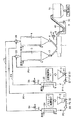
図1は、上記した塊状成型物48を得るのに好適な廃棄物処理システムの概略図である。プラスチック廃棄物41を粉砕してフレーク状にする粉砕機2と、粉砕されフレーク状に形成されたプラスチック廃棄物41を粉砕機2から吸い込む第一ベンチュリー32と、フレーク状のプラスチック廃棄物41を補集する第一サイクロン28と、粉砕されてフレーク状に形成されたプラスチック廃棄物41を二軸押出機1で溶融混練する前に加温する第一保温サイロ4と、有害廃棄物47を投入することができる灰投入ホッパー3と、灰投入ホッパー3から投入された有害廃棄物47を吸い込む第二ベンチュリー33と、有害廃棄物47から異物を除く第二サイクロン29と、有害廃棄物47を二軸押出機1で溶融混練する前に加温する第二保温サイロ5と、前記第一ベンチュリー32から前記第一サイクロン28まで有害廃棄物47を加温空気で空気輸送する配管P8と、前記第一保温サイロ4から二軸押出機1へプラスチック廃棄物41を一定量供給する第一定量供給機6と、前記第二保温サイロ5から二軸押出機1へ有害廃棄物47を一定量供給する第二定量供給機7と、前記第一定量供給機6から流入したプラスチック廃棄物41と前記第二定量供給機7から流入した有害廃棄物47とを溶融混練して溶融混練物を形成する二軸押出機1と、溶融混練物を押出して所定形状に成型して成型物を形成する押出用ダイ8と、成型物を冷却して塊状成型物48を形成する冷却水槽9と、塊状成型物48を貯蔵するストレージホッパー10とを有して構成される。
【0134】
粉砕機2にてフレーク状に粉砕されたプラスチック廃棄物41は、粉砕機2から配管P1を経由して第一ベンチュリー32により空気輸送により吸い出される。その後、第一ベンチュリー32から配管P2を経由して第一サイクロン28に空気輸送導入され、第一サイクロン28にて捕集される。第一サイクロン28から、フレーク状のプラスチック廃棄物41は、第一保温サイロ4に一時的に貯蔵される。第一サイクロン28から回収される空気は配管P3を経由して第一循環空気加熱器24に導入され昇温される。第一循環空気加熱器24に流入する循環空気は、焼却炉もしくは溶融炉からの廃熱を利用することで、昇温することが可能であり、そのような廃熱を利用する場合にあっては非常に経済的である。第一循環空気加熱器24から排出された空気は配管P5を経由して第一ブロワー26に導入され循環空気の流れを形成する。第一ブロワー26から排出された循環空気は配管P6を経由して第一ベンチュリー32に流入し、粉砕機2から配管P1を経由して空気輸送されるフレーク状のプラスチック廃棄物41と混入し、再度、配管P2を流れる。
【0135】
本発明に係る廃棄物処理システムでは、プラスチック廃棄物41を、前記プラスチック廃棄物41を粉砕する粉砕機2から、前記プラスチック廃棄物41を保温状態で貯蔵する第一保温サイロ4まで、加熱空気で空気輸送する構成を採用するので、プラスチック廃棄物41に付着している水分を空気輸送すると同時に乾燥させることが可能である。水分を含んだプラスチック廃棄物41が二軸押出機1内に流入すると、二軸押出機1内で水蒸気になり、溶融混練中に溶融混練物中に水蒸気が封入されると、塊状成型物中に気泡を有する原因になる可能性がある。また、水分を含んだプラスチック廃棄物41が二軸押出機1内に流入すると、二軸押出機1内で発生する塩酸ガスを吸収して生成した塩酸や、ばいじん中に含まれている塩類が二軸押出機1を腐食させる原因となる可能性がある。したがって、プラスチック廃棄物41を加熱空気で空気輸送することで空気輸送すると同時に乾燥させることができそのような不利益を防止することができるのである。プラスチック廃棄物41の乾燥状態としては、プラスチック廃棄物41中に含有される水分が3質量%以下であることが好ましく、より好ましくは1質量%以下であることが良い。
【0136】
また、灰投入ホッパー3から投入された有害廃棄物47は、灰投入ホッパー3から配管P7を経由して第二ベンチュリー33により空気輸送により吸い出される。その後、第二ベンチュリー33から配管P8を経由して第二サイクロン29に空気輸送導入され、第二サイクロン29にて捕集される。第二サイクロン29から、有害廃棄物47は、第二保温サイロ5に一時的に貯蔵される。第二サイクロン29から回収される空気は配管P9を経由して第二循環空気加熱器25に導入され昇温される。第二循環空気加熱器25に流入する循環空気は、焼却炉もしくは溶融炉からの廃熱を利用することで、昇温することが可能であり、そのような廃熱を利用する場合にあっては非常に経済的である。第二循環空気加熱器25から排出された空気は配管P11を経由して第二ブロワー27に導入され循環空気の流れを形成する。第二ブロワー27から排出された循環空気は配管P12を経由して第二ベンチュリー33に流入し、灰投入ホッパー3から配管P7を経由して空気輸送される有害廃棄物47と混入し、再度、配管P8を流れる。
【0137】
本発明に係る廃棄物処理システムでは、有害廃棄物47を、前記有害廃棄物47を投入する灰投入ホッパー3から、前記有害廃棄物47を保温状態で貯蔵する第二保温サイロ5まで、加熱空気で空気輸送する構成を採用するので、有害廃棄物47に付着している水分を空気輸送すると同時に乾燥させることが可能である。有害廃棄物47の乾燥状態としては、有害廃棄物47中に含有される水分が3質量%以下であることが好ましく、より好ましくは1質量%以下であることが良い。
【0138】
配管P3の途中からは配管P4が分岐して設けられており、配管P4には第一圧力調整弁34が設けられている。配管内の圧力が高くなった場合には、第一圧力調整弁34を開くことにより、配管P4から循環空気を排気することで、循環空気の圧力を所定値に保つことが可能である。また、配管P9の途中からは配管P10が分岐して設けられており、配管P10には第一圧力調整弁35が設けられている。配管内の圧力が高くなった場合には、第一圧力調整弁35を開くことにより、配管P10から循環空気を排気することで、循環空気の圧力を所定値に保つことが可能である。
【0139】
配管P1、配管P2、配管P3、配管P4、配管P5および配管P6内を流入する循環空気の空気温度は、120〜150℃に設定されている。循環空気内の温度を150℃よりも大きく設定した場合には、配管内を通流するフレーク状のプラスチック廃棄物41が溶解して配管の内壁に溶着する可能性があるからである。また、循環空気内の温度を120℃よりも小さく設定した場合には、フレーク状のプラスチック廃棄物41の乾燥効果が十分ではないからである。一方、配管P7、配管P8、配管P9、配管P10、配管P11および配管P12内を流入する循環空気の空気温度は、120〜180℃に設定されている。循環空気内の温度を180℃よりも大きく設定した場合には、配管内を通流する有害廃棄物47の温度が高くなりすぎると、二軸押出機内でプラスチック廃棄物41と溶融混練させた時に温度が上がりすぎて樹脂が分解する可能性があるからである。また、循環空気内の温度を120℃よりも小さく設定した場合には、有害廃棄物47の乾燥効果が十分ではないからである。
【0140】
前記第一保温サイロ4に貯蔵されたプラスチック廃棄物41は、所定の温度に保温されながら貯蔵される。所定の温度に保温されることで二軸押出機1内に流入する前に予備昇温させることができ、そのため二軸押出機1内での溶融混練が容易になるのである。前記第一保温サイロ4は、プラスチック廃棄物41を貯蔵する第一缶体と、前記第一缶体の外側面に巻回され、内部を蒸気が通流する第一蒸気パイプとを有する。第一蒸気パイプの中を通流する蒸気で前記第一缶体を外側から昇温することができるので、第一保温サイロ4に貯蔵されたプラスチック廃棄物41を保温することができるのである。なお、第一蒸気パイプの中を通流する蒸気は、焼却炉もしくは溶融炉の廃熱を利用することが可能であり、廃熱を利用した場合にあっては加熱エネルギーの消費を抑えることが可能になるのである。
【0141】
また、前記第二保温サイロ5に貯蔵された有害廃棄物47は、所定の温度に保温されながら貯蔵される。前記第二保温サイロ5は、有害廃棄物47を貯蔵する第二缶体と、前記第二缶体の外側面に巻回され、内部を蒸気が通流する第二蒸気パイプとを有する。第二蒸気パイプの中を通流する蒸気で前記第二缶体を外側から昇温することができるので、第二保温サイロ5に貯蔵されたプラスチック廃棄物41を保温することができるのである。なお、第二蒸気パイプの中を通流する蒸気は、焼却炉もしくは溶融炉の廃熱を利用することが可能である。
【0142】
前記第一保温サイロ4に貯蔵されたプラスチック廃棄物41は、第一定量供給機6より一定量二軸押出機1に供給される。前記第二保温サイロ5に貯蔵された有害廃棄物47は、第二定量供給機7より一定量二軸押出機1に供給される。そして、プラスチック廃棄物41と有害廃棄物47とは二軸押出機1内にて混合されて廃棄物混合物が形成されるのである。
【0143】
プラスチック廃棄物41と有害廃棄物47とを混合し廃棄物混合物を形成する廃棄物混合手段は、前記粉砕機2と、前記第一保温サイロ4と、前記灰投入ホッパー3と、前記第二保温サイロ5と、前記第一定量供給機6と、前記第二定量供給機7とを有して構成され、プラスチック廃棄物41と有害廃棄物47との混合は、第一定量供給機6からのプラスチック廃棄物41と第二定量供給機7からの有害廃棄物47とが二軸押出機1内に混入される段階で行なわれる。溶融混練物を形成する溶融混練手段は二軸押出機1を有して構成される。溶融混練物を押出し成型して成型物を形成する押出成型部は、押出用ダイ8を有して構成される。成型物を冷却させて塊状成型物48を得る冷却部は、冷却水槽9を有して構成される。
【0144】
また、プラスチック廃棄物41と有害廃棄物47とを混合し廃棄物混合物を形成する廃棄物混合工程は、第一定量供給機6からの廃棄物プラスチックと第二定量供給機7からの有害廃棄物とが二軸押出機1内に混入される工程である。なお、第一定量供給機6からのプラスチック廃棄物41と第二定量供給機7からの有害廃棄物47とが二軸押出機1にそれぞれ混入される前に、両者が十分に混合するように攪拌装置を内蔵した混合槽を設けることも可能である。かかる場合は、第一定量供給機6からのプラスチック廃棄物41と第二定量供給機7からの有害廃棄物47とが混合槽内に混入される工程が廃棄物混合工程となる。
【0145】
廃棄物混合工程において、プラスチック廃棄物41と有害廃棄物47との混合が、重量比で1:0.25〜1:4であることが好適である。プラスチック廃棄物41に対して有害廃棄物47の含有割合が0.25よりも小さい場合には、有害廃棄物47の含有割合が少なく、多量の有害廃棄物を適切に処理する観点からは不十分である。また、プラスチック廃棄物41に対して有害廃棄物47の含有割合が4よりも大きい場合には、塊状成型物におけるプラスチック廃棄物の含有量が少なくなり、その結果、有害廃棄物中における有害成分を塊状成型物中に強固に封入することが困難となる可能性がある。
【0146】
貯留場49は、本発明に係る塊状成型物48を専用で貯留する設備であることが好適である。本発明に係る塊状成型物48からは、カルシウム塩や有害廃棄物がほとんど溶出しない。そのため、雨水などが貯留場49に注ぐことにより発生する貯留場49から流出する排水には、カルシウム塩や有害廃棄物がほどんど含有されておらず、仮にカルシウム塩などが含有されていたとしてもその含有量は極少量になる。したがって、貯留場49が、塊状成型物48のみを貯留する設備である場合にあっては、その貯留場49の劣化乃至破損が少なく、貯留場49の維持・管理費を極めて少なく抑えることができるのである。
【0147】
図3に示すように、プラスチック廃棄物41は、塩化ビニール廃棄物43と塩化ビニールを含まないプラスチック廃棄物42とを分別したプラスチック廃棄物であることが好適である。
【0148】
すなわち、プラスチック廃棄物41から、塩化ビニール廃棄物43と塩化ビニールを含まないプラスチック廃棄物42とを分別し、塩化ビニール廃棄物を含有しないプラスチック廃棄物42と有害廃棄物47とを混合し、廃棄物混合物を形成し、前記廃棄物混合物を溶融させ、混練を行ない、溶融混練物を形成し、前記溶融混練物を押出用ダイから押出し、成型させて成型物を形成し、前記成型物を冷却させ、塊状成型物48を得、前記塊状成型物48を貯留場49に貯留することができる。溶融混練工程において、塩化ビニール廃棄物43からは、塩化水素が発生する可能性がある。したがって、あらかじめプラスチック廃棄物41から、塩化ビニール廃棄物43と塩化ビニールを含まないプラスチック廃棄物42とを分別し、塩化ビニールを含まないプラスチック廃棄物42のみを利用することで、極めて安全に塊状成型物48を得ることが可能になり、しかも廃棄物処理システムに対し、塩化水素対策を考慮する必要性が無くなるから、廃棄物処理システムを安価かつ簡素に製造することが可能になる。
【0149】
一方、プラスチック廃棄物41から、塩化ビニール廃棄物43と塩化ビニールを含まないプラスチック廃棄物42とを分別し、塩化ビニール廃棄物43と有害廃棄物47とを混合し、廃棄物混合物を形成し、前記廃棄物混合物を溶融させ、混練を行ない、溶融混練物を形成し、前記溶融混練物を押出用ダイから押出し、成型させて成型物を形成し、前記成型物を冷却させ、塊状成型物48を得、前記塊状成型物48を貯留場49に貯留することができる。かかる場合は溶融混練工程における溶融温度は170〜190℃に設定することが好適である。溶融温度を170℃よりも低く設定した場合にあっては、有害廃棄物47と塩化ビニール廃棄物43との溶融混練が均一に行なうことが困難となる場合があるからであり、また、溶融温度を190℃よりも高く設定した場合にあっては、塩化ビニールが分解する結果、塩素ガスが発生することで極めて危険だからである。
【0150】
図2に示すように、二軸押出機1は、送りおよび余熱を行う供給部14と溶融および混練を行なう溶融混練部15とを有する。二軸押出機1は、廃棄物混合物を溶融させ、シリンダー本体内に軸方向に相互に回転可能に配設された二軸のスクリュー13、13で混練を行ない、溶融混練物を形成する。この工程が溶融混練工程となる。
【0151】
二軸押出機1にて、廃棄物混合物を溶融混練する際に、水蒸気などのガスが発生する場合がある。二軸押出機1内でガスが大量に発生した場合にあっては二軸押出機1内の圧力が上昇して溶融混練の条件が想定条件と相違する場合のみならず二軸押出機1が破損する可能性がある。そのため二軸押出機1には発生したガスを外部空間に排出させることができるガス排出器31を設けてある。
【0152】
次に、溶融混練物は、押出用ダイ8から押出され、成型させて成型物が形成される。この工程が押出成型工程となる。
【0153】
そして、成型物は冷却水槽9で水中内にて十分に冷却させて塊状成型物48が得られる。この工程が冷却工程となる。図1に示すように、冷却水槽9には、冷却水槽9の底部近傍に冷却水槽内に貯溜された冷却水を攪拌することができる攪拌器30が設けられている。押出用ダイ8から押出された成型物は高温状態であり、係る状態で冷却水槽9内に落下した場合、冷却水槽9に貯溜された冷却水の上部分の水温が上がることで成型物の冷却効果を低下させ、また下部分では冷却水が静止していると冷却効果が低くなる可能性がある。そこで、冷却水槽9の底部近傍に攪拌器30を設けることで冷却水槽9内の冷却水の温度を一定に保つとともに冷却効果を高めることが可能になるのである。その後、塊状成型物48はストレージホッパー10内に貯蔵される。
【0154】
そして、ストレージホッパー10内に貯蔵された塊状成形物48は、貯留場49に貯留される。この工程が貯留工程となる。
【0155】
図2は、二軸押出機1および押出用ダイ8の近傍を詳しく説明する図である。図2に示したように、この二軸押出機1は、プラスチック廃棄物41を第一定量供給機6から、そして、有害廃棄物47を第二定量供給機7から、それぞれ二軸押出機1のシリンダー本体12内に供給する。プラスチック廃棄物41と有害廃棄物47とは、シリンダー本体12内に軸方向に相互に回転可能に配設されたフルフライトと呼ばれる二軸のスクリュー13、13の間に入ることで混合され廃棄物混合物が形成される。そして、まず供給部14において、その廃棄物混合物の送りと余熱が行われる。次に、供給部14から送られた廃棄物混合物は、溶融混練部15にて、圧縮されてスクリューとの摩擦によって発熱し、溶融し、混練し溶融混練物が形成される。この際、溶融混練部15の下流側には、溶融混練部15での溶融混練物の混練度を調整するために、溶融混練部15での充填度を調整する開度調整可能なゲート部16が設けられている。溶融混練部15で溶融、混練された溶融混練物は、ゲート部16を通過して、搬送部17にて前方へ搬送されて、シリンダー本体12の側部に設けられた排出口18へ送られる。さらに、排出口18に接続された搬送部19を通り、ギアポンプ20にて下流側に圧送される。ギアポンプ20にて圧送された溶融混練物は、スクリーン21にて、異物などが除去された後、押出用ダイ8のダイ面に設けられた回転刃22にてカットするカット方式のペレタイザー23にて成型して、ペレット状に成形されて成型物となり、その後ペレットの分離搬出装置(図示せず)にて外部へと搬出されるようになっている。なお、二軸のスクリュー13、13を回転させるモーターはM1で示されており、回転刃22を回転させるモーターはM2で示されている。また、成型物は、ペレタイザー23にて成型してペレット状に形成したが、ペレット状の形状のみならず任意の形状に成型することも可能である。たとえば、二軸押出機1から押出用ダイ8を通して棒状に押出し、これを短く切断して冷却水中に投入することで塊状成型物48を得る成型であってもよい。その他、種々の粒状物、塊状物、板状物、棒状物、型材状品などに成型することが可能である。
【0156】
塊状成型物48は、質量、体積もしくは形状のうち少なくとも一つにおいて異なるものであることが好適である。すなわち、塊状成型物48は、質量、体積もしくは形状のうち少なくとも一つにおいて、一定の値を有するものでないことが好ましいのである。塊状成型物48は極めて劣化しにくい物質であるが、非常に長期間が経過した場合にあっては劣化する可能性がある。かかる場合、塊状成型物48の質量などが一定の値を有すると、塊状成型物48から有害廃棄物が環境内に一度に放出される可能性がある。そこで、塊状成型物48の質量、体積もしくは形状を不均一に設定しておくことで、塊状成型物の劣化速度を異なるように設定することができ、貯留した塊状成型物48が長期間経過後に、一度に劣化して有害廃棄物を環境内に放出させることは避けることができる。
【0157】
なお、塊状成型物48の質量、体積、形状を不均一に設定することは種々の手法を採用することが可能であり、たとえば、上述したように、成型物をペレタイザー23にて成型してペレット状に形成する過程において、不均一形状となるようにペレット状に成形すれば良いのである。
【0158】
前記供給部14の温度は、50〜150℃に設定されている。前記供給部14の温度が50℃よりも低いと廃棄物混合物の柔軟性が不十分で溶融混練部15への搬送が困難となるからであり、前記供給部14の温度が150℃よりも高いと廃棄物混合物の局所的加熱が発生する可能性があるからである。
【0159】
一方、前記溶融混練部15の温度は、180〜280℃に設定されている。前記溶融混練部15の温度が180℃よりも低いと溶融混練効果が不十分となるからであり、前記溶融混練部15の温度が280℃よりも高いとエネルギー的に非効率的であったり、樹脂が分解する可能性があるからである。
【0160】
前記二軸押出機1における二軸のスクリュー13、13は、非かみ合い型、部分かみ合い型、完全かみ合い型のいずれでも可能であるが、特に完全かみ合い型が好適である。本発明に係る廃棄物処理システムでは、二軸押出機1すなわち二軸スクリューを採用しているから、単軸スクリューと比較して、2本のスクリュー流路内の溶融混練物に対するセルフクリーニング作用があることが利点の一つとなる。また、本発明に係る廃棄物処理システムでは、二軸スクリューを採用しているから、たとえ非かみ合い型の二軸スクリュー構造であっても、単軸スクリュー押出機に比べて滞留層の存在は少なくなる。かみ合い型の二軸スクリュー構造を採用した場合にあっては、2本のスクリューのフライトが互いに接触しているために、スクリュー底部の滞留層をかきとる作用すなわちセルフクリーニング作用が二軸スクリューの形状および回転方向に応じて一層期待できることになる。
【0161】
前記二軸押出機における二軸のスクリューの回転方向は、同方向回転もしくは異方向回転のいずれであっても採用することが可能であるが、特に異方向回転が好適である。同方向回転二軸スクリューを採用した場合にあっては、一方のスクリューが他方のスクリュー底部に沿って移動し、機械的なセルフクリーニング作用が生じ易くなる。なお、機械的なセルフクリーニング作用は、同方向回転二軸スクリューの場合には、ボールネジ形やニーディングディスク形において、また、異方向回転の場合には、完全かみ合い型の台形ネジにおいて得られる。また、同方向回転二軸スクリューを採用した場合にあっては、1条ネジ(深溝)、2条ネジ(中間溝)もしくは3条ネジ(浅溝)のいずれであっても採用することが可能である。
【0162】
前記溶融混練工程において、溶融混練物に付与されるせん断速度が、826〜2165(1/sec)であるようにスクリュー回転数を設定することが好ましい。溶融混練物に付与されるせん断速度が、826(1/sec)よりも小さいと溶融混練効果が不十分であり、一方、2165(1/sec)よりも大きいと摩擦力が大きくなり、その結果、高熱が発生し樹脂が分解する可能性があるからである。
【0163】
前記二軸押出機におけるスクリュー長さとスクリュー径との比(L/D)は、24〜60であることが好ましい。L/Dが、24よりも小さいと溶融混練効果が促進されずプラスチック廃棄物と焼却廃棄物との溶融混練が不十分となる傾向にあるからであり、一方、L/Dが、60よりも大きいと溶融混練のために過剰なエネルギーを消費することになるからである。
【0164】
前記二軸押出機1では、各種ガスもしくは水蒸気の発生やポリ塩化ビニル(PVC)などが分解することで発生する塩素ガスが原因で、シリンダー本体12内の溶融混練部15や搬送部17の圧力が上昇することがある。そのため、前記二軸押出機1には、塩素ガス排除制御手段を設けることが可能である。すなわち、シリンダー本体12の搬送部17などに、開口部を設けるとともに、前記開口部に開口ボックスを形成し、この開口ボックスに塩素ガス排除ラインを接続させることが可能である。前記開口ボックスの内部には、圧力センサーが配設されており、圧力センサーに接続された圧力計によって、シリンダー12内の圧力が検知されるようになっている。そして、圧力計によって検知された圧力値に基づいて前記ガス排除ラインから各種ガスが排除されるのである。
【0165】
シリンダー本体12に、温度を検出できる温度検出部と、温度上昇を可能とする昇温部と、温度下降を可能とする冷却部とを設けることもできる。たとえば、前記シリンダー本体12を複数個の温度制御区域に分割し、各区域の外側面にヒーターを設けるとともに、シリンダー本体12の上側あるいは下側に熱伝対等の温度検出部を設け、シリンダー本体12内に供給される溶融混練物が熱分解しない程度の温度に設定することができる。前記冷却部としては、二軸押出機1のシリンダー本体12をジャケット化し、それぞれ適切な温度の水もしくは冷媒を各区域のジャケット内に循環させることで適切な冷却効果を持たせることが可能である。
【0166】
廃棄物混合手段において、プラスチック廃棄物41と有害廃棄物47との混合が、重量比で1:0.25〜1:4であることが好適である。プラスチック廃棄物41に対して有害廃棄物47の含有割合が0.25よりも小さい場合には、多量の有害廃棄物を適切に処理する観点からは不十分であり、有害廃棄物の処理としてのランニングコストが高くなる。また、プラスチック廃棄物41に対して有害廃棄物47の含有割合が4よりも大きい場合には、有害廃棄物中における有害成分を塊状成型物中に長期間にわたり封入することが困難となる可能性がある。
【0167】
本発明に係る廃棄物処理方法を実施することで塊状成型物48を得ることが可能である。前記塊状成型物48は、プラスチック廃棄物41と、焼却灰、ばいじん、汚泥もしくは汚染土壌のうち少なくとも一つを含む有害廃棄物47とを混合し、二軸押出機1で溶融混練を行ない、押出用ダイから押出し、成型させた後冷却させることで得られる塊状成型物48である。
【0168】
この塊状成型物48からは、有害廃棄物47中に含有される重金属イオンなどの有害廃棄物が極めて流出しにくい傾向にある。それは、有害廃棄物47中に含有される重金属イオンなどの有害廃棄物が塊状成型物48の内部に封入されていることと、塊状成型物48が極めて強固で割れにくいことにある。
【0169】
前記塊状成型物48は、上述したように有害廃棄物47を強固に封印し、その内部に含有される有害廃棄物を物理的化学的に安定させるのである。また、この塊状成型物48は、圧力、衝撃による破壊や土壌菌、紫外線、酸性雨などによる劣化には極めて強い性能を有する。なるほど、前記塊状成型物48は約10〜50年程度の長期の期間では徐々に劣化し、塊状成型物表面には、はがれやひび、割れ目などが生じ、その表面に生じた割れ目などから内部に封入された有害廃棄物が流出する可能性はあるかもしれないが、有害廃棄物47をセメントで固めた場合と比較すると、セメントで固めた場合のように、一定時間経過後、短期間で次々と崩壊やひび割れ、風化するような現象は考えられないので、有害廃棄物が一挙に自然環境中に流出するようなことはない。本発明に係る塊状成型物48に仮に劣化が生じたとしても、成型物の材料配合比、強度、形状、サイズなどの違いによって、個々の成型物の劣化速度が各々異なるため有害廃棄物が外部に流出するにしても長期間にわたって拡散され、また微量に収まるため、国民生活や自然環境中に悪影響を及ぼす可能性は極めて低いと考えられる。
【0170】
前記塊状成型物48の圧縮強度を測定したところ600〜1500kgf/cm2であり、天然石の圧縮強度よりも大きいものであった。本発明に係る塊状成型物48をハンマーで粉々に粉砕しようとするとかなりの時間と力を要するほど硬いものであった。
【0171】
また、本発明に係る塊状成型物48を水中に1年間放置しておいても有害廃棄物47中の重金属類の水中への流出はほとんどなかった。また、1年間放置後の水のPhに変化はなく中性のままであった。さらに、本発明に係る塊状成型物48を塩水中に1年間放置した場合や、pH4程度の酸性水中に1年間放置しておいても有害廃棄物47中の重金属類の水中への流出はほとんどなかった。
【0172】
溶出試験としての環境庁告示第13号試験は、処分場に持ち込まれる各種有害廃棄物やセメントなどで有害廃棄物を固化した固化物が、何らかの圧力や衝撃により破壊されたり、ひび割れを起こすことや、長年の間にはその大半が風化もしくは劣化することを前提に固化物を5mm以下に粉砕し、5mm以下の破片や粉体からの重金属類などの溶出値を測定することを義務付けている。本発明に係る塊状成型物48を環境庁告示第13号試験で試験した場合でも、有害廃棄物の流出は極少量に抑制することができ、法定の埋立基準値内に収まるものであった。
【0173】
環境庁告示13号試験法とは、試料を粒径5mm以下に粉砕し、これに10倍の純水を加えて固液比10とし、6時間振とうした後、液をフィルターでろ過して、得られた溶液中の物質の濃度を測定する試験方法である。
【0174】
焼却炉から排出されたばいじんを純水で練って乾燥固化させたものについて環境庁告示13号試験を行い、鉛成分の溶出量を測定した。
【0175】
一方、ポリエチレンテレフタレート(PET)廃棄物100g(85.5質量%)と、焼却炉から排出されたばいじん(14.5質量%)とを、本発明に係る廃棄物処理方法を使用して二軸押出機1で溶融混練することで塊状成型物48を得た。この塊状成型物48に対して、環境庁告示13号試験を行い、鉛成分の溶出量を測定した。
【0176】
焼却炉から排出されたばいじんを比較例とし、一方、本発明に係る塊状成型物48を本発明として、それらの試験結果を下記に示す表1に示す。
【0177】
【表1】

比較例の場合、鉛の溶出量は48ppmであり、鉛溶出量は高い値を示すのに対して、本発明の場合、塊状成型物48からの鉛の溶出量は0.01ppm以下であり、鉛溶出量は相当に低い値を示した。したがって、本発明の場合の塊状成型物48では、比較例と比較して鉛の溶出量減少率は99.98%以上である。成型物を粒径5mm以下にして行なう厳しい溶出試験において溶出量が0.01ppm以下であるということから、表面積の小さい塊状成型物のままでの溶出量はほとんど0に等しいと考えられる。本発明に係る塊状成型物48を保管したしても環境保全面において充分安全であると考えられる。上記のように、このシステムで得られる塊状成型物48は、特にプラスチックが緻密で、かつばいじんなどが均等に分散しているので、たとえ、粒子状になったとしても、有害廃棄物は溶出せず、自然環境と同じもしくは環境基準値以下に収まる可能性の高いものである。
【0179】
したがって、このシステムで形成した塊状成型物は、貯留以外に、自然界への放置57も可能であるし、土木工事資材56として用いることも可能である。また、貯留場49で貯留された塊状成型物48は土木工事資材56として使用することができる。土木工事資材56としては、具体的には、道路工事用路盤材、高架道路用路床材、高速道路用防音材、公共建築物の屋上防水板材、干拓工事用資材、廃棄物処分場建築用資材、海上処分場建築用資材、護岸用ブロック資材、海上空港建設工事用資材などに使用することができる。
【0180】
このように本発明に係る塊状成型物48は、強い強度を有し、砕石や砂利の代替品として使用できるように製造過程において任意の形状およびサイズなどを意図的に変えられる工夫が施されているので、路盤材、埋め戻し材、アスファルト・コンクリートの骨材などとしてあらゆる場所において幅広く活用することができる。
【0181】
前記塊状成型物の平均粒径は5mm以下であることが好適である。塊状成型物の平均粒径を5mm以下とすることにより、塊状成型物のかさ比重を小さくすることができ、塊状成型物を保管する際に、充填率を向上させることができるのである。また、塊状成型物の平均粒径を5mm以下とすることにより、塊状成型物の混錬と分散を向上させることができる。また、塊状成型物の平均粒径を5mm以下とすることにより、塊状成型物の取扱性、輸送性および作業性を向上させることができる。さらに、塊状成型物の平均粒径を5mm以下とすることにより、塊状成型物の落下強度を向上させることができる。また、塊状成型物の平均粒径を5mm以下とすることにより、塊状成型物の破断面がでないよう加工することが容易となる。さらに、塊状成型物の平均粒径が5mm以下とした場合にあっては、塊状成型物を溶融炉に投入する際、溶融炉の横側投入口より空気圧送で瞬時かつ連続的に塊状成型物を投入することができるのである。また、塊状成型物の平均粒径が5mm以下とした場合にあっては、塊状成型物を溶融炉に投入すると、溶融炉内下部で瞬時にガス化させやすくなる。なお、塊状成型物の平均粒径が5mm以下であるということは、JIS規格で定められた5mmメッシュで作られた篩を通過するということである。なお、前記塊状成型物の平均粒径は3mm以上5mm以下とすることがより好適である。
【0182】
また、前記塊状成型物の表面に、前記有害廃棄物が流出しないように表面処理がなされていることが好適である。表面処理としては、硫酸アルミニウム水溶液を用いて塊状成型物の表面を処理することができる。すなわち、塊状成型物を硫酸アルミニウム水溶液中に浸漬させることにより、塊状成型物の表面にたとえ有害廃棄物が付着していたとしても、その有害廃棄物を不溶性化合物に化学変化させることができるのである。
【0183】
また、表面処理として塊状成型物を再加熱することにより、プラスチック樹脂を再度溶解させ、有害廃棄物を完全に溶融したプラスチック樹脂により覆うことができる。なお、再加熱は塊状成型物を180〜200℃にて4〜5分間加熱することが好適である。
【0184】
前記塊状成型物中に、前記有害廃棄物を難溶化させる無機系粉粒状物を含有することが好ましい。前記無機系粉粒状物は、セメント類、シリカ、アルミナ、マグネシウム、カルシウム、鉄などを含有する無機系粉粒体である。また、前記無機系粉粒状物は、300℃程度の温度でも分解せず、溶解せず、かつ、腐食しないものが好ましい。前記無機系粉粒状物は、前記有害廃棄物に対して、5〜30質量%で含有させることが好ましく、より好ましくは5〜20質量%の割合で含有させることが好適である。
【0185】
前記塊状成型物中に、オイル成分を含有することが好ましい。これにより、塊状成型物の撥水性を向上させることができる。塊状成型物の撥水性を向上させることができるから、たとえ塊状成型物に雨水などがあたったとしても、有害廃棄物が水に溶けて環境中に流出することはないのである。オイル成分としては、撥水性と耐熱性とを有するものが好適であり、具体的にはシリコンオイルなどを使用することが可能である。シリコンオイルは、水で希釈した3〜5質量%程度の希釈液として使用することが好適である。
【0186】
プラスチック廃棄物41と有害廃棄物47との混合が、重量比で1:0.25〜1:4であることが好適である。プラスチック廃棄物41に対して有害廃棄物47の含有割合が0.25よりも小さい場合には、有害廃棄物の処理としてのランニングコストが高くなる。また、プラスチック廃棄物41に対して有害廃棄物47の含有割合が4よりも大きい場合には、有害成分を長期間にわたり封入することが困難となる可能性がある。
【0187】
本発明に係る廃棄物処理方法は、行政区域内で発生する産業廃棄物もしくは一般廃棄物を、前記行政区域内に存在する焼却炉53で焼却処理するもしくは前記行政区域内に存在する溶融炉54で溶融処理することで発生する焼却廃棄物と、前記行政区域内で発生するプラスチック廃棄物41とを混合して廃棄物混合物を形成する廃棄物混合工程と、前記廃棄物混合物を溶融混練を行なって溶融混練物を形成する溶融混練工程と、前記溶融混練物を押出用ダイから押出し、成型させて成型物を形成する押出成型工程と、前記成型物を冷却させて塊状成型物48を得る冷却工程と、前記塊状成型物48を、前記行政区域内の土木工事事業における土木工事資材56として使用することで、前記焼却廃棄物および前記プラスチック廃棄物を再利用する再利用工程とを有する。
【0188】
行政区域内で発生する焼却廃棄物とプラスチック廃棄物41とを混合し、溶融混練し、押出し成型した後、冷却して塊状成型物48をつくり、それを前記行政区域内の前記土木工事事業における土木工事資材56として再利用することで、行政区域単位での自己完結型の廃棄物処理が可能になる。すなわち、行政区域内において収集した廃棄物40の大半であるプラスチック廃棄物41を分別して取出して粉砕する。残りの可燃ゴミなどを燃やして出る焼却灰45やばいじん44をプラスチック廃棄物41と混合し、溶融混練し、押出し成型した後、冷却して塊状成型物48をつくり、塊状成型物48を採石などの代わりに道路工事の路盤材や埋め戻し材などに使用することで、行政区域における支配権を有する団体は、それだけ廃棄物40の処理コストの低減を図ることが可能になる。なお、行政区域における支配権を有する団体とは、国内の一部を区域とし、その区域内に居住する住民に、法律の範囲内で自治的に支配権をもつ団体であり、たとえば、地方公共団体である。また、行政区域とは、上述した支配権を有する団体に統治される国内の区切りを付けた範囲であり、たとえば、都道府県や市町村などが該当する。また、廃棄物40とは、行政区域内で発生する産業廃棄物・一般廃棄物、さらに行政区域内で発生するプラスチック廃棄物を含む。
【0189】
前記プラスチック廃棄物41と前記焼却廃棄物とを混合し、溶融混練し、押出し成型した後、冷却して塊状成型物48をつくり、それを土木工事事業における土木工事資材56として再利用することで、前記プラスチック廃棄物41および前記焼却廃棄物を最終処分場などに埋め立てる必要性がほとんどなくなるので、そのような最終処分場の延命化が図れることになる。
【0190】
また、本発明に係る廃棄物処理方法は、行政区域内で発生する産業廃棄物もしくは一般廃棄物を、前記行政区域内に存在する、焼却炉53で焼却処理するもしくは溶融炉54で溶融処理することで発生する焼却廃棄物と、前記行政区域内で発生するプラスチック廃棄物41とを混合して廃棄物混合物を形成する廃棄物混合工程と、前記廃棄物混合物に対し溶融混練を行なって溶融混練物を形成する溶融混練工程と、前記溶融混練物を押出用ダイから押出し、成型させて成型物を形成する押出成型工程と、前記成型物を冷却させて塊状成型物48を得る冷却工程と、前記塊状成型物48を前記行政区域内に存在する前記溶融炉54の燃料として使用することで、前記焼却廃棄物および前記プラスチック廃棄物41を再利用する再利用工程とを有する。
【0191】
前記塊状成型物48を溶融炉54の燃料に使用した場合、塊状成型物48中に含有される焼却灰45、ばいじん44の量は、溶融工程でその約95%(重量比)が溶融スラグに生まれ変わる。そして、溶融スラグは、水冷もしくは空冷などの冷却手段により冷却されて冷却固化物となる。焼却灰45やばいじん44などの有害物は冷却固化物中に封入されるので有害物は環境外に流出しない。したがって、前記塊状成型物48を溶融炉54の燃料として使用して溶融スラグ化し、その溶融スラグは土木工事資材56として有効利用することが可能である。
【0192】
また、本発明に係る廃棄物処理方法は、行政区域内で発生する有害廃棄物と、前記行政区域内で発生するプラスチック廃棄物41とを混合し、廃棄物混合物を形成する廃棄物混合工程と、前記廃棄物混合物を溶融混練を行なって溶融混練物を形成する溶融混練工程と、前記溶融混練物を押出用ダイから押出し、成型させて成型物を形成する押出成型工程と、前記成型物を冷却させて塊状成型物48を得る冷却工程と、前記塊状成型物48を前記行政区域内で貯留する貯留工程とを有する。
【0193】
焼却灰、ばいじん、汚泥、汚染土壌などを廃棄するすなわち捨てるという考え方では、有効利用可能な国土は有限であるため、近い将来にゴミや有害物の廃棄場が不足して国全体としても環境保全上の重大な問題になる可能性がある。また、昨今、プラスチック廃棄物の発生量が多くなりこのプラスチック廃棄物41を処分することは重大な問題であり、従来のプラスチック廃棄物41を捨てるという考え方では、上述したように最終廃棄場の不足により国全体としても環境保全上の重大な問題になる可能性がある。特にプラスチック廃棄物41の中でもペットボトル(ポリエチレンテレフタレート)の廃棄物の量は増大する傾向にある。
【0194】
そこで、従来の廃棄するという考え方を保管するという考え方に発想を転換するのである。もっとも年間5000万トン以上も発生すると考えられる都市ゴミの全てを有効利用することは困難であるので、都市ゴミの半分以上を占めるプラスチック廃棄物41を分離した後、残りを焼却して発生した焼却灰45やばいじん44などの有害廃棄物47とプラスチック廃棄物41とを混合して溶融混練させ、押出し成形して冷却することで塊状成型物48を作り、これを一旦保管するのである。保管した塊状成型物48は公共事業などにおいて使用することが可能である。
【0195】
なお、前記溶融混練工程は、送りおよび余熱を行う供給部と溶融および混練を行なう溶融混練部とを有する二軸押出機1で、前記廃棄物混合物を溶融させ、シリンダー本体内に軸方向に相互に回転可能に配設された二軸のスクリューで混練を行ない、溶融混練物を形成する溶融混練工程であることが好適である。
【0196】
有害廃棄物47とプラスチック廃棄物41とを混合し、二軸押出機で溶融混練し、押出し成型した後、冷却して生成した塊状成型物48は、圧縮強度が600〜1500kgf/cm2であり、天然石以上に強靭で、高い圧力や衝撃にも十分耐えることができる。このため、前記塊状成型物48は、行政区域内の土木工事事業における土木工事資材56として使用することが可能となり、具体的には、道路工事用路盤材、高架道路用路床材、高速道路用防音材、公共建築物の屋上防水板材、干拓工事用資材、廃棄物処分場建築用資材、海上処分場建築用資材、護岸用ブロック資材、海上空港建設工事用資材などに使用することができる。なお、ここで海上空港建設工事用資材とは、空港建設など海上で人工造成される施設に使用する建設工事用資材をいう。また、たとえ塊状成型物が壊れたとしても数個の破片に分割する程度であり、コンクリートが破損する場合のように細片に分割しない。したがって、塊状成型物が壊れたとしても、その破損面から有害廃棄物が比較的微量に溶出するにすぎず、環境基準を超えるような水質汚染や地下水汚染の原因となることはない。
【0197】
前記プラスチック廃棄物41としては、ポリエチレン、ポリプロピレン、ポリスチレン、AS樹脂、ABS樹脂、塩化ビニル樹脂、メタクリル樹脂、ポリエチレンテレフタレート、ポリ塩化ビニリデン、エチレンビニルアルコールコポリマー、ACS樹脂、ASA樹脂、AES樹脂などの汎用プラスチックの廃棄物を利用することが可能である。
【0198】
行政区域内で発生する廃棄物の大半はプラスチック廃棄物41であり、たとえば、都市ゴミの中には容積で約30〜50%(重量比で7〜12%)のプラスチック廃棄物41が混入している。本発明に係る廃棄物処理方法では、プラスチック廃棄物41を焼却しないで、前記有害廃棄物47とを混合し、溶融混練し、押出し成型した後、冷却して塊状成型物48をつくり、それを土木工事事業における土木工事資材56として再利用するから、焼却させることに伴なう二酸化炭素発生量を大幅に抑制させることが可能である。したがって、各行政区域における環境保全に一層貢献することが可能である。
【0199】
さらに、本発明に係る廃棄物処理方法では、行政区域内で発生する焼却廃棄物とプラスチック廃棄物とを混合し、溶融混練し、押出し成型した後、冷却して塊状成型物48をつくり、それを前記行政区域内の前記土木工事事業における土木工事資材56として再利用することで、行政区域内で発生した焼却廃棄物やプラスチック廃棄物41を遠方の最終処分場まで輸送させる必要性はない。したがって、焼却廃棄物やプラスチック廃棄物41のような本来的に価値のないものに多量の輸送エネルギーを使用する必要性はない。
【0200】
金属成分を含有する廃棄物と、溶融したプラスチック廃棄物とを混練し、冷却固化することにより塊状成型物とし、前記塊状成型物を備蓄した後、前記塊状成型物から金属成分を回収することができる。ここで、塊状成型物を備蓄するとは、塊状成型物中に含有される金属成分を将来的に取り出して有効利用することを意図して、塊状成型物を長期間貯留することをいう。
【0201】
前記廃棄物は、有害廃棄物と、生物体内もしくは環境中に及ぼす影響が少ないもしくは無いとされる非有害廃棄物とを含むものである。より具体的には、前記廃棄物は、有害金属成分と、生物体内もしくは環境中に及ぼす影響が少ないもしくは無いとされる非有害金属成分とを含むものである。
【0202】
焼却灰、ばいじんなどの廃棄物から含有する金属成分を回収することは、現状においてはコストが高く、商業的には実用化されていない。しかしながら、採掘可能な金属の埋蔵量には限りがあり、特に埋蔵量が少ない金属については将来的に、廃棄物から金属成分を回収する手法を実現させる必要性が生じる。
【0203】
そこで、本発明においては、金属成分を含有する廃棄物をいったん塊状成型物の状態で備蓄しておき、必要に応じてこの塊状成型物から含有する金属成分を回収するわけである。含有する金属成分は塊状成型物中に封入されているので、たとえその金属成分が有害金属成分であっても自然界に影響を及ぼすことはない。
【0204】
また、このようにすれば、前記塊状成型物を処分場に備蓄した場合、含有する金属成分を回収した塊状成型物の分だけ処分場のスペースがあくので、ここを再度処分場として再利用することができる。
【0205】
前記備蓄は上述した処分場ばかりでなく、備蓄を目的として設けられた貯留場所で行うことが可能である。特に非有害廃棄物のみからなる廃棄物を備蓄する場合は野積みも可能である。
【0206】
なお、金属成分の回収を必要とする廃棄物と、金属成分の回収を必要としない廃棄物とを同じ処分場に廃棄した場合、必要な金属成分の回収にあたっては、他の廃棄物や覆土に使用された土砂などと分離する必要性が生じ、さらには分離されたものを遠隔地にある精錬所まで運ぶ必要がある。したがって、備蓄に際しては、金属成分の回収を必要とする廃棄物のみを備蓄することが好適である。
【0207】
有害廃棄物は、焼却炉もしくは溶融炉などから排出される焼却灰、ばいじんなどの焼却廃棄物、汚泥、汚染土壌、スラッジなどの有害廃棄物を含むとともに、さらに、アルミ鉱滓(アルミドロス)、石炭灰、シュレッダーダスト、廃石膏ボートなどを含有させることが可能である。特に、産業廃棄物もしくは一般廃棄物を焼却炉で焼却することで発生する焼却灰もしくはばいじんや、溶融炉より発生するばいじんには、亜鉛成分や鉛成分などが比較的多く含有されている場合がある。したがって、焼却炉や溶融炉から発生するばいじんや焼却灰と、溶融したプラスチック廃棄物とを混練し、冷却固化することにより塊状成型物とすれば、極めて安全に長期間にわたり塊状成型物を備蓄した後、前記塊状成型物から高回収率にて亜鉛成分や鉛成分を回収することができるのである。
【0208】
アルミ鉱滓(アルミドロス)とは、アルミ製品を製造する過程で、アルミの地金やスクラップを溶解した際に溶湯面上に生成される不純物である。アルミ鉱滓(アルミドロス)は、溶解方法や原料の種類によって左右されるが、溶解原料量に対しておよそ2〜10%程度発生する。アルミドロスはそのままでは使用できないため、通常は溶解炉から取り除かれるものの、この中には再利用できる金属アルミ成分が6割程度と多く含有されている。アルミドロスは国内で年間35万トン程度発生しており、アルミ地金のほとんどを海外に依存しているわが国では、金属アルミ分を高い効率で回収できる技術の確立が重要な課題となっているものの、バーナー式回転炉のような従来の処理方法では、処理中の酸化反応によって金属アルミ成分が減少するなどの理由により、アルミ成分の回収率は40〜60%が限度である。また、アルミ成分回収後に発生する年間約10万トンの残灰は、その大半が産業廃棄物として管理型処分場に埋め立て処分されているが、処分場の確保が困難になってきたことや廃棄処分費用の高騰などが顕在化しているほか、残灰中に含まれる窒化物などが水と反応して刺激臭を伴うアンモニアガスが発生するため、抜本的な再資源化対策が急務となっている。そこで、アルミドロスと、溶融したプラスチック廃棄物とを混練し、冷却固化することにより塊状成型物とすれば、極めて安全に長期間にわたり塊状成型物を備蓄した後、前記塊状成型物から高回収率にてアルミ成分を回収することができるのである。すなわち、この方法によれば、処分場確保の問題を解決しながらしかも高回収率にてアルミ成分を回収することができるのである。
【0209】
石炭灰とは、火力発電所から発生する焼却灰の一種であり、年間60万トンに達し、この有効利用を図ることが求められている。石炭灰の主成分は、シリカ、アルミナであり、アルミナは石炭灰中に約70%程度も含有されるものである。この石炭灰についても、同様に、石炭灰と、溶融したプラスチック廃棄物とを混練し、冷却固化することにより塊状成型物とすれば、極めて安全に長期間にわたり塊状成型物を備蓄した後、前記塊状成型物から高回収率にてアルミ成分を回収することができるのである。この方法によれば、処分場確保の問題を解決しながらしかも高回収率にてアルミ成分を回収することができる。
【0210】
シュレッダーダストとは、広く産業廃棄物をシュレッダーにて裁断した廃棄物をいい、たとえば自動車のシュレッダーダストには、銅が金属成分として含有されている。この自動車のシュレッダーダストは従来リサイクルできずに埋め立て処分されているものであるが、このシュレッダーダストについても、同様に、シュレッダーダストと、溶融したプラスチック廃棄物とを混練し、冷却固化することにより塊状成型物とすれば、極めて安全に長期間にわたり塊状成型物を備蓄した後、前記塊状成型物から高回収率にて銅成分を回収することができるのである。この方法によれば、処分場確保の問題を解決しながらしかも高回収率にて銅成分を回収することができる。
【0211】
廃石膏ボードとは、石膏ボードの廃棄物である。石膏ボードとは、石膏の薄い板の両面にやや厚手の紙を貼ったもので、軽くて加工の容易な建築資材である。石膏ボードは、断熱性、遮音性、そして防火性に優れ、準不燃材料の代表的なものとして多く活用されています。廃石膏ボードには、砒素やカドミウムなどが含有されており、近年、建築物の解体に伴う廃石膏ボードの増加により、その処理方法が大きな環境問題になっている。しかしながら、この廃石膏ボードについても、同様に、廃石膏ボードと、溶融したプラスチック廃棄物とを混練し、冷却固化することにより塊状成型物とすれば、極めて安全に長期間にわたり塊状成型物を備蓄した後、前記塊状成型物から高回収率にて砒素成分やカドミウム成分を回収することができるのである。この方法によれば、処分場確保の問題を解決しながらしかも高回収率にて砒素成分やカドミウム成分を回収することができる。
【0212】
図5は、備蓄した塊状成型物から金属成分を回収する手段のフローチャートである。ここでは、焼却炉や溶融炉から発生するばいじんや焼却灰と、溶融したプラスチック廃棄物とを混練し、冷却固化させた塊状成型物から、亜鉛成分や鉛成分を回収する場合を一例にとり、説明をする。
【0213】
塊状成型物48を加熱炉(熱分解炉)70において、空気を遮断して加熱し、塊状成型物48のプラスチック成分を溶融、分解させ、分解ガス72と分解油73を得る。なお、加熱炉70において空気を遮断しての加熱は、450〜550℃程度にて行うことが好適である。
【0214】
加熱炉70の底部には、残渣(チアコール)74と灰分(焼却飛灰もしくは溶融飛灰)75とが残る。この残渣(チアコール)74と灰分(焼却飛灰もしくは溶融飛灰)75とを取り出して、それらの混合物を溶融炉54において高温の燃焼ガスによって加熱する。なお、溶融炉における加熱は1300〜1500℃程度において行うことが可能である。混合物を高温の燃焼ガスにて過熱した結果、酸化亜鉛ZnO76や酸化鉛PbO77などの金属酸化物78が得られる。これを集塵機で捕集して粉体状の金属酸化物78として回収する。一方、溶融炉54の底部において高温によって溶融した焼却飛灰もしくは溶融飛灰を水中に投入することで溶融スラグ58が得られる。
【0215】
次に、酸化亜鉛ZnO76と酸化鉛PbO77とを還元炉71において、コークス79を加え、加熱して還元することによって金属亜鉛粉末80と金属鉛81とが得られる。なお、還元炉71における加熱は1200〜1300℃にて行うことが可能である。
【0216】
上述した方法によると、金属成分の含有率が5%の焼却灰と廃プラスチックとが重量比で50対50の場合における塊状成型物1000kgを処理したとき、約25kgの金属亜鉛や金属鉛が得ることが可能である。
【0217】
この金属亜鉛と金属鉛の回収プロセスにおいて、加熱炉70における廃プラスチックの熱分解によって得られる分解ガス72を、加熱炉70自体の熱源や、溶融炉54や還元炉71の熱源として使用することによって、この金属回収装置の運転に必要な熱エネルギーのほとんどをまかなうことができることとなり、極めて経済的に運用することが可能となる。また、廃プラスチックの熱分解によって得られる分解油73は、精製することによって、ガソリン、軽油、灯油などの燃料として利用することが可能である。
【0218】
なお、今回開示された実施の形態はすべての点で例示であって制限的なものではないと考えられるべきである。本発明の範囲は上記した説明ではなくて特許請求の範囲によって示され、特許請求の範囲と均等の意味および範囲内でのすべての変更が含まれることが意図される。
【0219】
【発明の効果】
本発明に係る廃棄物処理方法を使用するもしくは本発明に係る廃棄物処理システムを実施することで、焼却炉、溶融炉から排出される焼却廃棄物および一般家庭などから排出されるプラスチック廃棄物の双方を生活環境内に流出しないように的確に処理するとともに、それら焼却廃棄物およびプラスチック廃棄物を有効に利用することができた。
【0220】
また、本発明に係る廃棄物処理方法を使用することで得られる塊状成型物は、強靭な硬度を有し、重金属類などの有害廃棄物が外部に流出しがたいため、道路工事用路盤材などの土木工事用資材に利用することができ、環境保全面で優れた効果を有する。
【図面の簡単な説明】
【図1】 本発明に係る廃棄物処理システムを説明する概略図である。
【図2】 本発明に係る廃棄物処理システムに使用される二軸押出機を説明する概略図である。
【図3】 本発明に係る廃棄物処理方法を説明する概略図である。
【図4】 従来の廃棄物処理方法を説明する概略図である。
【図5】 金属成分を回収するフローチャートを説明する図である。
【符号の説明】
1 二軸押出機、2 粉砕機、3 灰投入ホッパー、4 第一保温サイロ、5第二保温サイロ、6 第一定量供給機、7 第二定量供給機、8 押出用ダイ、9 冷却水槽、10 ストレージホッパー、12 シリンダー本体、13 スクリュー、14 供給部、15 溶融混練部、16 ゲート部、17 搬送部、18 排出口、19 搬送部、20 ギアポンプ、21 スクリーン、22 回転刃、23 ペレタイザー、24 第一循環空気加熱器、25 第二循環空気加熱器、26 第一ブロワー、27 第二ブロワー、28 第一サイクロン、29第二サイクロン、30 攪拌器、31 ガス排出器、32 第一ベンチュリー、33 第二ベンチュリー、34 第一圧力調整弁、35 第二圧力調整弁、40 廃棄物、41 プラスチック廃棄物、42 塩化ビニール非含有プラスチック廃棄物、43 塩化ビニール廃棄物、44 ばいじん、45 焼却炉、46 その他の有害物、47 有害廃棄物、48 塊状成型物、49 貯留場、50 仮保管場、51 保管場、52 処分場、53 焼却炉、54 溶融炉、55 溶融炉燃料、56 土木工事資材、57 放置、58 溶融スラグ、70 加熱炉、71 還元炉、72 分解ガス、73 分解油、74 チアコール、75 灰分、76 ZnO、77 PbO、78 金属酸化物、79 コークス、80亜鉛粉末、81 金属鉛。[0001]
BACKGROUND OF THE INVENTION
The present invention relates to the treatment of waste that can be treated extremely economically, appropriately, and safely while minimizing the impact of a wide variety of wastes such as general waste and industrial waste on the global environment. Relates to a waste treatment method, a lump-molded product obtained by the waste treatment method, and a waste treatment system.
[0002]
In particular, plastics discharged from ordinary households and factories, including incinerated ash discharged from incinerators or melting furnaces, incinerated waste such as dust, sludge, contaminated soil, and hazardous waste such as sludge The present invention relates to a pollution-free treatment in which a lump-shaped molded product is obtained using waste and stored.
[0003]
In addition, incineration waste generated in administrative districts and plastic waste are used to obtain bulk moldings, and the bulk moldings are used for construction in the same administrative district, construction in civil engineering works, and civil engineering materials. In addition, by using it as a fuel for melting furnaces, it is related to waste processing to strongly promote and promote self-contained type in administrative districts that reuse both incineration waste and plastic waste. is there.
[0004]
In addition, waste containing metal components is mixed into the molten plastic waste discharged from ordinary households and factories to make a lump-shaped product that can be safely stored in large quantities for a long period of time. In addition, the present invention relates to a method for separating and recovering a metal component contained from a massive molded product after stockpiling.
[0005]
[Prior art]
Incineration ash or dust generated by incineration of industrial waste or general waste in an incinerator or dust generated from a melting furnace contains heavy metals, dioxins, etc., which are scattered in the natural environment In such a case, it will cause irreparable environmental pollution, which will cause a serious adverse effect on the human body for a long time.
[0006]
Wastes such as general waste and industrial waste discharged from daily activities and business activities are diverse, and waste that is difficult to incinerate and recycle, residues after incineration, or harmful effects caused by incineration Waste, sludge, etc. will cause environmental pollution if left unattended, so it is stored semi-permanently in any of the stable, managed, and closed-type disposal sites described below based on national standards. Yes.
[0007]
However, as the standard of living improves and business activities become active, the amount of waste discharged continues to expand, and the remaining years of existing disposal sites are decreasing. For this reason, an attempt to construct a new disposal site has been made, but there are concerns about the lack of disposal sites due to the feelings of residents and the slow progress.
[0008]
The present invention provides a waste disposal method that can effectively treat or dispose of the waste (collectively referred to as treatment), and provides a waste disposal method that technically solves the shortage of disposal sites. One of the purposes is to do this. First, the current waste disposal situation will be described next.
(1) About relationship between waste and disposal site
FIG. 4 is a processing flow showing the relationship between the
[0009]
On the other hand, the
[0010]
The
[0011]
Stable disposal sites can store only limited chemically stable wastes (5 items) such as glass, seto, iron and plastic, and their use is limited. Among them, the
[0012]
In addition, the intercepted disposal site has an extremely strict sealed structure so that hazardous waste, such as sludge and burning husks, is not stored even if it is stored as it is. However, there are only a few in a limited area, and the cost is high to use, and the facility cannot be used for ordinary waste.
[0013]
The management-type disposal site stores waste that has been subjected to intermediate treatment so that hazardous waste is unlikely to elute or flow out. Soot and dust 44, incineration ash 45 obtained by incineration in an incinerator 53, and the like, The dust 44 generated in the
[0014]
In such a management-type disposal site, even if hazardous waste is discharged or eluted, the storage area is sealed to prevent environmental pollution in the surrounding area. It is equipped with a drainage facility that collects and purifies it. It requires extensive construction and construction costs, and is installed in a place where people can feel the emotions of the village. Moreover, as will be described later, maintenance costs for scaling drainage facilities with calcium salts that elute in large quantities from stored waste, a wide variety of hazardous wastes that elute from a variety of stored waste after aging, BOD sources, COD sources Since a large amount of chemicals, equipment, and operation costs used for detoxification and removal are high, maintenance costs are extremely high.
[0015]
Thus, although the
[0016]
On the other hand, as described above, incineration ash and dust generated in a certain area may be treated in another area in combination with the current situation where a new final disposal site for incineration ash or dust is not progressing. For example, incineration ash and dust from the Tokyo metropolitan area are transported to South Kyushu and disposed of, and incineration ash from Saitama Prefecture is disposed of in Fukui Prefecture. In order to transport a large amount of incineration ash and dust from one area to another, it is necessary to input a large amount of transportation energy and human resources, and there is basically no added value such as incineration ash and dust. Consuming a large amount of energy is an important problem to be solved.
[0017]
Therefore, in order to reduce the total amount of waste, ingenuity in daily life that does not produce waste and promotion of recycling by the Container Recycling Law are being promoted on a national and local government basis. However, the technology has not been established and is not a trump card for waste disposal.
[0018]
For example,
[0019]
For example, the Plastics Processing Promotion Association built an experimental plant and tried to recycle plastic waste discharged as general waste. This recycling of plastic waste consists of three steps of separating plastic waste, pulverizing, melting and molding the sorted plastic waste, and separating and collecting the plastic waste as a gravel-like small lump. In addition to processing, trial production of remanufactured products such as rods was conducted, and the use of the refurbished products was examined.
[0020]
However, since the internal structure of the recycled product is a foamed structure and is porous, it has a relatively low specific gravity, low compressive strength, and floats on water, so it can only be used for landfills that do not appear on the ground surface. It was. In addition, even when mold molding is performed, voids are generated inside the molded product due to insufficient gelation at the time of melting and low pressing pressure into the mold, and the strength of the molded product is insufficient. there were.
[0021]
As described above, the current situation is that the shortage of the disposal site 52 is being dealt with by reducing the amount of waste itself, recycling the waste, or promoting the establishment of a new disposal site. .
[0022]
In other words, so far, disposal sites have only been seen from the perspective of waste disposal sites or facilities, and simply by continuing to input a wide variety of waste, in order to use the disposal site effectively, There was no idea of applying technical ideas to the storage of waste.
[0023]
Therefore, there is a demand for a new waste disposal method that can utilize an existing disposal site as effectively as possible.
(2) About the safety of intermediate processing methods
In FIG. 4, most of the
[0024]
However, the above-mentioned cement solidification treatment method A is a treatment method for obtaining a solidified product by mixing the incinerated ash 45 or the dust 44 in the cement and solidifying the solidified material, but the solidified product obtained by this method is used for rainwater or the like. If it is exposed for a long period of time, cracks will occur, and there is a risk that incinerated waste such as dust inside will flow out into the environment at once after a certain period of time. Furthermore, the cement solidification processing method A is insufficient or impossible for the treatment of dust containing a high concentration of heavy metals.
[0025]
Further, the above-mentioned chemical treatment method B includes a chemical treatment method that uses chemicals such as organic chelating agents and inorganic powders to stabilize heavy metals contained in incineration waste. Method B is unsuitable for suppressing elution of dioxins and calcium salts in dust. In addition, organic chelating agents can cause acid rain, soil fungi, and UV degradation, which can result in environmental pollution.
[0026]
In addition, the acid extraction processing method C tends to be relatively expensive in equipment running cost and has a problem in work safety. As a result, the processing sites that actually employ the acid extraction processing method C are as follows. There are only two or three places nationwide. Therefore, the acid extraction treatment method C has a problem in practical practicality.
[0027]
Moreover, since the initial cost and running cost tend to be relatively high in the melt processing method D, it takes a long period of several decades to introduce it nationwide, so there is a problem in practical practicality. is there.
[0028]
Eco-cement treatment method E is a treatment method using dust and the like as a cement material, but the cement obtained by the eco-cement treatment method contains a chlorine compound, and the usage is limited. There is.
[0029]
Furthermore, the above-mentioned solidification treatment method A, chemical treatment method B, and acid extraction treatment method C are not only insufficient in stabilizing the dioxins and calcium compounds, but also the treated incineration waste is disposed at the final disposal site. Therefore, the above-mentioned shortage of final disposal sites and the problem of leachate treatment are serious and may lead to a situation where the incineration waste is lost.
[0030]
In addition, the above-described solidification treatment method A, chemical treatment method B, and acid extraction treatment method C are focused on suppressing elution of heavy metals, and under recent strict dioxin regulations, Stabilization, immobilization, and in some cases, detoxification were not sufficient. In addition, melt treatment method D and ecocement treatment method E are effective in detoxification and detoxification of dioxins, and may be used effectively, but they have very high equipment and running costs. Therefore, there is no immediate effect.
[0031]
Therefore, there has been a demand for an intermediate treatment method that can be treated at a lower cost than before and that effectively prevents the outflow of dioxins.
[0032]
On the other hand, incineration ash or dust containing metal components such as heavy metals and heavy metal oxides may prevent the metal components from leaching because the metal components may leak into the environment and cause harm in the natural environment. In order to achieve this, intermediate treatment was performed by the above-described cement solidification method and chemical treatment method, and landfilled together with other wastes in the final treatment plant. However, the metal components contained in these incinerated ash and dust may contain relatively valuable metal components. Therefore, since it is a problem from the viewpoint of resource depletion, it is proposed to recover the metal components contained in the incinerated ash and dust, but at present, the recycling cost is too high and the efficiency is increased. It is difficult to realize practical recycling.
(3) About disposal site maintenance
Stable disposal sites do not elute hazardous wastes, so maintenance costs are low.However, managed disposal sites and intercepted disposal sites have the potential for elution of hazardous wastes, so they are discharged from the disposal sites. There is a drainage facility that collects hazardous waste in water (hereinafter referred to as leachate).
[0033]
Such a management-type disposal site is provided with a water-impervious treatment to prevent environmental pollution in the surrounding area as described above, and leachate is provided with facilities for recovering and purifying hazardous waste. It requires a large amount of construction and construction costs, and is installed in a remote place in consideration of the feelings of the residents. In addition, maintenance costs for scaling up facilities with calcium salts that elute in large quantities from stored waste, a variety of hazardous wastes that elute from a variety of stored waste drugs after aging, detoxification and removal of BOD sources and COD sources Because of the large amount of chemicals, equipment, and operation costs used for the maintenance, the maintenance cost is very high.
[0034]
For example, the amount of soot generated from municipal waste incinerators and melting furnaces nationwide reaches about 1.5 million tons per year, of which about 300,000 tons are unreacted slaked lime that has been used to remove hydrogen chloride in exhaust gas or other It is a calcium compound. Calcium compounds contained in large quantities in the incineration waste do not disappear in the subsequent intermediate treatment, and are stored in the managed disposal site, and then flow out in a large amount into the leachate. Accordingly, since these calcium compounds adversely affect the drainage and the pipes and pumps of the purification equipment, the cost for removing them was enormous (for example, disposal in which 1.5 million m3 of waste is stored) It is said to be 1 billion yen / year on the ground.)
[0035]
Therefore, a waste storage method that reduces the maintenance cost of the disposal site is desired, and further, a disposal site with a low maintenance cost and a disposal site with a low construction cost are desired.
(4) Installation status of incinerator and melting furnace
The melting
[0036]
Therefore, there is a demand for a technology that can store dust, incineration ash, and the like generated from a large number of existing incinerators until a necessary melting furnace is constructed without causing environmental pollution.
(5) About recycling
In the situation as described above, there is a limit even if an efficient storage method for the disposal site 52 is performed, the safety of intermediate processing is enhanced, or a disposal site is newly installed. Therefore, the waste problem cannot be solved unless the waste is recycled and reused.
[0037]
Therefore, there is a demand for technology development that can recycle plastic waste and stored matter such as dust stored in a managed disposal site.
[0038]
Although it has been proposed to recycle dust using plastic waste, there is no technology that can actually be implemented.
[0039]
Therefore, a recycling technique that does not elute hazardous waste is desired.
[0040]
[Problems to be solved by the invention]
The present invention is for solving the above-mentioned problems, both incineration ash discharged from incinerators, melting furnaces, etc., dust, and plastic waste discharged from ordinary households, factories, etc. An object of the present invention is to provide a waste processing method and a waste processing system capable of accurately processing such incineration ash, dust, and the like, and plastic waste, while appropriately processing so as not to flow into the environment.
[0041]
[Means for Solving the Problems]
The waste treatment method according to the present invention includes a kneading step for kneading hazardous waste and molten plastic waste, and a molding step for forming a massive molded product by cooling and solidifying, as described in claim 1. And a storage step of storing the massive molded product in a storage site.
[0042]
In addition, the waste treatment method according to the present invention is, as described in
[0043]
Further, according to the waste treatment method of the present invention, as described in claim 3, in the invention of
[0044]
In addition, the waste treatment method according to the present invention is an inorganic material that makes the hazardous waste hardly soluble in the kneading step in the invention according to any one of claims 1 to 3. This is a waste treatment method in which a system powder granule is mixed.
[0045]
Moreover, the waste disposal method according to the present invention is the waste disposal method according to any one of claims 1 to 4, wherein the oil component is mixed in the kneading step. It is.
[0046]
Moreover, the waste disposal method according to the present invention is the waste disposal method according to any one of claims 1 to 5, wherein the storage site is a disposal site.
[0047]
Moreover, the waste disposal method according to the present invention is the waste treatment method according to any one of claims 1 to 6, wherein the hazardous waste is incinerated ash, dust, sludge, or contaminated soil. A waste treatment method including at least one of the above.
[0048]
Further, according to the waste treatment method of the present invention, as described in
[0049]
The waste treatment method according to the present invention is a waste disposal method comprising mixing plastic waste and hazardous waste containing at least one of incineration ash, dust, sludge, or contaminated soil as described in
[0050]
The waste treatment method according to the present invention is the first heat insulation for storing the plastic waste in a heat-retaining state from a crusher for pulverizing the plastic waste. In addition to air transportation to the silo with heated air, hazardous waste containing at least one of incinerated ash, dust, sludge or contaminated soil is kept warm from the ash input hopper that inputs the hazardous waste. A transportation step of pneumatically transporting with heated air to a second heat insulation silo stored in a state; the plastic waste stored in the first heat insulation silo; and the hazardous waste stored in the second heat insulation silo. A waste mixing step for mixing to form a waste mixture; a melt kneading step for melting and kneading the waste mixture to form a molten kneaded product; An extrusion molding process in which a kneaded product is extruded from an extrusion die and molded to form a molded product, a cooling step in which the molded product is cooled to obtain a massive molded product, and a storage step in which the massive molded product is stored in a storage site A waste treatment method comprising:
[0051]
In addition, the waste treatment method according to the present invention, as described in claim 11, kneaded hazardous waste and molten plastic waste, and cooled and solidified to form a massive molded product, and the massive molded product Is a waste treatment method using as a fuel for a melting furnace.
[0052]
Moreover, the waste disposal method according to the present invention is the mass processing method according to any one of claims 1 to 10, wherein the mass molding product is stored in a storage site, and then the mass molding method is performed. This is a waste treatment method in which an object is used as fuel for a melting furnace.
[0053]
Further, in the waste treatment method according to the present invention, as described in
[0054]
Moreover, in the waste treatment method according to the present invention, as described in
[0055]
Moreover, in the waste disposal method according to the present invention, as described in
[0056]
Further, according to the waste treatment method of the present invention, as described in
[0057]
Moreover, in the waste disposal method according to the present invention, as described in
[0058]
Further, according to the waste treatment method of the present invention, as described in
[0059]
In addition, the massive molded product according to the present invention is a mixture of plastic waste and hazardous waste containing at least one of incinerated ash, dust, sludge, or contaminated soil, as described in
[0060]
Moreover, the massive molded product according to the present invention is a massive molded product according to the invention described in
[0061]
In addition, the massive molded product according to the present invention is surface-treated so that the hazardous waste does not flow out to the surface of the massive molded product in the invention according to claim 19 or 20, as described in
[0062]
In addition, the massive molded product according to the present invention is an inorganic material that makes the hazardous waste hardly soluble in the massive molded product according to any one of
[0063]
Moreover, the massive molded product according to the present invention is a massive molded product containing an oil component in the massive molded product according to any one of
[0064]
Moreover, the massive molded product according to the present invention, as described in
[0065]
In addition, the waste treatment system according to the present invention is a waste disposal system that mixes plastic waste and hazardous waste containing at least one of incineration ash, dust, sludge, or contaminated soil. A waste mixing means for forming a product mixture; a melt kneading means for melting and kneading the waste mixture to form a melt kneaded product; and extruding the molten kneaded product from an extrusion die and molding the molded product. Is a waste treatment system having an extrusion molding means for forming, and a cooling means for cooling the molded product to obtain a massive molded product.
[0066]
The waste treatment system according to the present invention is the first heat insulation for storing the plastic waste in a heat-retaining state from a pulverizer for pulverizing the plastic waste. In addition to air transportation to the silo with heated air, hazardous waste containing at least one of incinerated ash, dust, sludge or contaminated soil is kept warm from the ash input hopper that inputs the hazardous waste. Transport means for pneumatically transporting with heated air to a second heat insulation silo stored in a state; the plastic waste stored in the first heat insulation silo; and the hazardous waste stored in the second heat insulation silo. A waste mixing means for mixing and forming a waste mixture; a melt kneading means for melting and kneading the waste mixture to form a melt-kneaded mixture; Extruding the melt-kneaded product from the extrusion die, the extrusion molding means for forming a molded article by molding, to cool the molded product, a waste treatment system comprising a cooling means for obtaining a bulk molded product.
[0067]
A waste treatment system according to the present invention is the waste treatment system according to
[0068]
A waste treatment system according to the present invention is the waste treatment system according to any one of
[0069]
Moreover, in the waste treatment system according to the present invention, as described in
[0070]
The waste treatment system according to the present invention is the waste treatment system according to any one of
[0071]
Moreover, the waste disposal system according to the present invention is the invention according to any one of
[0072]
Moreover, the waste disposal method according to the present invention includes a hazardous waste containing at least one of incinerated ash, dust, sludge, or contaminated soil, which is generated in an administrative district, as defined in
[0073]
Further, in the waste treatment method according to the present invention, as described in
[0074]
Further, the waste treatment method according to the present invention, as described in
[0075]
DETAILED DESCRIPTION OF THE INVENTION
The waste treatment method according to the present invention includes a kneading step for kneading hazardous waste and molten plastic waste, a molding step for forming a massive molded product by cooling and solidification, and a storage for storing the massive molded product. A storage step of storing in Because molten plastic waste is used, the volume of plastic waste can be reduced, and furthermore, molten plastic waste and hazardous waste are kneaded and cooled and solidified to form a massive molded product. It is possible to store the lump-shaped molded product in the storage area while accurately preventing the scattering, outflow and elution of hazardous waste. Therefore, both hazardous waste and plastic waste can be treated while preventing environmental pollution.
[0076]
In the molding step, it is preferable that the average particle size is 5 mm or less while gradually cooling to form a massive molded product. By setting the average particle size of the massive molded product to 5 mm or less, the bulk specific gravity of the massive molded product can be reduced, and the bulk specific gravity of the massive molded product can be reduced. Thus, the filling rate can be improved. Moreover, kneading | mixing and dispersion | distribution of a lump molding can be improved by making the average particle diameter of a lump molding into 5 mm or less. That is, kneading and dispersion of hazardous waste and plastic waste can be improved. Moreover, the handleability, transportability, and workability of the massive molded product can be improved by setting the average particle size of the massive molded product to 5 mm or less. Furthermore, the fall strength of a massive molded product can be improved by setting the average particle diameter of the massive molded product to 5 mm or less. Moreover, it becomes easy to process so that the fracture surface of a lump molding may not be set by making the average particle diameter of a lump molding into 5 mm or less. Furthermore, when the average particle size of the massive molded product is 5 mm or less, when the massive molded product is charged into the melting furnace, the massive molded product is instantaneously and continuously sent by pneumatic pressure from the side inlet of the melting furnace. Can be input. Therefore, since the inside of the melting furnace is at a high temperature, it is possible to prevent a bridge phenomenon in the feed pipe due to melting of the massive molded product. In addition, when the average particle size of the massive molded product is 5 mm or less, when the massive molded product is put into the melting furnace, it becomes easy to instantly gasify in the lower part of the melting furnace. In other words, since the specific surface area of the massive molded product is large, the massive molded product is instantly gasified in the melting furnace and instantly releases strong heat energy, so that the melting efficiency can be improved. . In addition, that the average particle diameter of a lump molded product is 5 mm or less means that it passes through a sieve made of a 5 mm mesh defined by JIS standards.
[0077]
In the molding step, it is more preferable that the average particle size is 3 mm or more and 5 mm or less while gradually cooling. This is because when the average particle size of the massive molded product is smaller than 3 mm, the production efficiency of the massive molded product may be lowered, and the handleability of the massive molded product may be lowered. Furthermore, when the average particle size of the massive molded product is 3 mm or less, the mass of the massive molded product rubs, the surface of the massive molded product is worn, the surface is damaged, and hazardous waste flows into the environment. Because there is a possibility of doing.
[0078]
In the molding step, it is necessary that the average particle size of the massive molded product is 5 mm or less while gradually cooling. This is because, even when the average particle size is set to 5 mm or less by gradual cooling, it is possible to firmly seal the hazardous waste in the massive molded product.
[0079]
As a method of cooling the massive molded product, there is a method of cutting the massive molded product while spraying water, but when water is sprayed, there is a possibility of rapid cooling. Therefore, it is preferable to employ a method of cutting the lump molded product while spraying oil heated to such an extent that the plastic resin does not solidify. The temperature of the oils to be sprayed is preferably 100 to 150 ° C. Even if polypropylene, polyethylene, polystyrene, etc. are contained in hazardous waste by spraying oil in the temperature range of 100-150 ° C, the softening point of these is 120-130 ° C, so the plastic resin is cooled and solidified. Can be prevented. In addition, this makes it possible to prevent the massive molded product from clinging to the cutter during the cutting while gradually cooling the massive molded product.
[0080]
Here, gradual cooling refers to lowering the temperature of the massive molded product at 1.5 to 2.5 ° C. per second. In addition, when the average particle diameter of a lump molding is 5 mm or less, since a lump molding has a pellet-like shape, it is also possible to express a lump molding as a granular molding.
[0081]
The cutting method for setting the average particle size of the massive molded product to 5 mm or less can be a normal cutting method such as an air-cooled strand method, an underwater cut method, a hot cut method, or a mist cut method.
[0082]
After the molding step, it is preferable to have a surface treatment step for performing a surface treatment on the massive molded product so that the hazardous waste does not flow out. As the surface treatment step, the surface of the massive molded product can be treated using an aluminum sulfate aqueous solution. That is, by immersing the massive molded product in an aluminum sulfate aqueous solution, even if hazardous waste is attached to the surface of the massive molded product, the hazardous waste can be chemically changed to an insoluble compound. . For example, when strong alkaline soot and dust containing a large amount of calcium hydroxide is contained as hazardous waste, the effect of elution suppression of heavy metals can be obtained by lowering the pH, and colloidal aluminum hydroxide and calcium sulfate are produced. By doing so, hazardous waste can be physically adsorbed. These colloidal substances precipitate when left in water, but can be separated from water by using a flocculant or a filter press. When separated from water, it can be brought to the final disposal site by natural drying or cement solidification, so that it can be treated very safely.
[0083]
When calcium hydroxide is contained in the massive molded product, a coating of insoluble calcium sulfate and aluminum hydroxide can be formed on the surface of the massive molded product according to the following chemical formula.
[0084]
3Ca (OH)2+ Al2(SOFour)Three → 3CaSOFour+ 2Al (OH)Three
As the surface treatment step, the massive molded product can be reheated. When a heat extrusion molding machine is used for the molding process of a lump molded product, when a fracture surface is formed on the lump molded product surface due to kneading conditions, cutting conditions, cooling methods, etc., or when a crack occurs in the lump molded product, In some cases, the plastic resin coating covering hazardous waste is incomplete. When such a lump-shaped molded product is exposed to rainwater or the like outdoors, hazardous waste may flow out from the inside of the lump-shaped molded product into the environment beyond a predetermined standard. Therefore, by reheating the massive molded product as a surface treatment step, the plastic resin is dissolved again, and the hazardous waste is covered with the completely melted plastic resin. In addition, it is suitable for reheating to heat a block molding at 180-200 degreeC for 4 to 5 minutes.
[0085]
For reheating the massive molded product, it is preferable to use a technique of immersing the massive molded article in heated oil, a technique of irradiating the massive molded article with far infrared rays, or the like. By adopting such a method, it becomes possible to apply heat to the entire block-shaped molded product. In the case of reheating, it is desirable that the massive molded products do not stick to each other during the reheating. Therefore, it is preferable to use a stirring device, a vibration sieving device, or the like during reheating.
[0086]
In the kneading step, it is preferable to mix an inorganic powder that makes the hazardous waste hardly soluble. Hazardous waste contained in soot and dust is inorganic lead, cadmium, mercury, selenium, hexavalent chromium, arsenic, cyanide, etc., but these are physically adsorbed or solidified and insolubilized. By mixing the powder and granular materials, the hazardous waste can be fixed in the massive molded product. The inorganic powder particles are inorganic powder particles containing cement, silica, alumina, magnesium, calcium, iron, and the like. The inorganic powder is preferably not decomposed, dissolved or corroded even at a temperature of about 300 ° C. For example, cements are CaO, SiO2, Al2OThree, Fe2OThreeThe hydration reaction is caused to solidify by using kneaded water as a solvent. It encloses the dust in the process of solidification. The fine powder mainly composed of silica is SiO.2Although the thing of the porous crystal | crystallization which has as a main component is used, such a porous body adsorb | sucks heavy metals, such as lead firmly. In addition, in the said kneading process, when mixing an inorganic type granular material, it is preferable to make it contain at 5-30 mass% with respect to the said hazardous waste, More preferably, it is a ratio of 5-20 mass%. It is suitable to contain.
[0087]
In the kneading step, it is preferable to mix oil components. By mixing the hazardous waste, the molten plastic waste, and the oil component, the water repellency of the massive molded product can be improved. Since the water repellency of the bulk molding can be improved, even if rain water hits the bulk molding and has water absorption like PET resin, hazardous waste dissolves in water and enters the environment. There is no spillage. As the oil component, those having water repellency and heat resistance are suitable, and specifically, silicon oil or the like can be used. As silicon oil, KF96.99 manufactured by Shin-Etsu Chemical Co., Ltd. can be used. Silicon oil is preferably used as a diluted solution of about 3 to 5% by mass diluted with water.
[0088]
By putting the massive molded product into a reduction melting furnace, it is possible to melt the dust using the combustion heat of the plastic waste contained in the massive molded product together with the combustion heat of heavy oil. In addition, the bulk molding is put into a reduction melting furnace, and the plastic waste in the bulk molding is used as a carbon source for reduction in the reduction melting furnace to reduce zinc oxide and lead oxide contained in the dust. It is possible to evaporate as metal zinc and metal lead and collect it with a dust collector. In the case where the massive molded product is charged into the reduction melting furnace, the ratio of the hazardous waste to the plastic waste is preferably 1: 0.05 to 1: 0.5 by mass ratio.
[0089]
Taking steel dust discarded from an electric furnace containing zinc as an example of hazardous waste containing metal components, the Welts method, which is a dry method, takes zinc from steel dust containing about 20% zinc oxide. The following methods are used for concentration and recovery. That is, when coke and limestone are mixed with steel dust and put into a reduction kiln and heated to 1200-1300 ° C. with a heavy oil burner, the dust melts and slags, but zinc evaporates and accompanies the combustion gas. At this time, zinc is oxidized to zinc oxide, and is collected by a dust collector as crude zinc oxide together with other accompanying components. The coarse zinc oxide dust is washed with water to remove salt and other impurities, and then pelletized by removing moisture with a heating and drying kiln. Most of the costs incurred in these processes are energy costs, coke cost as reducing material, and limestone cost to ensure fluidity, but if the zinc content in the dust is low, This results in an economically disadvantageous result due to excessive costs. Soot and dust contain about 0.5-10% zinc and lead, but these are not recovered by conventional methods to recover them, and soot is expensive. After detoxifying heavy metals, they were disposed of at the final disposal site.
[0090]
However, in recent years, due to the tightening of environment-related regulations, the establishment of a final disposal site has not progressed, and the remaining capacity has become urgent. Therefore, a method for effectively using dust without reclamation has been demanded. Yes.
[0091]
Therefore, the dust and molten plastic waste are kneaded and cooled and solidified to form a molded product, which is put into a reduction melting furnace, and the combustion heat of heavy oil and the combustion heat of plastic waste are used for melting the dust. At the same time, by using carbon in the plastic as a reducing material, zinc oxide and lead oxide contained in the dust are reduced and evaporated as metal zinc and metal lead, which are collected by a dust collector. By this method, since zinc and lead in the dust can be concentrated 5 to 10 times, it is possible to economically recover zinc and lead from the dust having a low content. As a result, after the massive molded products are safely stored for a long period of time, the components contained in the massive molded products can be separated and recovered at a cost that can be profitable.
[0092]
In addition, powder dust, including high-concentration zinc dust generated in the reductive concentration furnace, is agglomerated and reduced in volume, making it easy to handle, reducing transportation costs to the smelter, and storing it. It can be made easier. Moreover, since plastic waste becomes a carbon source necessary for reduction in a reduction melting furnace, coke can be saved. The salt concentration in the dust can also be diluted by mixing with the currently accepted steel dust. Furthermore, since plastic waste is used as fuel, heavy oil for heating can be saved. For example, in the case of kerosene, 300 liters of heavy oil is required to melt 1 ton of ash, but there is a calculation by an environmental plant manufacturer that if 0.5 ton of plastic waste is used, 8 liters of kerosene is required. In addition, if the molded product is pyrolyzed by a heating furnace provided separately and decomposed oil is taken and used as fuel, heavy oil is not required. And since a lot of CaO is contained in the dust, input of limestone can be decreased. Silica is added at the same time as limestone in order to suppress the generation of a massive melt generated on the furnace wall or the like, but it is also possible to substitute silica contained in soot to some extent. Furthermore, since the residue can be used as molten slag, there is no waste to be disposed at the final disposal site. In this way, the economic effect of adopting the above-mentioned method is great, and this can compensate for the cost of metal recovery even from soot and dust with low metal content, so that metal recovery from soot can be profitable. It will be.
[0093]
The storage site can be a disposal site. By kneading the molten plastic waste and the hazardous waste and solidifying by cooling, a bulk molded product having a reduced volume can be obtained. Therefore, the remaining years of the disposal site can be extended while preventing the scattering, outflow and elution of hazardous waste.
[0094]
The hazardous waste may include at least one of incineration ash, dust, sludge, or contaminated soil. Soot, incinerated ash, sludge, or contaminated soil, when stored in a disposal site, sometimes contained a large amount of small harmful component particles contained in a drainage facility. Since the material is kneaded with the molten plastic waste and cooled and solidified to form a massive molded product, the harmful component particles of the hazardous waste are tightly enclosed in the massive molded product and flow into the environment. Doing it is highly preventable.
[0095]
The hazardous waste may include at least one of dust and incineration ash. Since the calcium salt contained in the dust or incinerated ash is fixed and stabilized by the molten plastic waste, it can be highly prevented from leaching into the leachate of the disposal site. Therefore, it is possible to reduce the maintenance of the drainage equipment required for measures against the eluted calcium salt as compared with the conventional case, and it is possible to reduce the maintenance cost. Moreover, it is possible to prevent the dioxin from flowing out.
[0096]
Kneaded molten plastic waste and hazardous waste containing at least one of incinerated ash, dust, sludge, or contaminated soil, and cooled and solidified to obtain a massive molded product, and the massive molded product is stored in a storage site. Can be stored.
[0097]
The molten plastic waste and hazardous waste are kneaded and cooled and solidified to obtain a massive molded product. Therefore, it is highly possible to prevent hazardous waste such as dioxin from flowing out of the massive molded product, and the plastic. Waste volume reduction can be achieved. Since the volume reduction processing of the plastic waste can be promoted, the space of the storage site can be effectively used even when the massive molded product is stored in the storage site. The waste treatment method according to the present invention is a method of kneading molten plastic waste and hazardous waste and cooling and solidifying it to obtain a lump-shaped molded product, where the plastic waste is simply softened by heat and In comparison, the volume can be reduced by about 1/5. Therefore, the volume reduction processing of plastic waste can be promoted, and the effective use of the storage site and thus the life extension of the existing storage site can be greatly achieved.
[0098]
In addition, since molten plastic waste and hazardous waste are kneaded and cooled and solidified to obtain a massive molded product, hazardous waste such as dioxin can be firmly enclosed in the massive molded product, It is possible to prevent hazardous waste from flowing out. Therefore, it is possible to prevent environmental pollution while processing plastic waste and hazardous waste.
[0099]
Since the molten plastic waste and the hazardous waste are kneaded and cooled and solidified to obtain a massive molded product, the calcium salt from the hazardous waste can be enclosed in the massive molded product. This makes it possible to suppress the outflow of calcium salts. Therefore, in the case where the massive molded product is stored in the storage site, the maintenance cost of the storage site associated with the outflow of calcium salt from the waste can be reduced.
[0100]
Furthermore, hazardous waste contains a wide variety of substances, but the amount of hazardous waste and water pollutants discharged from the various substances can be significantly reduced. In addition, since it is possible to reduce the type of the spilled substance itself, the maintenance cost of the storage site can be reduced when the massive molded product is stored in the storage site.
[0101]
In addition, since it is possible to tightly enclose hazardous waste in the lump-shaped molded product, it is possible to considerably suppress the outflow of hazardous waste into the environment, and the shape of the lump-shaped molded product is solid, Since it is not powder or granular, there is little possibility of scattering. Therefore, the massive molded product according to the present invention is extremely reassuring with respect to safety, and even if the installation place of the storage site for storing the massive molded product is provided near the residential area of the neighboring residents, the consent of the neighboring residents is obtained. It becomes easy.
[0102]
Further, the waste treatment method according to the present invention includes a waste mixing step of mixing a plastic waste and a hazardous waste containing at least one of incineration ash, dust, sludge, or contaminated soil to form a waste mixture. A melt-kneading step for melting and kneading the waste mixture to form a melt-kneaded product, a cooling step for cooling the melt-kneaded product to obtain a bulk molded product, and the bulk molded product in a storage place And a storage step for storing the waste. A plastic waste and a hazardous waste are mixed to form a waste mixture, and then the waste mixture is melted and kneaded to form a melt-kneaded product, the molten kneaded product is cooled, and a lump molded product It is possible to obtain
[0103]
The step of obtaining a bulk molded product from the melt-kneaded product can be obtained by extruding the melt-kneaded product from an extrusion die to form a molded product, and then cooling the molded product to obtain a bulk molded product. Moreover, it is also possible to obtain a lump-shaped molded product by cooling and solidifying in the water tank by putting the melt-kneaded material in a water tank. Also, the molten kneaded material is put in a container and melted in the container. It is also possible to obtain a massive molded product by exposing the kneaded product to room temperature.
[0104]
Further, the waste treatment method according to the present invention includes a waste mixing step of mixing plastic waste and hazardous waste to form a waste mixture, melting the waste mixture, performing kneading, A melt-kneading step for forming the melt-kneaded product, an extrusion-molding step for forming the molded product by extruding and molding the melt-kneaded product from an extrusion die, a cooling step for cooling the molded product to obtain a bulk molded product, and the bulk A storage step of storing the molded product in a storage site.
[0105]
In addition, the waste treatment method according to the present invention is configured to heat the plastic waste from the pulverizer to the first heat retaining silo and heated air, and to heat the hazardous waste from the ash charging hopper to the second heat retaining silo. A waste mixing process that forms a waste mixture by mixing a transportation step of pneumatically transporting with air, mixing the plastic waste stored in the first heat insulation silo, and the hazardous waste stored in the second heat insulation silo. A melt kneading step for melting and kneading the waste mixture to form a melt kneaded product, an extrusion molding step for extruding and molding the melt kneaded product from an extrusion die, It has the cooling process which cools the said molding, and obtains a block molding, and the storage process which stores the said block molding in a storage place.
[0106]
In the melt-kneading step, the waste mixture is melted by a twin-screw extruder having a feeding unit for feeding and preheating and a melt-kneading unit for melting and kneading, and can be rotated in the axial direction in the cylinder body. It is possible to be a melt-kneading step in which kneading is performed with an arranged biaxial screw to form a melt-kneaded product.
[0107]
The waste treatment system according to the present invention includes a waste mixing means for mixing plastic waste and hazardous waste to form a waste mixture, melting the waste mixture, kneading, A melt-kneading means for forming, an extrusion molding means for extruding and molding the melt-kneaded product from an extrusion die, a cooling means for cooling the molded product to obtain a bulk molded product, and the bulk Storage means for storing the molded product in the storage site.
[0108]
In addition, the waste treatment system according to the present invention transports plastic waste from the pulverizer to the first heat retaining silo by heated air and heats the hazardous waste from the ash charging hopper to the second heat retaining silo. Waste mixing that forms a waste mixture by mixing a transportation means for pneumatically transporting with air, the plastic waste stored in the first heat insulation silo, and the hazardous waste stored in the second heat insulation silo Means, melt-kneading means for melting the waste mixture and performing kneading to form a melt-kneaded product, extrusion means for extruding the melt-kneaded product from an extrusion die, and molding to form a molded product, Cooling means for cooling the molded product to obtain a massive molded product, and storage means for storing the massive molded product in a storage site.
[0109]
Further, as the melt-kneading means, a waste screw mixture is melted by a twin-screw extruder having a feeding section for feeding and preheating and a melt-kneading section for melting and kneading, and is mutually rotated in the axial direction in the cylinder body. It is possible to provide a melt-kneading means for kneading with a biaxial screw arranged so as to form a melt-kneaded product.
[0110]
The plastic waste is at least one of polyethylene, polypropylene, polystyrene, AS resin, ABS resin, vinyl chloride resin, methacrylic resin, polyethylene terephthalate, polyvinylidene chloride, ethylene vinyl alcohol copolymer, ACS resin, ASA resin, and AES resin. General-purpose plastic waste including The AS resin is a random copolymer obtained by suspending, solution, or bulk polymerization of acrylonitrile and styrene. The ABS resin is a copolymer resin composed of three components of acrylonitrile / butadiene / styrene, which has both the characteristics of polystyrene and the characteristics of AS resin, and has a higher level of physical properties. The ACS resin is a three-dimensional polymer using chlorinated polyethylene instead of butadiene as an ABS resin. The ASA resin is a three-dimensional polymer using acrylic rubber instead of the butadiene of the ABS resin. The AES resin is a three-dimensional polymer using an ethylene-propylene-diene terpolymer blend (EPDM) instead of the butadiene of the ABS resin.
[0111]
Although the general-purpose plastics mentioned above do not reach the physical property level of engineering plastics among thermoplastic resins, they have a considerable physical property level, are excellent in workability, and have a good balance between the two, and are relatively inexpensive. Therefore, it is used in large quantities on the scale of hundreds of thousands tons to millions of tons per year. In particular, polyethylene, polypropylene, polystyrene, and polyvinylidene chloride are produced in large quantities.
[0112]
Plastic waste includes natural rubber, natural rubber derivatives, emulsion polymerized styrene butadiene rubber, solution polymerized styrene butadiene rubber, high cis-butadiene rubber, low cis-butadiene rubber, isoprene rubber, acrylonitrile butadiene rubber, hydrogenated nitrile rubber. It also includes wastes of rubber components such as butyl rubber, halogenated butyl rubber, chloroprene rubber, epichlorohydrin rubber, chlorosulfonated polyethylene, fluorine rubber, ethylene propylene rubber, acrylic rubber, silicone rubber, urethane rubber, and polysulfide rubber.
[0113]
The hazardous waste contains at least one of incineration ash, dust, sludge or contaminated soil, and the incineration ash or dust is incinerated industrial waste or general waste in an incinerator or melting furnace. Is discharged. The hazardous waste contains hazardous wastes such as lead, cadmium, mercury, hexavalent chromium, selenium, cyanide, arsenic, dioxin, and calcium compounds.
[0114]
FIG. 3 is a schematic view of the waste treatment method according to the present invention. The melting
[0115]
On the other hand, the
[0116]
The waste kneaded product is heated to melt the
[0117]
The
[0118]
In this way, the
[0119]
And the said molding is cooled and the lump molding 48 is obtained. The lump-shaped molded
[0120]
In the state of the bulk molded
[0121]
Therefore, it is possible to store the massive molded
[0122]
The storage site 49 is a concept including a temporary storage site 50, a storage site 51, and a disposal site 52.
[0123]
The temporary storage place 50 is a place where the massive molded
[0124]
The temporary storage place 50 is a storage facility in which the application of the massive molded
[0125]
The storage place 51 is a place where the
[0126]
However, the number of existing facilities (about 30) is extremely small compared with the required number (several hundreds), and the construction of the required number of facilities takes a long period of 10 to 20 years. Therefore, the dust that cannot be melted in the
[0127]
The disposal site 52 refers to an existing final disposal site for the
[0128]
However, the block-type disposal site can naturally store the massive molded product.
[0129]
In addition, every time the massive molded product is stored in the disposal site to a certain thickness, if it is covered with soil (covering soil), there will be almost no deterioration due to solar radiation, so of course no harmful waste will flow out. Moreover, since the lump-shaped molded product is hard and does not break into particles, it is less likely that the stored particles are mixed in the leachate. Accordingly, the amount of precipitate that settles in the precipitation facility in the drainage facility is reduced, and the maintenance thereof is further inexpensive.
[0130]
Thus, by adopting the waste treatment method according to the present invention, the
[0131]
The lump-shaped molded
[0132]
Furthermore, according to the present invention, a material that has been subjected to an intermediate treatment (such as a chemical treatment method or an acid extraction method) as in the past may be sealed with plastic waste to form a massive molded product.
[0133]
FIG. 1 is a schematic view of a waste treatment system suitable for obtaining the above-described massive molded
[0134]
The
[0135]
In the waste treatment system according to the present invention, the
[0136]
Further, the
[0137]
In the waste disposal system according to the present invention, the
[0138]
A pipe P4 is branched from the middle of the pipe P3, and a first
[0139]
The air temperature of the circulating air flowing into the pipe P1, the pipe P2, the pipe P3, the pipe P4, the pipe P5, and the pipe P6 is set to 120 to 150 ° C. This is because when the temperature in the circulating air is set to be higher than 150 ° C., the flaky
[0140]
The
[0141]
Further, the
[0142]
The
[0143]
The waste mixing means for mixing the
[0144]
In addition, the waste mixing step of mixing the
[0145]
In the waste mixing step, it is preferable that the mixing of the
[0146]
The reservoir 49 is preferably a facility for storing the massive molded
[0147]
As shown in FIG. 3, the
[0148]
That is, the vinyl chloride waste 43 and the plastic waste 42 not containing vinyl chloride are separated from the
[0149]
On the other hand, the vinyl chloride waste 43 and the plastic waste 42 not containing vinyl chloride are separated from the
[0150]
As shown in FIG. 2, the twin-screw extruder 1 includes a
[0151]
When the waste mixture is melt-kneaded in the twin-screw extruder 1, a gas such as water vapor may be generated. When a large amount of gas is generated in the twin-screw extruder 1, not only when the pressure in the twin-screw extruder 1 is increased and the melt-kneading conditions differ from the assumed conditions, the twin-screw extruder 1 There is a possibility of damage. Therefore, the twin-screw extruder 1 is provided with a
[0152]
Next, the melt-kneaded product is extruded from the extrusion die 8 and molded to form a molded product. This process is an extrusion molding process.
[0153]
The molded product is sufficiently cooled in water in the cooling
[0154]
Then, the bulk molded
[0155]
FIG. 2 is a diagram for explaining in detail the vicinity of the twin-screw extruder 1 and the extrusion die 8. As shown in FIG. 2, the twin screw extruder 1 includes a
[0156]
It is preferable that the mass molded
[0157]
Various methods can be used to set the mass, volume, and shape of the massive molded
[0158]
The temperature of the
[0159]
On the other hand, the temperature of the melt-kneading
[0160]
The twin-
[0161]
Although the rotation direction of the biaxial screw in the biaxial extruder can be either the same direction rotation or the different direction rotation, the different direction rotation is particularly preferable. When the same-direction rotating twin screw is employed, one screw moves along the bottom of the other screw, and a mechanical self-cleaning action is likely to occur. The mechanical self-cleaning action can be obtained in a ball screw type or a kneading disk type in the case of a co-rotating biaxial screw, and in a completely meshed trapezoidal screw in the case of different direction rotation. Also, in the case of adopting the same direction rotating twin screw, it is possible to adopt either single thread (deep groove), double thread (intermediate groove) or triple thread (shallow groove). It is.
[0162]
In the melt-kneading step, it is preferable to set the screw rotation speed so that the shear rate applied to the melt-kneaded product is 826 to 2165 (1 / sec). If the shear rate applied to the melt-kneaded product is smaller than 826 (1 / sec), the melt-kneading effect is insufficient. On the other hand, if the shear rate is greater than 2165 (1 / sec), the frictional force is increased. This is because high heat is generated and the resin may be decomposed.
[0163]
The screw length to screw diameter ratio (L / D) in the twin screw extruder is preferably 24 to 60. If L / D is smaller than 24, the melt-kneading effect is not promoted, and the melt-kneading of plastic waste and incineration waste tends to be insufficient. On the other hand, L / D is more than 60 This is because if it is large, excessive energy is consumed for melt kneading.
[0164]
In the twin-screw extruder 1, the pressure of the
[0165]
The
[0166]
In the waste mixing means, the mixing of the
[0167]
By implementing the waste treatment method according to the present invention, it is possible to obtain the lump-shaped molded
[0168]
There is a tendency that hazardous waste such as heavy metal ions contained in the
[0169]
As described above, the massive molded
[0170]
When the compressive strength of the massive molded
[0171]
Moreover, even if the massive molded
[0172]
The Environmental Agency Notification No. 13 test as a dissolution test is based on the fact that the hazardous waste solidified with various hazardous waste and cement brought into the disposal site is destroyed or cracked by some pressure or impact. For many years, it is obliged to pulverize the solidified product to 5 mm or less and measure the elution value of debris of 5 mm or less and heavy metals from powders on the assumption that most of them are weathered or deteriorated. Even when the bulk molded
[0173]
The Environmental Agency Notification No. 13 test method is to crush a sample to a particle size of 5 mm or less, add 10 times pure water to this to a solid-liquid ratio of 10, shake for 6 hours, and then filter the liquid with a filter. This is a test method for measuring the concentration of a substance in the obtained solution.
[0174]
The dust discharged from the incinerator was kneaded with pure water and solidified by drying, and the Environment Agency Notification No. 13 test was conducted to measure the elution amount of the lead component.
[0175]
Meanwhile, 100 g (85.5% by mass) of polyethylene terephthalate (PET) waste and dust (14.5% by mass) discharged from the incinerator are biaxially separated using the waste treatment method according to the present invention. A lump molded
[0176]
The dust discharged from the incinerator is used as a comparative example, while the
[0177]
[Table 1]
In the case of the comparative example, the elution amount of lead is 48 ppm, and the elution amount of lead shows a high value, whereas in the case of the present invention, the elution amount of lead from the
[0179]
Therefore, the massive molded product formed by this system can be left in the natural world 57 as well as stored, and can also be used as a civil engineering material 56. In addition, the massive molded
[0180]
As described above, the massive molded
[0181]
It is preferable that an average particle size of the massive molded product is 5 mm or less. By setting the average particle size of the massive molded product to 5 mm or less, the bulk specific gravity of the massive molded product can be reduced, and the filling rate can be improved when storing the massive molded product. Moreover, kneading | mixing and dispersion | distribution of a lump molding can be improved by making the average particle diameter of a lump molding into 5 mm or less. Moreover, the handleability, transportability, and workability of the massive molded product can be improved by setting the average particle size of the massive molded product to 5 mm or less. Furthermore, the fall strength of a massive molded product can be improved by setting the average particle diameter of the massive molded product to 5 mm or less. Moreover, it becomes easy to process so that the fracture surface of a lump molding may not be set by making the average particle diameter of a lump molding into 5 mm or less. Furthermore, when the average particle size of the massive molded product is 5 mm or less, when the massive molded product is charged into the melting furnace, the massive molded product is instantaneously and continuously sent by pneumatic pressure from the side inlet of the melting furnace. Can be input. In addition, when the average particle size of the massive molded product is 5 mm or less, when the massive molded product is put into the melting furnace, it becomes easy to instantly gasify in the lower part of the melting furnace. In addition, that the average particle diameter of a lump molded product is 5 mm or less means that it passes through a sieve made of a 5 mm mesh defined by JIS standards. The average particle size of the massive molded product is more preferably 3 mm or more and 5 mm or less.
[0182]
In addition, it is preferable that a surface treatment is performed on the surface of the massive molded product so that the hazardous waste does not flow out. As the surface treatment, the surface of the massive molded product can be treated using an aluminum sulfate aqueous solution. That is, by immersing the massive molded product in an aluminum sulfate aqueous solution, even if hazardous waste is attached to the surface of the massive molded product, the hazardous waste can be chemically changed to an insoluble compound. .
[0183]
Further, by reheating the massive molded product as the surface treatment, the plastic resin can be dissolved again, and the hazardous waste can be covered with the completely melted plastic resin. In addition, it is suitable for reheating to heat a block molding at 180-200 degreeC for 4 to 5 minutes.
[0184]
It is preferable that the lump-shaped molding contains an inorganic powder that makes the hazardous waste hardly soluble. The inorganic powder particles are inorganic powder particles containing cement, silica, alumina, magnesium, calcium, iron, and the like. The inorganic powder is preferably not decomposed, dissolved or corroded even at a temperature of about 300 ° C. It is preferable to contain the said inorganic type powder granular material in 5-30 mass% with respect to the said hazardous waste, More preferably, it is suitable to make it contain in the ratio of 5-20 mass%.
[0185]
It is preferable that an oil component is contained in the massive molded product. Thereby, the water repellency of a lump-shaped molded product can be improved. Since the water repellency of the massive molded product can be improved, even if the massive molded product is exposed to rainwater, the hazardous waste does not dissolve in the water and flow into the environment. As the oil component, those having water repellency and heat resistance are suitable, and specifically, silicon oil or the like can be used. Silicon oil is preferably used as a diluted solution of about 3 to 5% by mass diluted with water.
[0186]
The mixing of the
[0187]
In the waste treatment method according to the present invention, industrial waste or general waste generated in an administrative district is incinerated in an incinerator 53 existing in the administrative district or a
[0188]
The incineration waste generated in the administrative district and the
[0189]
The
[0190]
In the waste treatment method according to the present invention, the industrial waste or the general waste generated in the administrative district is incinerated in the incinerator 53 or melted in the
[0191]
When the
[0192]
Further, the waste treatment method according to the present invention includes a waste mixing step of mixing a hazardous waste generated in an administrative district and a
[0193]
The idea of discarding incinerated ash, dust, sludge, contaminated soil, etc., that is, discarding the land, is limited in terms of effective land, so there is a shortage of waste and hazardous waste disposal sites in the near future. It can be a serious problem above. In addition, the amount of plastic waste generated has increased recently, and it is a serious problem to dispose of this
[0194]
Therefore, the idea is changed to the concept of storing the conventional concept of disposal. However, since it is difficult to effectively use all the municipal waste that is expected to generate more than 50 million tons per year, the
[0195]
In the melt-kneading step, the waste mixture is melted in a twin-screw extruder 1 having a feeding section for feeding and preheating and a melt-kneading section for melting and kneading, and the cylinder body is mutually connected in the axial direction. It is preferable that the step is a melt-kneading step in which kneading is performed with a biaxial screw rotatably arranged to form a melt-kneaded product.
[0196]
The bulk molded
[0197]
Examples of the
[0198]
Most of the waste generated in administrative districts is
[0199]
Furthermore, in the waste treatment method according to the present invention, incineration waste and plastic waste generated in the administrative district are mixed, melt-kneaded, extruded, and then cooled to form a bulk molded
[0200]
It is possible to collect a metal component from the massive molded product after kneading the waste containing the metal component and the molten plastic waste into a massive molded product by cooling and solidifying and storing the massive molded product. it can. Here, storing the massive molded product means that the massive molded product is stored for a long time with the intention of taking out the metal component contained in the massive molded product in the future and effectively using it.
[0201]
The waste includes hazardous waste and non-hazardous waste that has little or no influence on the living organism or the environment. More specifically, the waste includes a harmful metal component and a non-hazardous metal component that has little or no influence on the living body or the environment.
[0202]
The recovery of metal components contained from waste such as incineration ash and dust is currently costly and has not been commercialized. However, there is a limit to the amount of metal that can be mined, and there is a need to realize a technique for recovering metal components from waste in the future, especially for metals with small reserves.
[0203]
Therefore, in the present invention, the waste containing the metal component is once stored in the form of a massive molded product, and the contained metal component is recovered from the massive molded product as necessary. Since the contained metal component is enclosed in the bulk molded product, even if the metal component is a harmful metal component, it does not affect the natural world.
[0204]
Also, in this case, when the massive molded product is stored in the disposal site, the disposal site has space for the massive molded product from which the metal component contained is recovered, and this is reused as the disposal site again. be able to.
[0205]
The stockpiling can be performed not only at the disposal site described above, but also at a storage place provided for the purpose of stockpiling. In particular, when storing waste that consists only of non-hazardous waste, it can be piled up.
[0206]
In addition, when the waste that requires the recovery of metal components and the waste that does not require the recovery of metal components are discarded at the same disposal site, the recovery of the required metal components must be done with other waste or cover soil. There is a need to separate it from used earth and sand, and it is also necessary to transport the separated material to a smelter in a remote location. Therefore, when stockpiling, it is preferable to stockpile only the waste that requires recovery of the metal component.
[0207]
Hazardous waste includes incineration waste such as incineration ash and soot discharged from incinerators or melting furnaces, and hazardous waste such as sludge, contaminated soil, sludge, and aluminum ore (aluminum dross), coal It is possible to contain ash, shredder dust, waste gypsum boat, and the like. In particular, incineration ash or dust generated by incineration of industrial waste or general waste in an incinerator, and dust generated from a melting furnace may contain a relatively large amount of zinc or lead components. is there. Therefore, if the dust and incineration ash generated from the incinerator or melting furnace and the molten plastic waste are kneaded and solidified by cooling and solidifying it, the bulk molding is stored extremely safely over a long period of time. Thereafter, the zinc component and the lead component can be recovered from the massive molded product at a high recovery rate.
[0208]
Aluminum slag (aluminum dross) is an impurity produced on the molten metal surface when aluminum bullion and scrap are melted in the process of manufacturing aluminum products. Aluminum slag (aluminum dross) depends on the melting method and the type of raw material, but is generated about 2 to 10% with respect to the dissolved raw material amount. Since Almidros cannot be used as it is, it is usually removed from the melting furnace, but it contains a large amount of reusable metallic aluminum component, about 60%. Almidros is generated about 350,000 tons annually in Japan, and in Japan, where most of the aluminum bullion is dependent on overseas, the establishment of technology that can recover metal aluminum content with high efficiency is an important issue. However, in a conventional processing method such as a burner type rotary furnace, the recovery rate of the aluminum component is limited to 40 to 60% because the metal aluminum component is reduced due to the oxidation reaction during the processing. In addition, about 100,000 tons of residual ash generated annually after the recovery of aluminum components is mostly disposed of as landfill in a managed disposal site as industrial waste. However, it has become difficult to secure a disposal site. In addition to the rising disposal costs, nitrides contained in the residual ash react with water to generate ammonia gas with an irritating odor, so drastic recycling measures are urgently needed. Yes. Therefore, if aluminum dross and molten plastic waste are kneaded and cooled and solidified to form a lump-shaped molded product, the lump-shaped molded product can be stored extremely safely over a long period of time, and then a high recovery rate can be obtained from the lump-shaped molded product. The aluminum component can be recovered at That is, according to this method, it is possible to recover the aluminum component at a high recovery rate while solving the problem of securing the disposal site.
[0209]
Coal ash is a kind of incinerated ash generated from thermal power plants, reaching 600,000 tons per year, and it is required to make effective use of it. The main components of coal ash are silica and alumina, and alumina is contained in the coal ash by about 70%. Similarly, for this coal ash, if the coal ash and the molten plastic waste are kneaded and cooled and solidified to form a massive molded product, after storing the massive molded product for a very long time, The aluminum component can be recovered from the massive molded product at a high recovery rate. According to this method, it is possible to recover the aluminum component at a high recovery rate while solving the problem of securing the disposal site.
[0210]
The shredder dust refers to waste obtained by widely cutting industrial waste with a shredder. For example, shredder dust for automobiles contains copper as a metal component. The shredder dust of this automobile has been disposed of in landfills without being able to be recycled in the past. If the molded product is used, the copper component can be recovered from the massive molded product at a high recovery rate after storing the massive molded product for a very long time. According to this method, the copper component can be recovered at a high recovery rate while solving the problem of securing the disposal site.
[0211]
Waste gypsum board is waste of gypsum board. Gypsum board is a building material that is light and easy to process. Gypsum board is excellent in heat insulation, sound insulation, and fire prevention, and is widely used as a typical semi-incombustible material. Waste gypsum board contains arsenic, cadmium, and the like. In recent years, due to the increase in waste gypsum board accompanying the dismantling of buildings, the treatment method has become a major environmental problem. However, for this waste gypsum board, if the waste gypsum board and molten plastic waste are kneaded and cooled and solidified to form a lump molded product, the lump molded product can be stored extremely safely over a long period of time. After that, the arsenic component and cadmium component can be recovered from the massive molded product at a high recovery rate. According to this method, it is possible to recover the arsenic component and the cadmium component at a high recovery rate while solving the problem of securing the disposal site.
[0212]
FIG. 5 is a flowchart of the means for recovering the metal component from the stored massive molded product. Here, taking as an example a case where zinc components and lead components are recovered from a lump molded product obtained by kneading dust and incineration ash generated from an incinerator or melting furnace with molten plastic waste and solidifying by cooling. do.
[0213]
The massive molded
[0214]
Residue (thiacol) 74 and ash (incinerated fly ash or molten fly ash) 75 remain at the bottom of the
[0215]
Next,
[0216]
According to the above-described method, when a mass of 1000 kg of ingot molded ash having a metal component content of 5% and waste plastic is 50:50 by weight, about 25 kg of metal zinc or metal lead is obtained. It is possible.
[0217]
In this metal zinc and metal lead recovery process, by using the cracked
[0218]
The embodiment disclosed this time should be considered as illustrative in all points and not restrictive. The scope of the present invention is defined by the terms of the claims, rather than the description above, and is intended to include any modifications within the scope and meaning equivalent to the terms of the claims.
[0219]
【The invention's effect】
By using the waste treatment method according to the present invention or implementing the waste treatment system according to the present invention, incineration waste discharged from an incinerator, melting furnace, and plastic waste discharged from a general household, etc. Both were properly treated so as not to flow into the living environment, and the incineration waste and plastic waste could be used effectively.
[0220]
In addition, the lump molded product obtained by using the waste treatment method according to the present invention has tough hardness, and it is difficult for hazardous waste such as heavy metals to flow out to the outside. It can be used for civil engineering materials such as, and has excellent effects in terms of environmental conservation.
[Brief description of the drawings]
FIG. 1 is a schematic diagram illustrating a waste treatment system according to the present invention.
FIG. 2 is a schematic view for explaining a twin-screw extruder used in the waste treatment system according to the present invention.
FIG. 3 is a schematic diagram for explaining a waste disposal method according to the present invention.
FIG. 4 is a schematic diagram for explaining a conventional waste disposal method.
FIG. 5 is a diagram illustrating a flowchart for recovering a metal component.
[Explanation of symbols]
DESCRIPTION OF SYMBOLS 1 Twin screw extruder, 2 Crusher, 3 Ash injection hopper, 4 1st heat retention silo, 5 2nd heat retention silo, 6 1st fixed quantity supply machine, 7 2nd fixed quantity supply machine, 8 Extrusion die, 9 Cooling water tank 10 storage hopper, 12 cylinder body, 13 screw, 14 supply section, 15 melt kneading section, 16 gate section, 17 transport section, 18 discharge port, 19 transport section, 20 gear pump, 21 screen, 22 rotary blade, 23 pelletizer, 24 1st circulating air heater, 25 2nd circulating air heater, 26 1st blower, 27 2nd blower, 28 1st cyclone, 29 2nd cyclone, 30 stirrer, 31 gas discharger, 32 1st venturi, 33 Second Venturi, 34 First Pressure Regulating Valve, 35 Second Pressure Regulating Valve, 40 Waste, 41 Plastic Waste, 42 Chlorination Non-vinyl-containing plastic waste, 43 Vinyl chloride waste, 44 Dust, 45 Incinerator, 46 Other hazardous materials, 47 Hazardous waste, 48 Bulk molding, 49 Reservoir, 50 Temporary storage, 51 Storage, 52 Disposal site, 53 incinerator, 54 melting furnace, 55 melting furnace fuel, 56 civil engineering materials, 57 neglected, 58 molten slag, 70 heating furnace, 71 reducing furnace, 72 cracked gas, 73 cracked oil, 74 thiacol, 75 ash, 76 ZnO, 77 PbO, 78 metal oxide, 79 coke, 80 zinc powder, 81 metal lead.
Claims (13)
プラスチック廃棄物を、前記プラスチック廃棄物を粉砕する粉砕機から、前記プラスチック廃棄物を保温状態で貯蔵する第一保温サイロまで、加熱空気で空気輸送するとともに、有害廃棄物を、前記有害廃棄物を投入する灰投入ホッパーから、前記有害廃棄物を保温状態で貯蔵する第二保温サイロまで、加熱空気で空気輸送する輸送手段と、前記第一保温サイロに貯蔵された前記プラスチック廃棄物と、前記第二保温サイロに貯蔵された前記有害廃棄物とを混合し廃棄物混合物を形成する廃棄物混合手段と、前記廃棄物混合物を溶融させ、混練を行ない、溶融混練物を形成する溶融混練手段と、前記溶融混練物を押出用ダイから押出し、成型させて成型物を形成する押出成型手段と、前記成型物を冷却させ、塊状成型物を得る冷却手段とを有する廃棄物処理システム。A system used in any one of the waste treatment methods according to claims 1 to 8,
The plastic waste is pneumatically transported with heated air from a pulverizer for crushing the plastic waste to the first heat-retaining silo for storing the plastic waste in a heat-retained state, and the hazardous waste is removed from the hazardous waste. Transportation means for pneumatically transporting with heated air from an ash charging hopper to be charged to a second warming silo for storing the hazardous waste in a warm state, the plastic waste stored in the warming silo, and the first Waste mixing means for mixing the hazardous waste stored in two heat retaining silos to form a waste mixture, melting and kneading means for melting and kneading the waste mixture to form a molten kneaded product, The melt-kneaded product is extruded from an extrusion die and molded to form a molded product, and a cooling unit for cooling the molded product to obtain a massive molded product is provided. Waste processing system that.
Priority Applications (1)
| Application Number | Priority Date | Filing Date | Title |
|---|---|---|---|
| JP2001178244A JP4840737B2 (en) | 2000-06-14 | 2001-06-13 | Waste treatment method, lump-molded product obtained by the waste treatment method, and waste treatment system |
Applications Claiming Priority (4)
| Application Number | Priority Date | Filing Date | Title |
|---|---|---|---|
| JP2000178461 | 2000-06-14 | ||
| JP2000-178461 | 2000-06-14 | ||
| JP2000178461 | 2000-06-14 | ||
| JP2001178244A JP4840737B2 (en) | 2000-06-14 | 2001-06-13 | Waste treatment method, lump-molded product obtained by the waste treatment method, and waste treatment system |
Publications (3)
| Publication Number | Publication Date |
|---|---|
| JP2002066499A JP2002066499A (en) | 2002-03-05 |
| JP2002066499A5 JP2002066499A5 (en) | 2008-10-09 |
| JP4840737B2 true JP4840737B2 (en) | 2011-12-21 |
Family
ID=26593922
Family Applications (1)
| Application Number | Title | Priority Date | Filing Date |
|---|---|---|---|
| JP2001178244A Expired - Lifetime JP4840737B2 (en) | 2000-06-14 | 2001-06-13 | Waste treatment method, lump-molded product obtained by the waste treatment method, and waste treatment system |
Country Status (1)
| Country | Link |
|---|---|
| JP (1) | JP4840737B2 (en) |
Families Citing this family (4)
| Publication number | Priority date | Publication date | Assignee | Title |
|---|---|---|---|---|
| JP2016068061A (en) * | 2014-10-01 | 2016-05-09 | 清水建設株式会社 | Elution prevention method of harmful substance |
| JP6060143B2 (en) * | 2014-12-30 | 2017-01-11 | 富士紙管株式会社 | Method for producing synthetic resin composition containing fiber component |
| JP6469068B2 (en) * | 2016-12-12 | 2019-02-13 | 富士紙管株式会社 | Synthetic resin composition containing fiber components and method for producing the same |
| CN115230020B (en) * | 2022-07-19 | 2023-10-03 | 浙江天能电源材料有限公司 | Intelligent sorting system and method for heavy plastic of waste storage battery |
Family Cites Families (11)
| Publication number | Priority date | Publication date | Assignee | Title |
|---|---|---|---|---|
| JPS53113764A (en) * | 1977-03-17 | 1978-10-04 | Fuji Electric Co Ltd | Fixing method for substances to be eluted from electrically collected ashes |
| JPH0212494A (en) * | 1988-06-30 | 1990-01-17 | Toshiba Corp | Detector for thickness of paper sheet or the like |
| JPH07178380A (en) * | 1993-12-24 | 1995-07-18 | Tadao Nakahara | Waste solidifying treatment device and its method |
| JPH08183036A (en) * | 1994-12-27 | 1996-07-16 | Teruo Takei | Method and apparatus for reducing volume of waste synthetic resin by melting and reutilizing waste synthetic resin as resources |
| JPH09277258A (en) * | 1996-04-08 | 1997-10-28 | Haruo Noda | Plant for converting waste plastic to resources |
| JP3183226B2 (en) * | 1996-09-20 | 2001-07-09 | 住友金属工業株式会社 | Gasification and melting furnace for waste and gasification and melting method |
| JPH11192470A (en) * | 1997-10-08 | 1999-07-21 | Yasuo Yanai | Building material containing ash such as coal ash and making of the ash harmless and reutilization of the same |
| JPH11179318A (en) * | 1997-12-19 | 1999-07-06 | Ube Ind Ltd | Waste disposal site |
| JP3585359B2 (en) * | 1998-01-30 | 2004-11-04 | 宇部アンモニア工業有限会社 | How to use waste plastic |
| JP3344943B2 (en) * | 1998-02-13 | 2002-11-18 | 新明和工業株式会社 | Melting equipment for incineration ash |
| JP3038185B2 (en) * | 1998-04-16 | 2000-05-08 | イノエンバイロテクノ株式会社 | Waste incineration equipment |
-
2001
- 2001-06-13 JP JP2001178244A patent/JP4840737B2/en not_active Expired - Lifetime
Also Published As
| Publication number | Publication date |
|---|---|
| JP2002066499A (en) | 2002-03-05 |
Similar Documents
| Publication | Publication Date | Title |
|---|---|---|
| Lim et al. | Recycling dredged harbor sediment to construction materials by sintering with steel slag and waste glass: Characteristics, alkali-silica reactivity and metals stability | |
| JP5311007B2 (en) | Heat treatment system and heat treatment method | |
| JPH11319769A (en) | Conversion of incineration ash to cement raw material | |
| WO2016108245A1 (en) | Process for complete conversion of multiple industrial wastes to sustainable alternatives and usable products | |
| JP4840737B2 (en) | Waste treatment method, lump-molded product obtained by the waste treatment method, and waste treatment system | |
| JP2002066525A (en) | Waste treating method, block-like molded object obtained by the same and waste treating system | |
| AU2006265089B2 (en) | System and method for accelerating the conversion of asbestos in the process of mineralogical conversion | |
| WO2002049780A1 (en) | Method and apparatus for treatment of decomposing atoms in incineration ash by diffusion to detoxify them | |
| JP4209224B2 (en) | Method for producing calcium sulfide heavy metal fixing agent | |
| JP2006207909A (en) | Waste and contaminant recycling device and method | |
| US20200038924A1 (en) | Method for producing a binder for the conditioning of sludges, soils containing water and for the neutralization of acids | |
| JP4421088B2 (en) | Incineration ash disposal method and waste final disposal site | |
| CN112275781A (en) | Recycling method of fly ash | |
| EP3140055A1 (en) | A method of disposal and utilisation of dusts from an incineration installation and sludge from flotation enrichment of non-ferrous metal ores containing hazardous substances in the process of light aggregate production for the construction industry | |
| JPH09155319A (en) | Method for processing for making heavy metal-containing incineration ash, etc., and shredder dust pollution-free and manufacture of reuse material | |
| JP3717774B2 (en) | Treatment method of pollutants including dioxins | |
| JPH08117721A (en) | Method for reprocessing of waste such as shredder dust and sewage sludge | |
| JP3963003B2 (en) | Method for treating heavy metals and dioxins in incinerated ash at low temperature | |
| TW200942338A (en) | Treatment process for incineration fly ash | |
| JP4136025B2 (en) | Substitute for sand with incinerated ash as main raw material and method for producing the same | |
| JP2005001910A (en) | Method for converting incinerated ash into cement raw material | |
| JP3980109B2 (en) | Incineration ash firing method / fired product and method of using the fired product | |
| JP3653300B2 (en) | Artificial aggregate and method for producing the same | |
| TW200944303A (en) | Resourcization processing method of inorganic hazardous waste | |
| JP2017179215A (en) | Treatment material and treatment method for harmful substance |
Legal Events
| Date | Code | Title | Description |
|---|---|---|---|
| AA64 | Notification of invalidation of claim of internal priority (with term) |
Free format text: JAPANESE INTERMEDIATE CODE: A241764 Effective date: 20010626 |
|
| A521 | Request for written amendment filed |
Free format text: JAPANESE INTERMEDIATE CODE: A821 Effective date: 20010814 |
|
| A711 | Notification of change in applicant |
Free format text: JAPANESE INTERMEDIATE CODE: A711 Effective date: 20010814 |
|
| A521 | Request for written amendment filed |
Free format text: JAPANESE INTERMEDIATE CODE: A523 Effective date: 20010724 |
|
| A521 | Request for written amendment filed |
Free format text: JAPANESE INTERMEDIATE CODE: A821 Effective date: 20010814 |
|
| A521 | Request for written amendment filed |
Free format text: JAPANESE INTERMEDIATE CODE: A821 Effective date: 20080502 |
|
| RD04 | Notification of resignation of power of attorney |
Free format text: JAPANESE INTERMEDIATE CODE: A7424 Effective date: 20080502 |
|
| A711 | Notification of change in applicant |
Free format text: JAPANESE INTERMEDIATE CODE: A711 Effective date: 20080528 |
|
| A521 | Request for written amendment filed |
Free format text: JAPANESE INTERMEDIATE CODE: A523 Effective date: 20080611 |
|
| A621 | Written request for application examination |
Free format text: JAPANESE INTERMEDIATE CODE: A621 Effective date: 20080611 |
|
| A977 | Report on retrieval |
Free format text: JAPANESE INTERMEDIATE CODE: A971007 Effective date: 20090918 |
|
| A131 | Notification of reasons for refusal |
Free format text: JAPANESE INTERMEDIATE CODE: A131 Effective date: 20100907 |
|
| A521 | Request for written amendment filed |
Free format text: JAPANESE INTERMEDIATE CODE: A523 Effective date: 20101108 |
|
| A131 | Notification of reasons for refusal |
Free format text: JAPANESE INTERMEDIATE CODE: A131 Effective date: 20110315 |
|
| A521 | Request for written amendment filed |
Free format text: JAPANESE INTERMEDIATE CODE: A523 Effective date: 20110516 |
|
| TRDD | Decision of grant or rejection written | ||
| A01 | Written decision to grant a patent or to grant a registration (utility model) |
Free format text: JAPANESE INTERMEDIATE CODE: A01 Effective date: 20110830 |
|
| A01 | Written decision to grant a patent or to grant a registration (utility model) |
Free format text: JAPANESE INTERMEDIATE CODE: A01 |
|
| A61 | First payment of annual fees (during grant procedure) |
Free format text: JAPANESE INTERMEDIATE CODE: A61 Effective date: 20110926 |
|
| R150 | Certificate of patent or registration of utility model |
Ref document number: 4840737 Country of ref document: JP Free format text: JAPANESE INTERMEDIATE CODE: R150 Free format text: JAPANESE INTERMEDIATE CODE: R150 |
|
| FPAY | Renewal fee payment (event date is renewal date of database) |
Free format text: PAYMENT UNTIL: 20141014 Year of fee payment: 3 |
|
| S531 | Written request for registration of change of domicile |
Free format text: JAPANESE INTERMEDIATE CODE: R313531 |
|
| FPAY | Renewal fee payment (event date is renewal date of database) |
Free format text: PAYMENT UNTIL: 20141014 Year of fee payment: 3 |
|
| FPAY | Renewal fee payment (event date is renewal date of database) |
Free format text: PAYMENT UNTIL: 20141014 Year of fee payment: 3 |
|
| R350 | Written notification of registration of transfer |
Free format text: JAPANESE INTERMEDIATE CODE: R350 |
|
| R250 | Receipt of annual fees |
Free format text: JAPANESE INTERMEDIATE CODE: R250 |
|
| R250 | Receipt of annual fees |
Free format text: JAPANESE INTERMEDIATE CODE: R250 |
|
| R250 | Receipt of annual fees |
Free format text: JAPANESE INTERMEDIATE CODE: R250 |
|
| S802 | Written request for registration of partial abandonment of right |
Free format text: JAPANESE INTERMEDIATE CODE: R311802 |
|
| R350 | Written notification of registration of transfer |
Free format text: JAPANESE INTERMEDIATE CODE: R350 |
|
| R250 | Receipt of annual fees |
Free format text: JAPANESE INTERMEDIATE CODE: R250 |
|
| R250 | Receipt of annual fees |
Free format text: JAPANESE INTERMEDIATE CODE: R250 |
|
| R250 | Receipt of annual fees |
Free format text: JAPANESE INTERMEDIATE CODE: R250 |
|
| R250 | Receipt of annual fees |
Free format text: JAPANESE INTERMEDIATE CODE: R250 |
|
| S111 | Request for change of ownership or part of ownership |
Free format text: JAPANESE INTERMEDIATE CODE: R313113 |
|
| R350 | Written notification of registration of transfer |
Free format text: JAPANESE INTERMEDIATE CODE: R350 |
|
| EXPY | Cancellation because of completion of term |