JP4838704B2 - Image forming apparatus and control method thereof - Google Patents
Image forming apparatus and control method thereof Download PDFInfo
- Publication number
- JP4838704B2 JP4838704B2 JP2006353179A JP2006353179A JP4838704B2 JP 4838704 B2 JP4838704 B2 JP 4838704B2 JP 2006353179 A JP2006353179 A JP 2006353179A JP 2006353179 A JP2006353179 A JP 2006353179A JP 4838704 B2 JP4838704 B2 JP 4838704B2
- Authority
- JP
- Japan
- Prior art keywords
- recording
- glossiness
- dispersion
- mask pattern
- mask
- Prior art date
- Legal status (The legal status is an assumption and is not a legal conclusion. Google has not performed a legal analysis and makes no representation as to the accuracy of the status listed.)
- Expired - Fee Related
Links
- 238000000034 method Methods 0.000 title claims description 34
- 239000000976 ink Substances 0.000 claims description 68
- 239000006185 dispersion Substances 0.000 claims description 32
- 238000007639 printing Methods 0.000 claims description 22
- 239000000049 pigment Substances 0.000 claims description 15
- 238000003860 storage Methods 0.000 claims description 7
- 230000000295 complement effect Effects 0.000 claims description 2
- 238000012545 processing Methods 0.000 description 30
- 238000000926 separation method Methods 0.000 description 29
- 230000006870 function Effects 0.000 description 12
- 239000000463 material Substances 0.000 description 11
- 230000008569 process Effects 0.000 description 11
- 238000006243 chemical reaction Methods 0.000 description 6
- 230000008021 deposition Effects 0.000 description 6
- 238000010586 diagram Methods 0.000 description 6
- 238000010438 heat treatment Methods 0.000 description 5
- 238000004040 coloring Methods 0.000 description 4
- 238000012937 correction Methods 0.000 description 4
- 238000009792 diffusion process Methods 0.000 description 4
- 238000000059 patterning Methods 0.000 description 4
- XLYOFNOQVPJJNP-UHFFFAOYSA-N water Substances O XLYOFNOQVPJJNP-UHFFFAOYSA-N 0.000 description 4
- 238000004364 calculation method Methods 0.000 description 3
- 238000005516 engineering process Methods 0.000 description 3
- 230000001678 irradiating effect Effects 0.000 description 3
- 238000013507 mapping Methods 0.000 description 3
- 238000010521 absorption reaction Methods 0.000 description 2
- 238000004590 computer program Methods 0.000 description 2
- 239000010419 fine particle Substances 0.000 description 2
- 230000001771 impaired effect Effects 0.000 description 2
- 230000008901 benefit Effects 0.000 description 1
- 230000015572 biosynthetic process Effects 0.000 description 1
- 230000008859 change Effects 0.000 description 1
- 239000003795 chemical substances by application Substances 0.000 description 1
- 239000003086 colorant Substances 0.000 description 1
- 230000006866 deterioration Effects 0.000 description 1
- 238000011161 development Methods 0.000 description 1
- 238000001035 drying Methods 0.000 description 1
- 238000003384 imaging method Methods 0.000 description 1
- 238000007641 inkjet printing Methods 0.000 description 1
- 238000009434 installation Methods 0.000 description 1
- 238000004519 manufacturing process Methods 0.000 description 1
- 239000000178 monomer Substances 0.000 description 1
- 230000003287 optical effect Effects 0.000 description 1
- 239000002245 particle Substances 0.000 description 1
- 239000011148 porous material Substances 0.000 description 1
- 238000012805 post-processing Methods 0.000 description 1
- 238000013139 quantization Methods 0.000 description 1
- 239000011347 resin Substances 0.000 description 1
- 229920005989 resin Polymers 0.000 description 1
- 230000004044 response Effects 0.000 description 1
- 239000002904 solvent Substances 0.000 description 1
Images


Classifications
-
- B—PERFORMING OPERATIONS; TRANSPORTING
- B41—PRINTING; LINING MACHINES; TYPEWRITERS; STAMPS
- B41J—TYPEWRITERS; SELECTIVE PRINTING MECHANISMS, i.e. MECHANISMS PRINTING OTHERWISE THAN FROM A FORME; CORRECTION OF TYPOGRAPHICAL ERRORS
- B41J2/00—Typewriters or selective printing mechanisms characterised by the printing or marking process for which they are designed
- B41J2/485—Typewriters or selective printing mechanisms characterised by the printing or marking process for which they are designed characterised by the process of building-up characters or image elements applicable to two or more kinds of printing or marking processes
- B41J2/505—Typewriters or selective printing mechanisms characterised by the printing or marking process for which they are designed characterised by the process of building-up characters or image elements applicable to two or more kinds of printing or marking processes from an assembly of identical printing elements
- B41J2/5056—Typewriters or selective printing mechanisms characterised by the printing or marking process for which they are designed characterised by the process of building-up characters or image elements applicable to two or more kinds of printing or marking processes from an assembly of identical printing elements using dot arrays providing selective dot disposition modes, e.g. different dot densities for high speed and high-quality printing, array line selections for multi-pass printing, or dot shifts for character inclination
-
- G—PHYSICS
- G06—COMPUTING; CALCULATING OR COUNTING
- G06K—GRAPHICAL DATA READING; PRESENTATION OF DATA; RECORD CARRIERS; HANDLING RECORD CARRIERS
- G06K15/00—Arrangements for producing a permanent visual presentation of the output data, e.g. computer output printers
- G06K15/02—Arrangements for producing a permanent visual presentation of the output data, e.g. computer output printers using printers
- G06K15/10—Arrangements for producing a permanent visual presentation of the output data, e.g. computer output printers using printers by matrix printers
- G06K15/102—Arrangements for producing a permanent visual presentation of the output data, e.g. computer output printers using printers by matrix printers using ink jet print heads
- G06K15/105—Multipass or interlaced printing
- G06K15/107—Mask selection
Landscapes
- Engineering & Computer Science (AREA)
- Physics & Mathematics (AREA)
- Quality & Reliability (AREA)
- Mathematical Physics (AREA)
- General Engineering & Computer Science (AREA)
- General Physics & Mathematics (AREA)
- Theoretical Computer Science (AREA)
- Ink Jet (AREA)
Description
本発明は画像形成装置およびその制御方法に関し、特に、インクジェット方式による画像記録を行う画像形成装置およびその制御方法に関する。 The present invention relates to an image forming apparatus and a control method therefor, and more particularly to an image forming apparatus that performs image recording by an ink jet method and a control method therefor.
従来、インクジェット方式による画像記録に用いられるインクは、主成分である水に溶解しやすい染料を色材として適用しているものが多かった。このような染料インクとしては、色材が水分とともに記録媒体の内部まで浸透しやすいものが多い。よって、表面の平滑性が高く光沢のある媒体上に画像を記録する場合にも、色材は内部に浸透するため媒体表面の平滑性は維持され、十分に高い光沢を有する記録物を得ることが可能であった。従って、画像に対して光沢を付与するための技術課題に対しては、記録媒体の改良を施すことで対応が図られていた。 Conventionally, inks used for image recording by the ink jet method often use a dye that is easily dissolved in water as a main component as a coloring material. As such a dye ink, there are many inks in which the coloring material easily penetrates into the inside of the recording medium together with moisture. Therefore, even when an image is recorded on a glossy medium having a high surface smoothness, since the color material penetrates into the inside, the smoothness of the medium surface is maintained and a recorded matter having a sufficiently high gloss can be obtained. Was possible. Therefore, a technical problem for imparting gloss to an image has been addressed by improving the recording medium.
一方、近年では、記録物の耐光性や耐水性を更に向上させることへの要求が高まっており、これに答えるために、顔料を色材として適用したインクの開発が進められいる。しかしながら、一般に顔料インクにおいては、色材が記録媒体の内部までは浸透しにくい場合が多く、したがって記録媒体における定着性あるいは光沢性について、対応すべき問題が提起されている。 On the other hand, in recent years, there has been an increasing demand for further improving the light resistance and water resistance of recorded matter, and in order to respond to this, the development of inks using pigments as color materials has been promoted. However, in general, in a pigment ink, there are many cases where a color material does not easily penetrate into the inside of a recording medium, and accordingly, a problem to be addressed has been raised with respect to fixing property or glossiness in the recording medium.
定着性については、例えばマルチパス記録を採用することによってある程度解決することができる。以下、マルチパス記録により定着性を改善する技術について説明する。 The fixability can be solved to some extent by employing, for example, multi-pass printing. Hereinafter, a technique for improving fixability by multi-pass recording will be described.
図1は、マルチパス記録を説明するための模式図である。マルチパス記録とは、一般にシリアル型のインクジェット記録装置において採用されており、記録媒体の同一画像領域に対し、複数回の記録走査に分けて段階的に画像が形成されていく方法である。 FIG. 1 is a schematic diagram for explaining multi-pass printing. Multi-pass printing is generally employed in a serial type ink jet printing apparatus, and is a method in which an image is formed stepwise for the same image area of a printing medium in a plurality of printing scans.
図1において、201は1回目の記録走査後における記録媒体の様子を示している。ここでは、1回目の記録走査で着弾されたドットを1と示し、ドット1が互いに重ならない状態で記録されている例を示している。202は、2回目の記録走査後の記録媒体の様子を示している。2回目の記録走査で着弾されたドットは2と示している。同様に、203は3回目の記録走査後、204は4回目の記録走査後における記録媒体の様子をそれぞれ示しており、それぞれの記録走査で着弾されたドットは3および4として示している。以上、201〜204の4回の記録走査によって、同一画像領域への記録が完成している。それぞれの記録走査でどの位置への記録を可能とするかは、記録データと、マスクパターンと呼ばれる2値データとのAND処理等によって決定されている。
In FIG. 1,
マルチパス記録においては、各記録走査の間に記録媒体の搬送を行うので、記録媒体においては所定の時間差をおいてインク滴が付与される。よって、普通紙など顔料インクの吸収速度が遅い記録媒体においても、付与されたインク滴を乾燥させながら記録を進めて行くことができるので、定着性としては良好な結果が得られるのである。 In multi-pass recording, since the recording medium is transported between recording scans, ink droplets are applied to the recording medium with a predetermined time difference. Therefore, even on a recording medium such as plain paper where the absorption speed of the pigment ink is slow, the recording can proceed while drying the applied ink droplets, so that a good result can be obtained as fixability.
また、各記録走査の間には、記録媒体の搬送が行われているので、同一画像領域に記録する記録素子は各記録走査で異なっている。よって、記録素子毎の吐出ばらつきが生じた場合にも、これを分散させ、画像上目立たなくすることができる。また、記録走査と記録走査の間に生じるつなぎ部では、搬送量のばらつきによっていわゆる白スジや黒スジが生じてしまう場合があるが、これに対しても、マルチパス記録を行うことによって画像上目立たなくすることができる。このような記録素子単位の吐出ばらつきや搬送量のばらつきは、製造工程や精度の状態からどうしても生じてしまう画像劣化の要因である。よって、上述したマルチパス記録は、シリアル型のインクジェット記録装置において画像品位を保持する上で重要な記録技術であり、一般的に採用されている。 Further, since the recording medium is transported between the recording scans, the recording elements for recording in the same image area are different for each recording scan. Therefore, even when ejection variation occurs for each printing element, it can be dispersed to make the image less noticeable. In addition, a so-called white or black streak may occur at the connecting portion that occurs between the recording scans due to variations in the transport amount. It can be inconspicuous. Such a variation in ejection of each recording element and a variation in the conveyance amount are factors of image deterioration that inevitably occur from the manufacturing process and the state of accuracy. Therefore, the multi-pass recording described above is an important recording technique for maintaining image quality in a serial type ink jet recording apparatus, and is generally employed.
しかしながら、光沢紙のように表面に特殊な加工が施された記録媒体に対してマルチパス記録を行うと、記録部における光沢性を損なってしまう場合がある。 However, when multi-pass recording is performed on a recording medium whose surface is specially processed like glossy paper, the glossiness in the recording unit may be impaired.
一般に、光沢紙のような記録媒体においては、インク溶剤の吸収や色材の定着を向上させるための微細な孔が表面に設けられており、染料インクであれば孔を介して染料が水分とともに吸収される。しかしながら顔料インクの場合、顔料分子は水に溶解しにくいため水分中に微粒子として分散しており、この微粒子が媒体表面の孔よりも大きいために、色材は記録媒体の内部までは浸透し難い。すなわち、顔料の微粒子は、記録媒体の表面に堆積した状態で定着してしまうので、記録媒体の表面における平滑性が損なわれ、これにより光沢が失われると考えられている。 In general, in a recording medium such as glossy paper, fine holes are provided on the surface for improving the absorption of the ink solvent and fixing of the coloring material, and in the case of dye ink, the dye is mixed with moisture through the holes. Absorbed. However, in the case of pigment ink, pigment molecules are difficult to dissolve in water, so they are dispersed as fine particles in water. Since these fine particles are larger than the pores on the surface of the medium, the coloring material does not easily penetrate into the recording medium. . That is, since the fine pigment particles are fixed in a state where they are deposited on the surface of the recording medium, it is considered that the smoothness on the surface of the recording medium is impaired and the gloss is lost.
さらにマルチパス印字によれば、色材が記録媒体の内部まで浸透し難い顔料インクを使用した場合、各記録走査で付与されたドットが記録媒体上で順々に乾燥し、重ねられながら定着する。よって、例えば図1で説明した4回のマルチパス記録の場合には、インクの層が4段階に重ねられる。これに対し、マルチパス記録を採用せずに1回の記録走査で全画像が完成された場合には、1段階のインク層が存在するのみである。よって、マルチパス記録を採用した場合のほうが、採用しなかった場合に比べ、記録媒体の表面における凹凸が激しく、光沢性が失われやすいのである。 Furthermore, according to multi-pass printing, when a pigment ink is used in which the color material does not easily penetrate into the inside of the recording medium, the dots applied in each recording scan are sequentially dried on the recording medium and fixed while being superimposed. . Therefore, for example, in the case of the multi-pass printing four times described with reference to FIG. 1, the ink layers are stacked in four stages. On the other hand, when all images are completed by one printing scan without adopting multi-pass printing, there is only one ink layer. Therefore, when the multi-pass recording is employed, the unevenness on the surface of the recording medium is more severe and the glossiness is more easily lost than when the multi-pass recording is not employed.
上記問題に対し、いくつかの解決案が提案されている。例えば、インクを記録媒体に付与した後に、加熱ローラを用いて定着させることにより光沢度を向上させる技術が開示されている(例えば、特許文献1参照)。 Several solutions to the above problem have been proposed. For example, a technique for improving the glossiness by applying ink to a recording medium and fixing the ink using a heating roller is disclosed (for example, see Patent Document 1).
また、顔料インク中に光硬化性モノマーやオリゴマーを含有させ、インクを記録媒体に付与した後に、紫外線等を照射してインクを硬化させる技術が開示されている(例えば、特許文献2参照)。この技術によれば、紫外線等を照射することによりインク表面に樹脂皮膜が形成され、これにより表面の平滑性および光沢度が向上する。 Further, a technology is disclosed in which a photocurable monomer or oligomer is contained in a pigment ink, the ink is applied to a recording medium, and then the ink is cured by irradiation with ultraviolet rays or the like (see, for example, Patent Document 2). According to this technique, a resin film is formed on the ink surface by irradiating ultraviolet rays or the like, thereby improving the smoothness and glossiness of the surface.
しかしながら、上述した加熱ローラによる定着や、紫外線照射を行う技術を実現するためには、記録物を過熱するための加熱ローラや、紫外線等を照射するための光照射手段などの構成が必要である。したがって、記録装置としてコスト高となるばかりでなく、画像形成プロセスも複雑になってしまう。 However, in order to achieve the above-described fixing with the heating roller and the technology for irradiating with ultraviolet rays, it is necessary to have a configuration such as a heating roller for heating the recorded material and a light irradiation means for irradiating ultraviolet rays. . Therefore, not only the cost of the recording apparatus is increased, but also the image forming process becomes complicated.
そこで、顔料インクを用いたインクジェット記録装置において、記録媒体の光沢性に応じてパス数あるいはマスクパターンを選択することにより、各々の記録媒体に好適な光沢を実現する技術が開示されている(例えば、特許文献3参照)。この技術によれば、上記加熱ローラによる定着や紫外線照射等の後処理を行うことなく、光沢を有する記録媒体に対しても記録部分の光沢性を極力損なわず、良好な光沢感を維持することが可能である(例えば、特許文献3参照)。
しかしながら、上記特許文献3に記載された技術は、形成画像における光沢性の向上を目的としてなされたものである。したがって、各インク固有の光沢特性や定着時の形状の差により、画像全体において均一な光沢を得ることは困難であり、いわゆる光沢ムラの発生を抑制することはできなかった。
However, the technique described in
本発明は上記問題を解決するためになされたものであり、以下の機能を有する画像形成装置およびその制御方法を提供することを目的とする。すなわち、インクジェット方式により、光沢を有する記録媒体に対して顔料インクを用いた画像形成を行う際に、光沢ムラの発生を抑制して画像全体にわたって均一な光沢感を実現する。 SUMMARY An advantage of some aspects of the invention is that it provides an image forming apparatus having the following functions and a control method thereof. That is, when an image is formed using pigment ink on a glossy recording medium by the inkjet method, the occurrence of uneven gloss is suppressed and a uniform gloss feeling is realized over the entire image.
上記目的を達成するための一手段として、本発明は以下の構成を備える。 As a means for achieving the above object, the present invention comprises the following arrangement.
すなわち、顔料を含有するインクを用いて、同一の記録対象領域に対して複数回の記録走査を行う画像形成装置であって、
前記記録対象領域で用いるインクの使用量に応じて決まる光沢度を取得する取得手段と、
前記記録対象領域に対して前記複数回の記録走査で記録するドットパターンから、それぞれの記録走査で記録するドットを、前記光沢度に基づいて決定する決定手段と、
記録走査毎に前記決定手段が決定したドットを、該記録走査によって前記記録対象領域に記録する記録手段とを備え、
前記光沢度が第1の光沢度である場合に前記決定手段が記録走査毎に決定したドットの分散度合いは、前記光沢度が前記第1の光沢度よりも低い第2の光沢度である場合に前記決定手段が記録走査毎に決定したドットの分散度合いよりも大きい
ことを特徴とする。
That is, an image forming apparatus that performs a plurality of recording scans on the same target area using ink containing a pigment,
Acquisition means for acquiring a glossiness determined according to the amount of ink used in the recording target area;
A determination unit that determines, based on the glossiness, a dot to be recorded in each recording scan from a dot pattern to be recorded in the recording target region by the plurality of recording scans;
A recording means for recording the dots determined by the determination means for each recording scan in the recording target area by the recording scanning;
When the glossiness is the first glossiness, the degree of dot dispersion determined by the determination unit for each printing scan is the second glossiness that is lower than the first glossiness. Further, it is characterized in that it is larger than the degree of dot dispersion determined for each printing scan by the determining means.
本発明によれば、インクジェット方式により、光沢を有する記録媒体に対して顔料インクを用いた画像形成を行う際に、光沢ムラの発生を抑制して画像全体にわたって均一な光沢感を実現することができる。 According to the present invention, when forming an image using a pigment ink on a glossy recording medium by the inkjet method, it is possible to suppress the occurrence of uneven gloss and achieve a uniform gloss feeling over the entire image. it can.
以下、添付の図面を参照して、本発明をその好適な実施形態に基づいて詳細に説明する。なお、以下の実施形態において示す構成は一例に過ぎず、本発明は図示された構成に限定されるものではない。 Hereinafter, the present invention will be described in detail based on preferred embodiments with reference to the accompanying drawings. The configurations shown in the following embodiments are merely examples, and the present invention is not limited to the illustrated configurations.
<第1実施形態>
●プリントシステムの概要
図2は、本実施形態が適用されるプリントシステムの構成例を示すブロック図であり、本システムは、記録装置であるインクジェットプリンタ102と、ホスト装置(コンピュータまたは画像処理装置)101を備える。インクジェットプリンタ102(以下、プリンタ102)では、シアン(C),マゼンタ(M),イエロー(Y),墨(K)の4色のインクによる記録を行う。
<First Embodiment>
FIG. 2 is a block diagram illustrating a configuration example of a print system to which the present embodiment is applied. The system includes an
まず、ホスト装置101における処理について説明する。ホスト装置101のオペレーティングシステム(OS)上では、アプリケーションプログラム1やプリンタドライバ11が稼働し、アプリケーションプログラム1は、プリンタ102で印刷すべき画像データの作成、編集を行う。
First, processing in the
ホスト装置101には、種々の媒体を介して画像データを入力することが可能である。例えば、デジタルカメラで撮像したJPEG形式の画像データをメモリカードを介して入力してもよいし、スキャナで読み取ったTIFF形式の画像データや、CD−ROMに記録された画像データを入力してもよい。もちろん、インターネット等のネットワーク上に配置されたサーバやWebサイトからダウンロードした画像データを入力することも可能である。
Image data can be input to the
ホスト装置101は、入力した画像データを不図示のモニタに表示し、ホスト装置101のユーザはこのモニタ表示を参照しつつ、アプリケーションプログラム1によって画像データの編集、加工を行い、印刷を指示する。この印刷指示に応じて、アプリケーションプログラム1(またはOS)は、画像データを例えばsRGB規格の画像データ(各色8ビット)に変換して、プリンタドライバ11に渡す。
The
プリンタドライバ11では、まずカラーマッチング部2において、入力された画像データに対して色域マッピング処理を施す。すなわち、sRGB規格の画像データによって再現される色域と、プリンタ102が再現可能な色域(プリンタ色域)の関係を示す3次元LUT(3DLUT)および補間演算により、sRGBデータをプリンタ色域のRGBデータに変換する。
In the printer driver 11, the
次に色分解部3において、色域マッピングされたRGBデータが表す色を再現するような、インクの組み合わせに対応する色分解データ(CMYK各色8ビット)を求める。この色分解処理は、上述した色域マッピング処理と同様に、3DLUTと補間演算を併用して行う。なお、この3DLUTには色分解データと同時に、色材の組み合わせに応じた光沢特性を示す8ビットのデータが格納されており、色分解データと同様に補間演算を用いて、RGBデータに対応した光沢特性値が求められる。すなわち、本実施形態における色分解用の3DLUTには、CMYKの各値と光沢特性値の5つの8ビットデータが格納されており、入力されたRGB値に応じて、補間演算を介して読み出される。なお、色分解処理の詳細については後述する。
Next, the
次にガンマ補正部4においては、色分解部3で得られた色分解データの各色ごとに、その階調値を変換するガンマ補正を行う。具体的には、プリンタ102で使用される各色インクの階調特性に応じた1次元LUT(1DLUT)を用いて、色分解データをプリンタ102の階調特性に対応付けるような変換を行う。
Next, the
ハーフトーニング部5では、各色8ビットの色分解データCMYKのそれぞれを、誤差拡散法を用いて4ビット値に変換する、いわゆる量子化を行う。この4ビットデータは、プリンタ102においてドット配置パターンを示すためのインデックスとして参照される。
The halftoning unit 5 performs so-called quantization that converts each of the 8-bit color separation data CMYK of each color into a 4-bit value using an error diffusion method. This 4-bit data is referred to as an index for indicating a dot arrangement pattern in the
そして印刷データ生成部6において、4ビットのインデックスデータに対して印刷制御情報を加えた印刷データを作成する。ここでは、アプリケーションプログラム1によって入力された印字条件と、色分解部3で求められた8ビットの光沢特性値とに基づき、プリンタ102内のマスクデータ変換部8において使用されるマスクパターンを画素ごとに選択する。選択されたマスクパターン情報は、マスクパターンを識別するID番号を示す2ビットデータとして印刷制御情報に付加され、印刷データとしてプリンタ102へ送信される。なお、印刷データ生成部6における処理の詳細については後述する。
Then, the print data generation unit 6 creates print data obtained by adding print control information to the 4-bit index data. Here, the mask pattern used in the mask data conversion unit 8 in the
なお、上述したアプリケーションプログラム1およびプリンタドライバ11における処理は、それらのプログラムを不図示のCPUが実行することにより実現される。当該プログラムは、不図示のROMやハードディスク等からRAMにロードされることによって実行される。その実行に際してRAMは、CPUのワークエリアとして用いられる。 Note that the processes in the application program 1 and the printer driver 11 described above are realized by a CPU (not shown) executing these programs. The program is executed by being loaded into the RAM from a ROM, hard disk, or the like (not shown). During the execution, the RAM is used as a work area for the CPU.
次に、プリンタ102における処理について説明する。プリンタ102は、ホスト装置101から入力される印刷データに対して、ドット配置パターン化処理およびマスクデータ変換処理を施す。
Next, processing in the
まずドット配置パターン化部7において、実際の印刷画像の画素ごとに、4ビットのインデックスデータ(階調値情報)に対応するドット配置パターンに従ってドットを配置する。つまり、4ビットデータで表現される各画素に対し、その画素の階調値に対応するドット配置パターンを割り当て、画素内の複数エリアについてそれぞれのドットのオンオフを定義して、各エリアごとに「1」または「0」の吐出データを配置する。 First, the dot arrangement patterning unit 7 arranges dots in accordance with a dot arrangement pattern corresponding to 4-bit index data (tone value information) for each pixel of the actual print image. That is, for each pixel represented by 4-bit data, a dot arrangement pattern corresponding to the gradation value of the pixel is assigned, and on / off of each dot is defined for a plurality of areas in the pixel. Discharge data of “1” or “0” is arranged.
マスクデータ変換部8においては、上記1ビットの吐出データにマスク処理を施す。すなわち、記録ヘッド10による副走査方向に所定幅の走査領域(以下「バンド」と呼ぶ)の記録を、複数回の走査で完成するための各走査の吐出データを、それぞれの走査に対応したマスクを用いた処理によって生成する。ここで使用するマスクは、印刷データ生成部6で付加された印刷制御情報に従って、画素ごとに決定される。
The mask data converter 8 performs mask processing on the 1-bit ejection data. That is, the ejection data of each scan for completing the recording of a scanning area (hereinafter referred to as “band”) having a predetermined width in the sub-scanning direction by the
マスクデータ変換部8で生成された走査ごとの吐出データC,M,Y,Kは、適切なタイミングでヘッド駆動回路9に送られる。ヘッド駆動回路9は、吐出データに従って各インクを吐出するように、記録ヘッド10を駆動する。
The ejection data C, M, Y, K for each scan generated by the mask data converter 8 is sent to the head drive circuit 9 at an appropriate timing. The head drive circuit 9 drives the
なお、プリンタ102における、上述したドット配置パターン化処理およびマスクデータ変換処理は、専用のハードウェア回路によって、プリンタ102の制御部を構成するCPUの制御の下に実行される。なお、プリンタ102のCPUが、プログラムに従って上記処理を行っても良いし、ホスト装置101の例えばプリンタドライバ11が上記処理を行っても良い。また、本実施形態において図2に示したホスト装置101はコンピュータに限られず、例えばプリンタ102においてホスト装置101の各処理を実行するように構成することも可能である。
Note that the above-described dot arrangement patterning process and mask data conversion process in the
なお、本実施形態において「画素」とは、階調表現が可能な最小単位を示し、多値データの画像処理や、上述したカラーマッチング処理、色分解処理、ガンマ補正、ハーフトーニングなどの処理対象となる最小単位である。また、ドット配置パターン化部7における1画素は4×4マスのパターンに対応し、この1画素内の各マスをエリアと呼ぶ。そして該エリアはすなわち、ドットのオンオフが定義可能な最小単位である。これに関連して、カラーマッチング処理、色分解処理、ガンマ補正における「画像データ」とは、処理対象である画素の集合を表し、各画素は例えば8ビットの階調値を有するデータである。また、ハーフトーニング処理における「画素データ」は、処理対象である画素データそのものを表し、ハーフトーニングによって、上記8ビットの画素データは、4ビットの階調値を有する画素データ(インデックスデータ)に変換される。 In the present embodiment, “pixel” indicates a minimum unit capable of gradation expression, and is a processing target such as multi-value data image processing, color matching processing, color separation processing, gamma correction, and halftoning described above. Is the smallest unit. One pixel in the dot arrangement patterning unit 7 corresponds to a 4 × 4 square pattern, and each square in the one pixel is called an area. In other words, the area is the smallest unit that can be defined as dot on / off. In this connection, “image data” in color matching processing, color separation processing, and gamma correction represents a set of pixels to be processed, and each pixel is data having, for example, an 8-bit gradation value. The “pixel data” in the halftoning process represents the pixel data itself to be processed, and the halftoning converts the 8-bit pixel data into pixel data (index data) having a 4-bit gradation value. Is done.
●色分解処理
以下、ホスト装置101内のプリンタドライバ11において、色分解部3で実行される色分解処理について詳細に説明する。
Color Separation Processing Color separation processing executed by the
図3は、色分解部3において参照される3DLUTの概念を示す図であり、RGB空間をスライスするように構成されている。色分解部3では、図3に示すような3DLUTにおける、入力RGB値に対する格子点のCMYKデータを読み出し、補間処理を行うことによって、入力RGBデータをCMYK色分解データに変換する。言い換えれば、図3は、RGBデータをCMYKデータに色変換するための3DLUTの一部を示している。
FIG. 3 is a diagram showing the concept of 3DLUT referred to in the
ここで図4に、本実施形態における色分解例として、C色相における、C,M,Y,Kの各記録剤の使用量を示す。同図の縦軸は、記録剤の使用量(例えばインク打ち込み量)に相当する8ビットの信号レベルを示す。 Here, FIG. 4 shows the usage amounts of the recording agents C, M, Y, and K in the C hue as an example of color separation in the present embodiment. The vertical axis in the figure represents an 8-bit signal level corresponding to the amount of recording material used (for example, the amount of ink shot).
本実施形態においては顔料インクを採用しており、該インクは、C色の光沢性が相対的に高く、K色の光沢性が相対的に低いという特性を有している。もちろん、各色のインクの光沢性は均一であることが理想ではあるが、本実施形態では色域等の他の画質要素を優先した結果、光沢性の均一でないインクセットが採用されている。 In this embodiment, pigment ink is used, and the ink has a characteristic that the gloss of C color is relatively high and the gloss of K color is relatively low. Of course, it is ideal that the gloss of each color ink is uniform, but in this embodiment, as a result of prioritizing other image quality elements such as a color gamut, an ink set having non-uniform gloss is employed.
図5は、図4に示す色分解例に対応した、光沢特性値を示す図である。図3に示す3DLUTの各格子点には、図4に示す特性を実現する色分解データと同時に、各インクの組み合わせが示す光沢特性値データが格納されている。光沢特性値データについてもCMYKデータと同様に、RGB値に対する格子点の値を読み出して補間処理することによって、入力RGBデータを光沢特性値データに変換する。 FIG. 5 is a diagram showing gloss characteristic values corresponding to the color separation example shown in FIG. Each grid point of the 3DLUT shown in FIG. 3 stores gloss characteristic value data indicated by a combination of each ink, as well as color separation data realizing the characteristics shown in FIG. Similarly to the CMYK data, the glossy characteristic value data is converted into glossy characteristic value data by reading out the values of grid points with respect to the RGB values and performing interpolation processing.
本実施形態における光沢特性値としては、予め対象となる記録媒体に、共通のマスクパターンを用いて各インクの組み合わせを印字し、その20°鏡面光沢度を8ビットデータに変換したものを用いる。光沢特性値の数値が高いほど、光沢度が高いことを示す。なお、ここで示した光沢特性値の決定方法は一例に過ぎず、色分解と記録媒体に依存する鏡面光沢度と相関のある値であれば、他の算出方法により決定してもよい。 As the gloss characteristic value in this embodiment, a combination of each ink is printed on a target recording medium in advance using a common mask pattern, and the 20 ° specular glossiness is converted into 8-bit data. The higher the gloss characteristic value, the higher the glossiness. Note that the gloss characteristic value determination method shown here is merely an example, and other calculation methods may be used as long as the values have a correlation with color separation and specular gloss depending on the recording medium.
また、色分解データの生成および光沢特性値の取得は、図3に示すような3DLUTを用いる形態には限らない。例えば、入力RGBデータに対して、上述した変換関係を表す式に従う演算をその都度行い、色分解データを算出する形態であってもよい。同様に、個々のインクの特性と使用比率に基づき、光沢特性値をその都度演算により算出しても良い。 Further, the generation of color separation data and the acquisition of gloss characteristic values are not limited to the form using a 3DLUT as shown in FIG. For example, the color separation data may be calculated by performing the calculation according to the expression representing the conversion relationship described above on the input RGB data each time. Similarly, gloss characteristic values may be calculated each time based on the characteristics and usage ratios of individual inks.
●印刷データの生成
以下、ホスト装置101内のプリンタドライバ11において、印刷データ生成部6で実行される印刷データ生成処理について詳細に説明する。
Generation of Print Data Hereinafter, a print data generation process executed by the print data generation unit 6 in the printer driver 11 in the
印刷データ生成部6では、アプリケーションプログラム1によって指定された印字制御と、色分解部3で読み出された光沢特性値とに基づき、各画素で使用するマスクパターンを選択する。以下、記録媒体として光沢紙を選択し、4パスによる印字が選択された場合を例として説明を行う。
The print data generation unit 6 selects a mask pattern to be used for each pixel based on the print control specified by the application program 1 and the gloss characteristic value read by the
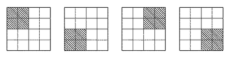
図6A,図6B,図6Cは、本実施形態の4パス印字において使用される3種類のマスクパターンをそれぞれ示した図である。マスクパターンにおける各格子は、1つのインクドットが記録される領域(1エリア)を示しており、ここでは、4×4の16エリアの領域におけるマスクパターン例が示されている。実際の記録の際には、この4×4マスのマスクパターンの組み合わせが、縦横ともに繰り返されて適用されるものと考えてよい。これらのマスクパターンはプリンタ102内の不図示のメモリに格納されており、マスクデータ変換部8において、該マスクパターンが実際の画像データに対して適用される。印刷データ生成部6においては、画素毎に、適用するマスクパターンを示す2ビットのID番号を選択し、印刷制御情報として印刷データに付加する。
FIGS. 6A, 6B, and 6C are diagrams respectively showing three types of mask patterns used in the 4-pass printing of the present embodiment. Each grid in the mask pattern indicates an area (one area) where one ink dot is recorded. Here, an example of a mask pattern in a 4 × 4 16 area area is shown. In actual recording, it may be considered that this combination of 4 × 4 mask patterns is repeatedly applied in both vertical and horizontal directions. These mask patterns are stored in a memory (not shown) in the
図6Aは、光沢性の高くなるインクの組み合わせに対して適用されるマスクパターン例を示し、以下、これらをマスクパターンaと称する。マスクパターンaとしては、1×1のエリアを単位領域として、各パスにおけるドットの分散性が高くなるように、第1〜第4のマスクパターンが設定されている。実際の印字走査においては、まず第1の記録走査にて、1パス目のマスクパターンに従って間引かれた記録データが記録され、続く第2、第3、および第4の記録走査で、それぞれのマスクパターンに従って間引かれた記録データが記録される。図6Aに示すように、1パス目〜4パス目でそれぞれ使用される第1〜第4のマスクパターンは、互いに補完の関係にあるため、記録媒体上の同一画像領域においては、4回の記録走査で画像データの全てが記録される。 FIG. 6A shows an example of a mask pattern applied to a combination of inks with high glossiness, and these are hereinafter referred to as a mask pattern a. As the mask pattern a, the first to fourth mask patterns are set so that the dispersibility of dots in each pass is high with a 1 × 1 area as a unit region. In the actual printing scan, first, the recording data thinned out according to the mask pattern of the first pass is recorded in the first recording scan, and in the subsequent second, third, and fourth recording scans, the respective recording data are recorded. The recording data thinned out according to the mask pattern is recorded. As shown in FIG. 6A, since the first to fourth mask patterns used in the first to fourth passes are complementary to each other, four times are used in the same image area on the recording medium. All of the image data is recorded by the recording scan.
図6Bは、平均的な光沢性となるインクの組み合わせに対して適用されるマスクパターン例を示し、以下、これらをマスクパターンbと称する。マスクパターンbは、各パスにおいて、2×1のエリアを単位領域とし、2つのドットが互いに隣接して記録される。 FIG. 6B shows an example of a mask pattern applied to a combination of inks having an average glossiness, and these are hereinafter referred to as a mask pattern b. The mask pattern b has a 2 × 1 area as a unit area in each pass, and two dots are recorded adjacent to each other.
図6Cは、光沢性の低くなるインクの組み合わせに対して適用されるマスクパターン例を示し、以下、これらをマスクパターンcと称する。マスクパターンcは、各パスにおいて、2×2のエリアを単位領域として、各パスにおけるドットの分散性が低くなるように、第1〜第4のマスクパターンが設定されており、したがって4つのドットが互いに隣接して記録される。 FIG. 6C shows an example of a mask pattern applied to a combination of inks with low glossiness, and these are hereinafter referred to as a mask pattern c. In the mask pattern c, the 1st to 4th mask patterns are set so that the dispersibility of dots in each pass becomes low with a 2 × 2 area as a unit region in each pass. Are recorded adjacent to each other.
図7Aおよび図7Bは、マスクパターンa,b,cを用いて記録媒体上に画像形成を行った場合における、インクの堆積状態を模式的に示す断面図である。図7Aは、マスクパターンaに従って、4パスのマルチパス記録を行った場合のインクの堆積状態を示し、図7Bは、マスクパターンcに従って、4パスのマルチパス記録を行った場合のインクの堆積状態をそれぞれ示している。図7Aおよび図7Bでは、1パス目の記録走査で記録されたドット〜4パス目の記録走査で記録されたドットを、図1と同様に1〜4で示している。図7Aおよび図7Bによれば、先行する記録走査で付与されたインクは記録媒体上で堆積しながらも、より下層に定着しており、適用するマスクパターンによって、記録媒体表面の平滑性に差が生じていることが分かる。 FIGS. 7A and 7B are cross-sectional views schematically showing the state of ink deposition when image formation is performed on a recording medium using mask patterns a, b, and c. FIG. 7A shows an ink deposition state when 4-pass multi-pass printing is performed according to the mask pattern a, and FIG. 7B shows ink deposition when 4-pass multi-pass printing is performed according to the mask pattern c. Each state is shown. In FIG. 7A and FIG. 7B, dots printed by the first pass printing scan to dots printed by the fourth pass printing scan are denoted by 1 to 4 as in FIG. 1. According to FIGS. 7A and 7B, the ink applied in the preceding recording scan is deposited on the lower layer while being deposited on the recording medium, and there is a difference in the smoothness of the surface of the recording medium depending on the mask pattern to be applied. It can be seen that
このように、インクの組み合わせの光沢特性に応じてマスクパターンを選択することによって、対象となる画素の平滑性を変化させ、光沢性を制御することが可能となる。 Thus, by selecting the mask pattern according to the gloss characteristics of the ink combination, it is possible to change the smoothness of the target pixel and control the gloss.
以下、本実施形態におけるマスクパターンの選択処理について、図8のフローチャートを用いて詳細に説明する。 Hereinafter, the mask pattern selection processing in the present embodiment will be described in detail with reference to the flowchart of FIG.
本実施形態においては予め、光沢特性値が128に対応する画素をマスクパターンbを用いて記録し、その結果として得られた該画素の光沢度を、目標光沢値として設定しておく。 In this embodiment, pixels corresponding to a gloss characteristic value of 128 are recorded in advance using the mask pattern b, and the glossiness of the pixels obtained as a result is set as a target gloss value.
そして、記録対象となる画素について、色分解部3により得られた光沢特性値を取得し(S801)、その値を目標光沢値と比較する(S802)。該比較の結果、光沢特性値が目標光沢値よりも高い場合は、マスクパターンaを用いるべくステップS803へ進み、光沢特性値が目標光沢値よりも低い場合は、マスクパターンcを用いるべくステップS804へ進む。
Then, the gloss characteristic value obtained by the
ここで本実施形態においては、記録対象となる画像領域の光沢特性値に応じて複数のマスクパターンを混在させることにより、記録後の光沢度が目標光沢値に近づくように調整する。そこでステップS803では、周辺の画素と併せ、例えば誤差拡散法を用いてマスクパターンaとマスクパターンbを光沢特性値に応じた割合で混合して配置する(S805,S806)。なお、この混合配置方法としては誤差拡散法に限らず、例えばディザ法等の他の方法を用いてマスクパターンを組み合わせてもよい。 Here, in the present embodiment, a plurality of mask patterns are mixed according to the gloss characteristic value of the image area to be recorded, thereby adjusting the gloss level after recording to the target gloss value. In step S803, the mask pattern a and the mask pattern b are mixed and arranged at a ratio corresponding to the gloss characteristic value by using, for example, an error diffusion method together with the surrounding pixels (S805 and S806). Note that the mixed arrangement method is not limited to the error diffusion method, and the mask pattern may be combined by using another method such as a dither method.
同様にステップS804においても、周辺の画素と併せ、例えば誤差拡散法を用いてマスクパターンbとマスクパターンcを光沢特性値に応じた割合で混合して配置する(S806,S807)。 Similarly, in step S804, together with the surrounding pixels, the mask pattern b and the mask pattern c are mixed and arranged at a ratio corresponding to the gloss characteristic value using, for example, an error diffusion method (S806, S807).
なお、ステップS802の比較において光沢特性値が目標光沢値に等しい場合は、マスクパターンbのみを用いるべくステップS806へ進む。 If the gloss characteristic value is equal to the target gloss value in the comparison in step S802, the process proceeds to step S806 to use only the mask pattern b.
本実施形態では以上のように、光沢特性値に応じたマスクパターンを選択して配置することにより、目標光沢値を実現する。 In the present embodiment, as described above, the target gloss value is realized by selecting and arranging the mask pattern corresponding to the gloss characteristic value.
なお本実施形態においては、光沢特性値が高い画像領域については、単色での光沢性が相対的に高いCインクのみならず、光沢性が低いKインクや平均的な光沢性をもつM,Yインクについても、マスクパターンaを適用して記録を行う。同様に、光沢特性値が低い画像領域についても、単体での光沢特性にかかわらず全てのインクについて、マスクパターンcを適用する。または、光沢特性値が高い画像領域については、光沢性が相対的に高い例えばCインクのみにマスクパターンaを適用し、反対に光沢特性値が低い画像領域については、光沢性が相対的に低い例えばKインクのみにマスクパターンcを適用するようにしても良い。 In the present embodiment, for an image area having a high gloss characteristic value, not only C ink having a relatively high glossiness in a single color, but also K ink having a low glossiness or M, Y having an average glossiness. The ink is also recorded by applying the mask pattern a. Similarly, the mask pattern c is applied to all inks in an image region having a low gloss characteristic value regardless of the single gloss characteristic. Alternatively, for an image region having a high gloss characteristic value, the mask pattern a is applied only to C ink, for example, which has a relatively high gloss property. On the other hand, for an image region having a low gloss property value, the gloss property is relatively low. For example, the mask pattern c may be applied only to K ink.
また、記録媒体としてマット紙が選択された場合には、特に記録部の光沢感に関する問題は発生しないと考えられるため、本実施形態では全ての画素について従来と同様に、分散性に富んだマスクパターンaを適用する。 In addition, when mat paper is selected as the recording medium, it is considered that there is no problem with the glossiness of the recording portion. Therefore, in this embodiment, a mask with high dispersibility is used for all pixels as in the conventional case. Apply pattern a.
なお、本実施形態では3種類のマスクパターンの組み合わせを用いる例を示したが、より多くの種類のマスクパターンを組み合わせても良いし、2種類のマスクパターンの組み合わせのみを用いても良い。すなわち、画像領域内の光沢性の制御が可能であれば、マスクパターンの種類はいくつであっても良い。 In this embodiment, an example of using a combination of three types of mask patterns has been described. However, a larger number of types of mask patterns may be combined, or only a combination of two types of mask patterns may be used. That is, any number of types of mask patterns may be used as long as glossiness in the image area can be controlled.
以上説明したように本実施形態によれば、各画素においてインクの組み合わせに応じた光沢特性に基づいて、各パスにおけるドットの分散性を変化させたマスクパターンを選択して適用する。これにより、記録媒体表面における、インクの堆積に伴う平滑性を制御することができ、画像内の光沢度を均一化して光沢ムラを抑制し、好適な光沢感を実現することが可能となる。 As described above, according to the present embodiment, a mask pattern in which the dispersibility of dots in each pass is changed is selected and applied based on the gloss characteristics corresponding to the ink combination in each pixel. This makes it possible to control the smoothness associated with the ink deposition on the surface of the recording medium, uniformizing the glossiness in the image, suppressing gloss unevenness, and realizing a suitable glossiness.
<他の実施形態>
以上、実施形態例を詳述したが、本発明は例えば、システム、装置、方法、プログラム若しくは記憶媒体(記録媒体)等としての実施態様をとることが可能である。具体的には、複数の機器(例えば、ホストコンピュータ、インタフェース機器、撮像装置、webアプリケーション等)から構成されるシステムに適用しても良いし、また、一つの機器からなる装置に適用しても良い。
<Other embodiments>
Although the embodiment has been described in detail above, the present invention can take an embodiment as a system, apparatus, method, program, storage medium (recording medium), or the like. Specifically, the present invention may be applied to a system composed of a plurality of devices (for example, a host computer, an interface device, an imaging device, a web application, etc.), or may be applied to a device composed of a single device. good.
尚本発明は、前述した実施形態の機能を実現するソフトウェアのプログラムを、システムあるいは装置に直接あるいは遠隔から供給し、そのシステムあるいは装置のコンピュータが該供給されたプログラムコードを読み出して実行することによっても達成される。なお、この場合のプログラムとは、実施形態において図に示したフローチャートに対応したプログラムである。 In the present invention, a software program for realizing the functions of the above-described embodiments is supplied directly or remotely to a system or apparatus, and the computer of the system or apparatus reads and executes the supplied program code. Is also achieved. The program in this case is a program corresponding to the flowchart shown in the drawing in the embodiment.
従って、本発明の機能処理をコンピュータで実現するために、該コンピュータにインストールされるプログラムコード自体も本発明を実現するものである。つまり、本発明は、本発明の機能処理を実現するためのコンピュータプログラム自体も含まれる。 Accordingly, since the functions of the present invention are implemented by computer, the program code installed in the computer also implements the present invention. In other words, the present invention includes a computer program itself for realizing the functional processing of the present invention.
その場合、プログラムの機能を有していれば、オブジェクトコード、インタプリタにより実行されるプログラム、OSに供給するスクリプトデータ等の形態であっても良い。 In this case, as long as it has a program function, it may be in the form of object code, a program executed by an interpreter, script data supplied to the OS, or the like.
プログラムを供給するための記録媒体としては、以下に示す媒体がある。例えば、フロッピー(登録商標)ディスク、ハードディスク、光ディスク、光磁気ディスク、MO、CD-ROM、CD-R、CD-RW、磁気テープ、不揮発性のメモリカード、ROM、DVD(DVD-ROM,DVD-R)などである。 Recording media for supplying the program include the following media. For example, floppy disk, hard disk, optical disk, magneto-optical disk, MO, CD-ROM, CD-R, CD-RW, magnetic tape, nonvolatile memory card, ROM, DVD (DVD-ROM, DVD- R).
プログラムの供給方法としては、以下に示す方法も可能である。すなわち、クライアントコンピュータのブラウザからインターネットのホームページに接続し、そこから本発明のコンピュータプログラムそのもの(又は圧縮され自動インストール機能を含むファイル)をハードディスク等の記録媒体にダウンロードする。また、本発明のプログラムを構成するプログラムコードを複数のファイルに分割し、それぞれのファイルを異なるホームページからダウンロードすることによっても実現可能である。つまり、本発明の機能処理をコンピュータで実現するためのプログラムファイルを複数のユーザに対してダウンロードさせるWWWサーバも、本発明に含まれるものである。 As a program supply method, the following method is also possible. That is, the browser of the client computer is connected to a homepage on the Internet, and the computer program itself (or a compressed file including an automatic installation function) of the present invention is downloaded to a recording medium such as a hard disk. It can also be realized by dividing the program code constituting the program of the present invention into a plurality of files and downloading each file from a different homepage. That is, a WWW server that allows a plurality of users to download a program file for realizing the functional processing of the present invention on a computer is also included in the present invention.
また、本発明のプログラムを暗号化してCD-ROM等の記憶媒体に格納してユーザに配布し、所定の条件をクリアしたユーザに対し、インターネットを介してホームページから暗号化を解く鍵情報をダウンロードさせることも可能である。すなわち該ユーザは、その鍵情報を使用することによって暗号化されたプログラムを実行し、コンピュータにインストールさせることができる。 In addition, the program of the present invention is encrypted, stored in a storage medium such as a CD-ROM, distributed to users, and key information for decryption is downloaded from a homepage via the Internet to users who have cleared predetermined conditions. It is also possible to make it. That is, the user can execute the encrypted program by using the key information and install it on the computer.
また、コンピュータが、読み出したプログラムを実行することによって、前述した実施形態の機能が実現される。さらに、そのプログラムの指示に基づき、コンピュータ上で稼動しているOSなどが、実際の処理の一部または全部を行い、その処理によっても前述した実施形態の機能が実現され得る。 Further, the functions of the above-described embodiments are realized by the computer executing the read program. Furthermore, based on the instructions of the program, an OS or the like running on the computer performs part or all of the actual processing, and the functions of the above-described embodiments can also be realized by the processing.
さらに、記録媒体から読み出されたプログラムが、コンピュータに挿入された機能拡張ボードやコンピュータに接続された機能拡張ユニットに備わるメモリに書き込まれた後、実行されることによっても、前述した実施形態の機能が実現される。すなわち、該プログラムの指示に基づき、その機能拡張ボードや機能拡張ユニットに備わるCPUなどが実際の処理の一部または全部を行うことが可能である。 Further, the program read from the recording medium is written in a memory provided in a function expansion board inserted into the computer or a function expansion unit connected to the computer, and then executed, so that the program of the above-described embodiment can be obtained. Function is realized. That is, based on the instructions of the program, the CPU provided in the function expansion board or function expansion unit can perform part or all of the actual processing.
Claims (8)
前記記録対象領域で用いるインクの使用量に応じて決まる光沢度を取得する取得手段と、
前記記録対象領域に対して前記複数回の記録走査で記録するドットパターンから、それぞれの記録走査で記録するドットを、前記光沢度に基づいて決定する決定手段と、
記録走査毎に前記決定手段が決定したドットを、該記録走査によって前記記録対象領域に記録する記録手段とを備え、
前記光沢度が第1の光沢度である場合に前記決定手段が記録走査毎に決定したドットの分散度合いは、前記光沢度が前記第1の光沢度よりも低い第2の光沢度である場合に前記決定手段が記録走査毎に決定したドットの分散度合いよりも大きい
ことを特徴とする画像形成装置。 An image forming apparatus that performs a plurality of recording scans on the same recording target area using an ink containing a pigment,
Acquisition means for acquiring a glossiness determined according to the amount of ink used in the recording target area;
A determination unit that determines, based on the glossiness, a dot to be recorded in each recording scan from a dot pattern to be recorded in the recording target region by the plurality of recording scans;
A recording means for recording the dots determined by the determination means for each recording scan in the recording target area by the recording scanning;
When the glossiness is the first glossiness, the degree of dot dispersion determined by the determination unit for each printing scan is the second glossiness that is lower than the first glossiness. In addition, the image forming apparatus is characterized in that it is larger than the degree of dot dispersion determined for each recording scan by the determining means.
前記光沢度と予め設定された閾値との大小比較を行い、該大小比較の結果に応じて、前記ドットパターンを構成するそれぞれのドットを記録ドットとするか非記録ドットとするかを規定するマスクパターンを、それぞれの記録走査に対して決定し、
前記記録手段は、記録走査毎に前記決定したマスクパターンが規定する記録ドットを、該記録走査によって前記記録対象領域に記録し、
前記光沢度が前記閾値より高い場合に前記決定したマスクパターンが規定する記録ドットの分散度合いは、前記光沢度が前記閾値より低い場合に前記決定したマスクパターンが規定する記録ドットの分散度合いよりも大きい
ことを特徴とする請求項1に記載の画像形成装置。 The determining means includes
A mask that compares the gloss level with a preset threshold value and defines whether each dot constituting the dot pattern is a recording dot or a non-recording dot according to a result of the size comparison A pattern is determined for each recording scan,
The recording means records the recording dots defined by the determined mask pattern for each recording scan in the recording target area by the recording scanning,
When the glossiness is higher than the threshold, the dispersion degree of the recording dots defined by the determined mask pattern is greater than the dispersion degree of the recording dots defined by the determined mask pattern when the glossiness is lower than the threshold. The image forming apparatus according to claim 1, wherein the image forming apparatus is large.
前記記録ドットの分散の度合いが同じで、互いに補完の関係にある複数のマスクパターンの組を、該度合いが異なる組毎に格納するマスクパターン格納手段を備え、
前記決定手段は、前記大小比較の結果に応じた組を前記マスクパターン格納手段から選択し、選択した組内のマスクパターンを、前記記録走査毎に切替えて用い、
前記光沢度が前記閾値より高い場合に前記マスクパターン格納手段から選択した組を高分散組とし、前記光沢度が前記閾値より低い場合に前記マスクパターン格納手段から選択した組を低分散組とした場合に、前記高分散組内のマスクパターンが規定する記録ドットの分散の度合いは、前記低分散組内のマスクパターンが規定する記録ドットの分散の度合いよりも大きい
ことを特徴とする請求項2に記載の画像形成装置。 Furthermore,
A mask pattern storage means for storing a set of a plurality of mask patterns having the same degree of dispersion of the recording dots and complementary to each other for each set having different degrees,
The determining means selects a set according to the result of the size comparison from the mask pattern storage means, and uses the mask pattern in the selected set by switching for each recording scan,
A set selected from the mask pattern storage means when the glossiness is higher than the threshold is a high dispersion set, and a set selected from the mask pattern storage means is a low dispersion set when the glossiness is lower than the threshold. In this case, the degree of dispersion of the recording dots defined by the mask pattern in the high dispersion group is greater than the degree of dispersion of the recording dots defined by the mask pattern in the low dispersion group. The image forming apparatus described in 1.
前記決定手段は、前記光沢度が前記閾値より高い場合には、前記高分散組と前記中間分散組と、を選択し、選択したそれぞれの組から選択したマスクパターンを混在させ、該混在させたマスクパターンを、前記記録対象領域用のマスクパターンとして決定し、
前記決定手段は、前記光沢度が前記閾値より低い場合には、前記低分散組と前記中間分散組と、を選択し、選択したそれぞれの組から選択したマスクパターンを混在させ、該混在させたマスクパターンを、前記記録対象領域用のマスクパターンとして決定する
ことを特徴とする請求項3に記載の画像形成装置。 The mask pattern storage means is configured such that the degree of dispersion of the recording dots defined by the mask pattern in the intermediate dispersion group is the degree of dispersion of the recording dots defined by the mask pattern in the high dispersion group and the mask in the low dispersion group. Storing the intermediate dispersion group, the high dispersion group, and the low dispersion group, which are intermediate to the degree of dispersion of the recording dots defined by the pattern;
When the glossiness is higher than the threshold value, the determination unit selects the high dispersion group and the intermediate dispersion group, and mixes the mask patterns selected from the selected groups. A mask pattern is determined as a mask pattern for the recording target area,
When the glossiness is lower than the threshold, the determining unit selects the low dispersion group and the intermediate dispersion group, mixes the mask patterns selected from the selected groups, and mixes the mask patterns. The image forming apparatus according to claim 3, wherein a mask pattern is determined as a mask pattern for the recording target area.
前記記録対象領域で用いるインクの使用量に応じて決まる光沢度を取得する取得工程と、
前記記録対象領域に対して前記複数回の記録走査で記録するドットパターンから、それぞれの記録走査で記録するドットを、前記光沢度に基づいて決定する決定工程と、
記録走査毎に前記決定工程で決定したドットを、該記録走査によって前記記録対象領域に記録する記録工程とを備え、
前記光沢度が第1の光沢度である場合に前記決定工程で記録走査毎に決定したドットの分散度合いは、前記光沢度が前記第1の光沢度よりも低い第2の光沢度である場合に前記決定工程で記録走査毎に決定したドットの分散度合いよりも大きい
ことを特徴とする画像形成装置の制御方法。 A method for controlling an image forming apparatus that performs a plurality of recording scans on the same recording target area using ink containing a pigment,
An acquisition step of acquiring a glossiness determined according to the amount of ink used in the recording target area;
A determination step of determining dots to be recorded in each recording scan from the dot pattern to be recorded by the plurality of recording scans with respect to the recording target area, based on the glossiness;
A recording step of recording the dots determined in the determination step for each recording scan in the recording target area by the recording scan,
When the glossiness is the first glossiness, the degree of dot dispersion determined for each recording scan in the determination step is the second glossiness that is lower than the first glossiness. And a degree of dot dispersion determined for each recording scan in the determination step.
Priority Applications (4)
| Application Number | Priority Date | Filing Date | Title |
|---|---|---|---|
| JP2006353179A JP4838704B2 (en) | 2006-12-27 | 2006-12-27 | Image forming apparatus and control method thereof |
| US11/947,014 US7914102B2 (en) | 2006-12-27 | 2007-11-29 | Image forming apparatus and control method thereof |
| CN2007103060061A CN101209630B (en) | 2006-12-27 | 2007-12-27 | Image forming apparatus and control method thereof |
| US13/033,869 US8272712B2 (en) | 2006-12-27 | 2011-02-24 | Image forming apparatus and control method thereof |
Applications Claiming Priority (1)
| Application Number | Priority Date | Filing Date | Title |
|---|---|---|---|
| JP2006353179A JP4838704B2 (en) | 2006-12-27 | 2006-12-27 | Image forming apparatus and control method thereof |
Publications (3)
| Publication Number | Publication Date |
|---|---|
| JP2008162095A JP2008162095A (en) | 2008-07-17 |
| JP2008162095A5 JP2008162095A5 (en) | 2010-02-12 |
| JP4838704B2 true JP4838704B2 (en) | 2011-12-14 |
Family
ID=39583266
Family Applications (1)
| Application Number | Title | Priority Date | Filing Date |
|---|---|---|---|
| JP2006353179A Expired - Fee Related JP4838704B2 (en) | 2006-12-27 | 2006-12-27 | Image forming apparatus and control method thereof |
Country Status (3)
| Country | Link |
|---|---|
| US (2) | US7914102B2 (en) |
| JP (1) | JP4838704B2 (en) |
| CN (1) | CN101209630B (en) |
Families Citing this family (22)
| Publication number | Priority date | Publication date | Assignee | Title |
|---|---|---|---|---|
| US7948652B2 (en) | 2006-04-11 | 2011-05-24 | Canon Kabushiki Kaisha | Processor, method, and program for processing data using a mask pattern to print dots in each area in a non-periodic arrangement by using an integral multiple of the areas |
| JP4838704B2 (en) * | 2006-12-27 | 2011-12-14 | キヤノン株式会社 | Image forming apparatus and control method thereof |
| JP2008213280A (en) * | 2007-03-02 | 2008-09-18 | Seiren Co Ltd | Method for manufacturing colored material |
| JP5311980B2 (en) | 2008-11-20 | 2013-10-09 | キヤノン株式会社 | Inkjet recording device |
| JP5164826B2 (en) * | 2008-12-25 | 2013-03-21 | キヤノン株式会社 | Image processing apparatus and image processing method |
| JP5473420B2 (en) * | 2009-06-15 | 2014-04-16 | キヤノン株式会社 | DATA GENERATION DEVICE, INKJET RECORDING DEVICE, PROGRAM, AND DATA GENERATION METHOD |
| JP5723125B2 (en) * | 2009-10-19 | 2015-05-27 | キヤノン株式会社 | Image processing apparatus, image processing method, and program |
| JP5586937B2 (en) | 2009-12-18 | 2014-09-10 | キヤノン株式会社 | Inkjet recording apparatus, inkjet recording method and program |
| JP5631041B2 (en) * | 2010-04-02 | 2014-11-26 | キヤノン株式会社 | Color processing apparatus, color processing method, and image forming apparatus |
| JP5733928B2 (en) | 2010-08-11 | 2015-06-10 | キヤノン株式会社 | Image recording apparatus, image recording method, and program |
| JP5616719B2 (en) * | 2010-08-25 | 2014-10-29 | キヤノン株式会社 | Image forming apparatus and image forming method |
| JP5539122B2 (en) * | 2010-08-31 | 2014-07-02 | キヤノン株式会社 | Image processing method and image processing apparatus |
| JP5750922B2 (en) * | 2011-02-10 | 2015-07-22 | 株式会社リコー | Image processing apparatus and image processing method |
| JP6004732B2 (en) * | 2011-05-02 | 2016-10-12 | キヤノン株式会社 | Data processing apparatus and data processing method |
| JP2013230586A (en) * | 2012-04-27 | 2013-11-14 | Seiko Epson Corp | Print data generation device, printing method, and program |
| JP6047927B2 (en) * | 2012-05-25 | 2016-12-21 | セイコーエプソン株式会社 | Droplet ejecting apparatus and printing method |
| JP5677383B2 (en) | 2012-08-21 | 2015-02-25 | 富士フイルム株式会社 | Image forming apparatus and image forming method |
| JP5998928B2 (en) * | 2012-12-28 | 2016-09-28 | ブラザー工業株式会社 | Image processing apparatus and control program for image processing apparatus |
| US8801139B2 (en) * | 2012-12-31 | 2014-08-12 | Funai Electric Co., Ltd. | Sequential scan method for determining ink drying time in an inkjet printer |
| JP6253243B2 (en) | 2013-04-16 | 2017-12-27 | キヤノン株式会社 | Recording apparatus and recording method |
| JP6355419B2 (en) * | 2014-05-14 | 2018-07-11 | キヤノン株式会社 | Image processing apparatus and image processing method |
| CN115157684B (en) * | 2022-07-21 | 2024-05-28 | 中山市嘉宝日用制品有限公司 | 3D printing process of PC product |
Family Cites Families (11)
| Publication number | Priority date | Publication date | Assignee | Title |
|---|---|---|---|---|
| JP2001200183A (en) | 2000-01-18 | 2001-07-24 | Fujikura Kasei Co Ltd | Ink for ink jet and method for fixing the ink |
| JP2001323192A (en) | 2000-05-17 | 2001-11-20 | Konica Corp | Inkjet water-based pigment ink and ink-jet recording method |
| US6877850B2 (en) * | 2001-04-24 | 2005-04-12 | Seiko Epson Corporation | Ink jet recording method, ink set, and recorded matter using them |
| NL1018114C2 (en) * | 2001-05-21 | 2002-11-25 | Oce Tech Bv | Inkjet printer and a method for printing on a receiving material. |
| JP4261980B2 (en) * | 2003-05-16 | 2009-05-13 | キヤノン株式会社 | Image forming method |
| US7258412B2 (en) * | 2003-08-11 | 2007-08-21 | Canon Kabushiki Kaisha | Ink-jet printing method, apparatus and system |
| US7168776B2 (en) * | 2003-10-24 | 2007-01-30 | Seiko Epson Corporation | Printing apparatus, computer-readable storage medium, printing system, and printing method |
| JP4383944B2 (en) * | 2004-04-06 | 2009-12-16 | キヤノン株式会社 | Inkjet recording apparatus and inkjet recording method |
| JP2006027193A (en) * | 2004-07-21 | 2006-02-02 | Konica Minolta Holdings Inc | Inkjet recording method and device |
| JP4669249B2 (en) * | 2004-08-30 | 2011-04-13 | キヤノン株式会社 | Inkjet recording method, inkjet recording system, and inkjet recording apparatus |
| JP4838704B2 (en) * | 2006-12-27 | 2011-12-14 | キヤノン株式会社 | Image forming apparatus and control method thereof |
-
2006
- 2006-12-27 JP JP2006353179A patent/JP4838704B2/en not_active Expired - Fee Related
-
2007
- 2007-11-29 US US11/947,014 patent/US7914102B2/en not_active Expired - Fee Related
- 2007-12-27 CN CN2007103060061A patent/CN101209630B/en not_active Expired - Fee Related
-
2011
- 2011-02-24 US US13/033,869 patent/US8272712B2/en not_active Expired - Fee Related
Also Published As
| Publication number | Publication date |
|---|---|
| US7914102B2 (en) | 2011-03-29 |
| JP2008162095A (en) | 2008-07-17 |
| US20110141185A1 (en) | 2011-06-16 |
| CN101209630A (en) | 2008-07-02 |
| US8272712B2 (en) | 2012-09-25 |
| US20080158280A1 (en) | 2008-07-03 |
| CN101209630B (en) | 2011-04-20 |
Similar Documents
| Publication | Publication Date | Title |
|---|---|---|
| JP4838704B2 (en) | Image forming apparatus and control method thereof | |
| US8314971B2 (en) | Apparatus and method for image processing | |
| JP5395361B2 (en) | Information processing method and information processing apparatus | |
| JP5014475B2 (en) | Image processing apparatus and image processing method | |
| JP2012171325A (en) | Color processing device and color processing method | |
| JP5634154B2 (en) | Image processing apparatus and image processing method | |
| JP5616719B2 (en) | Image forming apparatus and image forming method | |
| US20080158281A1 (en) | Image forming apparatus and control method thereof | |
| JP6755739B2 (en) | Image processing equipment, image processing methods and programs | |
| JP2010100017A (en) | Image processor, control method therefor, and program | |
| CN102673194B (en) | Printing control apparatus and printing control method | |
| JP4484505B2 (en) | Inkjet recording system, determination apparatus and program | |
| JP4189679B2 (en) | Print control apparatus, print control method, and print control program | |
| JP2005280276A (en) | Ink-jet recording method and ink-jet recording system | |
| JP2012039320A (en) | Image processing system and image processing method | |
| JP5632681B2 (en) | Control apparatus and method | |
| JP2012049722A (en) | Image formation device and image formation method | |
| JP2021125845A (en) | Image processing device, image processing method, and program | |
| JP5697425B2 (en) | Image processing apparatus and image processing method | |
| JP5733932B2 (en) | Color processing apparatus and color processing method | |
| JP4991503B2 (en) | Image processing apparatus and image processing method | |
| JP2010094895A (en) | Image forming device, image forming method, and program | |
| JP2003320691A (en) | Method for diffusing multi-level color error by providing reduced sensitivity to printing process fluctuation error |
Legal Events
| Date | Code | Title | Description |
|---|---|---|---|
| A521 | Written amendment |
Free format text: JAPANESE INTERMEDIATE CODE: A523 Effective date: 20091214 |
|
| A621 | Written request for application examination |
Free format text: JAPANESE INTERMEDIATE CODE: A621 Effective date: 20091214 |
|
| A977 | Report on retrieval |
Free format text: JAPANESE INTERMEDIATE CODE: A971007 Effective date: 20110920 |
|
| TRDD | Decision of grant or rejection written | ||
| A01 | Written decision to grant a patent or to grant a registration (utility model) |
Free format text: JAPANESE INTERMEDIATE CODE: A01 Effective date: 20110926 |
|
| A01 | Written decision to grant a patent or to grant a registration (utility model) |
Free format text: JAPANESE INTERMEDIATE CODE: A01 |
|
| A61 | First payment of annual fees (during grant procedure) |
Free format text: JAPANESE INTERMEDIATE CODE: A61 Effective date: 20110930 |
|
| FPAY | Renewal fee payment (event date is renewal date of database) |
Free format text: PAYMENT UNTIL: 20141007 Year of fee payment: 3 |
|
| FPAY | Renewal fee payment (event date is renewal date of database) |
Free format text: PAYMENT UNTIL: 20141007 Year of fee payment: 3 |
|
| LAPS | Cancellation because of no payment of annual fees |