JP4837397B2 - Support member for blade display - Google Patents
Support member for blade display Download PDFInfo
- Publication number
- JP4837397B2 JP4837397B2 JP2006053244A JP2006053244A JP4837397B2 JP 4837397 B2 JP4837397 B2 JP 4837397B2 JP 2006053244 A JP2006053244 A JP 2006053244A JP 2006053244 A JP2006053244 A JP 2006053244A JP 4837397 B2 JP4837397 B2 JP 4837397B2
- Authority
- JP
- Japan
- Prior art keywords
- sheet
- blade
- opening
- tongue
- sides
- Prior art date
- Legal status (The legal status is an assumption and is not a legal conclusion. Google has not performed a legal analysis and makes no representation as to the accuracy of the status listed.)
- Expired - Fee Related
Links
Images


Classifications
-
- B—PERFORMING OPERATIONS; TRANSPORTING
- B26—HAND CUTTING TOOLS; CUTTING; SEVERING
- B26B—HAND-HELD CUTTING TOOLS NOT OTHERWISE PROVIDED FOR
- B26B29/00—Guards or sheaths or guides for hand cutting tools; Arrangements for guiding hand cutting tools
- B26B29/04—Guards or sheaths for scissors, e.g. combined with manicuring appliances
-
- A—HUMAN NECESSITIES
- A47—FURNITURE; DOMESTIC ARTICLES OR APPLIANCES; COFFEE MILLS; SPICE MILLS; SUCTION CLEANERS IN GENERAL
- A47F—SPECIAL FURNITURE, FITTINGS, OR ACCESSORIES FOR SHOPS, STOREHOUSES, BARS, RESTAURANTS OR THE LIKE; PAYING COUNTERS
- A47F5/00—Show stands, hangers, or shelves characterised by their constructional features
- A47F5/0006—Hangers for hanging articles on bars, tringles, bracket arms or the like
-
- A—HUMAN NECESSITIES
- A47—FURNITURE; DOMESTIC ARTICLES OR APPLIANCES; COFFEE MILLS; SPICE MILLS; SUCTION CLEANERS IN GENERAL
- A47F—SPECIAL FURNITURE, FITTINGS, OR ACCESSORIES FOR SHOPS, STOREHOUSES, BARS, RESTAURANTS OR THE LIKE; PAYING COUNTERS
- A47F7/00—Show stands, hangers, or shelves, adapted for particular articles or materials
- A47F7/0021—Show stands, hangers, or shelves, adapted for particular articles or materials for long or non-stable articles, e.g. fishing rods, pencils, lipsticks or the like; Compartments or recesses as stabilising means
- A47F7/0028—Show stands, hangers, or shelves, adapted for particular articles or materials for long or non-stable articles, e.g. fishing rods, pencils, lipsticks or the like; Compartments or recesses as stabilising means with one compartment or recess for each article
-
- B—PERFORMING OPERATIONS; TRANSPORTING
- B65—CONVEYING; PACKING; STORING; HANDLING THIN OR FILAMENTARY MATERIAL
- B65D—CONTAINERS FOR STORAGE OR TRANSPORT OF ARTICLES OR MATERIALS, e.g. BAGS, BARRELS, BOTTLES, BOXES, CANS, CARTONS, CRATES, DRUMS, JARS, TANKS, HOPPERS, FORWARDING CONTAINERS; ACCESSORIES, CLOSURES, OR FITTINGS THEREFOR; PACKAGING ELEMENTS; PACKAGES
- B65D73/00—Packages comprising articles attached to cards, sheets or webs
- B65D73/0007—Packages comprising articles attached to cards, sheets or webs the articles being attached to the plane surface of a single card
- B65D73/0014—Packages comprising articles attached to cards, sheets or webs the articles being attached to the plane surface of a single card by means of separate fixing elements, e.g. clips, clamps, bands
Description
本発明は、鋏などの刃物を陳列するために支持する支持部材に関するものである。 The present invention relates to a support member that supports a blade such as a bag for display.
下記特許文献1では、台紙(1,22,33,39,47,60,68)上に洋鋏(14)が架橋部(7,26,35,41)や止めひも(11,29,57,67,77)や止め紙(37)などを利用して開閉操作可能に支持されている。しかし、台紙(1,22,33,39,47,60,68)上で洋鋏(14)の刃部(18,19)を不用意に触れるおそれがあった。
In the following
そこで、上記特許文献1の問題点を改良すべくなされた下記特許文献2において、同公報の図7〜9に示す第3実施形態や図10〜11に示す第4実施形態では、台シート(15)とカバーシート(16)とが互いに重ねられ、その台シート(15)の下端縁とカバーシート(16)の下端縁との間に設けられた挿入口部(30)から西洋鋏(6)の両刃部(10)が挿入されて支持室(24)に収容されている。
しかし、上記特許文献2では、西洋鋏(6)の両柄部(11)が不用意に振れると、台シート(15)とカバーシート(16)とが両柄部(11)に面する部分で互いに押し広げられるおそれがあるため、台シート(15)とカバーシート(16)と西洋鋏(6)とを止め索(37)により結んで確実に位置決めする必要がある。
However, in the above-mentioned
この発明は、鋏などの刃物の刃部を重合シート(例えば前記台シート15とカバーシート16に該当)により覆うばかりではなく、前記挿入口部(30)に該当する開口を設ける位置を改良して鋏などの刃物の柄部をシートの押さえとして有効に利用することにより、重合シートの分離を規制することを目的としている。
The present invention not only covers the blade portion of a blade such as a ridge with a superposed sheet (for example, corresponding to the
後記実施形態の図面(図1〜3に示す第1実施形態、図4〜5に示す第2実施形態)の符号を援用して本発明を説明する。
* 請求項1の発明
請求項1の発明にかかる刃物陳列用支持部材は、下記のように構成されている。
The present invention will be described with reference to the drawings of the following embodiments (the first embodiment shown in FIGS. 1 to 3 and the second embodiment shown in FIGS. 4 to 5).
* Invention of
第一シート1と第二シート11とを互いに重ねた支持体20を備えている。この第二シート11にはその外周縁部11a,11b,11c,11dの内側に開口16を設けている。その開口16からこの第一シート1と第二シート11との間の収容室23に刃物24の刃部27を挿入して第一シート1及び第二シート11により覆うとともに、この収容室23の開口16から露出する刃物24の柄部28を第二シート11の外側に重ねている。この刃物24を支持体20に保持する止め手段7,16,29を設けている。
A
従って、第一シート1と第二シート11との間の収容室23に刃物24の刃部27を第二シート11の開口16から収容して覆った際、第二シート11が第一シート1に対し刃物24の柄部28により押さえ付けられるため、第一シート1に対する第二シート11の分離を規制することができる。
Accordingly, when the
また、支持体20において、第一シート1と第二シート11とは互いに分離されて設けられ、この第一シート1と第二シート11とを互いに保持する結合手段21,22を設けている。
従って、第一シート1及び第二シート11の材質や形態や加工などについて互いに異なる任意のものを選択する際にその選択の自由度を増すことができる。
Further, the
Accordingly, the degree of freedom of selection can be increased when selecting different materials, forms, processing, and the like of the
前記結合手段は、開口16に対し刃部27を挿入する方向Zの両側のうち、その刃部27の挿入向きZU側でその挿入方向Zに対し直交する方向Yの両側にそれぞれ設けられた第一連結部21と、その挿入向きZUに対する反対側で設けられた第二連結部22とを備えている。前記両側の第一連結部21は、第一シート1と第二シート11とのうち、一方のシート1に設けた切込み5,6と、他方のシート11に設けた舌片14,15とを有し、この切込み5,6にこの舌片14,15を挿入したものである。前記両側の第一連結部21では、前記第二連結部22により第一シート1と第二シート11とを互いに位置決めした状態で、第一シート1と第二シート11とを相対動させて切込み5,6に対し舌片14,15を挿脱し得る挿脱可能状態と、舌片14,15が切込み5,6に挿入された挿脱可能状態で第一シート1と第二シート11との相対動により舌片14,15に設けた係止部14b,15bが切込み5,6の係止部5a,6aに係止されて舌片14,15が切込み5,6から離脱するのを阻止する係止状態とを取る。例えば、第二連結部22は挿入方向Zに対し直交する方向Yの両側にそれぞれ設けられ、第一シート1と第二シート11とのうち、一方のシート1に設けた切込み8,9と、他方のシート11に設けた舌片17,18とを有し、この切込み8,9にこの舌片17,18を挿入したものである。
従って、第一シート1と第二シート11とを簡単な構造の結合手段21,22により容易に連結することができる。
The coupling means is provided on both sides in the direction Z in which the
Therefore, the 1st sheet |
* 請求項2の発明
請求項1の発明を前提とする請求項2の発明においては、前記両側の第一連結部21のうち、一方の第一連結部21の切込み5の係止部5aと他方の第一連結部21の切込み6の係止部6aとの間の間隔Aを、一方の第一連結部21の舌片14の係止部14bと他方の第一連結部21の舌片15の係止部15bとの間の間隔Bよりも小さくすることにより、前記係止状態で両側の第一連結部21間の第二シート11または第一シート1に膨らみを持たせて前記収容室23を形成している。
従って、第一シート1と第二シート11とを簡単な構造の結合手段21,22により容易に連結することができるとともに、第一シート1と第二シート11との間で収容室23を容易に形成することができる。
* 請求項3の発明
請求項1または請求項2の発明を前提とする請求項3の発明において、第二連結部22は、開口16と刃物24の柄部28の接触部(後記第8の発明では閉動状態にある鋏24の両柄部28において把持環28aの内周縁部28b)との間に設けられ、さらに、挿入方向Zで柄部28の接触部28bよりも開口16に近い側に配置されている。すなわち、第二連結部22は、柄部28の接触部28bと開口16との間の中央部よりも挿入向きZU側に寄っている。
従って、刃物24の柄部28に触れた際に第一シート1に対する第二シート11の分離をより一層規制することができる。
* 請求項4の発明
前記収容室23内の刃部27を第二シート11の外側から第二シート11を通してまたは第一シート1の外側から第一シート1を通して視認可能になっている。
従って、刃部27を確認することができる。
* Invention of
In the invention of
Accordingly, the
* Invention of
In the invention of
Therefore, when the
* Invention of
The
Therefore, the
* 請求項5の発明
請求項1から請求項4のうちいずれか一つの請求項の発明を前提とする請求項5の発明において、前記刃物は、互いに開閉動可能な両刃部27と両柄部28とを有する鋏24である。
従って、請求項1から請求項4のうちいずれか一つの請求項の発明の効果を鋏陳列用支持部材において発揮させることができる。
* Invention of
Therefore, the effect of the invention of any one of
* 第6の発明
請求項5の発明を前提とする第6の発明にかかる鋏24においては、両鋏片25を開閉中心軸部26で回動可能に支持して、この開閉中心軸部26よりも先端側に前記両刃部27を設けるとともに、この開閉中心軸部26よりも基端側に前記両柄部28を設けている。第6の発明では、請求項1から請求項4のうちいずれか一つの請求項の発明の効果を西洋鋏24の陳列用支持部材として発揮させることができる。
* Sixth Invention In the
* 第7の発明
第6の発明を前提とする第7の発明において、前記止め手段は、第二シート11の開口16の内縁部16aに鋏24の開閉中心軸部26を係止するものである。第7の発明では、鋏24の開閉中心軸部26を止め手段として有効に利用することができる。
* 7th invention
In the seventh invention based on the sixth invention , the stopping means locks the opening / closing
* 第8の発明
第6の発明または第7の発明を前提とする第8の発明において、前記止め手段は、第一シート1に設けた止め孔7に鋏24の開閉中心軸部26を係止するものである。第8の発明では、鋏24の開閉中心軸部26を止め手段として有効に利用することができる。
* 8th invention
In the eighth invention based on the sixth invention or the seventh invention , the stop means locks the opening / closing
* 第9の発明
第6の発明または第7の発明または第8の発明を前提とする第9の発明において、前記止め手段は、支持体20と鋏24の柄部28とに止め索29を結び付けたものである。第9の発明では、止め索29により鋏24を支持体20に対し確実に保持することができる。
* Ninth invention
In the ninth invention based on the sixth invention, the seventh invention, or the eighth invention , the stop means is obtained by binding a
本発明は、鋏などの刃物24の刃部27を重合シート1,11により覆うばかりではなく、開口16を設ける位置を改良して鋏などの刃物24の柄部28をシート11の押さえとして有効に利用したので、シート1,11の分離を規制することができる。
The present invention not only covers the
まず、本発明の第1実施形態にかかる刃物陳列用支持部材について図1〜3を参照して説明する。
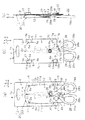
図1(a)に示す第一シートとしての台シート1は、不透明な厚紙により縦方向Z(上下方向)に長い形状に成形され、外周縁部(上縁1aと下縁1bと左縁1cと右縁1d)により囲まれた表面2を有しているとともに、図2(b)に示すようにこの外周縁部により囲まれた裏面3を有している。この台シート1の上半部において、上縁1aよりも若干下方で横方向Y(左右方向)の中央部には吊下孔4が表面2と裏面3との間で貫設されているとともに、この吊下孔4よりも下方の左右両側には左縁1c及び右縁1dよりも若干内側で筋状の切込み5,6が表面2と裏面3との間で貫設されている。この台シート1の下半部において、横方向Yの中央部には円形状の止め孔7が表面2と裏面3との間で貫設されているとともに、この止め孔7よりも若干下方の左右両側には左縁1c及び右縁1dよりも若干内側で筋状の切込み8,9が表面2と裏面3との間で貫設されている。さらに、この止め孔7よりも下方でこの左右両切込み8,9間には一対の索穴10が表面2と裏面3との間で貫設されている。
First, the blade display support member according to the first embodiment of the present invention will be described with reference to FIGS.
A
図1(b)に示す第二シートとしてのカバーシート11は、透明なプラスチック板により縦方向Zに長い形状に成形され、外周縁部(上縁11aと下縁11bと左縁11cと右縁11d)により囲まれた表面12を有しているとともに、図2(c)に示すようにこの外周縁部により囲まれた裏面13を有している。このカバーシート11の上半部において、上縁11aよりも若干下方で左縁11cと右縁11dとには舌片14,15が形成されている。このカバーシート11の下半部において、横方向Yの中央部(上記外周縁部の内側)には開口16が表面12と裏面13との間で貫設されているとともに、この開口16よりも若干下方で左縁11cと右縁11dとには舌片17,18が形成されている。さらに、この開口16よりも下方でこの左右両舌片17,18間には一対の索穴19が表面12と裏面13との間で貫設されている。
A
このように互いに分離されて成形された台シート1とカバーシート11とは、図2(a)(b)(c)に示すように、台シート1の表面2とカバーシート11の裏面13とを相対向させた状態で支持体20として互いに重ねられる。その際、台シート1の上半部の左右両切込み5,6にカバーシート11の上半部の左右両舌片14,15を挿入して結合手段としての第一連結部21にするとともに、台シート1の下半部の左右両切込み8,9にカバーシート11の下半部の左右両舌片17,18を挿入して結合手段としての第二連結部22にしている。この第二連結部22では、左右両切込み8,9の上下両端部に係止部8a,9a,8b,9bが形成されているとともに、左右両舌片17,18の上下両段差部に係止部17a,18a,17b,18bが形成され、この係止部8a,9a,8b,9bと係止部17a,18a,17b,18bとが互いに係止されて、台シート1に対しカバーシート11が縦方向Zへ移動するのを規制して位置決めされている。
As shown in FIGS. 2A, 2B, and 2C, the
前記第一連結部21において、左右両切込み5,6の上下両端部には係止部5a,6a,5b,6bが形成され、L形状をなす左右両舌片14,15は、左縁11c及び右縁11dに沿って上方へ延びる係止腕部14a,15aと、この係止腕部14a,15aと左縁11c及び右縁11dとの間に形成された係止部としての係止溝部14b,15bとを有している。この左右両切込み5,6の係止部5a,6aの間隔Aをこの左右両舌片14,15の係止溝部14b,15bの間隔Bよりも小さくしている。前記第二連結部22において台シート1とカバーシート11とが互いに位置決めされた状態で、台シート1に対しカバーシート11を横方向Y及び縦方向Zへ撓ませてカバーシート11の左右両係止腕部14a,15aを台シート1の左右両切込み5,6に挿入すると、その左右両係止腕部14a,15aを左右両切込み5,6に対し挿脱し得る挿脱可能状態となる。その挿脱可能状態でカバーシート11を離してその撓みをなくすと、カバーシート11の左右両係止溝部14b,15bに左右両切込み5,6の係止部5a,6aが係入されて、左右両舌片14,15が左右両切込み5,6から離脱するのを阻止する係止状態となる。この係止状態ではカバーシート11に膨らみが生じて台シート1とカバーシート11との間に収容室23が形成される。
In the first connecting
図1(c)に示す刃物としての西洋鋏24においては、両鋏片25が開閉中心軸部26で回動可能に支持されて、この開閉中心軸部26よりも先端側に両刃部27が設けられているとともに、この開閉中心軸部26よりも基端側に両柄部28が設けられている。この両柄部28においては、両刃部27から延設された部分に把持環28aが取着され、この把持環28aの内側に接触部としての内周縁部28bが形成されている。この開閉中心軸部26は図2(c)に示すようにボルト26aとナット26bとを有し、このボルト26aとナット26bとが段差状をなすように突出している。
In the
図2(a)(b)(c)に示すように支持体20のカバーシート11においてその表面12側から開口16に鋏24の両刃部27を挿入すると、図3(a)(b)(c)に示すように、その両刃部27が台シート1とカバーシート11との間の収容室23に収容されて覆われ、鋏24の開閉中心軸部26のナット26bが台シート1の止め孔7に係止されるとともに、鋏24の開閉中心軸部26のボルト26aが開口16の内縁部16aに係止される。鋏24の両柄部28の上半部はカバーシート11の表面12側に重ねられ、その両柄部28の下半部で把持環28aの一部が台シート1の下縁1bから下方へ突出する。その後、台シート1の各索穴10とカバーシート11の各索穴19に止め索29を通して鋏24の柄部28に結んで鋏24を支持体20に保持する。この第二連結部22は、開口16の内縁部16aを通る平面(縦方向Zに対し直交する横方向Yの平面)と、閉動状態にある鋏24の両柄部28において把持環28aの内周縁部28bを通る平面(縦方向Zに対し直交する横方向Yの平面)との間の範囲に設けられている。さらに、この第二連結部22は、その範囲内において、縦方向Z(挿入方向)で把持環28aの内周縁部28bよりも開口16の内縁部16aに近い側に配置され、把持環28aの内周縁部28bと開口16の内縁部16aとの間の中央部よりも挿入向きZU側に寄っている。
As shown in FIGS. 2A, 2B and 2C, when the double-edged
このように鋏24を保管した支持体20は吊下孔4により吊り下げられて陳列される。その陳列時に、鋏24の両刃部27を透明なカバーシート11を通して視認することができるとともに、鋏24の両柄部28に直接触れて両柄部28を開閉させることもできる。
Thus, the
図4〜5に示す第2実施形態の刃物陳列用支持部材においては、図4(a)(b)(c)及び図5(a)(b)(c)がそれぞれ第1実施形態の図1(a)(b)(c)及び図3(a)(b)(c)に対応し、下記の点で第1実施形態と主に異なる。 In the blade display support member of the second embodiment shown in FIGS. 4 to 5, FIGS. 4 (a), (b), (c) and FIGS. 5 (a), (b), (c) are diagrams of the first embodiment. It corresponds to 1 (a) (b) (c) and FIGS. 3 (a) (b) (c) and is mainly different from the first embodiment in the following points.
* 第1実施形態の台シート1に形成された止め孔7が省略されている。
* 鋏24の開閉中心軸部26が段差状に突出せず略平坦な形状になっている。
* カバーシート11に形成された逆U状の切込み30aにより開口16に舌片30bが形成されている。
* The
* The opening / closing
* A
* 第二連結部22において、カバーシート11の左右両舌片17,18のうち右側の舌片18で上下両係止溝部18a,18bが形成され、台シート1の左右両切込み8,9のうち右側の切込み9で形成された上下両係止部9a,9bに対しこの上下両係止溝部18a,18bが係止されて不用意に抜け落ちないように引き掛けられる。
* In the second connecting
図示しないが、前記実施形態以外にも下記のように構成してもよい。
* 刃物としては、西洋鋏や握り鋏などの鋏以外に、包丁やナイフや医療用メスや剃刀や爪切りや皮むきなどを採用する。
Although not shown, the following configuration may be adopted in addition to the above embodiment.
* As knives, knifes, knives, scalpels, razors, nail clippers, and peelers will be used in addition to scissors such as western and hand grips.
* カバーシートばかりではなく台シートも透明なプラスチックにより成形する。
* 第二連結部については、互いに分離して設けた台シートの下縁とカバーシートの下縁とを接着したり、台シートの下縁とカバーシートの下縁とを互いに折曲可能に一体成形する。また、台シートの左縁とカバーシートの左縁とを互いに折曲可能に一体成形したり、台シートの右縁とカバーシートの右縁とを互いに折曲可能に一体成形する。
* Not only the cover sheet but also the base sheet is molded from transparent plastic.
* For the second connecting part, the lower edge of the base sheet and the lower edge of the cover sheet that are provided separately from each other can be bonded, or the lower edge of the base sheet and the lower edge of the cover sheet can be folded together Mold. Further, the left edge of the base sheet and the left edge of the cover sheet are integrally formed so as to be bendable, or the right edge of the base sheet and the right edge of the cover sheet are integrally formed so as to be bendable.
* 鋏の両刃部の全体をカバーシートにより覆う必要はないが、少なくとも両刃部の先端部を覆うことが好ましい。
* 両側の第一連結部のうち、一方の第一連結部の切込みの係止部と他方の第一連結部の切込みの係止部との間の間隔を、一方の第一連結部の舌片の係止部と他方の第一連結部の舌片の係止部との間の間隔よりも大きくすることにより、係止状態で両側の第一連結部間の台シートに膨らみを持たせて収容室を形成することができる。
* Although it is not necessary to cover the whole blade part of the scissors with the cover sheet, it is preferable to cover at least the tip part of the blade part.
* Of the first connecting portions on both sides, the distance between the notched locking portion of one first connecting portion and the notched locking portion of the other first connecting portion is set to the tongue of one first connecting portion. By making it larger than the distance between the locking portion of one piece and the locking portion of the tongue piece of the other first connecting portion, the base sheet between the first connecting portions on both sides is made to bulge in the locked state. A storage chamber can be formed.
* 鋏の収容状態で両柄部の全体をカバーシートの外側に重ねる。
* 台シート及びカバーシートの材質や形態や寸法を適宜変更する。また、鋏の形態や大きさに応じて台シート及びカバーシートを選択する。さらに、台シート及びカバーシートに印刷や商品説明を付す。
* Overlay the entire handle on the outside of the cover sheet in the stowed state.
* Change the material, form and dimensions of the base sheet and cover sheet as appropriate. Further, the base sheet and the cover sheet are selected according to the shape and size of the ridge. In addition, printing and product descriptions are attached to the base sheet and the cover sheet.
1…第一シートとしての台シート、5,6,8,9…切込み、5a,6a…切込みの係止部、7…止め手段としての止め孔、11…第二シートとしてのカバーシート、14,15,17,18…舌片、14b,15b…係止部としての舌片の係止溝部、16…開口、16a…止め手段としての開口の内周縁、20…支持体、21…結合手段としての第一連結部、22…結合手段としての第二連結部、23…収容室、24…刃物としての鋏、27…刃部、28…柄部、29…止め手段としての止め索、A,B…間隔。
DESCRIPTION OF
Claims (5)
この第二シートにはその外周縁部の内側に開口を設け、その開口からこの第一シートと第二シートとの間の収容室に刃物の刃部を挿入して第一シート及び第二シートにより覆うとともに、この収容室の開口から露出する刃物の柄部を第二シートの外側に重ね、この刃物を支持体に保持する止め手段を設け、
前記結合手段は、開口に対し刃部を挿入する方向の両側のうち、その刃部の挿入向き側でその挿入方向に対し直交する方向の両側にそれぞれ設けられた第一連結部と、その挿入向きに対する反対側で設けられた第二連結部とを備え、
前記両側の第一連結部は、第一シートと第二シートとのうち、一方のシートに設けた切込みと、他方のシートに設けた舌片とを有し、この切込みにこの舌片を挿入したものであって、
前記両側の第一連結部では、前記第二連結部により第一シートと第二シートとを互いに位置決めした状態で、第一シートと第二シートとを相対動させて切込みに対し舌片を挿脱し得る挿脱可能状態と、舌片が切込みに挿入された挿脱可能状態で第一シートと第二シートとの相対動により舌片に設けた係止部が切込みの係止部に係止されて舌片が切込みから離脱するのを阻止する係止状態とを取る
ことを特徴とする刃物陳列用支持部材。 Holding the support body in which the first sheet and the second sheet provided separately from each other are held together by the coupling means,
The second sheet is provided with an opening inside the outer peripheral edge portion, and the blade portion of the blade is inserted into the storage chamber between the first sheet and the second sheet from the opening, and the first sheet and the second sheet covering the overlaid the handle portion of the tool exposed from the opening of the accommodation chamber to the outside of the second sheet, set the stop means for holding the blade to the support,
The coupling means includes a first connecting portion provided on both sides in a direction perpendicular to the insertion direction on the insertion direction side of the blade portion, on both sides in a direction in which the blade portion is inserted into the opening, and the insertion thereof. A second connecting portion provided on the opposite side to the orientation,
The first connecting portions on both sides have a notch provided in one of the first sheet and the second sheet and a tongue provided in the other sheet, and the tongue is inserted into this notch. Which
In the first connecting parts on both sides, the first sheet and the second sheet are positioned relative to each other by the second connecting part, and the first sheet and the second sheet are moved relative to each other to insert the tongue pieces into the cuts. The locking part provided on the tongue piece is locked to the locking part of the notch by the relative movement of the first sheet and the second sheet in the insertable / detachable state where the tongue piece is inserted and the tongue piece is inserted into the notch. And a locking state for preventing the tongue piece from being detached from the notch .
Priority Applications (4)
| Application Number | Priority Date | Filing Date | Title |
|---|---|---|---|
| JP2006053244A JP4837397B2 (en) | 2006-02-28 | 2006-02-28 | Support member for blade display |
| PCT/JP2007/053562 WO2007099923A1 (en) | 2006-02-28 | 2007-02-27 | Support member for edged tool |
| EP07714955A EP1990292B1 (en) | 2006-02-28 | 2007-02-27 | Support member for edged tool |
| US12/224,493 US20090065386A1 (en) | 2006-02-28 | 2007-02-27 | Support Member for Edged Tool |
Applications Claiming Priority (1)
| Application Number | Priority Date | Filing Date | Title |
|---|---|---|---|
| JP2006053244A JP4837397B2 (en) | 2006-02-28 | 2006-02-28 | Support member for blade display |
Publications (2)
| Publication Number | Publication Date |
|---|---|
| JP2007230594A JP2007230594A (en) | 2007-09-13 |
| JP4837397B2 true JP4837397B2 (en) | 2011-12-14 |
Family
ID=38459029
Family Applications (1)
| Application Number | Title | Priority Date | Filing Date |
|---|---|---|---|
| JP2006053244A Expired - Fee Related JP4837397B2 (en) | 2006-02-28 | 2006-02-28 | Support member for blade display |
Country Status (4)
| Country | Link |
|---|---|
| US (1) | US20090065386A1 (en) |
| EP (1) | EP1990292B1 (en) |
| JP (1) | JP4837397B2 (en) |
| WO (1) | WO2007099923A1 (en) |
Families Citing this family (14)
| Publication number | Priority date | Publication date | Assignee | Title |
|---|---|---|---|---|
| US7789234B2 (en) * | 2007-02-08 | 2010-09-07 | Wayne Clark | Display package for scissors |
| US10160126B2 (en) * | 2009-12-16 | 2018-12-25 | Laura Ranieri | Protective sheath for securing a blade of a cutlery implement |
| US8322531B2 (en) | 2010-05-05 | 2012-12-04 | Stanley Black & Decker, Inc. | Twin blade knife package |
| KR101487280B1 (en) * | 2013-12-07 | 2015-01-28 | 박수형 | Hand driving tool exposure packaging case |
| KR101478481B1 (en) * | 2014-01-20 | 2014-12-31 | 이랄라 | packaging case for waterproof pack |
| US9480347B2 (en) * | 2014-08-28 | 2016-11-01 | B&G Plastics, Inc. | Jewelry display hanger with cable tie |
| US10220995B2 (en) * | 2015-01-07 | 2019-03-05 | Westrock Mwv, Llc | Blister card with flange strap |
| US20160303731A1 (en) * | 2015-04-14 | 2016-10-20 | James Edwin Barlow | Hand Tool and Retainer |
| CN107635882B (en) * | 2015-04-30 | 2018-09-25 | 胡斯华纳有限公司 | Packaging for cutting equipment and the cutting equipment packed |
| US11203476B2 (en) * | 2018-11-02 | 2021-12-21 | Westrock Mwv, Llc | Product package, display card, clip and blank therefor |
| GB2583554A (en) * | 2019-04-30 | 2020-11-04 | Monument Tools Ltd | Pipe cutter |
| US11717371B2 (en) * | 2020-02-03 | 2023-08-08 | SterileBits, Inc. | Instrument protector backer card |
| EP3981705A1 (en) * | 2020-10-06 | 2022-04-13 | Husqvarna Ab | Package for cutting tool |
| US20230211942A1 (en) * | 2021-12-30 | 2023-07-06 | RMX Industries | Weather resistant plastic packaging |
Family Cites Families (16)
| Publication number | Priority date | Publication date | Assignee | Title |
|---|---|---|---|---|
| JPS5119276Y2 (en) * | 1972-10-11 | 1976-05-20 | ||
| JPS4988363A (en) * | 1972-12-28 | 1974-08-23 | ||
| JPS52114984U (en) * | 1976-02-26 | 1977-08-31 | ||
| US4179029A (en) * | 1978-06-01 | 1979-12-18 | Fiskars Manufacturing Corporation | Functional blister package for snipper-type scissors |
| US4165805A (en) * | 1978-06-01 | 1979-08-28 | Fiskars Manufacturing Corporation | Blister packages for scissors, pliers and other hand tools |
| FI72480C (en) * | 1985-08-29 | 1987-06-08 | Fiskars Ab Oy | FOERPACKNING FOER SAXAR. |
| US5279417A (en) * | 1992-07-14 | 1994-01-18 | Fiskars Oy Ab | Package for hand tools |
| US5291996A (en) * | 1993-01-15 | 1994-03-08 | Fiskars Oy Ab | Reusable display sheath with frangible latch means |
| JPH0685269U (en) * | 1993-05-19 | 1994-12-06 | 協永産業株式会社 | Product packaging |
| US5435447A (en) * | 1994-02-22 | 1995-07-25 | Acme United Corporation | Product holding and displaying member |
| US5477964A (en) * | 1994-12-27 | 1995-12-26 | The Stanley Works | Package for an elongated tool |
| US20020100704A1 (en) * | 2001-01-26 | 2002-08-01 | Hp Intellectual Corp. | Mounting and display card for hand operated tool |
| US6854184B2 (en) * | 2002-02-26 | 2005-02-15 | Ek Success, Ltd. | Blade cover for cutting device |
| JP4399247B2 (en) * | 2003-12-25 | 2010-01-13 | 株式会社貝印刃物開発センター | Support member for display |
| US20060113205A1 (en) * | 2004-12-01 | 2006-06-01 | Cheng-Chih Liu | Display package |
| US7789234B2 (en) * | 2007-02-08 | 2010-09-07 | Wayne Clark | Display package for scissors |
-
2006
- 2006-02-28 JP JP2006053244A patent/JP4837397B2/en not_active Expired - Fee Related
-
2007
- 2007-02-27 EP EP07714955A patent/EP1990292B1/en not_active Expired - Fee Related
- 2007-02-27 WO PCT/JP2007/053562 patent/WO2007099923A1/en active Application Filing
- 2007-02-27 US US12/224,493 patent/US20090065386A1/en not_active Abandoned
Also Published As
| Publication number | Publication date |
|---|---|
| EP1990292A4 (en) | 2009-12-23 |
| WO2007099923A1 (en) | 2007-09-07 |
| EP1990292B1 (en) | 2012-07-18 |
| JP2007230594A (en) | 2007-09-13 |
| US20090065386A1 (en) | 2009-03-12 |
| EP1990292A1 (en) | 2008-11-12 |
Similar Documents
| Publication | Publication Date | Title |
|---|---|---|
| JP4837397B2 (en) | Support member for blade display | |
| JP5125189B2 (en) | Packaging container | |
| JP2009143597A (en) | Lid for container | |
| KR101739773B1 (en) | Connection member | |
| JP4399247B2 (en) | Support member for display | |
| JP6407572B2 (en) | Compact case and protective sheet for makeup | |
| JP6975670B2 (en) | Household tissue paper storage container | |
| JP4883971B2 (en) | scissors | |
| USD565345S1 (en) | Handle portion for a utensil | |
| CN213229325U (en) | Express delivery unsealing device | |
| JP2008125546A (en) | Buckle for back pack band | |
| TWI276520B (en) | A stackable barber scissors | |
| JP4574190B2 (en) | Nail clippers | |
| JP2009184706A (en) | Product | |
| JP3039742U (en) | Packaging case | |
| JP3221303U (en) | Packaging board | |
| USD578367S1 (en) | Utility knife handle | |
| JP4897765B2 (en) | String storage case with cutter | |
| JP6994298B2 (en) | Nail cutting | |
| JP2005035657A (en) | Bag opening cutter | |
| JP3048185U (en) | Safety razor display packaging bag | |
| JP5714866B2 (en) | scissors | |
| TWM379499U (en) | Scissor-type Tool | |
| JP6083912B2 (en) | clear file | |
| JP2012229050A (en) | Packaging box with handle |
Legal Events
| Date | Code | Title | Description |
|---|---|---|---|
| A621 | Written request for application examination |
Free format text: JAPANESE INTERMEDIATE CODE: A621 Effective date: 20090220 |
|
| A131 | Notification of reasons for refusal |
Free format text: JAPANESE INTERMEDIATE CODE: A131 Effective date: 20110719 |
|
| A521 | Written amendment |
Free format text: JAPANESE INTERMEDIATE CODE: A523 Effective date: 20110826 |
|
| TRDD | Decision of grant or rejection written | ||
| A01 | Written decision to grant a patent or to grant a registration (utility model) |
Free format text: JAPANESE INTERMEDIATE CODE: A01 Effective date: 20110920 |
|
| A01 | Written decision to grant a patent or to grant a registration (utility model) |
Free format text: JAPANESE INTERMEDIATE CODE: A01 |
|
| A61 | First payment of annual fees (during grant procedure) |
Free format text: JAPANESE INTERMEDIATE CODE: A61 Effective date: 20110928 |
|
| FPAY | Renewal fee payment (event date is renewal date of database) |
Free format text: PAYMENT UNTIL: 20141007 Year of fee payment: 3 |
|
| R150 | Certificate of patent or registration of utility model |
Free format text: JAPANESE INTERMEDIATE CODE: R150 Ref document number: 4837397 Country of ref document: JP Free format text: JAPANESE INTERMEDIATE CODE: R150 |
|
| R250 | Receipt of annual fees |
Free format text: JAPANESE INTERMEDIATE CODE: R250 |
|
| R250 | Receipt of annual fees |
Free format text: JAPANESE INTERMEDIATE CODE: R250 |
|
| LAPS | Cancellation because of no payment of annual fees |