JP4837231B2 - Rapid densification of porous material (preform) using resin transfer molding process with high viscosity resin or pitch - Google Patents
Rapid densification of porous material (preform) using resin transfer molding process with high viscosity resin or pitch Download PDFInfo
- Publication number
- JP4837231B2 JP4837231B2 JP2002523071A JP2002523071A JP4837231B2 JP 4837231 B2 JP4837231 B2 JP 4837231B2 JP 2002523071 A JP2002523071 A JP 2002523071A JP 2002523071 A JP2002523071 A JP 2002523071A JP 4837231 B2 JP4837231 B2 JP 4837231B2
- Authority
- JP
- Japan
- Prior art keywords
- mold
- resin
- pitch
- preform
- rapid
- Prior art date
- Legal status (The legal status is an assumption and is not a legal conclusion. Google has not performed a legal analysis and makes no representation as to the accuracy of the status listed.)
- Expired - Fee Related
Links
- 229920005989 resin Polymers 0.000 title claims abstract description 201
- 239000011347 resin Substances 0.000 title claims abstract description 201
- 238000000034 method Methods 0.000 title claims abstract description 75
- 230000008569 process Effects 0.000 title claims abstract description 53
- 238000001721 transfer moulding Methods 0.000 title claims abstract 5
- 238000000280 densification Methods 0.000 title description 22
- 239000011148 porous material Substances 0.000 title description 5
- 238000013022 venting Methods 0.000 claims abstract description 9
- 238000001816 cooling Methods 0.000 claims abstract description 3
- 238000000465 moulding Methods 0.000 claims description 24
- 238000002844 melting Methods 0.000 claims description 15
- 230000008018 melting Effects 0.000 claims description 15
- 229910052760 oxygen Inorganic materials 0.000 claims description 15
- 239000001301 oxygen Substances 0.000 claims description 15
- QVGXLLKOCUKJST-UHFFFAOYSA-N atomic oxygen Chemical compound [O] QVGXLLKOCUKJST-UHFFFAOYSA-N 0.000 claims description 14
- 238000010438 heat treatment Methods 0.000 claims description 12
- 239000002131 composite material Substances 0.000 claims description 11
- 239000000463 material Substances 0.000 claims description 11
- 239000007789 gas Substances 0.000 claims description 6
- 230000003647 oxidation Effects 0.000 claims description 5
- 238000007254 oxidation reaction Methods 0.000 claims description 5
- 238000013459 approach Methods 0.000 claims description 3
- CREMABGTGYGIQB-UHFFFAOYSA-N carbon carbon Chemical compound C.C CREMABGTGYGIQB-UHFFFAOYSA-N 0.000 claims description 3
- 239000011203 carbon fibre reinforced carbon Substances 0.000 claims description 3
- 238000012546 transfer Methods 0.000 claims description 3
- 230000001590 oxidative effect Effects 0.000 claims description 2
- 230000000087 stabilizing effect Effects 0.000 claims description 2
- 230000000452 restraining effect Effects 0.000 claims 2
- 238000011049 filling Methods 0.000 abstract description 3
- 239000011295 pitch Substances 0.000 description 64
- 238000001764 infiltration Methods 0.000 description 30
- 230000008595 infiltration Effects 0.000 description 30
- OKTJSMMVPCPJKN-UHFFFAOYSA-N Carbon Chemical compound [C] OKTJSMMVPCPJKN-UHFFFAOYSA-N 0.000 description 29
- 229910052799 carbon Inorganic materials 0.000 description 26
- 239000000835 fiber Substances 0.000 description 21
- 239000011302 mesophase pitch Substances 0.000 description 20
- 238000005470 impregnation Methods 0.000 description 18
- 238000002347 injection Methods 0.000 description 17
- 239000007924 injection Substances 0.000 description 17
- 230000035515 penetration Effects 0.000 description 15
- 238000003763 carbonization Methods 0.000 description 13
- 230000006641 stabilisation Effects 0.000 description 10
- 238000011105 stabilization Methods 0.000 description 10
- 239000000155 melt Substances 0.000 description 9
- 238000001125 extrusion Methods 0.000 description 8
- 238000009745 resin transfer moulding Methods 0.000 description 8
- 239000003039 volatile agent Substances 0.000 description 8
- 239000006260 foam Substances 0.000 description 7
- 239000011159 matrix material Substances 0.000 description 7
- 238000012545 processing Methods 0.000 description 7
- 229920001187 thermosetting polymer Polymers 0.000 description 7
- 230000008901 benefit Effects 0.000 description 6
- 239000000919 ceramic Substances 0.000 description 6
- 238000004519 manufacturing process Methods 0.000 description 6
- VNWKTOKETHGBQD-UHFFFAOYSA-N methane Chemical compound C VNWKTOKETHGBQD-UHFFFAOYSA-N 0.000 description 6
- 238000002156 mixing Methods 0.000 description 6
- 229920000049 Carbon (fiber) Polymers 0.000 description 5
- 239000004917 carbon fiber Substances 0.000 description 5
- 238000013461 design Methods 0.000 description 5
- 125000006850 spacer group Chemical group 0.000 description 5
- XAGFODPZIPBFFR-UHFFFAOYSA-N aluminium Chemical compound [Al] XAGFODPZIPBFFR-UHFFFAOYSA-N 0.000 description 4
- 229910052782 aluminium Inorganic materials 0.000 description 4
- 239000012298 atmosphere Substances 0.000 description 4
- 238000005516 engineering process Methods 0.000 description 4
- 239000004744 fabric Substances 0.000 description 4
- 239000011301 petroleum pitch Substances 0.000 description 4
- 239000004604 Blowing Agent Substances 0.000 description 3
- 239000011280 coal tar Substances 0.000 description 3
- 230000007423 decrease Effects 0.000 description 3
- 238000001746 injection moulding Methods 0.000 description 3
- 239000007788 liquid Substances 0.000 description 3
- 239000004745 nonwoven fabric Substances 0.000 description 3
- 239000003921 oil Substances 0.000 description 3
- 229920000642 polymer Polymers 0.000 description 3
- 239000002243 precursor Substances 0.000 description 3
- 238000000197 pyrolysis Methods 0.000 description 3
- 230000003068 static effect Effects 0.000 description 3
- 229920001169 thermoplastic Polymers 0.000 description 3
- 229920005992 thermoplastic resin Polymers 0.000 description 3
- 239000004416 thermosoftening plastic Substances 0.000 description 3
- UFWIBTONFRDIAS-UHFFFAOYSA-N Naphthalene Chemical compound C1=CC=CC2=CC=CC=C21 UFWIBTONFRDIAS-UHFFFAOYSA-N 0.000 description 2
- 239000000654 additive Substances 0.000 description 2
- 239000011336 carbonized pitch Substances 0.000 description 2
- 239000011294 coal tar pitch Substances 0.000 description 2
- 239000000571 coke Substances 0.000 description 2
- 238000007872 degassing Methods 0.000 description 2
- 230000032798 delamination Effects 0.000 description 2
- 229910002804 graphite Inorganic materials 0.000 description 2
- 239000010439 graphite Substances 0.000 description 2
- 238000005087 graphitization Methods 0.000 description 2
- 239000006082 mold release agent Substances 0.000 description 2
- 239000008188 pellet Substances 0.000 description 2
- 239000000843 powder Substances 0.000 description 2
- 239000002296 pyrolytic carbon Substances 0.000 description 2
- 239000000126 substance Substances 0.000 description 2
- 239000011318 synthetic pitch Substances 0.000 description 2
- 239000002699 waste material Substances 0.000 description 2
- 230000004580 weight loss Effects 0.000 description 2
- IJGRMHOSHXDMSA-UHFFFAOYSA-N Atomic nitrogen Chemical compound N#N IJGRMHOSHXDMSA-UHFFFAOYSA-N 0.000 description 1
- 241001470502 Auzakia danava Species 0.000 description 1
- ZOXJGFHDIHLPTG-UHFFFAOYSA-N Boron Chemical compound [B] ZOXJGFHDIHLPTG-UHFFFAOYSA-N 0.000 description 1
- 239000004971 Cross linker Substances 0.000 description 1
- ISWSIDIOOBJBQZ-UHFFFAOYSA-N Phenol Chemical compound OC1=CC=CC=C1 ISWSIDIOOBJBQZ-UHFFFAOYSA-N 0.000 description 1
- OAICVXFJPJFONN-UHFFFAOYSA-N Phosphorus Chemical compound [P] OAICVXFJPJFONN-UHFFFAOYSA-N 0.000 description 1
- 238000007792 addition Methods 0.000 description 1
- 239000003963 antioxidant agent Substances 0.000 description 1
- 239000011324 bead Substances 0.000 description 1
- 230000015572 biosynthetic process Effects 0.000 description 1
- 229910052796 boron Inorganic materials 0.000 description 1
- 150000001721 carbon Chemical class 0.000 description 1
- 239000007833 carbon precursor Substances 0.000 description 1
- 238000010000 carbonizing Methods 0.000 description 1
- 230000003197 catalytic effect Effects 0.000 description 1
- 238000006243 chemical reaction Methods 0.000 description 1
- 239000003795 chemical substances by application Substances 0.000 description 1
- 239000011248 coating agent Substances 0.000 description 1
- 238000000576 coating method Methods 0.000 description 1
- 150000001875 compounds Chemical class 0.000 description 1
- 238000005520 cutting process Methods 0.000 description 1
- 230000008021 deposition Effects 0.000 description 1
- 238000010586 diagram Methods 0.000 description 1
- 229910001873 dinitrogen Inorganic materials 0.000 description 1
- 238000005553 drilling Methods 0.000 description 1
- 238000001035 drying Methods 0.000 description 1
- 238000011156 evaluation Methods 0.000 description 1
- 238000002474 experimental method Methods 0.000 description 1
- 238000004880 explosion Methods 0.000 description 1
- 238000000605 extraction Methods 0.000 description 1
- 239000003337 fertilizer Substances 0.000 description 1
- 239000003733 fiber-reinforced composite Substances 0.000 description 1
- 239000012467 final product Substances 0.000 description 1
- 238000005187 foaming Methods 0.000 description 1
- 238000001513 hot isostatic pressing Methods 0.000 description 1
- 239000004973 liquid crystal related substance Substances 0.000 description 1
- 239000012705 liquid precursor Substances 0.000 description 1
- 238000003754 machining Methods 0.000 description 1
- 239000000203 mixture Substances 0.000 description 1
- 238000012986 modification Methods 0.000 description 1
- 230000004048 modification Effects 0.000 description 1
- 239000012299 nitrogen atmosphere Substances 0.000 description 1
- 230000003204 osmotic effect Effects 0.000 description 1
- 150000002926 oxygen Chemical class 0.000 description 1
- 239000002245 particle Substances 0.000 description 1
- 239000003208 petroleum Substances 0.000 description 1
- 229910052698 phosphorus Inorganic materials 0.000 description 1
- 239000011574 phosphorus Substances 0.000 description 1
- 239000004033 plastic Substances 0.000 description 1
- 229920003023 plastic Polymers 0.000 description 1
- 238000002203 pretreatment Methods 0.000 description 1
- 238000011112 process operation Methods 0.000 description 1
- 239000000047 product Substances 0.000 description 1
- 238000004080 punching Methods 0.000 description 1
- 239000002994 raw material Substances 0.000 description 1
- 230000009467 reduction Effects 0.000 description 1
- 230000004044 response Effects 0.000 description 1
- 150000004760 silicates Chemical class 0.000 description 1
- 239000002210 silicon-based material Substances 0.000 description 1
- 238000004088 simulation Methods 0.000 description 1
- 239000007787 solid Substances 0.000 description 1
- 239000011343 solid material Substances 0.000 description 1
- 239000000243 solution Substances 0.000 description 1
- 229910001220 stainless steel Inorganic materials 0.000 description 1
- 239000010935 stainless steel Substances 0.000 description 1
- 238000012360 testing method Methods 0.000 description 1
- 239000004753 textile Substances 0.000 description 1
- 238000007514 turning Methods 0.000 description 1
- 238000005303 weighing Methods 0.000 description 1
Images


Classifications
-
- B—PERFORMING OPERATIONS; TRANSPORTING
- B29—WORKING OF PLASTICS; WORKING OF SUBSTANCES IN A PLASTIC STATE IN GENERAL
- B29C—SHAPING OR JOINING OF PLASTICS; SHAPING OF MATERIAL IN A PLASTIC STATE, NOT OTHERWISE PROVIDED FOR; AFTER-TREATMENT OF THE SHAPED PRODUCTS, e.g. REPAIRING
- B29C45/00—Injection moulding, i.e. forcing the required volume of moulding material through a nozzle into a closed mould; Apparatus therefor
- B29C45/14—Injection moulding, i.e. forcing the required volume of moulding material through a nozzle into a closed mould; Apparatus therefor incorporating preformed parts or layers, e.g. injection moulding around inserts or for coating articles
-
- C—CHEMISTRY; METALLURGY
- C04—CEMENTS; CONCRETE; ARTIFICIAL STONE; CERAMICS; REFRACTORIES
- C04B—LIME, MAGNESIA; SLAG; CEMENTS; COMPOSITIONS THEREOF, e.g. MORTARS, CONCRETE OR LIKE BUILDING MATERIALS; ARTIFICIAL STONE; CERAMICS; REFRACTORIES; TREATMENT OF NATURAL STONE
- C04B35/00—Shaped ceramic products characterised by their composition; Ceramics compositions; Processing powders of inorganic compounds preparatory to the manufacturing of ceramic products
- C04B35/71—Ceramic products containing macroscopic reinforcing agents
- C04B35/78—Ceramic products containing macroscopic reinforcing agents containing non-metallic materials
- C04B35/80—Fibres, filaments, whiskers, platelets, or the like
- C04B35/83—Carbon fibres in a carbon matrix
-
- B—PERFORMING OPERATIONS; TRANSPORTING
- B29—WORKING OF PLASTICS; WORKING OF SUBSTANCES IN A PLASTIC STATE IN GENERAL
- B29C—SHAPING OR JOINING OF PLASTICS; SHAPING OF MATERIAL IN A PLASTIC STATE, NOT OTHERWISE PROVIDED FOR; AFTER-TREATMENT OF THE SHAPED PRODUCTS, e.g. REPAIRING
- B29C70/00—Shaping composites, i.e. plastics material comprising reinforcements, fillers or preformed parts, e.g. inserts
- B29C70/04—Shaping composites, i.e. plastics material comprising reinforcements, fillers or preformed parts, e.g. inserts comprising reinforcements only, e.g. self-reinforcing plastics
- B29C70/28—Shaping operations therefor
- B29C70/40—Shaping or impregnating by compression not applied
- B29C70/42—Shaping or impregnating by compression not applied for producing articles of definite length, i.e. discrete articles
- B29C70/46—Shaping or impregnating by compression not applied for producing articles of definite length, i.e. discrete articles using matched moulds, e.g. for deforming sheet moulding compounds [SMC] or prepregs
- B29C70/48—Shaping or impregnating by compression not applied for producing articles of definite length, i.e. discrete articles using matched moulds, e.g. for deforming sheet moulding compounds [SMC] or prepregs and impregnating the reinforcements in the closed mould, e.g. resin transfer moulding [RTM], e.g. by vacuum
-
- C—CHEMISTRY; METALLURGY
- C04—CEMENTS; CONCRETE; ARTIFICIAL STONE; CERAMICS; REFRACTORIES
- C04B—LIME, MAGNESIA; SLAG; CEMENTS; COMPOSITIONS THEREOF, e.g. MORTARS, CONCRETE OR LIKE BUILDING MATERIALS; ARTIFICIAL STONE; CERAMICS; REFRACTORIES; TREATMENT OF NATURAL STONE
- C04B35/00—Shaped ceramic products characterised by their composition; Ceramics compositions; Processing powders of inorganic compounds preparatory to the manufacturing of ceramic products
- C04B35/515—Shaped ceramic products characterised by their composition; Ceramics compositions; Processing powders of inorganic compounds preparatory to the manufacturing of ceramic products based on non-oxide ceramics
- C04B35/52—Shaped ceramic products characterised by their composition; Ceramics compositions; Processing powders of inorganic compounds preparatory to the manufacturing of ceramic products based on non-oxide ceramics based on carbon, e.g. graphite
- C04B35/521—Shaped ceramic products characterised by their composition; Ceramics compositions; Processing powders of inorganic compounds preparatory to the manufacturing of ceramic products based on non-oxide ceramics based on carbon, e.g. graphite obtained by impregnation of carbon products with a carbonisable material
-
- C—CHEMISTRY; METALLURGY
- C04—CEMENTS; CONCRETE; ARTIFICIAL STONE; CERAMICS; REFRACTORIES
- C04B—LIME, MAGNESIA; SLAG; CEMENTS; COMPOSITIONS THEREOF, e.g. MORTARS, CONCRETE OR LIKE BUILDING MATERIALS; ARTIFICIAL STONE; CERAMICS; REFRACTORIES; TREATMENT OF NATURAL STONE
- C04B35/00—Shaped ceramic products characterised by their composition; Ceramics compositions; Processing powders of inorganic compounds preparatory to the manufacturing of ceramic products
- C04B35/515—Shaped ceramic products characterised by their composition; Ceramics compositions; Processing powders of inorganic compounds preparatory to the manufacturing of ceramic products based on non-oxide ceramics
- C04B35/52—Shaped ceramic products characterised by their composition; Ceramics compositions; Processing powders of inorganic compounds preparatory to the manufacturing of ceramic products based on non-oxide ceramics based on carbon, e.g. graphite
- C04B35/522—Graphite
-
- C—CHEMISTRY; METALLURGY
- C04—CEMENTS; CONCRETE; ARTIFICIAL STONE; CERAMICS; REFRACTORIES
- C04B—LIME, MAGNESIA; SLAG; CEMENTS; COMPOSITIONS THEREOF, e.g. MORTARS, CONCRETE OR LIKE BUILDING MATERIALS; ARTIFICIAL STONE; CERAMICS; REFRACTORIES; TREATMENT OF NATURAL STONE
- C04B35/00—Shaped ceramic products characterised by their composition; Ceramics compositions; Processing powders of inorganic compounds preparatory to the manufacturing of ceramic products
- C04B35/515—Shaped ceramic products characterised by their composition; Ceramics compositions; Processing powders of inorganic compounds preparatory to the manufacturing of ceramic products based on non-oxide ceramics
- C04B35/52—Shaped ceramic products characterised by their composition; Ceramics compositions; Processing powders of inorganic compounds preparatory to the manufacturing of ceramic products based on non-oxide ceramics based on carbon, e.g. graphite
- C04B35/524—Shaped ceramic products characterised by their composition; Ceramics compositions; Processing powders of inorganic compounds preparatory to the manufacturing of ceramic products based on non-oxide ceramics based on carbon, e.g. graphite obtained from polymer precursors, e.g. glass-like carbon material
-
- F—MECHANICAL ENGINEERING; LIGHTING; HEATING; WEAPONS; BLASTING
- F16—ENGINEERING ELEMENTS AND UNITS; GENERAL MEASURES FOR PRODUCING AND MAINTAINING EFFECTIVE FUNCTIONING OF MACHINES OR INSTALLATIONS; THERMAL INSULATION IN GENERAL
- F16D—COUPLINGS FOR TRANSMITTING ROTATION; CLUTCHES; BRAKES
- F16D69/00—Friction linings; Attachment thereof; Selection of coacting friction substances or surfaces
- F16D69/02—Composition of linings ; Methods of manufacturing
- F16D69/023—Composite materials containing carbon and carbon fibres or fibres made of carbonizable material
-
- C—CHEMISTRY; METALLURGY
- C04—CEMENTS; CONCRETE; ARTIFICIAL STONE; CERAMICS; REFRACTORIES
- C04B—LIME, MAGNESIA; SLAG; CEMENTS; COMPOSITIONS THEREOF, e.g. MORTARS, CONCRETE OR LIKE BUILDING MATERIALS; ARTIFICIAL STONE; CERAMICS; REFRACTORIES; TREATMENT OF NATURAL STONE
- C04B2235/00—Aspects relating to ceramic starting mixtures or sintered ceramic products
- C04B2235/60—Aspects relating to the preparation, properties or mechanical treatment of green bodies or pre-forms
- C04B2235/602—Making the green bodies or pre-forms by moulding
- C04B2235/6021—Extrusion moulding
-
- C—CHEMISTRY; METALLURGY
- C04—CEMENTS; CONCRETE; ARTIFICIAL STONE; CERAMICS; REFRACTORIES
- C04B—LIME, MAGNESIA; SLAG; CEMENTS; COMPOSITIONS THEREOF, e.g. MORTARS, CONCRETE OR LIKE BUILDING MATERIALS; ARTIFICIAL STONE; CERAMICS; REFRACTORIES; TREATMENT OF NATURAL STONE
- C04B2235/00—Aspects relating to ceramic starting mixtures or sintered ceramic products
- C04B2235/60—Aspects relating to the preparation, properties or mechanical treatment of green bodies or pre-forms
- C04B2235/602—Making the green bodies or pre-forms by moulding
- C04B2235/6022—Injection moulding
-
- C—CHEMISTRY; METALLURGY
- C04—CEMENTS; CONCRETE; ARTIFICIAL STONE; CERAMICS; REFRACTORIES
- C04B—LIME, MAGNESIA; SLAG; CEMENTS; COMPOSITIONS THEREOF, e.g. MORTARS, CONCRETE OR LIKE BUILDING MATERIALS; ARTIFICIAL STONE; CERAMICS; REFRACTORIES; TREATMENT OF NATURAL STONE
- C04B2235/00—Aspects relating to ceramic starting mixtures or sintered ceramic products
- C04B2235/60—Aspects relating to the preparation, properties or mechanical treatment of green bodies or pre-forms
- C04B2235/614—Gas infiltration of green bodies or pre-forms
-
- C—CHEMISTRY; METALLURGY
- C04—CEMENTS; CONCRETE; ARTIFICIAL STONE; CERAMICS; REFRACTORIES
- C04B—LIME, MAGNESIA; SLAG; CEMENTS; COMPOSITIONS THEREOF, e.g. MORTARS, CONCRETE OR LIKE BUILDING MATERIALS; ARTIFICIAL STONE; CERAMICS; REFRACTORIES; TREATMENT OF NATURAL STONE
- C04B2235/00—Aspects relating to ceramic starting mixtures or sintered ceramic products
- C04B2235/60—Aspects relating to the preparation, properties or mechanical treatment of green bodies or pre-forms
- C04B2235/616—Liquid infiltration of green bodies or pre-forms
-
- C—CHEMISTRY; METALLURGY
- C04—CEMENTS; CONCRETE; ARTIFICIAL STONE; CERAMICS; REFRACTORIES
- C04B—LIME, MAGNESIA; SLAG; CEMENTS; COMPOSITIONS THEREOF, e.g. MORTARS, CONCRETE OR LIKE BUILDING MATERIALS; ARTIFICIAL STONE; CERAMICS; REFRACTORIES; TREATMENT OF NATURAL STONE
- C04B2235/00—Aspects relating to ceramic starting mixtures or sintered ceramic products
- C04B2235/70—Aspects relating to sintered or melt-casted ceramic products
- C04B2235/74—Physical characteristics
- C04B2235/77—Density
Landscapes
- Engineering & Computer Science (AREA)
- Chemical & Material Sciences (AREA)
- Ceramic Engineering (AREA)
- Materials Engineering (AREA)
- Manufacturing & Machinery (AREA)
- Organic Chemistry (AREA)
- Structural Engineering (AREA)
- Composite Materials (AREA)
- Mechanical Engineering (AREA)
- General Engineering & Computer Science (AREA)
- Chemical Kinetics & Catalysis (AREA)
- Processing And Handling Of Plastics And Other Materials For Molding In General (AREA)
- Casting Or Compression Moulding Of Plastics Or The Like (AREA)
- Ceramic Products (AREA)
- Extrusion Moulding Of Plastics Or The Like (AREA)
- Moulds For Moulding Plastics Or The Like (AREA)
- Manufacture Of Porous Articles, And Recovery And Treatment Of Waste Products (AREA)
- Injection Moulding Of Plastics Or The Like (AREA)
- Moulding By Coating Moulds (AREA)
Abstract
Description
【0001】
(発明の技術分野および工業的応用)
本発明は、レジン搬送モールディング技術を用いて、カーボン−カーボン(「C−C」)コンポジットならびに多孔性プリフォームを含む高温材料を、高粘度樹脂あるいはピッチで迅速に高密度化する改良されたプロセスに関する。
【0002】
(発明の背景)
本発明は、C−Cコンポジット、カーボンおよびセラッミック繊維強化プリフォームならびにカーボンおよびセラミック発泡体を含む高温材料の迅速な高密度化のための改良されたプロセスを記載する。
【0003】
通常、これらの高温材料は、カーボンおよび/またはセラミックのCVD/CVI(化学気相蒸着法/化学気相浸透法(Chemical Vapor Infiltration))、あるいはレジンおよび/またはピッチを用いる液体浸透法、ならびにこれらの組合せを用いて高密度化される。このCVD/CVIプロセスは、非常に資本集約的であり、複数回の高密度化サイクルでは通常完了に数週間を要し、サイクル時間が長いという難点がある。
【0004】
レジンおよびピッチの多孔体への含浸には通常、真空/加圧含浸(vacuum/pressure infiltration、VPI)が含まれる。VPIプロセスでは、大量のレジンあるいはピッチを1つの容器で溶融させ、多孔性プリフォームは真空下の第2の容器に収まっている。溶融樹脂あるいはピッチが、真空および圧力の組合せを利用して、第2の容器に入った多孔性プリフォームへ容器1から移される。VPIプロセスは、低粘度で、付随して炭素収率が低いレジンおよびピッチを使用することに限定されている。したがって、VIPプロセスを利用する、液体レジンおよびピッチ前駆体による多孔性プリフォームの高密度化は通常、数サイクルの含浸、続けての炭化を必要とし(しばしば7サイクルまで)、望みの最終密度を実現するのに数週間に達する長いサイクル時間を必要とする。
【0005】
典型的なVPIプロセスにおいて、低チャー収率レジンおよびピッチを用いることに付随する長いサイクル時間を避けるために、高圧含浸/炭化(pressure impregnation/carbonization、PIC)が、ピッチの炭素収率を上げるために利用される。典型的な高圧炭化サイクルでは、34.5MPa(5000psi)を、またしばしば103MPa(15000psi)を超える。高圧炭化で実現される結果としての高チャー収率により、同等の密度を実現するために、高密度化サイクル数を6〜7サイクルから3〜4サイクルに減らすことができる。しかし、高圧容器は、資本集約的であり、また大きさが限られているので、1台の容器で高密度化されるプリフォームの数が限定されている。用いられる高圧はまた爆発の危険を増し、安全基準を満たすために特別な安全措置が必要とされる。
【0006】
カーボンによる高密度化プロセスの効率を上げる別の手法には、高炭素収率(>80%)の液体レジンを用いることが含まれる。典型的な高チャー収率レジンには、合成メソフェーズピッチ(例えば、三菱ガス化学(株)のARメソフェース・ピッチ、触媒的に重合されたナフタレン)、ならびに熱的もしくは化学的に処理されたコールタールおよび石油由来ピッチと他の熱可塑性レジンが含まれる。しかし、それらが高粘度であることおよび付随してプロセス温度が高いことに関連して、これらのチャー収率が高いレジンを現行のVPIプロセスで使用することに伴う多くの問題がある。
【0007】
本発明は前記の問題に解決策を提供し、より高密度のコンポジットがサイクル時間を短くして得られる方法を提供する。本発明は、数分以内に多孔性プリフォームを高密度化するために、高チャー収率レジンと組み合わせてレジン搬送モールディング(RTM)技術を利用する。
【0008】
RTMプロセスは新しくない。最近、レジン搬送モールディング、あるいはRTM、およびその派生プロセス(これはまたレジン・インジェクション・モールディングとも呼ばれている)は、多孔性プリフォームの高密度化手段として、航空宇宙、自動車、および軍需産業において普及してきた。事実、RTMは、元々1940年代の中頃に導入されたが、それが浴槽、コンピュータ・キーボードおよび肥料ホッパーのような商品の製造に使用された1960代および1970年代までほとんど商業的成功を収めなかった。
【0009】
RTMは通常、ポリマー系コンポジットを製造するために利用される。繊維プリフォームあるいはマットが、望みの部品形状に符合するモールドに入れられる。通常、比較的低粘度の熱硬化性レジンが、圧力を用いてあるいは真空下に誘導されて、低温(38〜149℃(100〜300°F))でモールド内にある多孔体に注入される。このレジンは、モールドから取り出される前にモールド内で硬化する。
【0010】
RTMは、自動車産業の低コストで年間総数が多い(ほぼ500〜50,000個)部品に対する要求、ならびに航空宇宙産業のより高性能/少ない年間総数(ほぼ50〜5,000個)の部品を満足させる独特な性能を有することが示された。RTMプロセスを変形することにより、インフラストラクチャおよび軍事用途の大きく複雑な厚い断面の構造体の製造に、それはうまく適するようになる。この1つの例は、軍事用コンポジット装甲車両(Composite Armored Vehicle、CAV)車体下部である。自動車産業はRTMを数十年間使ってきた。
【0011】
米国特許第5,770,127号は、カーボンあるいはグラファイト強化コンポジットの製造方法を記載する。剛性カーボン発泡体プリフォームがシールされた柔軟なバッグ内に入れられる。バッグ内を真空にする。マトリックスレジンが入口バルブを通してバッグに入れられて、プリフォームに含浸される。次に、プリフォームは加熱により硬化する。次に、得られたカーボンあるいはグラファイト構造体がバッグから取り出される。
【0012】
米国特許第5,306,448号は、貯蔵部(reservoir)を利用するレジン搬送モールディング法を開示する。この貯蔵部は、スポンジ重量の約2から10倍のレジンを含む、圧力に応じて変形する多孔スポンジを備える。レジン貯蔵部は、多孔性繊維強化コンポジットなどの多孔性プリフォームに確実に望ましく含浸させることができるレジン貯蔵部を提供することにより、レジン搬送モールディングを容易にする。
【0013】
米国特許第5,654,059号は、構造体全体の少なくとも80%でニードルパンチによる開口部をもつ、不連続熱硬化ピッチ繊維を含む、厚い3次元マット構造体の作製を開示する。
【0014】
米国特許第4,986,943号は、カーボン−カーボンコンポジットのピッチ系マトリックスの酸化安定化方法を開示する。この方法では、炭素繊維の格子が、ピッチ系マトリックス前駆体で浸透され、ピッチの軟化温度より低い温度の酸素含有雰囲気中で酸化され、そして炭化されてマトリックス材料がコークスに転化する。
【0015】
レジンおよびプラスチックの典型的な押出加工では、粘性のある溶融体が加圧下に連続した流れとして成形ダイを通して押出される。供給原料を溶融状態で装置に投入することもできるが、より一般的にはそれは、押出機内で溶融、混合、および加圧されなければならない固体粒子からなる。この固体原料は、ペレット、粉末、ビーズ、フレークあるいは再粉砕原料の形態でありうる。成分を予め混合しても、あるいは1つまたは複数の供給口を通して別々に供給してもよい。
【0016】
大抵の押出機では、水平のシリンダバレル内で回転する1本のスクリューが組み込まれており、一方の端(供給側)の上に装備された投入口および排出側(計量側)に装備された成形ダイをもつ。通常バレルの長手方向に沿って、押出機を別々の加熱ゾーンに分けるために、一連のヒーターが配置される。典型的な押出しの利用においては、成形ダイは、繊維、棒あるいは他の形状に成形するために用いられる。RTMプロセスでは通常、成形ダイは多孔体あるいはプリフォームを収めるモールドに置き換えられる。
【0017】
2軸スクリュー押出機は1軸スクリュー押出機より希に利用されるが、それらは、コンパウンディングが難しい用途、揮発分除去のために、また粘度が高く熱安定性が十分でない材料を押出すのに広く用いられている。2軸スクリューのデザインは、異方向回転あるいは同方向回転のいずれかでありうるし、スクリューは完全噛合、部分噛合あるいは非噛合でありうる。当技術分野において知られている押出技術は、Concise Encyclopedia of Polymer Science and Engineering,Jaqueline I.Kroschwitz,Ed.,John Wiley & Sons,1990,p.363−367;およびPrinciples and Plasticating Extrusion,Z.Tadmore and I.Klein,Van Nostrand Reinhold,New York,1970に記載されている。
【0018】
高チャー収率レジンの使用により、炭素収率を向上させまた目標密度を達成するために必要な高密度化サイクル数を減らせる可能性が生じるが、VPIおよびRTMプロセスにそれらを使用することには成功しなかった。高チャー収率レジンが高粘度であり、含浸のためにレジンおよびピッチの粘度を下げるためにより高温が必要とされるために、VPIプロセスに高チャー収率レジンを利用することには限界があった。高チャー収率収率レジンの比較的高い加工温度および比較的高い粘度により、既存のVPIおよびRTMプロセスで次の問題が生じる。
【0019】
1)レジンが含浸前に保持容器内で硬化を始める。
2)高粘度レジンを含浸させるために、より高い圧力が必要とされる。
3)樹脂が多孔体あるいはプリフォームに不均一に不完全に浸透することにより、プリフォームにエアポケットが封じ込まれて、ドライスポット(多孔)が生じる。
【0020】
RTMプロセスに高チャー収率レジンを使用して成功すれば、必要とされる目標密度を達成するための含浸サイクル数を減らすことにより、既存のCVD/CVIおよびVPIプロセスに比べて、コンポジット材料の高密度化サイクル時間をかなり減らせるであろう。さらに、RTMプロセスで高チャー収率レジンを使用すると、レジンの無駄も削減できるであろう(レジンの90%の利用)。
【0021】
RTMプロセスにおいて高チャー収率レジンを使用して成功するためには、以下のことを含むいくつかの革新が必要である:
1)高粘度レジンをプリフォームへと、またその全体に、効率的に均一に流すための手段。
【0022】
2)レジンの不完全な含浸とプリフォーム内の空気および揮発分が閉じ込められることとの組合せにより生じるドライポケットの形成を防ぐことにより、高密度化の効率を最大にする手段。
【0023】
高温で、高粘度溶融レジン(例えば、ARメソフェーズピッチ)を多孔性プリフォームに含浸させる方法および装置が求められていることを従来技術は示している。その結果として得られる含浸プリフォームには、好ましくは、「ドライ・スポット」がなく、酸化安定化、炭化およびグラファイト化などのさらなる加工をそれに実施することができる。
【0024】
(発明の概要)
本発明は、一つには、高粘度、高チャー収率レジン(例えばメソフェーズピッチ)を用いる、多孔性繊維プリフォームあるいは剛性多孔体への迅速な、個別の浸透を提供する。
【0025】
本発明は、一つには、剛体を高密度化するために、高粘度メソフェーズピッチを利用する装置および方法を提供する。
本発明はまた、一つには、注入媒体(高粘度レジン)を均一に溶融混合するための押出機あるいは類似の装置も提供する。この押出機は1軸または2軸スクリュー押出機のいずれかであってよい。1軸スクリュー押出機が、より安価であるために、好ましい。
【0026】
本発明はまた、一つには、制御された容積の溶融レジンを加圧下にモールドに注入する前に、この制御された容積の溶融レジンを保持するアキュムレーターを装備することができる押出機を提供する。本発明の利点は、それが、レジンの無駄をなくすレジン搬送モールディング法を提供するということである。
【0027】
本発明はまた、一つには、多孔性プリフォームあるいは剛性多孔体を収めるモールドを拘束する油圧プレスも提供する。
本発明はまた、一つには、プリフォーム全体に均一にレジンを効率的に分配するモールドを提供する。
【0028】
本発明は、一つには、プレス内で水平に配置することができるモールドに関する。ノズルを有するゲートを、モールドハーフの表面中央に配置することができる。溶融レジンの流れを一層適切にするために、モールドのキャビティにテーパを付けてもよい。
【0029】
本発明はまた、一つには、モールドに多孔性プリフォームを入れること;モールドに溶融レジンあるいはピッチを注入すること;レジンあるいはピッチを融点より下に冷却すること;そして含浸されたプリフォームをモールドから取り出すこと;を含むレジン搬送モールディング・プロセスに関し、前記モールドは、上半分;上半分と下半分がモールドキャビティを形成するように上半分に対向する下半分;上半分あるいは下半分に配置される少なくとも1つのゲート;ゲートにレジンを通すことができるバルブ;およびモールドをベントおよび/または真空引きするための装備を含む。
【0030】
多孔体は、繊維プリフォーム、カーボンもしくはセラミック繊維プリフォーム、不織布プリフォーム、剛性繊維プリフォーム、カーボンもしくはセラミック多孔体、あるいは発泡体プリフォームもしくは剛性発泡体プリフォームでありうる。このプリフォームを炭化あるいはグラファイト化することもできる。CVD/CVIを用いてプリフォームに浸透させることもできる。前にレジンを浸透させたプリフォームであってもよい。プリフォームを約290〜425℃(554〜797°F)の間の温度に、モールドに入れる前あるいは後のいずれかに加熱することができる。レジンあるいはピッチの融点を超える温度にプリフォームを加熱することができる。モールドは約138〜310℃(280〜590°F)の間の温度に加熱される。レジンあるいはピッチは、合成ピッチ、コールタールピッチ、石油ピッチ、メソフェーズピッチ、高チャー収率熱硬化性レジンなどのコールタール誘導体、石油または合成ピッチ前駆体あるいはこれらの組合せでありうる。単一のモールドに多数の部材を装填することもできる。
【0031】
さらに、本発明のある部分によれば、高密度化の後に、高密度化部材を酸素含有雰囲気中高温で処理して効果的に熱可塑性レジンを架橋させることができる。このプロセスは、ピッチ系炭素繊維の製造において実施されるプロセスに似ており、マトリックスをプリフォーム内の位置に固定し、レジンの融点を超える温度での後の加熱の間に、マトリックスが軟化、膨張および排除されることを防ぐ。この酸素安定化は通常、酸素の存在下に、高密度化された部材をレジンの軟化点を超えない温度(150〜250℃(302〜482°F))、典型的には170℃(338°F)に加熱することを伴う。高密度化部材のさらなる処理には、炭化、グラファイト化、およびRTMまたはCVD/CVIを用いる再含浸が含まれる。
【0032】
本発明の目的、特徴および利点は、以下の好ましい実施形態の詳細な説明、付属する特許請求の範囲および添付図により、より完全に明らかとなるであろう。 本発明は、以下の詳細な説明、および例示のみを目的とし、したがって本発明を限定しない添付図により、より完全に理解されるようになるであろう。各図面は一定の縮尺で描いているわけではない。
【0033】
(好ましい実施形態の説明)
多孔体あるいはプリフォーム(例えば、炭素繊維強化プリフォームあるいは剛性多孔性プリフォーム)の迅速な高密度化方法には、高炭素収率、高粘度レジンを用いる、1回または複数回の浸透ならびに炭化ステップが含まれる。浸透媒体はコールタールピッチ、石油ピッチ、メソフェーズピッチ、高チャー収率熱硬化性レジンあるいはこれらの混合物でありうる。本発明によるプロセスの(また通常のRTMに対する)、単独あるいは組み合わせての特質には次のことが含まれる:
a)高融点、高粘度ピッチまたはレジンの使用、
b)高チャー収率チャー収率ピッチまたはレジンの使用、
c)オンライン溶融および混合のための押出機の使用、
d)比較的厚い部材の使用、
e)カーボン発泡体プリフォームの使用、
f)剛性多孔体の使用、
g)部材への迅速な浸透(数秒のオーダー)の達成、
h)迅速な浸透による、より低いモールド温度の使用、
i)ピッチまたはレジン含浸剤をRTM中に発泡させて、CVD/CVIを容易にし熱的性質を向上させるか、あるいは表面部分を変性するためのさらなる表面部分を生み出せること、
j)メソフェーズピッチのような液晶を浸透させるときに、流れ構造をもたせることができること、および
k)浸透の前に、他の材料を溶融レジンに混ぜ合わせることができること。
【0034】
以下の例は多孔体を高粘度、高チャー収率レジンで高密度化するための特別の装置およびプロセスを提供するために組み合わされた、押出し、アキュムレーターおよびモールド技術の利用を記載する。
【0035】
本出願の目的のために、レジンは、例えばフェノール、フルフリルを含む熱可塑性もしくは熱硬化性液状前駆体、ならびにコールタールから誘導されるピッチ、石油、合成、熱処理および触媒的転化ピッチ、メソフェーズピッチを含むピッチ、さらにCommodore Technologies,Inc.が市販するCeraset(登録商標)などのプレセラミックポリマーとして定義される。
【0036】
本出願の目的のために、モールドは、その中に多孔体あるいはプリフォームを入れそこへのレジンの浸透が起こる収容器として定義される。
最初の2つの例では、航空機のブレーキ用途で用いられるものに類似の小型の多孔性繊維プリフォームが高チャー収率レジンを用いて高密度化された。図1aおよび1bは、これらの実施例で使用された繊維プリフォームの上面図と側面図を示す。このようなプリフォーム1の直径は12.7cm(5インチ)ほどである。プリフォーム1の中心に、直径が1.27cm(0.5インチ)ないし数インチの穴2がある。プリフォーム1の厚さは2.54cm(1インチ)ほどである。
【0037】
最初の実験は、閉じ込められた空気およびプリフォームからの揮発分を含浸中に排出できる小さなベント孔、例えば0.79mm(0.031インチ)のダイオリフィスを備えるアルミニウムモールドを取り付けた押出機、例えば、Killion押出機を用いて実施された。このオリフィスは、押出機の所定のrpmでモールドに背圧を維持するように設計されているので、モールドを加圧し、多孔性プリフォームにレジンを均一に浸透させることができる。ピッチ粉末あるいはペレットは1軸スクリュー押出機に供給された。押出機はバレルに沿って加熱ゾーンを備えていた。レジン(ARピッチ)は、加熱されたモールドに直接押出される前に押出機内で溶融された。
【0038】
実施例1
バレルに沿って5つの加熱ゾーンをもち、長さと直径の比が35:1のKillion押出機を直接アルミニウムモールドに連結した。押出機の温度プロフィールは次のようであった:
供給部= 240℃(464°F) ゾーン1
278℃(532°F) ゾーン2
310℃(590°F) ゾーン3
305℃(581°F) ゾーン4
300℃(572°F) ゾーン5
305℃(581°F) ダイ・ゾーン
300℃(572°F) モールド。
繊維プリフォームを、浸透の前に、内部温度が285℃(545°F)に達するまで2時間モールド内で予熱した。押出機スクリューを最初20rpmで運転し、運転中に15rpmに下げた。ARピッチレジンをホッパーから押出機に投入し、5.52〜6.21MPa(800〜900psi)の溶融体圧力で、2時間かけて、多孔性繊維プリフォームへと押し出した。実際の溶融レジン温度を、溶融体の流れに設置された熱伝対を用いて測定した。浸透中の溶融体の温度は318℃〜321℃(604〜610°F)であって、押出機のスクリューにより溶融体に加えられる付加的な剪断エネルギーのために、押出機の設定温度より高い。溶融体の圧力が5.52〜6.21MPa(800〜900psi)に保たれるように、押出機のスクリューを、2時間の運転中ずっとオン・オフした。ほぼ10から15分後に、モールドの側面に位置する0.79mm(1/32インチ)のベント孔から出るレジンが認められた。
【0039】
2時間後に、モールドを冷却し、熱源を遮断した。加熱を止めて約30分後に、モールドを開いて部材を取り出した。取り出した後、部材を半分に切断し、目視で検査した。部材はほとんど完全にレジンで充填されていたが、小さなドライ領域が実際にあり、ファブリック層間の剥離の兆候が多少あった。
【0040】
多孔性プリフォームへの高粘度レジンの含浸には成功したが、次のことを含むいくつかの改良すべき事柄が認められた:
1)含浸時間の短縮
2)ドライ領域の大きさを小さくする
3)部材が層間剥離する傾向をなくす。
【0041】
CVDで剛性を有するようになった多孔性繊維プリフォームを高密度化するRTM高密度化プロセスが実施例2に示される。多孔性プリフォームを強化し、多孔性プリフォームが層間剥離する傾向を少なくするために、プリフォームのCVD剛性化を実施した。
【0042】
実施例2
レジンを浸透させる前に、部材を剛性化させるために、多孔性不織布プリフォームを炭化し1サイクルのCVD高密度化を行った。
【0043】
実施例1に記載された、Killion押出機/モールドシステムを用いた。中心にドリルで開けられた1.27cm(0.5インチ)の穴がある、直径が12.7cm(5インチ)、厚さが2.54cm(1インチ)のCVD剛性化繊維プリフォームを、フルサイズの航空機ブレーキ・ディスク・プリフォームから切り出した(図1および2を参照)。アルミニウム製モールドは、1.32mm(0.052インチ)のベント孔を備え、直径が15.24cm(6インチ)、厚さが2.54cm(1インチ)であった。全浸透プロセスを通してずっと押出機を運転したままで、モールドからレジン(ARピッチ)が逃げやすくするために、より大きなベント孔を用いた。スクリューを回し続け、一定圧力を保ち、スクリューに沿って溶融体でシールさせ、全運転時間を2時間から15分に減らすことがその目的であった。押出機の設定は以下に記載される:
供給部 = 240℃(464°F) ゾーン1
278℃(532°F) ゾーン2
310℃(590°F) ゾーン3
310℃(590°F) ゾーン4
305℃(581°F) ゾーン5
305℃(581°F) ダイ
305℃(581°F) ダイ(追加の特別のダイコントローラ)
305℃(581°F) モールド。
【0044】
押出機をスタートさせる前に、浸透されようとする部材をモールド内で再び2時間加熱した。レジン(ARメソフェーズピッチ)をホッパーから押出機に供給した。このレジンを、ベント孔からレジンが出てくるのが認められるまで、15分間押し出した。次に、モールドを20分間冷却した。浸透の間に、圧力は、モールドのフランジ部ガスケットの漏れにより、最初の5.86MPa(850psi)から1.79MPa(260psi)へと低下した。
【0045】
プリフォームの浸透前の初期重量は、369.7g(0.815ポンド)であり、最終重量が447.6g(0.987ポンド)で、77.9g(0.172ポンド)増えた。初期密度は1.34g/cc(0.048lb/in3)であり、最終密度は1.63g/cc(0.059lb/in3)であった。浸透されたプリフォームは、半分に切断され、1箇所の小さいドライ領域を除いて、完全に充填されていた。ドライ領域は、モールドガスケットの漏れと結果としての浸透圧力の低下により発生した可能性がある。しかし、高粘度レジン(ARメソフェーズピッチ)を用いて高密度化されたCVD剛性化プリフォームには如何なる層間剥離の兆候もなかった。レジン搬送モールディングの最初の試みによる結果により、レジン・モールディング・プロセスを利用して、高粘度、高チャー収率レジン(ARメソフェーズピッチ)の繊維プリフォームへの浸透が達成できるということが示された。以下の説明および後の実施例では、本発明のプロセスおよび装置を用いて、航空機のブレーキ用途で使用されるものに典型的な、より大きなプリフォームへの含浸が例示される。
【0046】
図2aは、本発明のレジン搬送モールディング装置を示す。図2bは押出機をより詳細に示す。原材料、典型的には、三菱ガス化学(株)から市販されるARメソフェーズ・ピッチ・レジンが、押出機4に取り付けられたホッパー3に供給される。押出機は、1軸スクリュー押出機、2軸スクリュー押出機、ベント式2軸スクリュー押出機あるいは往復スクリュー押出機であってよい。押出スクリュー5は1軸スクリューであっても2軸スクリューであってもよいが、経済的な理由で1軸スクリュー押出機が好ましい。押出機スクリュー5は供給口70からレジンの供給を受け、レジンがバレル6の長手方向に沿って下流に輸送されるとき、段々とレジンを加熱する。マドックミキサ71は、レジンに機械的仕事を付加することにより、確実により均一に溶融させるのに役立つ。マドックミキサはレジンのフローパターンを壊し、またそれは材料に剪断を加えることにより、1軸スクリュー押出機における添加剤の混合もよくする。スタティックミキサ72は静止混合エレメントを含む。ステンレススチール製の棒が互いに溶接されており、溶融レジン(および他の何らかの添加剤)をバレル中心部からバレル壁面に運び、そして再び元に戻す流路として作用する。それぞれの混合エレメントは連接するエレメントに対していくらかの角度でずれている。押出機スクリュー終端のマドックミキサおよびスタティックミキサエレメントは、溶融レジンの混合をよくし、温度変化を少なくすることにより、1軸スクリュー押出機を使用することを可能にする。次に、レジンはアキュムレーター8へと運ばれる。アキュムレーター8はピストンアキュムレーターでよい。アキュムレーターはまた油圧駆動ピストンアキュムレーターでもよい。押出機により生じる溶融レジンの圧力により、アキュムレーター8内のピストン7が望ましい位置に戻される。アキュムレーター8およびピストン7を利用することなく、直接溶融体を注入することによってもまた本発明を実施することはできる。望ましい容積のレジンが蓄積されると、アキュムレーターピストン7が前方に動き、制御された容積のレジンを、トランスファーパイプ9を通してモールド・キャビティに押し込む。レジンの流れと逆流をそれぞれ制御するために、トランスファーパイプに関連してバルブ(示されていない)が配置されている。浸透されようとする部材はモールド10内に収められている。モールドの温度は熱交換器を備えるオイル循環器を用いて制御される。押出機の温度は一連の水冷式アルミ鋳込みヒーター(11)および一連の温調器(示されていない)により維持される。
【0047】
浸透されようとする部材は、オーブン内あるいはモールドキャビティ内で、レジンの溶融温度以上の温度に予熱される。モールドはプレス12内に収められているかあるいは置かれている。プレス12は油圧プレスでよい。垂直に動くプレスが図2に描かれているが、水平に動くプレスもまた使用することができるであろう。また、モールドは完全にプレス内に置かれる必要もない。プレス12の型締力は、用いられる部材の大きさに依存し(挙げられた実施例では、500トンプレスが使用された)、モールドキャビティに押し込まれるレジンの圧力に対抗する。モールド10もまた加熱される。浸透後の部材は、レジンが融点より下に冷めるまでモールド10内に置かれ、それから部材は取り出される。
【0048】
プロセス操作の1つの方法には、浸透前および/または浸透中にモールドを脱気することが含まれる。この方法はモールドをかなりよくシールし、真空を保つ必要がある。しかし、真空の使用により余計な複雑さとコストが求められる。好ましい方法には、図3、4および5に示されるモールドデザインが含まれる。これらのデザインの基礎原理は、レジンが多孔性プリフォームあるいはディスクの内径(ID)、上部および下部の回りを自由に流れるということである。モールドの外径(OD)にあるリング20および21(あるいはテーパによる狭い間隙、30および31)は、結果的にレジン、ならびに元々部材内にある空気およびレジンから放出される揮発分を、部材を通して、そして部材のODにあり、モールド・ハーフを隙間調整して離すことにより形成されるベント22および32に向けて押しやる。モールドがシールされており、真空引きされていない場合、レジンは完全に部材を包み込み、あらゆる側面から浸透する。元々部材内にある空気、およびレジンの揮発分は、レジンが部材を満たし、モールドチャンバの圧力が増加するにつれて、益々小さい容積に圧縮される。このことにより、最終的にはレジンにより含浸されていない多孔領域「ドライスポット」が小さくなる。タブをもつモールドデザインは、モールドチャンバを真空引きする必要なしに、部材のドライスポットの問題を解消するために示された。
【0049】
図3は本発明の実施形態によるモールドの横断面を示す。環状リングプリフォーム18が環状のチャンバ19内に入れられる。この環状モールドチャンバ19には、上部ゲート14および下部ゲート15により調節されるゲート13を通して中央から供給される。下部ゲート15は閉鎖ロッド17をもつノズル16を備える。環状チャンバ19は2つのODリング、それぞれ20および21を備えている。それぞれのODリングは、約6.35から12.7mm(1/4〜1/2インチ)だけプリフォームと重なっている。プリフォームとODリングの間のこの小さなクリアランスは、それぞれODリング20および21をもつ側からID入口(ゲート)へとモールド内で流動抵抗の差を生み出すことにより、溶融レジンの流れの閉塞を助長する。この差においては、ODリング側で流動抵抗がより大きく、高粘度レジンが効果的にプリフォームに浸透することができるように、プリフォームに沿って流動抵抗はより小さい。ベント22により、閉じ込められた空気、揮発ガスおよび過剰のレジンが取り除かれる。このプロセスを実施するのに、真空を利用してもしなくてもよいが、このプロセスは非常に効果的であるために、真空を必要としない。
【0050】
図4は、本発明の実施形態によるテーパ付きチャンバをもつモールドの横断面を示す。環状モールドチャンバ29には、上部ゲート24および下部ゲート25により調節されるゲート23を通して中央から供給される。下部ゲート25は閉鎖ロッド27をもつノズル26を備えている。環状プリフォーム28はモールドキャビティのチャンバ29に入れられる。チャンバ29はそれぞれテーパ付き壁面30および31を備えている。上部壁面と下部壁面のテーパの向きは、チャンバがモールドキャビティの周辺部に近づくとき、チャンバの中央の方向にある。図3の実施形態で流動抵抗差が生み出される方法と類似の仕方で、テーパ付き部分とモールドのODでのプリフォームの外側端部との間のより小さいクリアランスにより、流れが制限され、高年粘度レジンがプリフォームに効果的に浸透できるようになる。モールドベント32により、閉じ込められた空気、揮発ガスおよび過剰のレジンは取り除かれる。このプロセスを実施するのに、真空を利用してもしなくてもよいが、このプロセスは非常に効果的であるために、真空を必要としない。
【0051】
図3および4には、1つのチャンバのみをもつモールドが描かれている。別法として、モールドチャンバが多数の多孔体を保持するようにデザインすることもできるであろう。キャビティ(あるいはチャンバ)は、その相対的な優先順位が用途により変化する様々な対立するデザイン上の配慮の折衷案を表す。
【0052】
ベントはまたモールド表面を通しても実施される。図5は、本発明の実施形態の単一チャンバ、環状モールドの上半分および下半分の図である。モールドの下半分には、ガイドピン33a、33b、33cおよび33dがあり、モールドの上および下半分の整合を容易にする。中央のモールドキャビティ35には、ピッチあるいはレジン注入のためのゲート36がある。ガイドピン33a、33b、33cおよび33dとモールドチャンバ43の間には、モールドキャビティからの空気および揮発物のムラのないベントを可能にするシム台座(shim stock)34a、34b、34cおよび35dが位置決めされている。隙間調整台の厚さは0.13mmから5.1mm(0.005〜0.200インチ)ほどである。別法として、固定スペーサあるいはモールドに機械加工された溝をベントのために用いてもよい。
【0053】
ベントはレジンをモールドに注入している間に実施される。別法として、レジン注入前に、モールドを真空引きすることもできる。レジン注入中にモールドを真空引きすることもできる。
【0054】
図6は本発明の実施形態によるモールドの下側半分の上面図を示す。ベントリング37が4つのベント孔38a、38b、38cおよび38dを備えている。ゲート15はモールドチャンバ29内に配置されている。ベント孔38a、38b、38cおよび38dは、例えば1.6mm(0.062インチ)の開口部をもちうる外部ベント孔39に導かれる。バンドヒーター49がベント孔48を取り巻いている。
【0055】
図7は本発明の実施形態によるモールドの側面図である。モールドの下半分41はモールドの上半分42と組み合わされて、円柱状のチャンバをもつ完全なモールドアセンブリを形成する。ベント孔39はモールドの下側半分41にある。ベント孔39は、例えば1.6mm(0.062インチ)あるいは3.2mm(0.125インチ)のいずれかの直径をもちうる。
【0056】
図8は本発明の実施形態によるモールドの下半分の別のベント配置形態の上面図である。ベント孔43a、43b、43cおよび43dは、外部ベント孔44に導かれる。この実施形態では、ベント孔44には、ベントが継続して行われるように、例えば1.6mm(0.062インチ)あるいは3.2mm(0.125インチ)の穴あきボルト45が取り付けられている。内部ベント46は放出ガスをベント孔44に送る。
【0057】
図8に示されるように、浸透プロセス全体を通してモールド・チャンバの圧力を一様に保ち、ベント孔に溶融ピッチが侵入しないようにする補助として、さらなる変更がなされた。この追加された特徴には、ベント孔(ベントリング46にある入口)43a、43b、43cおよび43dのねじ穴をあけること、および圧力降下を生み出すために小さなオリフィスをもつ挿入物を挿入することが含まれていた。このことにより、キャビティの圧力制御が容易になり(注入中一様)、溶融ピッチが固化するようになって(ベント孔43a、43b、43cおよび43dには回りに熱溜としてのモールドがある)内部ベントに流入しないようになる。
【0058】
本発明は、ピッチの押出しと注入により溶融ピッチを用いてプリフォームの高密度化を達成する。しかし、注入ユニットを用いて圧力を均一にし、モールドおよびプリフォームにピッチを押し出し注入することは非常に早いプロセスであるということを考慮すると、さらなる利点を認めることができる。プリフォームへの注入は、プリフォームの大きさに応じて、1分未満ないし数秒程度で、非常に早く起こる。注入プロセスは十分に早いので、ずっと低いモールド温度、レジンの融点より低い温度さえ実現できる。しかし、多孔性プリフォームは、加圧下にプリフォームに溶融レジンが流入できるように、ピッチの軟化点を超える温度に予熱されねばならない。工業的効率のために、このプロセスを迅速に完了させることが求められる。圧力生成の適切な制御が浸透プロセスを加速させる。
【0059】
適切な圧力制御により、含浸プロセス中にプレスが開く原因となりうる極端な力をモールドキャビティに発生させることなく、より迅速にプリフォームに含浸させることができる。モールド・チャンバの面積と加えられたトン数(例えば、500トン)を考慮にいれて、モールドチャンバ内の力が加えられた型締トン数を超えるときモールドは開く。含浸プロセス中の溶融体の圧力は、航空機ブレーキ・ディスク・プリフォーム用のモールドでは、例えば21MPa(3000psi)より小さいであろう。この圧力は、図6〜8に示されるように、油圧システムおよびモールドのベントにより制御される。
【0060】
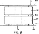
図9は、本発明の実施形態によるモールドチャンバ内の2個のプリフォームの配置を示す。下側プリフォーム47および上側プリフォーム48が下部モールド表面49および上部モールド表面50の間に重ねられている。モールド表面スペーサ51、52および53が、プリフォーム47および48とそれぞれの対応するモールド表面49および50の間に置かれている。スタックスペーサ52はプリフォームの間に入れられている。モールド表面スペーサ51、53の厚さは3.2mm(0.125インチ)ほどでよく、スタックスペーサの厚さは1.6mm(0.062インチ)ほどでよい。
【0061】
図10は、本発明による積み重ねられたプリフォームを通してのレジンあるいはピッチの流れを示す。レジンはゲート54からモールドに入り、プリフォームに一様に含浸されるように、プリフォーム55および56を通してまたそれらの周囲に均等に流れる。プリフォームから離れるピッチのフローラインはベントリング(示されていない)の方向に向かっている。
【0062】
RTM高密度化が他の、例えばCVD高密度化法より優れている点には、迅速な浸透、厚さ方向のより一様な密度、大きな内部多孔を充填(高密度化)できること、およびより大きな最終密度を達成できることが含まれる。本発明の装置および方法により、高粘度メソフェーズピッチを用いてプリフォームを効果的に高密度化することができる。
【0063】
ARメソフェーズピッチの粘度は、通常の市販のピッチ含浸剤、例えばA240より高い(含浸温度290℃までの温度で)。図11を参照。その粘度はA240に比べて高いが、それでもそれは、本発明を用いて、予熱されたプリフォームに完全に含浸させることができる程度には十分に低い(>1.5pa s)。ARの比較的高い粘度の付加的利益は、このピッチが<290℃の温度に冷却されると急速に固化するということである。このことにより、RTMプロセスによる部材の処理速度を上げることができる。ARに対する粘度対温度の曲線は、WhiteとGopalakrishanにより確認されたように、「加工範囲(processing window)」内にある(図12を参照)(J.L.White and M.K.Gopalakrishnan, Extended Abstracts of 20th Bienial Conference on Carbon,1991,184)。それが高粘度であることに加えて、ARピッチは、酸化により安定化されたとき炭素収率が大きい(すなわち、>85wt.%)。ARピッチを他のピッチ含浸剤から区別させるのはこれらの性質の組合せであり、本発明(すなわちRTM)ではこれら独特の性質の組合せが有効に利用される。
【0064】
レジンあるいはピッチにいくつかの成分、例えば、リン、ホウ素およびケイ素系化合物を加えることができる。これらの成分には、発泡剤、カーボン、グラファイト、セラミック、抗酸化剤、架橋剤、クレーおよびシリケートが含まれる。窒素ガスは典型的な発泡剤であり、他の発泡剤を用いてもよい。
【0065】
本発明の実施形態の装置および方法は、メソフェーズピッチなどの高粘度熱可塑性レジンを部材に浸透させる能力に関係する。背景技術では、低粘度熱硬化性レジンが通常使用された。プリフォームの多孔度は20〜70%でありうる。本発明の実施形態の方法には、多孔性プリフォームをモールドに入れること、その後で注入の前にモールドを脱気することが含まれる。注入中にモールドを真空引きしてもよい。別法として、真空は全く利用されなくてもよい。プリフォームを予熱してもモールド内で加熱してもよい。次に溶融ピッチがモールドに注入されてプリフォームを高密度化する。レジンはモールド内で冷却される。次に含浸されたプリフォームがモールドから取り出される。
【0066】
高密度化されたプリフォームを取り出しやすくするために、離型剤でモールドを処理してもよい。効果的な離型剤は、Huron Technologies,Inc.が市販するRelease Coating 854である。他の市販の離型剤も同様に有効でありうる。
【0067】
実施例3
図2に記載された注入モールディング装置を用いた。油圧プレスのクランプ能力は500トンである。アキュムレーターの理論的容積は13,880cm3(847立方インチ)であり、レジンを用いた実測容積は約13,601cm3(830立方インチ)である。ARピッチレジンで完全に充填されたとき、アキュムレーターは約16.8kg(37lb.)のレジンを収容する。押出機バレルの6箇所、押出機ヘッド、フローアダプタ、アキュムレーター・ヘッド、アキュムレーター、排出バルブ、排出パイプ、溶融体パイプ、ノズルブロック、ノズルエクステンションおよび供給口で押出機の温度を測定することができる。電気ヒーターで押出機は加熱され、モールドは高温オイル循環により加熱される。押出機スクリューにより溶融レジン内に圧力が生じ、この圧力はアキュムレーター内で維持される。
【0068】
部材をオーブンで350℃(707°F)に予熱し、浸透の直前にモールドキャビティに移した。注入の間、部材を融点より高く保つことにより、ピッチがプリフォーム全体に流れるようになる。このためにはまた、ピッチが小さい細孔に浸透できるように数分間圧力が維持されることを必要とする。この実施例では、Killion押出機を用いて実施された小スケール試験のシミュレーションとして、アキュムレーターを用いて溶融レジンを注入するのではなく、ピッチを直接モールドに押し出した。
【0069】
ARメソフェーズピッチの注入を、前もってCVDで200時間かけて高密度化した多孔性不織布繊維プリフォームで実施した。プリフォームの最初の寸法および重さは次の通りである:厚さ=2.2cm(0.875インチ)、ID=27.7cm(10.9インチ)、OD=47.2cm(18.6インチ)、重さ=3193g(7.04lb.)、密度=1.27g/cc(0.046lb/in3)。
温度プロフィール−Wilmington構造注入モールディング機:
供給側=
238℃(460°F) バレル
277℃(530°F) バレル
288℃(550°F) バレル
300℃(572°F) バレル
300℃(572°F) バレル
304℃(580°F) バレル
304℃(580°F) 押出機ヘッド
304℃(580°F) フローアダプタ
304℃(580°F) アキュムレーターヘッド
304℃(580°F) アキュムレーター
300℃(572°F) 排出バルブ
300℃(572°F) 排出パイプ
300℃(572°F) 溶融体パイプ
300℃(572°F) ノズルブロック
293℃(560°F) ノズルエクステンション
49℃(120°F) 供給口。
【0070】
レジンを予熱された部材に直接押し出した。注入の間、アキュムレーターでの背圧をモールドキャビティの圧力を維持するのに用いた。スクリューを30rpmで回転させ、13.1MPa(1900psi)の注入初期圧力が発生し、15分間の注入の最後に11.6MPa(1680psi)に低下した。モールドで、直径3.2mm(0.125インチ)のベント孔を用いた。高温オイル循環器を304℃(580°F)に設定した。プリフォームの最終重量は4196g(9.25lb.)であった。ARピッチを含浸させたプリフォームの最終密度は1.69g/cc(0.061lb/in3)であった。
【0071】
実施例4
図2および実施例3に記載される装置を用いた。ARメソフェーズピッチを、前もって1サイクルのCVDで高密度化した多孔性不織布繊維プリフォームに浸透させた。この多孔性プリフォームは航空機ブレーキディスクとして使用されるものの典型であり、次の寸法をもつ:50.55cm(19.90インチ)のOD、31.29cm(12.32インチ)のIDおよび2.22cm(0.875インチ)の厚さ。押出機の温度プロフィールは次の通りであった:
温度プロフィール
供給部=
238℃(460°F) バレル
277℃(530°F) バレル
296℃(565°F) バレル
300℃(572°F) バレル
300℃(572°F) バレル
302℃(576°F) バレル
302℃(576°F) 押出機ヘッド
302℃(576°F) フローアダプタ
302℃(576°F) アキュムレーターヘッド
302℃(576°F) アキュムレーター
300℃(572°F) 排出バルブ
300℃(572°F) 排出パイプ
300℃(572°F) 溶融体パイプ
285℃(545°F) ノズルブロック
285℃(545°F) ノズルエクステンション
49℃(120°F) 供給口。
【0072】
モールドの温度は293℃(560°F)であり、プリフォームを380℃(716°F)に予熱した。押出機スクリューを30rpmで回転させ、また13,604cc(830立方インチ)のアキュムレーターを満杯の47%まで満たした。アキュムレーターから18〜20秒で排出し、モールドおよびプリフォームに充填した。アキュムレーターの排出の終了近くで、最大圧力16.6Mpa(2400psi)に達した。図6に示されるように、1.6mm(0.062インチ)のベント孔がモールドの側面にあった。最初、ベント孔から揮発分が、後には溶融ピッチが排出された。浸透後、部材を10分間冷却してレジンを固化させモールドから取り出した。プリフォームの初期重量は3986g(8.77ポンド)、初期密度は1.39g/cc(0.050lb/in3)であった。浸透後、プリフォームの重量は4727g(10.40ポンド)、密度は1.72g/cc(0.062lb/in3)であった。浸透されたプリフォームを半分に切断した。プリフォームは、プリフォームの真中近くの小さな未浸透部分を除いて、よく充填されているように見えた。
【0073】
実施例5
複数のプリフォームの含浸を、図2および実施例3に記載される装置を用いて実施した。1サイクルのCVDを行った2個の不織布プリフォームに、ARピッチを用いて浸透させた。図9および10に示されるように、耐熱性ガスケット材の小片(2.54cm(1インチ)の円形)で部材を分離し、プリフォームの周囲をレジンが流れるようにして、この2個のプリフォームを互いに重ねた。プリフォームとモールド表面の間には、厚さ3.2mm(0.125インチ)のガスケット小片を用い、2個のプリフォームの間には、厚さ1.6mm(0.062インチ)のガスケットを用いた。
【0074】
押出機スクリューを30rpmで回転させ、アキュムレーターに満杯の90%まで充填した。アキュムレーターから約40秒で排出し、浸透の最後に18.96Mpa(2750psi)の最大圧力に達した。浸透されたプリフォームを10分間モールドで冷却して溶融レジンを固化させた。浸透前後のプリフォームの重量と密度は次の通りであった。
【0075】
【表1】

実施例6
米国特許(ハイブリッド発泡体特許)に記載されるもののようなカーボン発泡体の含浸を、図2および実施例3に記載される装置を用いて実施した。プリフォームを含むモールドに溶融ピッチレジンを直接押し出すことにより、発泡体プリフォームに浸透させた。発泡体プリフォームの嵩密度は、浸透前に0.89g/cc(0.032lb/in3)、浸透後に1.57g/cc(0.057lb/in3)であった。
【0077】
実施例7
米国特許(空気吹き込み特許)に記載されるもののような、PAN系チョップド炭素繊維および炭化メソフェーズピッチからなるプリフォームの含浸を、図2および実施例3に記載される装置を用いて実施した。
【0078】
押出機運転条件は次の通りであった:
238℃(460°F) バレル
277℃(530°F) バレル
293℃(560°F) バレル
300℃(572°F) バレル
302℃(576°F) バレル
304℃(580°F) バレル
304℃(580°F) 押出機ヘッド
304℃(580°F) フローアダプタ
304℃(580°F) アキュムレーターヘッド
304℃(580°F) アキュムレーター
300℃(572°F) 排出バルブ
302℃(576°F) 排出パイプ
304℃(580°F) 溶融体パイプ
304℃(580°F) ノズルブロック
296℃(565°F) ノズルエクステンション
49℃(120°F) 供給口。
【0079】
押し出しの前に、ARピッチレジンを、88℃(190°F)で約4時間Conairレジン充填/乾燥システムで乾燥させた。押出機スクリューを30rpmで回転させ、アキュムレーターに満杯の54%まで充填した。アキュムレーターから20〜22秒で排出し、浸透の最後に12.41Mpa(1800psi)の注入圧力に達した。
【0080】
プリフォームの寸法は、ODが46.79cm(18.42インチ)、IDが24.87cm(9.79インチ)、また厚さが3.07cm(1.21インチ)であった。出発重量と密度はそれぞれ、4305g(9.49ポンド)と1.14g/cc(0.041lb/in3)であった。RTM浸透後の重量と密度はそれぞれ、6023g(13.28ポンド)と1.59g/cc(0.057lb/in3)であった。
【0081】
実施例8
これまでの全ての実施例では、RTM浸透後にプリフォームを切断することにより、環状リングプリフォームの真中近くに小さな未浸透部分(ドライスポット)が見出された。このドライスポットは、モールドの存在により、レジンが全側面でプリフォームを包み込み、外側表面から中心に向かって浸透するようになるために起こると考えられる。高粘度ピッチでは、プリフォーム内に元々含まれていた空気はレジンを通リ抜けて部材の外部に逃げることができない。次の実施例では、プリフォームの周辺および内部のレジンの流れを制御することにより、ドライスポットをなくするために、図3に記載される配置形状をもつモールドを使用する。
【0082】
図2および実施例3に記載される装置を用いた。押出機温度プロフィールは次の通りであった:
供給部=
238℃(460°F) バレル
277℃(530°F) バレル
296℃(565°F) バレル
300℃(572°F) バレル
302℃(576°F) バレル
304℃(580°F) バレル
304℃(580°F) 押出機ヘッド
304℃(580°F) フローアダプタ
304℃(580°F) アキュムレーターヘッド
304℃(580°F) アキュムレーター
296℃(565°F) 排出バルブ
304℃(580°F) 排出パイプ
304℃(580°F) 溶融体パイプ
304℃(580°F) ノズルブロック
296℃(565°F) ノズルエクステンション
49℃(120°F) 供給口。
【0083】
押出機スクリューを20rpmで回転させた。モールドを230℃(450°F)に加熱した。浸透前に、プリフォームを空気循環オーブン中で400℃(752°F)に予熱した。モールドの表面を、シムにより1.2mm(0.040インチ)開いて、モールドのODで空気および揮発分のベントを可能にした。アキュムレーターに満杯の25%まで充填し、次に約20〜25秒かけてそれをモールド・キャビティに注入して含浸を実施した。次に浸透されたプリフォームを15分間モールド内で冷却してレジンを固化させ、取り出した。1サイクルのCVDを行った3個の不織布プリフォームに、これらの条件のもとに浸透させた。ディスクのIDは31.20cm(12.32インチ)であり、ODは50.5cm(19.90インチ)であった。浸透前後のデータが以下に示されている。
【0084】
【表2】
NO.1、2および3の場合に、モールド充填中に達したレジン圧力はそれぞれ、12.4MPa(1800psi)、9.7MPa(1400psi)および13.1MPa(1900psi)であった。浸透後に各部材を16個のほぼ等しいセグメントに分割した。如何なる未浸透部分も見出されなかった。従来の高密度化技術(例えば、CVD)より勝る、RTM浸透を用いることの主な利点は、部材内部の開孔が、CVDの薄い層により被覆されるのではなく、レジンにより完全に充填されるということである。しかし、カーボン/カーボンコンポジット最終製品を製造するときには、レジンを熱分解して含まれる全ての非カーボン元素を除去しなければならない。ARピッチなどの熱可塑性の高炭素収率レジンを浸透に用いる場合、熱分解には2つの選択肢がある。もしも浸透された部材を熱分解温度に単に加熱すれば、レジンは再溶融し、部材から滲出するであろう。選択肢の1つは、熱間等方圧加圧(HIP)を利用して熱分解することである。この方法では、部材を容器に入れなければならず、またこの装置は元来高価であり多くの安全措置を必要とする。もう1つの選択肢には、酸素含有雰囲気内でレジン浸透部材を、レジンの軟化点より低い、典型的には150℃(302°F)と240℃(464°F)の間の温度に加熱することが含まれる。酸素はレジンと反応し、特にレジンを架橋する。酸素がレジンと反応するので、酸素は材料に吸収され、その重量は増加する。レジンが適切な量の酸素を吸収すると、レジンを溶融させることなく、また部材内部から全くレジンを滲出させることなく、浸透された部材を熱分解温度まで昇温することができる。以下は、RTM浸透ディスクを安定化し炭化することに成功した例である。
【0086】
実施例9
6個の航空機ブレーキディスク不織布プリフォームを1サイクルのCVDで高密度化し、続いて実施例7および8に記載されるようにしてRTM浸透を実施した。浸透後の結果は次の通りである。
【0087】
【表3】
レジンによる浸透に続いて、空気循環オーブン中にディスクを170℃(338°F)で18日間置いた。安定化度を、部材内のレジン量に対する重量増加のパーセンテージを求めることにより評価した:
【0089】
【数1】
![]()
P=RTM浸透前のディスク重量
R=RTM浸透後のディスク重量
S=酸素による安定化後のディスク重量。
安定化後に、窒素雰囲気中で900℃(1652°F)の温度までディスクを炭化(熱分解)させた。安定化および炭化の結果は次の通りである。
【0091】
【表4】
900℃(1652°F)の温度まで炭化された後、ディスクには、加熱プロセスの間にディスク内部からレジンが滲出したような、目に見える形跡は全くなかった。ディスクから試料を取り偏光顕微鏡を用いて観察した。この方法を用いて、ディスクの厚さ方向の全体に渡って微細構造を特徴づけることができる。顕微鏡観察によってもやはりピッチ溶融の形跡は全くなかった。
【0093】
実施例10
1回のCVDおよび1回のRTM、酸化安定化および炭化サイクルを行った2個のディスクに、RTMを用いる2回目の浸透を実施した。モールドの構成、温度および注入パラメータは、この場合ショットの大きさが17%であったこと以外は実施例9のものと同一であった。2個のディスクの幾何学的寸法は次の通りであった:31.42cm(12.37インチ)のID、50.42cm(19.85インチ)のODおよび3.10cm(1.22インチ)の厚さ。これら2個の部材に対する結果が表5に示されている。
【0094】
【表5】
カーボン/カーボンコンポジットを製造するとき、例えば航空機ブレーキ・ディスクの製造では、高密度化プロセスは通常、CVDあるいはレジン浸透のいずれかを利用して3〜5回の浸透サイクルを必要とし、完了に数ヶ月かかる。CVD浸透サイクルを繰り返し用いる高密度化の不利な点は、処理しうる開孔の表面に層として熱分解カーボンが堆積するということである。浸透サイクルの間に、その表面の細孔が閉じてしまう傾向がある。結果として、ディスクはCVD釜から取り出され、内部多孔を開くためにその表面が機械加工される。合間の機械加工ステップの有効性は、CVD浸透の回数が増えるにつれて低下していく。
【0096】
実施例11
11個の不織布プリフォームに、1サイクルのCVD高密度化、実施例9に記載される1サイクルのRTM浸透および炭化処理を実施し、その後でCVD高密度化サイクルをさらに実施した。RTM前、炭化後および最終のCVDサイクル後のディスク密度が表6に示されている。
【0097】
【表6】
不織布プリフォームの製造中に、ファブリックの層を合わせて従来のテキスタイル加工技術を用いてニードルパンチした。このニードルパンチプロセスは、プリフォームの厚さ方向に貫かれたかなり大きく、幅が100〜200μmで深さが数百μmの孔を作り出す。航空機ブレーキ用のこれら不織布プリフォームを高密度化するのに用いられる従来のプロセスはCVDである。各CVDサイクルで、処理しうる全ての開孔表面に、厚さが2〜10μmの間の熱分解カーボン層が堆積する。ファブリック層内の繊維は非常に密集しており(1〜15μm離れている)、これらの部分は最初のCVDサイクルの間に非常に効果的に高密度化する。しかし、ニードルパンチにより生成した大きな孔は効果的に高密度化しない。高密度化前の繊維不織布プリフォームの密度は通常0.50g/cc(0.018lb/in3)である。表7に示されるデータは、表6に列挙されるものと同一寸法のディスクについて、1、2、3および4回のCVDサイクル後に測定された典型的な密度を列挙したものである。
【0099】
【表7】
表7に示されるように、密度の増加はCVDサイクルを重ねる毎に小さくなっている。これは、CVDで完全に充填されるようになるファブリック部分、ならびにCVDの層で被覆されているが、決して完全には充填されない大きな孔の結果である。RTMプロセスでは、ニードルパンチにより生じた大きな孔も含めて、処理しうる全ての開孔がカーボン前駆体レジンで完全に充填される。レジンが炭化するとき、コークス(炭化ピッチ)の密度は増加し、揮発分が除かれてそれに相当する重量損失がある(実施例9で示されるように、約85%の炭素収率)。密度の増加と重量損失により容積が全体として減少することになり、これが部材内に内部多孔を作り出す。炭化ピッチはニードルパンチにより生じた大きな孔を完全には充填しないが、後のCVD堆積のための内部表面をさらに生じつつ、それは全体の開孔容積を減少させる。表6のデータによって示されるように、全てCVD高密度化であるものに対してRTMおよびCVDの組合せでこれらの不織布プリフォームを高密度化することで、有意により大きい最終密度を達成することができる。
【0101】
プリフォームがメソフェーズ・ピッチ・レジンで浸透された後、次に、カーボン/カーボンコンポジット材料のカーボン・マトリックス部分を形成するカーボンに有機レジンを転化する処理をそれらに実施することができる。浸透されたディスクには、一般に酸化安定化と呼ばれるプロセスが実施される。ピッチは熱可塑性であり、もし材料を炭化するのに十分な温度まで加熱すれば、レジンは再溶融し、膨張し発泡するであろう。部材は、150℃と240℃の間の温度、典型的には170℃の空気循環オーブン中に入れられる。酸素がピッチと反応し、レジンを架橋し、それを本質的には熱硬化性に転化させる。このプロセスはピッチ系炭素繊維の製造に利用されている。このプロセスの完了は、酸素がピッチと反応し、それが吸収されて全体の重量が増加するので、質量増加により評価される。ピッチのみの重量増加で評価される場合(処理後部材重量−処理前部材重量)、酸素質量増加レベルは8.5%で十分である。8%と12%の間のOMG(oxygen mass gain、酸素質量増加)レベルをもつ部材は炭化に成功した。
【0102】
安定化の後に、不活性雰囲気の釜の中で650℃(1202°F)を超える温度に加熱することにより炭化することができる。炭化は典型的には900℃(1652°F)で実施される。炭化の後に、部材をさらなる加工の前に熱処理する(グラファイト化する)ことができるが、このステップはどうしても必要というわけではない。典型的な加熱処理温度は1600〜2500℃(2912〜4532°F)の範囲にあり、1800℃(3272°F)が好ましい。次に、前記実施例に示されるように、CVDあるいは高チャー収率、高粘度レジンによるRTMのいずれかを利用して、さらに部材を高密度化することができる。
【0103】
本明細書に示された前記の説明および具体的な実施形態は、本発明の最良の形態およびその原理の単なる例示であり、また当分野の技術者は、本発明の精神および範囲から逸脱することなくその装置および方法に変更および追加を容易になしうるということが理解され、したがって本発明の精神および範囲は添付の特許請求の範囲によってのみ限定されるということが理解される。
【図面の簡単な説明】
【図1】 図1aは、本発明に従って処理しうる繊維プリフォームの上面図である。
図1bは、本発明に従って処理しうる繊維プリフォームの側面図である。
【図2】 図2aは本発明の実施形態による押出レジンモールディング装置を示す図である。
図2bはモールディング装置の押出機の詳細を示す図である。
【図3】 プリフォームの周辺および内部でのレジンの流れの概略を含む、本発明の実施形態によるモールドの横断面を示す図である。
【図4】 プリフォームの周辺および内部でのレジンの流れの概略を含む、本発明の実施形態によるテーパ付きモールドチャンバの横断面を示す図である。
【図5】 本発明による図3および4の横断面に対応するモールドの上半部および下半部を示す図である。
【図6】 本発明によるモールドの下半部の別の実施形態を示す図である。
【図7】 本発明の実施形態によるモールドの側面図である。
【図8】 本発明の実施形態によるモールドの下半部に対する別のベント配置形態の上面図である。
【図9】 本発明の実施形態によるモールドキャビティ内における2個のプリフォームの相対的配置の側面図である。
【図10】 本発明の実施形態による積み重ねられたプリフォームを通してのレジンまたはピッチの流れの概略を示す図である。
【図11】 ARレジンの粘度と温度との関係を示すグラフである。
【図12】 ピッチ含浸に適する温度および粘度の範囲を示す図である。[0001]
(Technical field of the invention and industrial application)
The present invention is an improved process for rapidly densifying high temperature materials, including carbon-carbon (“C—C”) composites and porous preforms, with high viscosity resins or pitches using resin transport molding technology. About.
[0002]
(Background of the Invention)
The present invention describes an improved process for rapid densification of high temperature materials including CC composites, carbon and ceramic fiber reinforced preforms and carbon and ceramic foams.
[0003]
Typically, these high temperature materials include carbon and / or ceramic CVD / CVI (Chemical Vapor Infiltration), or liquid infiltration using resin and / or pitch, and these It is densified using a combination of This CVD / CVI process is very capital intensive, with multiple densification cycles usually requiring weeks to complete and the long cycle time.
[0004]
The impregnation of the resin and pitch into the porous body usually includes vacuum / pressure impregnation (VPI). In the VPI process, a large amount of resin or pitch is melted in one container and the porous preform is contained in a second container under vacuum. Molten resin or pitch is transferred from container 1 to a porous preform in a second container using a combination of vacuum and pressure. The VPI process is limited to using resins and pitches with low viscosity and concomitantly low carbon yield. Thus, densification of porous preforms with liquid resin and pitch precursors utilizing the VIP process usually requires several cycles of impregnation followed by carbonization (often up to 7 cycles) to achieve the desired final density. It takes a long cycle time to reach several weeks to achieve.
[0005]
In a typical VPI process, high pressure impregnation / carbonization (PIC) is used to increase the carbon yield of the pitch to avoid the long cycle times associated with using low char yield resin and pitch. Used for A typical high pressure carbonization cycle is over 34.5 MPa (5000 psi) and often over 103 MPa (15000 psi). Due to the high char yield resulting from high pressure carbonization, the number of densification cycles can be reduced from 6-7 cycles to 3-4 cycles in order to achieve comparable densities. However, high-pressure containers are capital intensive and limited in size, limiting the number of preforms that can be densified in a single container. The high pressures used also increase the risk of explosion and special safety measures are required to meet safety standards.
[0006]
Another approach to increasing the efficiency of the carbon densification process involves the use of a high carbon yield (> 80%) liquid resin. Typical high char yield resins include synthetic mesophase pitch (eg, AR mesophase pitch from Mitsubishi Gas Chemical Company, catalytically polymerized naphthalene), and thermally or chemically treated coal tar. And petroleum-derived pitch and other thermoplastic resins. However, there are many problems associated with using these high char yield resins in current VPI processes in connection with their high viscosity and concomitantly high process temperatures.
[0007]
The present invention provides a solution to the above problem and provides a method by which higher density composites can be obtained with shorter cycle times. The present invention utilizes resin transport molding (RTM) technology in combination with high char yield resin to densify the porous preform within minutes.
[0008]
The RTM process is not new. Recently, resin transport molding, or RTM, and its derivatives (also referred to as resin injection molding) have been used in the aerospace, automotive, and munitions industries as a means of densifying porous preforms. It has become popular. In fact, RTM was originally introduced in the middle of the 1940s, but it had little commercial success until the 1960s and 1970s when it was used to make goods such as bathtubs, computer keyboards and fertilizer hoppers. .
[0009]
RTM is typically used to produce polymer-based composites. A fiber preform or mat is placed in a mold that matches the desired part shape. Typically, a relatively low viscosity thermosetting resin is injected into the porous body in the mold at low temperature (38-149 ° C. (100-300 ° F.)) using pressure or induced under vacuum. . The resin is cured in the mold before it is removed from the mold.
[0010]
RTM demands the low cost and high annual total (approximately 500-50,000) parts of the automotive industry, as well as the higher performance / low annual total (almost 50-5,000) parts of the aerospace industry. It has been shown to have a unique performance to satisfy. By modifying the RTM process, it becomes well suited for the manufacture of large and complex thick cross-section structures for infrastructure and military applications. One example of this is the lower body of a Composite Armored Vehicle (CAV) body. The automotive industry has been using RTM for decades.
[0011]
US Pat. No. 5,770,127 describes a method for producing carbon or graphite reinforced composites. A rigid carbon foam preform is placed in a sealed flexible bag. Vacuum the bag. A matrix resin is placed in the bag through the inlet valve and impregnated into the preform. Next, the preform is cured by heating. The resulting carbon or graphite structure is then removed from the bag.
[0012]
U.S. Pat. No. 5,306,448 discloses a resin transport molding method that utilizes a reservoir. This reservoir comprises a porous sponge that deforms in response to pressure, containing a resin about 2 to 10 times the weight of the sponge. The resin reservoir facilitates resin transport molding by providing a resin reservoir that can be reliably and desirably impregnated into a porous preform such as a porous fiber reinforced composite.
[0013]
U.S. Pat. No. 5,654,059 discloses making a thick three-dimensional mat structure comprising discontinuous thermoset pitch fibers with needle punched openings in at least 80% of the entire structure.
[0014]
U.S. Pat. No. 4,986,943 discloses a method for oxidative stabilization of a pitch matrix of a carbon-carbon composite. In this method, a carbon fiber lattice is impregnated with a pitch-based matrix precursor, oxidized in an oxygen-containing atmosphere at a temperature below the pitch softening temperature, and carbonized to convert the matrix material into coke.
[0015]
In a typical extrusion process for resins and plastics, the viscous melt is extruded through a forming die as a continuous stream under pressure. The feedstock can be charged to the apparatus in a molten state, but more commonly it consists of solid particles that must be melted, mixed, and pressurized in an extruder. This solid material can be in the form of pellets, powder, beads, flakes or reground material. The components may be premixed or supplied separately through one or more supply ports.
[0016]
Most extruders incorporate a single screw that rotates in a horizontal cylinder barrel and is equipped on the input and discharge sides (weighing side) installed on one end (feed side). Has a forming die. A series of heaters are arranged to divide the extruder into separate heating zones, usually along the length of the barrel. In typical extrusion applications, forming dies are used to form fibers, rods or other shapes. In the RTM process, the forming die is usually replaced with a mold containing a porous body or preform.
[0017]
Twin screw extruders are used less frequently than single screw extruders, but they are used for difficult to compound applications, for devolatilization, and for extruding materials with high viscosity and poor thermal stability. Widely used in The design of the biaxial screw can be either different direction rotation or same direction rotation, and the screw can be fully meshed, partially meshed or non-meshed. Extrusion techniques known in the art are described in Concise Encyclopedia of Polymer Science and Engineering, Jaqueline I., et al. Kroschwitz, Ed. John Wiley & Sons, 1990, p. 363-367; and Principles and Plasticating Extraction, Z. Tadmore and I. Klein, Van Nostrand Reinhold, New York, 1970.
[0018]
The use of high char yield resins may increase the carbon yield and reduce the number of densification cycles required to achieve the target density, but using them for VPI and RTM processes Was not successful. The use of high char yield resins in VPI processes is limited because high char yield resins are highly viscous and require higher temperatures to reduce resin and pitch viscosities for impregnation. It was. The relatively high processing temperature and relatively high viscosity of the high char yield yield resin creates the following problems with existing VPI and RTM processes.
[0019]
1) The resin begins to cure in the holding container before impregnation.
2) Higher pressure is required to impregnate the high viscosity resin.
3) When the resin penetrates into the porous body or preform non-uniformly and imperfectly, air pockets are sealed in the preform and dry spots (porous) are generated.
[0020]
Successful use of high char yield resins in the RTM process reduces the number of impregnation cycles to achieve the required target density, resulting in a composite material compared to existing CVD / CVI and VPI processes. Densification cycle time will be significantly reduced. In addition, using a high char yield resin in the RTM process could also reduce resin waste (90% utilization of the resin).
[0021]
To succeed using high char yield resins in the RTM process, several innovations are required, including:
1) Means for efficiently and uniformly flowing a high-viscosity resin into a preform and throughout the preform.
[0022]
2) A means of maximizing the efficiency of densification by preventing the formation of dry pockets resulting from the combination of incomplete impregnation of the resin and trapping of air and volatiles in the preform.
[0023]
The prior art shows that there is a need for a method and apparatus for impregnating a porous preform with a high viscosity molten resin (eg, AR mesophase pitch) at high temperatures. The resulting impregnated preform is preferably free of “dry spots” and can be subjected to further processing such as oxidation stabilization, carbonization and graphitization.
[0024]
(Summary of Invention)
The present invention, in part, provides rapid, individual penetration into a porous fiber preform or rigid porous body using a high viscosity, high char yield resin (eg, mesophase pitch).
[0025]
The present invention, in part, provides an apparatus and method that utilizes a high viscosity mesophase pitch to densify rigid bodies.
The present invention also provides, in part, an extruder or similar device for uniformly melt mixing the injection medium (high viscosity resin). The extruder may be either a single screw or twin screw extruder. A single screw extruder is preferred because it is less expensive.
[0026]
The present invention also includes, in part, an extruder that can be equipped with an accumulator that holds a controlled volume of molten resin before being injected into the mold under pressure. provide. An advantage of the present invention is that it provides a resin transport molding method that eliminates resin waste.
[0027]
The present invention also provides, in part, a hydraulic press that restrains a porous preform or a mold containing a rigid porous body.
The present invention also provides, in part, a mold that efficiently distributes the resin uniformly throughout the preform.
[0028]
The present invention relates in part to a mold that can be placed horizontally in a press. A gate with a nozzle can be placed in the center of the surface of the mold half. The mold cavity may be tapered to make the molten resin flow more appropriate.
[0029]
The invention also includes, in part, placing a porous preform in the mold; injecting a molten resin or pitch into the mold; cooling the resin or pitch below the melting point; and impregnating the preform The mold is disposed in the upper half; the lower half opposite the upper half so that the upper and lower halves form a mold cavity; At least one gate; a valve through which the resin can pass through the gate; and equipment for venting and / or evacuating the mold.
[0030]
The porous body can be a fiber preform, a carbon or ceramic fiber preform, a non-woven preform, a rigid fiber preform, a carbon or ceramic porous body, or a foam preform or a rigid foam preform. This preform can be carbonized or graphitized. It is also possible to infiltrate the preform using CVD / CVI. It may be a preform that has been impregnated with a resin. The preform can be heated to a temperature between about 290-425 ° C. (554-797 ° F.) either before or after being placed into the mold. The preform can be heated to a temperature exceeding the melting point of the resin or pitch. The mold is heated to a temperature between about 138-310 ° C (280-590 ° F). The resin or pitch can be a synthetic pitch, coal tar pitch, petroleum pitch, mesophase pitch, coal tar derivatives such as high char yield thermosetting resins, petroleum or synthetic pitch precursors or combinations thereof. Multiple members can be loaded into a single mold.
[0031]
Furthermore, according to a part of the present invention, after densification, the thermoplastic resin can be effectively cross-linked by treating the densified member at a high temperature in an oxygen-containing atmosphere. This process is similar to the process carried out in the production of pitch-based carbon fibers, fixing the matrix in place in the preform and softening the matrix during subsequent heating at a temperature above the melting point of the resin, Prevents being inflated and eliminated. This oxygen stabilization is typically performed in the presence of oxygen at a temperature that does not exceed the softening point of the resin (150-250 ° C. (302-482 ° F.)), typically 170 ° C. (338 ° With heating to ° F). Further processing of the densified member includes carbonization, graphitization, and reimpregnation using RTM or CVD / CVI.
[0032]
The objects, features and advantages of the present invention will become more fully apparent from the following detailed description of the preferred embodiments, the appended claims and the accompanying drawings. The present invention will be understood more fully by the following detailed description and by way of example only, and thus by the accompanying drawings, which do not limit the invention. Each drawing is not drawn to scale.
[0033]
(Description of Preferred Embodiment)
Rapid densification methods for porous bodies or preforms (eg, carbon fiber reinforced preforms or rigid porous preforms) include high carbon yield, high viscosity resin, single or multiple infiltration and carbonization Steps are included. The permeation medium can be coal tar pitch, petroleum pitch, mesophase pitch, high char yield thermosetting resin, or mixtures thereof. The characteristics of the process according to the present invention (and also for a normal RTM), alone or in combination, include:
a) Use of a high melting point, high viscosity pitch or resin,
b) High char yield Char yield Use of pitch or resin,
c) use of an extruder for online melting and mixing;
d) use of relatively thick members;
e) use of carbon foam preforms,
f) use of a rigid porous body;
g) Achieving rapid penetration into the component (on the order of seconds),
h) Use of lower mold temperature due to rapid penetration,
i) Foaming pitch or resin saturants into the RTM to facilitate CVD / CVI and improve thermal properties, or to create additional surface parts to modify the surface part,
j) having a flow structure when infiltrating liquid crystals such as mesophase pitch, and
k) The ability to mix other materials into the molten resin prior to infiltration.
[0034]
The following examples describe the use of extrusion, accumulator and molding techniques combined to provide special equipment and processes for densifying porous bodies with high viscosity, high char yield resins.
[0035]
For the purposes of this application, the resin contains a thermoplastic or thermosetting liquid precursor containing, for example, phenol, furfuryl, and pitch, petroleum, synthetic, heat treatment and catalytic conversion pitch, mesophase pitch derived from coal tar. Including pitch, and even Commodore Technologies, Inc. Is defined as a preceramic polymer such as the commercially available Ceraset®.
[0036]
For purposes of this application, a mold is defined as a container in which a porous body or preform is placed and resin penetration occurs.
In the first two examples, a small porous fiber preform similar to that used in aircraft brake applications was densified using a high char yield resin. FIGS. 1a and 1b show top and side views of the fiber preform used in these examples. The diameter of such a preform 1 is about 12.7 cm (5 inches). In the center of the preform 1 is a
[0037]
The first experiment was an extruder fitted with an aluminum mold with a small vent hole, such as a 0.79 mm (0.031 inch) die orifice, that could vent entrapped air and volatiles from the preform during impregnation, This was carried out using a Killion extruder. This orifice is designed to maintain a back pressure on the mold at a predetermined rpm of the extruder, so that the mold can be pressurized to allow the resin to uniformly penetrate the porous preform. The pitch powder or pellets were fed to a single screw extruder. The extruder was equipped with a heating zone along the barrel. The resin (AR pitch) was melted in an extruder before being extruded directly into a heated mold.
[0038]
Example 1
A Killion extruder with 5 heating zones along the barrel and a length to diameter ratio of 35: 1 was connected directly to the aluminum mold. The temperature profile of the extruder was as follows:
Supply section = 240 ° C (464 ° F) Zone 1
278 ° C (532 ° F)
310 ° C (590 ° F)
305 ° C (581 ° F)
300 ° C (572 ° F)
305 ° C (581 ° F) Die Zone
300 ° C. (572 ° F.) mold.
The fiber preform was preheated in the mold for 2 hours prior to infiltration until the internal temperature reached 285 ° C. (545 ° F.). The extruder screw was initially operated at 20 rpm and was reduced to 15 rpm during operation. The AR pitch resin was charged from the hopper into the extruder and extruded into a porous fiber preform at a melt pressure of 5.52-6.21 MPa (800-900 psi) over 2 hours. The actual melt resin temperature was measured using a thermocouple installed in the melt stream. The temperature of the melt during infiltration is between 318 ° C and 321 ° C (604-610 ° F) and is higher than the set temperature of the extruder due to the additional shear energy applied to the melt by the extruder screw . The extruder screws were turned on and off throughout the 2 hour run so that the melt pressure was maintained between 5.52 and 6.21 MPa (800-900 psi). Approximately 10 to 15 minutes later, a resin exiting the 0.79 mm (1/32 inch) vent hole located on the side of the mold was observed.
[0039]
After 2 hours, the mold was cooled and the heat source was shut off. About 30 minutes after the heating was stopped, the mold was opened and the member was taken out. After removal, the member was cut in half and visually inspected. The part was almost completely filled with resin, but there was actually a small dry area with some signs of delamination between fabric layers.
[0040]
Although the porous preform was successfully impregnated with a high viscosity resin, several improvements were noted including the following:
1) Reduction of impregnation time
2) Reduce the size of the dry area
3) Eliminate the tendency of the members to delaminate.
[0041]
An RTM densification process for densifying a porous fiber preform that has become rigid by CVD is shown in Example 2. In order to reinforce the porous preform and reduce the tendency of the porous preform to delaminate, the preform was stiffened by CVD.
[0042]
Example 2
Before the resin was infiltrated, in order to stiffen the member, the porous nonwoven fabric preform was carbonized and subjected to one cycle of CVD densification.
[0043]
The Killion extruder / mold system described in Example 1 was used. A CVD stiffened fiber preform with a diameter of 12.7 cm (5 inches) and a thickness of 2.54 cm (1 inch), with a 1.27 cm (0.5 inch) hole drilled in the center, Cut from full size aircraft brake disc preform (see FIGS. 1 and 2). The aluminum mold had a vent hole of 1.32 mm (0.052 inches), a diameter of 15.24 cm (6 inches), and a thickness of 2.54 cm (1 inch). Larger vent holes were used to allow the resin (AR pitch) to escape from the mold while the extruder was running throughout the entire infiltration process. The objective was to keep the screw turning, maintain a constant pressure, seal with melt along the screw, and reduce the total operating time from 2 hours to 15 minutes. Extruder settings are described below:
Supply section = 240 ° C (464 ° F) Zone 1
278 ° C (532 ° F)
310 ° C (590 ° F)
310 ° C (590 ° F)
305 ° C (581 ° F)
305 ° C (581 ° F) die
305 ° C (581 ° F) die (additional special die controller)
305 ° C (581 ° F) mold.
[0044]
Before starting the extruder, the member to be infiltrated was heated again in the mold for 2 hours. Resin (AR mesophase pitch) was fed from the hopper to the extruder. The resin was extruded for 15 minutes until it was observed that the resin emerged from the vent hole. The mold was then cooled for 20 minutes. During infiltration, the pressure dropped from the original 5.86 MPa (850 psi) to 1.79 MPa (260 psi) due to leakage of the mold flange gasket.
[0045]
The initial weight of the preform before penetration was 369.7 g (0.815 lb), and the final weight was 447.6 g (0.987 lb), an increase of 77.9 g (0.172 lb). The initial density is 1.34 g / cc (0.048 lb / in Three The final density is 1.63 g / cc (0.059 lb / in). Three )Met. The infiltrated preform was cut in half and completely filled except for one small dry area. The dry area may have occurred due to mold gasket leakage and the resulting decrease in osmotic pressure. However, the CVD stiffened preform densified using a high viscosity resin (AR mesophase pitch) showed no signs of delamination. Results from the first attempt at resin transport molding showed that the resin molding process can be used to achieve penetration of high viscosity, high char yield resin (AR mesophase pitch) into fiber preforms. . In the following description and the following examples, larger preform impregnations typical of those used in aircraft braking applications are illustrated using the process and apparatus of the present invention.
[0046]
FIG. 2a shows the resin transport molding apparatus of the present invention. FIG. 2b shows the extruder in more detail. Raw materials, typically AR mesophase pitch resin, commercially available from Mitsubishi Gas Chemical Co., Ltd., is fed to a
[0047]
The member to be infiltrated is preheated to a temperature equal to or higher than the melting temperature of the resin in the oven or the mold cavity. The mold is contained or placed in the press 12. The press 12 may be a hydraulic press. Although a vertically moving press is depicted in FIG. 2, a horizontally moving press could also be used. Also, the mold need not be completely in the press. The clamping force of the press 12 depends on the size of the member used (in the example given, a 500 ton press was used) and counters the pressure of the resin being pushed into the mold cavity. The
[0048]
One method of process operation includes degassing the mold before and / or during infiltration. This method requires that the mold be sealed fairly well and maintain a vacuum. However, the use of vacuum requires extra complexity and cost. Preferred methods include the mold design shown in FIGS. The basic principle of these designs is that the resin flows freely around the porous preform or the inner diameter (ID) of the disk, the top and bottom.
[0049]
FIG. 3 shows a cross section of a mold according to an embodiment of the present invention. An
[0050]
FIG. 4 illustrates a cross section of a mold having a tapered chamber according to an embodiment of the present invention. The
[0051]
3 and 4 depict a mold having only one chamber. Alternatively, the mold chamber could be designed to hold a number of porous bodies. A cavity (or chamber) represents a compromise between various conflicting design considerations whose relative priorities vary with application.
[0052]
Venting is also performed through the mold surface. FIG. 5 is an illustration of the upper and lower halves of a single chamber, annular mold of an embodiment of the present invention. In the lower half of the mold there are
[0053]
Venting is performed while the resin is being injected into the mold. Alternatively, the mold can be evacuated prior to resin injection. The mold can also be evacuated during resin injection.
[0054]
FIG. 6 shows a top view of the lower half of the mold according to an embodiment of the invention. The
[0055]
FIG. 7 is a side view of a mold according to an embodiment of the present invention. The lower half 41 of the mold is combined with the
[0056]
FIG. 8 is a top view of another vent arrangement in the lower half of the mold according to an embodiment of the present invention. The vent holes 43a, 43b, 43c and 43d are led to the
[0057]
As shown in FIG. 8, further changes were made to help keep the pressure in the mold chamber uniform throughout the infiltration process and prevent the melt pitch from entering the vent holes. This added feature includes drilling holes in the vent holes (inlet at vent ring 46) 43a, 43b, 43c and 43d, and inserting inserts with small orifices to create a pressure drop. It was included. This facilitates cavity pressure control (uniform during injection) and solidifies the melt pitch (the
[0058]
The present invention achieves densification of the preform using the molten pitch by pitch extrusion and injection. However, an additional advantage can be recognized in view of the fact that using an injection unit to equalize pressure and extruding and injecting pitch into molds and preforms is a very fast process. Injection into the preform occurs very quickly in less than a minute to several seconds depending on the size of the preform. The injection process is fast enough to achieve much lower mold temperatures, even temperatures below the melting point of the resin. However, the porous preform must be preheated to a temperature above the pitch softening point so that the molten resin can flow into the preform under pressure. For industrial efficiency, it is required to complete this process quickly. Proper control of pressure generation accelerates the infiltration process.
[0059]
With proper pressure control, the preform can be impregnated more quickly without generating extreme forces in the mold cavity that can cause the press to open during the impregnation process. Taking into account the area of the mold chamber and the applied tonnage (eg, 500 tons), the mold opens when the force in the mold chamber exceeds the applied clamping tonnage. The melt pressure during the impregnation process would be, for example, less than 21 MPa (3000 psi) in an aircraft brake disk preform mold. This pressure is controlled by a hydraulic system and mold vent as shown in FIGS.
[0060]
FIG. 9 shows the arrangement of two preforms in a mold chamber according to an embodiment of the present invention. A
[0061]
FIG. 10 shows the resin or pitch flow through the stacked preforms according to the present invention. The resin enters the mold from
[0062]
The advantages of RTM densification over other, eg, CVD densification methods include rapid penetration, more uniform density in the thickness direction, the ability to fill (dense) large internal pores, and more This includes the ability to achieve large final densities. The apparatus and method of the present invention can effectively densify the preform using a high viscosity mesophase pitch.
[0063]
The viscosity of the AR mesophase pitch is higher than normal commercial pitch impregnants, such as A240 (at temperatures up to 290 ° C. impregnation). See FIG. Its viscosity is high compared to A240, but it is still low enough (> 1.5 pas) that it can be fully impregnated into a preheated preform using the present invention. An additional benefit of the relatively high viscosity of AR is that this pitch solidifies rapidly when cooled to a temperature of <290 ° C. Thereby, the processing speed of the member by the RTM process can be increased. The viscosity vs. temperature curve for AR is within the “processing window” (see FIG. 12), as confirmed by White and Gopalakrishan (see JL White and MK Gopalakrishnan, Extended). Abstracts of 20 th Bienial Conference on Carbon, 1991, 184). In addition to its high viscosity, AR pitch has a high carbon yield (ie,> 85 wt.%) When stabilized by oxidation. It is the combination of these properties that differentiates AR pitch from other pitch impregnants, and the unique combination of properties is effectively utilized in the present invention (ie, RTM).
[0064]
Several components such as phosphorus, boron and silicon-based compounds can be added to the resin or pitch. These components include blowing agents, carbon, graphite, ceramics, antioxidants, crosslinkers, clays and silicates. Nitrogen gas is a typical blowing agent, and other blowing agents may be used.
[0065]
The apparatus and method of embodiments of the present invention relate to the ability to infiltrate a member with a high viscosity thermoplastic resin such as mesophase pitch. In the background art, low viscosity thermosetting resins are usually used. The porosity of the preform can be 20-70%. The method of embodiments of the present invention includes placing a porous preform into a mold and then degassing the mold prior to injection. The mold may be evacuated during injection. Alternatively, no vacuum may be used at all. The preform may be preheated or heated in the mold. Next, a molten pitch is injected into the mold to densify the preform. The resin is cooled in the mold. The impregnated preform is then removed from the mold.
[0066]
In order to make it easy to take out the preform having a higher density, the mold may be treated with a release agent. Effective mold release agents are described by Huron Technologies, Inc. Is Release Coating 854 available on the market. Other commercially available mold release agents may be effective as well.
[0067]
Example 3
The injection molding apparatus described in FIG. 2 was used. The clamping capacity of the hydraulic press is 500 tons. The theoretical volume of the accumulator is 13,880cm Three (847 cubic inches) and the measured volume using the resin is about 13,601 cm. Three (830 cubic inches). When fully filled with the AR pitch resin, the accumulator contains about 16.8 kg (37 lb.) of resin. Extruder temperature can be measured at 6 locations on the extruder barrel, extruder head, flow adapter, accumulator head, accumulator, discharge valve, discharge pipe, melt pipe, nozzle block, nozzle extension and supply port it can. The extruder is heated by an electric heater, and the mold is heated by high temperature oil circulation. The extruder screw creates pressure in the molten resin and this pressure is maintained in the accumulator.
[0068]
The part was preheated to 350 ° C. (707 ° F.) in an oven and transferred to the mold cavity just prior to infiltration. By keeping the member above the melting point during pouring, the pitch will flow throughout the preform. This also requires that the pressure be maintained for a few minutes so that the pitch can penetrate the small pores. In this example, as a simulation of a small scale test performed using a Killion extruder, the pitch was extruded directly into the mold rather than injecting molten resin using an accumulator.
[0069]
AR mesophase pitch injection was performed on porous nonwoven fiber preforms that had been densified beforehand by CVD for 200 hours. The initial dimensions and weight of the preform are as follows: Thickness = 2.2 cm (0.875 inch), ID = 27.7 cm (10.9 inch), OD = 47.2 cm (18.6) Inch), weight = 3193 g (7.04 lb.), density = 1.27 g / cc (0.046 lb / in) Three ).
Temperature profile-Wilmington structure injection molding machine:
Supply side =
238 ° C (460 ° F) barrel
277 ° C (530 ° F) barrel
288 ° C (550 ° F) barrel
300 ° C (572 ° F) barrel
300 ° C (572 ° F) barrel
304 ° C (580 ° F) barrel
304 ° C (580 ° F) Extruder head
304 ° C (580 ° F) Flow adapter
304 ° C (580 ° F) Accumulator head
304 ° C (580 ° F) Accumulator
300 ° C (572 ° F) discharge valve
300 ° C (572 ° F) discharge pipe
300 ° C (572 ° F) melt pipe
300 ° C (572 ° F) nozzle block
293 ° C (560 ° F) nozzle extension
49 ° C (120 ° F) supply port.
[0070]
The resin was extruded directly onto the preheated member. During injection, back pressure in the accumulator was used to maintain the pressure in the mold cavity. The screw was rotated at 30 rpm and an initial injection pressure of 13.1 MPa (1900 psi) was generated and dropped to 11.6 MPa (1680 psi) at the end of the 15 minute injection. A vent hole with a diameter of 3.2 mm (0.125 inch) was used in the mold. The hot oil circulator was set at 304 ° C. (580 ° F.). The final weight of the preform was 4196 g (9.25 lb.). The final density of the preform impregnated with AR pitch was 1.69 g / cc (0.061 lb / in). Three )Met.
[0071]
Example 4
The apparatus described in FIG. 2 and Example 3 was used. The AR mesophase pitch was infiltrated into a porous nonwoven fiber preform that had previously been densified by one cycle of CVD. This porous preform is typical of those used as aircraft brake discs and has the following dimensions: 50.55 cm (19.90 inch) OD, 31.29 cm (12.32 inch) ID and 2. 22 cm (0.875 inch) thick. The temperature profile of the extruder was as follows:
Temperature profile
Supply section =
238 ° C (460 ° F) barrel
277 ° C (530 ° F) barrel
296 ° C (565 ° F) barrel
300 ° C (572 ° F) barrel
300 ° C (572 ° F) barrel
302 ° C (576 ° F) barrel
302 ° C (576 ° F) Extruder head
302 ° C (576 ° F) flow adapter
302 ° C (576 ° F) Accumulator head
302 ° C (576 ° F) Accumulator
300 ° C (572 ° F) discharge valve
300 ° C (572 ° F) discharge pipe
300 ° C (572 ° F) melt pipe
285 ° C (545 ° F) nozzle block
285 ° C (545 ° F) nozzle extension
49 ° C (120 ° F) supply port.
[0072]
The mold temperature was 293 ° C. (560 ° F.) and the preform was preheated to 380 ° C. (716 ° F.). The extruder screw was rotated at 30 rpm and a 13,604 cc (830 cubic inch) accumulator was filled to 47% full. The product was discharged from the accumulator in 18 to 20 seconds, and filled into a mold and a preform. Near the end of the discharge of the accumulator, a maximum pressure of 16.6 Mpa (2400 psi) was reached. As shown in FIG. 6, there was a 1.6 mm (0.062 inch) vent hole on the side of the mold. Initially, volatiles were discharged from the vent holes, and later the molten pitch was discharged. After penetration, the member was cooled for 10 minutes to solidify the resin and removed from the mold. The initial weight of the preform is 3986 g (8.77 lb) and the initial density is 1.39 g / cc (0.050 lb / in). Three )Met. After infiltration, the preform weighed 4727 g (10.40 pounds) and the density was 1.72 g / cc (0.062 lb / in). Three )Met. The infiltrated preform was cut in half. The preform appeared to be well filled except for a small unpermeated portion near the middle of the preform.
[0073]
Example 5
Impregnation of multiple preforms was performed using the apparatus described in FIG. 2 and Example 3. Two nonwoven fabric preforms subjected to one cycle of CVD were infiltrated using an AR pitch. As shown in FIGS. 9 and 10, the two parts are separated by a piece of heat-resistant gasket material (2.54 cm (1 inch) circle) and the resin flows around the preform. The reforms were stacked on top of each other. A 3.2 mm (0.125 inch) thick gasket piece is used between the preform and the mold surface, and a 1.6 mm (0.062 inch) thick gasket is used between the two preforms. Was used.
[0074]
The extruder screw was rotated at 30 rpm and the accumulator was filled to 90% full. The accumulator was drained in about 40 seconds, and a maximum pressure of 18.96 Mpa (2750 psi) was reached at the end of infiltration. The infiltrated preform was cooled with a mold for 10 minutes to solidify the molten resin. The weight and density of the preform before and after infiltration were as follows.
[0075]
[Table 1]
Example 6
Carbon foam impregnation, such as that described in the US patent (hybrid foam patent), was performed using the apparatus described in FIG. 2 and Example 3. The foam preform was infiltrated by extruding the molten pitch resin directly into a mold containing the preform. The bulk density of the foam preform is 0.89 g / cc (0.032 lb / in) before penetration. Three ), 1.57 g / cc (0.057 lb / in) after infiltration Three )Met.
[0077]
Example 7
Impregnation of a preform consisting of PAN-based chopped carbon fiber and carbonized mesophase pitch, such as that described in the US patent (air blown patent), was performed using the apparatus described in FIG. 2 and Example 3.
[0078]
Extruder operating conditions were as follows:
238 ° C (460 ° F) barrel
277 ° C (530 ° F) barrel
293 ° C (560 ° F) barrel
300 ° C (572 ° F) barrel
302 ° C (576 ° F) barrel
304 ° C (580 ° F) barrel
304 ° C (580 ° F) Extruder head
304 ° C (580 ° F) Flow adapter
304 ° C (580 ° F) Accumulator head
304 ° C (580 ° F) Accumulator
300 ° C (572 ° F) discharge valve
302 ° C (576 ° F) discharge pipe
304 ° C (580 ° F) Melt pipe
304 ° C (580 ° F) Nozzle block
296 ° C (565 ° F) Nozzle extension
49 ° C (120 ° F) supply port.
[0079]
Prior to extrusion, the AR pitch resin was dried in a Conair resin filling / drying system at 88 ° C. (190 ° F.) for about 4 hours. The extruder screw was rotated at 30 rpm and the accumulator was filled to 54% full. The accumulator was drained in 20-22 seconds and an injection pressure of 12.41 Mpa (1800 psi) was reached at the end of infiltration.
[0080]
The preform dimensions were OD 46.79 cm (18.42 inches), ID 24.87 cm (9.79 inches), and thickness 3.07 cm (1.21 inches). Starting weight and density are 4305 g (9.49 lb) and 1.14 g / cc (0.041 lb / in, respectively). Three )Met. The weight and density after RTM penetration were 6023 g (13.28 lbs) and 1.59 g / cc (0.057 lb / in, respectively). Three )Met.
[0081]
Example 8
In all the examples so far, a small unpermeated portion (dry spot) was found near the middle of the annular ring preform by cutting the preform after RTM infiltration. This dry spot is thought to occur because the presence of the mold causes the resin to wrap the preform on all sides and penetrate from the outer surface toward the center. At a high viscosity pitch, the air originally contained in the preform cannot pass through the resin and escape to the outside of the member. In the following example, a mold having the configuration described in FIG. 3 is used to eliminate dry spots by controlling the resin flow around and within the preform.
[0082]
The apparatus described in FIG. 2 and Example 3 was used. The extruder temperature profile was as follows:
Supply section =
238 ° C (460 ° F) barrel
277 ° C (530 ° F) barrel
296 ° C (565 ° F) barrel
300 ° C (572 ° F) barrel
302 ° C (576 ° F) barrel
304 ° C (580 ° F) barrel
304 ° C (580 ° F) Extruder head
304 ° C (580 ° F) Flow adapter
304 ° C (580 ° F) Accumulator head
304 ° C (580 ° F) Accumulator
296 ° C (565 ° F) discharge valve
304 ° C (580 ° F) discharge pipe
304 ° C (580 ° F) Melt pipe
304 ° C (580 ° F) Nozzle block
296 ° C (565 ° F) Nozzle extension
49 ° C (120 ° F) supply port.
[0083]
The extruder screw was rotated at 20 rpm. The mold was heated to 230 ° C. (450 ° F.). Prior to infiltration, the preform was preheated to 400 ° C. (752 ° F.) in an air circulating oven. The mold surface was opened 1.2 mm (0.040 inches) with a shim to allow venting of air and volatiles at the mold OD. The accumulator was filled to 25% full and then impregnated by injecting it into the mold cavity over approximately 20-25 seconds. Next, the infiltrated preform was cooled in the mold for 15 minutes to solidify the resin and taken out. Three nonwoven preforms subjected to one cycle of CVD were infiltrated under these conditions. The disc ID was 31.20 cm (12.32 inches) and the OD was 50.5 cm (19.90 inches). Data before and after infiltration are shown below.
[0084]
[Table 2]
NO. For
[0086]
Example 9
Six aircraft brake disk nonwoven preforms were densified with one cycle of CVD followed by RTM infiltration as described in Examples 7 and 8. The results after infiltration are as follows.
[0087]
[Table 3]
Following infiltration with the resin, the disc was placed in an air circulating oven at 170 ° C. (338 ° F.) for 18 days. The degree of stabilization was evaluated by determining the percentage of weight increase relative to the amount of resin in the part:
[0089]
[Expression 1]
![]()
P = disk weight before RTM penetration
R = Disc weight after RTM penetration
S = disc weight after stabilization with oxygen.
After stabilization, the disc was carbonized (pyrolyzed) to a temperature of 900 ° C. (1652 ° F.) in a nitrogen atmosphere. The results of stabilization and carbonization are as follows.
[0091]
[Table 4]
After being carbonized to a temperature of 900 ° C. (1652 ° F.), the disc had no visible evidence that the resin exuded from the inside of the disc during the heating process. A sample was taken from the disk and observed using a polarizing microscope. This method can be used to characterize the microstructure throughout the thickness of the disk. Even after microscopic observation, there was no evidence of pitch melting.
[0093]
Example 10
A second infiltration with RTM was performed on two disks that had been subjected to one CVD and one RTM, oxidation stabilization and carbonization cycle. The mold configuration, temperature and injection parameters were the same as in Example 9 except that in this case the shot size was 17%. The geometric dimensions of the two discs were as follows: ID of 31.42 cm (12.37 inches), OD of 50.42 cm (19.85 inches) and 3.10 cm (1.22 inches). Thickness of. The results for these two members are shown in Table 5.
[0094]
[Table 5]
When manufacturing carbon / carbon composites, for example in the manufacture of aircraft brake discs, the densification process typically requires 3-5 penetration cycles using either CVD or resin penetration, and several to complete. It takes months. The disadvantage of densification using repeated CVD infiltration cycles is that pyrolytic carbon deposits as a layer on the surface of the open holes that can be treated. During the infiltration cycle, the surface pores tend to close. As a result, the disc is removed from the CVD kettle and its surface is machined to open the internal porosity. The effectiveness of the machining step in between decreases as the number of CVD penetrations increases.
[0096]
Example 11
Eleven nonwoven preforms were subjected to one cycle of CVD densification, one cycle of RTM infiltration and carbonization as described in Example 9, followed by further CVD densification cycles. The disk density before RTM, after carbonization and after the last CVD cycle is shown in Table 6.
[0097]
[Table 6]
During the manufacture of the nonwoven preform, the fabric layers were combined and needle punched using conventional textile processing techniques. This needle punching process creates holes that are quite large, 100-200 μm wide and several hundred μm deep, penetrated through the thickness of the preform. The conventional process used to densify these nonwoven preforms for aircraft brakes is CVD. In each CVD cycle, a pyrolytic carbon layer having a thickness of between 2 and 10 μm is deposited on all open surfaces that can be treated. The fibers in the fabric layer are very dense (1-15 μm apart), and these parts densify very effectively during the first CVD cycle. However, the large holes generated by the needle punch are not effectively densified. The density of the fiber nonwoven fabric preform before densification is usually 0.50 g / cc (0.018 lb / in). Three ). The data shown in Table 7 lists typical densities measured after 1, 2, 3 and 4 CVD cycles for disks of the same dimensions as those listed in Table 6.
[0099]
[Table 7]
As shown in Table 7, the increase in density decreases with each CVD cycle. This is the result of a fabric portion that becomes completely filled with CVD, as well as large holes that are covered with a layer of CVD but never completely filled. In the RTM process, all the holes that can be treated, including the large holes created by the needle punch, are completely filled with the carbon precursor resin. When the resin is carbonized, the density of the coke (carbonized pitch) increases and there is a corresponding weight loss with volatiles removed (as shown in Example 9 about 85% carbon yield). The increase in density and weight loss will reduce the overall volume, which creates an internal porosity within the member. The carbonized pitch does not completely fill the large holes created by the needle punch, but it reduces the overall pore volume while still creating an internal surface for subsequent CVD deposition. Densifying these nonwoven preforms with a combination of RTM and CVD versus what is all CVD densified, as shown by the data in Table 6, can achieve significantly greater final densities. it can.
[0101]
After the preform has been infiltrated with the mesophase pitch resin, they can then be subjected to a treatment that converts the organic resin to carbon that forms the carbon matrix portion of the carbon / carbon composite material. The impregnated disk is subjected to a process commonly referred to as oxidation stabilization. The pitch is thermoplastic and if heated to a temperature sufficient to carbonize the material, the resin will remelt, expand and foam. The member is placed in an air circulating oven at a temperature between 150 ° C. and 240 ° C., typically 170 ° C. Oxygen reacts with the pitch to crosslink the resin and convert it to essentially thermosetting. This process is used to produce pitch-based carbon fibers. Completion of this process is assessed by the increase in mass as oxygen reacts with the pitch, which is absorbed and increases the overall weight. In the case of evaluation based on weight increase of only the pitch (post-treatment member weight-pre-treatment member weight), an oxygen mass increase level of 8.5% is sufficient. Members with OMG (oxygen mass gain) levels between 8% and 12% have been successfully carbonized.
[0102]
After stabilization, it can be carbonized by heating to temperatures in excess of 650 ° C. (1202 ° F.) in an inert atmosphere kettle. Carbonization is typically performed at 900 ° C. (1652 ° F.). After carbonization, the part can be heat treated (graphitized) before further processing, but this step is not absolutely necessary. Typical heat treatment temperatures range from 1600 to 2500 ° C. (2912 to 4532 ° F.), with 1800 ° C. (3272 ° F.) being preferred. Next, as shown in the above embodiment, the member can be further densified using either CVD or RTM with high char yield and high viscosity resin.
[0103]
The foregoing description and specific embodiments presented herein are merely illustrative of the best mode of the invention and its principles, and those skilled in the art depart from the spirit and scope of the invention. It will be understood that modifications and additions may be readily made to the apparatus and method without it, and thus the spirit and scope of the present invention will be limited only by the appended claims.
[Brief description of the drawings]
FIG. 1a is a top view of a fiber preform that can be treated in accordance with the present invention.
FIG. 1b is a side view of a fiber preform that can be treated according to the present invention.
FIG. 2a is a view showing an extrusion resin molding apparatus according to an embodiment of the present invention.
FIG. 2 b shows the details of the extruder of the molding apparatus.
FIG. 3 is a cross-sectional view of a mold according to an embodiment of the present invention, including an outline of resin flow around and within a preform.
FIG. 4 is a cross-sectional view of a tapered mold chamber according to an embodiment of the present invention, including an outline of resin flow around and within the preform.
5 shows the upper half and the lower half of the mold corresponding to the cross section of FIGS. 3 and 4 according to the invention.
FIG. 6 shows another embodiment of the lower half of the mold according to the present invention.
FIG. 7 is a side view of a mold according to an embodiment of the present invention.
FIG. 8 is a top view of another vent arrangement for the lower half of the mold according to an embodiment of the present invention.
FIG. 9 is a side view of the relative placement of two preforms within a mold cavity according to an embodiment of the present invention.
FIG. 10 schematically illustrates resin or pitch flow through stacked preforms according to an embodiment of the present invention.
FIG. 11 is a graph showing the relationship between the viscosity and the temperature of an AR resin.
FIG. 12 is a diagram showing temperature and viscosity ranges suitable for pitch impregnation.
Claims (13)
レジンまたはピッチを溶融し、運ぶための手段(4)と、
溶融し、運ぶための手段(4)からモールド(10)にレジンまたはピッチが運ばれるように配置され、かつ、モールド(10)の中心領域からモールド(10)の外側領域に向かって、圧力勾配およびレジンまたはピッチの流れを起こすための突出手段(20、21、30、31)を含むモールド(10)と、
モールドに配置されて、モールド(10)内にレジンまたはピッチを注入する間、モールドを拘束する手段(12)と
を備える迅速なレジンまたはピッチ搬送モールディング装置。A rapid pitch conveying molding device for rapidly densifying a high temperature material including a carbon-carbon composite and a porous preform with a high viscosity resin or pitch,
Means (4) for melting and carrying the resin or pitch;
A pressure gradient from the central area of the mold (10) towards the outer area of the mold (10), arranged to carry the resin or pitch from the means for melting and carrying (4) to the mold (10) And a mold (10) comprising projecting means (20, 21, 30, 31) for causing resin or pitch flow;
A rapid resin or pitch transport molding apparatus comprising means (12) for restraining the mold while being placed in the mold and injecting the resin or pitch into the mold (10).
上半部(42);
上半部(42)と下半部(41)がモールドキャビティ(35)を形成するように上半部(42)と対向する下半部(41);
上半部(42)または下半部(41)に配置される少なくとも1つのゲート(36);
上半部(42)または下半部(41)にあるゲート(36)中にレジンまたはピッチを入れることができるバルブ;および
モールド(10)のベント又は真空引きの少なくとも一方のための装備(39、44);
を備える、請求項1に記載の迅速なレジンまたはピッチ搬送モールディング装置。The mold (10)
Upper half (42);
A lower half (41) facing the upper half (42) such that the upper half (42) and the lower half (41) form a mold cavity (35);
At least one gate (36) disposed in the upper half (42) or the lower half (41);
A valve capable of placing a resin or pitch into the gate (36) in the upper half (42) or lower half (41); and equipment for venting or evacuating the mold (10) (39 44);
The rapid resin or pitch transport molding apparatus according to claim 1, comprising:
高融点、高粘度溶融レジンまたはピッチをモールド(10)に注入し、前記モールド(10)内の圧力勾配によりプリフォーム(1、18、28、47、48、55、56)を一様に含浸させるステップであって、前記圧力勾配は、前記モールド(10)内の前記突出手段(20、21、30、31)によって生成され、この圧力勾配の下で、前記レジン又はピッチを前記モールド(10)の中心領域から外側領域に向かって流す前記ステップ;
レジンを融点より低い温度に冷却するステップ;および
モールド(10)から含浸されたプリフォーム(1、18、28、47、48、55、56)を取り出すステップ
を含む、モールドのための迅速なレジンまたはピッチ搬送モールディング・プロセス。A porous preform (1, 18, 28, 47, 48, 55, 56), which has a temperature higher than the melting point of the resin or pitch to be transferred into the preform, is placed in the mold (10), and Enabling the mold (10) to maintain its position by means (12) for restraining the mold;
A high-melting-point, high-viscosity molten resin or pitch is injected into the mold (10), and the preforms (1, 18, 28, 47, 48, 55, 56) are uniformly impregnated by the pressure gradient in the mold (10). The pressure gradient is generated by the protruding means (20, 21, 30, 31) in the mold (10), and under this pressure gradient, the resin or pitch is transferred to the mold (10). ) Flowing from the central region toward the outer region;
Cooling the resin to a temperature below the melting point; and removing the impregnated preform (1, 18, 28, 47, 48, 55, 56) from the mold (10), a rapid resin for the mold Or pitch transfer molding process.
上半部(42);
上半部(42)と下半部(41)がモールドキャビティ(35)を形成するように上半部(42)と対向する下半部(41);
上半部(42)または下半部(41)に配置される少なくとも1つのゲート(36);
ゲート(36)中にレジンまたはピッチを入れることができるバルブ;および
モールド(10)のベントおよび/または真空引きのための装備(39、44);
を備える、請求項6に記載の迅速なレジンまたはピッチ搬送モールディング・プロセス。The mold (10)
Upper half (42);
A lower half (41) facing the upper half (42) such that the upper half (42) and the lower half (41) form a mold cavity (35);
At least one gate (36) disposed in the upper half (42) or the lower half (41);
A valve capable of placing a resin or pitch in the gate (36); and equipment (39, 44) for venting and / or evacuating the mold (10);
The rapid resin or pitch transfer molding process of claim 6, comprising:
前記含浸プリフォームの酸化は、約150〜240℃の温度で、酸素含有ガスの存在下に、含浸されたプリフォームを加熱することを含む、請求項6に記載の迅速なレジンまたはピッチ搬送モールディング・プロセス。And further comprising stabilizing the impregnated preform (1, 18, 28, 47, 48, 55, 56) by at least oxidizing.
The rapid resin or pitch transport molding of claim 6, wherein the oxidation of the impregnated preform comprises heating the impregnated preform in the presence of an oxygen-containing gas at a temperature of about 150-240 ° C. ·process.
Applications Claiming Priority (3)
| Application Number | Priority Date | Filing Date | Title |
|---|---|---|---|
| US09/653,880 US6537470B1 (en) | 2000-09-01 | 2000-09-01 | Rapid densification of porous bodies (preforms) with high viscosity resins or pitches using a resin transfer molding process |
| US09/653,880 | 2000-09-01 | ||
| PCT/US2001/027042 WO2002018120A2 (en) | 2000-09-01 | 2001-08-30 | Rapid densification of porous bodies (preforms) with high viscosity resins or pitches using a resin transfer molding process |
Publications (2)
| Publication Number | Publication Date |
|---|---|
| JP2004507383A JP2004507383A (en) | 2004-03-11 |
| JP4837231B2 true JP4837231B2 (en) | 2011-12-14 |
Family
ID=24622638
Family Applications (1)
| Application Number | Title | Priority Date | Filing Date |
|---|---|---|---|
| JP2002523071A Expired - Fee Related JP4837231B2 (en) | 2000-09-01 | 2001-08-30 | Rapid densification of porous material (preform) using resin transfer molding process with high viscosity resin or pitch |
Country Status (13)
| Country | Link |
|---|---|
| US (2) | US6537470B1 (en) |
| EP (1) | EP1313605B1 (en) |
| JP (1) | JP4837231B2 (en) |
| KR (1) | KR100804250B1 (en) |
| CN (1) | CN100411859C (en) |
| AT (1) | ATE264184T1 (en) |
| AU (1) | AU2001290589A1 (en) |
| CZ (1) | CZ303020B6 (en) |
| DE (1) | DE60102826T2 (en) |
| ES (1) | ES2218451T3 (en) |
| RU (1) | RU2270096C2 (en) |
| TW (1) | TW526131B (en) |
| WO (1) | WO2002018120A2 (en) |
Families Citing this family (91)
| Publication number | Priority date | Publication date | Assignee | Title |
|---|---|---|---|---|
| US6325608B1 (en) * | 1999-05-17 | 2001-12-04 | North Carolina A&T State University | Apparatus and method for forming densified, carbon-carbon composites |
| US8123814B2 (en) | 2001-02-23 | 2012-02-28 | Biomet Manufacturing Corp. | Method and appartus for acetabular reconstruction |
| US7597715B2 (en) | 2005-04-21 | 2009-10-06 | Biomet Manufacturing Corp. | Method and apparatus for use of porous implants |
| US7045083B2 (en) * | 2002-01-11 | 2006-05-16 | Lockheed Martin Corporation | Carbon layup tape with fugitive binder and method of use |
| EP1415793A1 (en) * | 2002-11-04 | 2004-05-06 | Alcan Technology & Management Ltd. | Method of manufacturing fibre reinforced composite structural elements |
| US6939490B2 (en) * | 2002-12-11 | 2005-09-06 | Honeywell International Inc. | Process for unidirectional infiltration of preform with molten resin or pitch |
| US7025913B2 (en) * | 2003-04-04 | 2006-04-11 | Honeywell International Inc. | Delivery of pitch/thermoplastic/thermoset resins in RTM systems |
| US20050093188A1 (en) * | 2003-10-29 | 2005-05-05 | Forest Mark L.L. | Binderless preform manufacture |
| US20050184413A1 (en) * | 2004-02-20 | 2005-08-25 | Forest Mark L.L. | Versatile mold flow capability in the infiltration of porous carbon preforms with pitch/thermoplastic/thermoset resins |
| US7063870B2 (en) * | 2004-05-25 | 2006-06-20 | Honeywell International Inc. | Manufacture of functionally graded carbon-carbon composites |
| US7332195B2 (en) * | 2004-08-26 | 2008-02-19 | Honeywell International Inc. | Chemical vapor deposition method |
| FR2879498B1 (en) * | 2004-12-16 | 2009-01-30 | Snecma Propulsion Solide Sa | DENSIFICATION OF FIBROUS STRUCTURES BY RTM FOR THE PRODUCTION OF PARTS IN COMPOSITE MATERIAL |
| US7335012B2 (en) * | 2004-12-22 | 2008-02-26 | General Electric Company | Apparatus for fabricating reinforced composite materials |
| US7431978B2 (en) * | 2004-12-22 | 2008-10-07 | General Electric Company | Reinforced matrix composite containment duct |
| US7332049B2 (en) * | 2004-12-22 | 2008-02-19 | General Electric Company | Method for fabricating reinforced composite materials |
| US20060197244A1 (en) * | 2005-03-07 | 2006-09-07 | Honeywell International Inc. | Mold fixture to densify composite beam key using resin transfer molding |
| US7763192B2 (en) * | 2005-04-12 | 2010-07-27 | Honeywell International Inc. | Resin transfer molding to toughen composite beam keys |
| US8021432B2 (en) | 2005-12-05 | 2011-09-20 | Biomet Manufacturing Corp. | Apparatus for use of porous implants |
| US8266780B2 (en) | 2005-04-21 | 2012-09-18 | Biomet Manufacturing Corp. | Method and apparatus for use of porous implants |
| US8292967B2 (en) | 2005-04-21 | 2012-10-23 | Biomet Manufacturing Corp. | Method and apparatus for use of porous implants |
| US8066778B2 (en) | 2005-04-21 | 2011-11-29 | Biomet Manufacturing Corp. | Porous metal cup with cobalt bearing surface |
| US7700014B2 (en) * | 2005-06-08 | 2010-04-20 | Honeywell International Inc. | VPI-RTM-CVD brake disc preform densification |
| US7632436B2 (en) * | 2005-06-21 | 2009-12-15 | Honeywell International Inc. | Pitch infiltration of carbon fiber preforms under high pressure |
| US20100078839A1 (en) * | 2005-06-23 | 2010-04-01 | Honeywell International Inc. | Pitch densification of carbon fiber preforms |
| US20070184179A1 (en) * | 2006-02-09 | 2007-08-09 | Akshay Waghray | Methods and apparatus to monitor a process of depositing a constituent of a multi-constituent gas during production of a composite brake disc |
| KR100932848B1 (en) * | 2006-02-13 | 2009-12-21 | 주식회사 엘지화학 | Injection Molding Device with Shear Flow Generation |
| US20080090064A1 (en) * | 2006-10-13 | 2008-04-17 | Honeywell International Inc. | Carbon-carbon friction material with improved wear life |
| CN100423927C (en) * | 2006-11-08 | 2008-10-08 | 卧龙电气集团股份有限公司 | Long stator core assembly packaging process |
| US20090061085A1 (en) * | 2007-09-04 | 2009-03-05 | Honeywell International Inc. | Expedited manufacture of carbon-carbon composite brake discs |
| TWI344226B (en) * | 2007-10-29 | 2011-06-21 | Ind Tech Res Inst | Method of packaging light emitted diode |
| TWI368624B (en) * | 2007-10-29 | 2012-07-21 | Ind Tech Res Inst | Coplymer and method for manufacturing the same and packaging material utilizing the same |
| WO2009131729A2 (en) * | 2008-01-28 | 2009-10-29 | Lewcott Corporation | Fiber-based ablative and high temperature pre-preg material |
| US7998376B2 (en) | 2008-02-06 | 2011-08-16 | Honeywell International Inc. | Method for reducing variability in friction performance |
| US7938992B2 (en) * | 2008-02-25 | 2011-05-10 | Honeywell International Inc. | CVI followed by coal tar pitch densification by VPI |
| US7927523B2 (en) * | 2008-03-18 | 2011-04-19 | Honeywell International Inc. | Densification of C-C composites with pitches followed by CVI/CVD |
| US8003026B2 (en) | 2008-05-28 | 2011-08-23 | Honeywell International Inc. | Pitch-only densification of carbon-carbon composite materials |
| US20100018815A1 (en) * | 2008-07-28 | 2010-01-28 | Neil Murdie | C-c composite brakes with improved wear rates |
| TWM363995U (en) * | 2009-04-30 | 2009-09-01 | Pegatron Corp | In-mold decoration mold |
| CN101875218A (en) * | 2009-04-30 | 2010-11-03 | 和硕联合科技股份有限公司 | In-mold roller mould |
| US9017761B2 (en) * | 2009-05-20 | 2015-04-28 | Honeywell International Inc. | Low cost, high density C-C composites densified by CVD/CVI for aircraft friction materials |
| US20100314790A1 (en) * | 2009-06-12 | 2010-12-16 | Stansberry Peter G | Highly Oriented Graphite Product |
| US20110033622A1 (en) * | 2009-08-06 | 2011-02-10 | Honeywell International Inc. | Nonwoven preforms made with increased areal weight fabric segments for aircraft friction materials |
| US9353816B2 (en) | 2009-10-09 | 2016-05-31 | Honeywell International Inc. | Low cost, high density aircraft friction materials utilizing low fiber volume nonwoven preforms with pitch densification |
| US20110111123A1 (en) * | 2009-11-12 | 2011-05-12 | Honeywell International Inc. | Increased area weight segments with pitch densification to produce lower cost and higher density aircraft friction materials |
| US8721939B2 (en) * | 2009-12-08 | 2014-05-13 | Graftech International Holdings Inc. | High porosity/low permeability graphite bodies and process for the production thereof |
| GB0922599D0 (en) * | 2009-12-23 | 2010-02-10 | Cytec Tech Corp | Modified resin systems for liquid resin infusion applications, prepreg autoclave applications and hybrids thereof |
| EP2558265B1 (en) * | 2010-04-10 | 2016-04-06 | Sensus Spectrum LLC | Method for producing annular moldings subjected to tensile or pressure loading from plastic and faucet for fluid under pressure |
| CN101906746A (en) * | 2010-07-15 | 2010-12-08 | 中煤第三建设(集团)有限责任公司 | Method for processing precast cold laid asphaltic concrete material |
| US20120104641A1 (en) * | 2010-11-02 | 2012-05-03 | Honeywell International Inc. | Apparatus for pitch densification |
| US20120153528A1 (en) * | 2010-12-17 | 2012-06-21 | Honeywell International Inc. | Apparatus for carbon fiber processing and pitch densification |
| CN102173029A (en) * | 2010-12-29 | 2011-09-07 | 鸿富锦精密工业(深圳)有限公司 | Molding method and nut for same |
| JP5693296B2 (en) | 2011-02-28 | 2015-04-01 | 三菱重工業株式会社 | RTM molding device, RTM molding method, and semi-molded body |
| FR2974752B1 (en) * | 2011-05-06 | 2013-04-19 | Snecma | INJECTION MOLDING PROCESS OF A PIECE OF COMPOSITE MATERIAL |
| US9127732B2 (en) | 2011-05-27 | 2015-09-08 | Honeywell International Inc. | Rigidization of porous preform prior to densification |
| AT511514B1 (en) * | 2011-06-09 | 2013-12-15 | Engel Austria Gmbh | METHOD FOR PRODUCING, PARTICULARLY FIBER-REINFORCED, THERMOPLASTIC PLASTIC PARTS |
| US8444893B2 (en) | 2011-09-06 | 2013-05-21 | Honeywell International Inc. | Forming carbon-carbon composite preforms using molten pitch and carbon fiber filaments |
| US8597772B2 (en) | 2011-09-20 | 2013-12-03 | Honeywell International Inc. | Corrugated carbon fiber preform |
| US8545938B2 (en) * | 2011-10-03 | 2013-10-01 | United Technologies Corporation | Method of fabricating a ceramic component |
| EP2647492B1 (en) | 2012-04-04 | 2015-09-30 | Siemens Aktiengesellschaft | Resin flow member for a vacuum assisted resin transfer moulding process |
| US20150128828A1 (en) | 2012-07-16 | 2015-05-14 | Honeywell International Inc. | Infiltration of densified carbon-carbon composite material with low viscosity resin |
| US9550701B2 (en) | 2013-07-25 | 2017-01-24 | Honeywell International Inc. | Carbon-carbon composites including isotropic carbon encapsulating layer and methods of forming the same |
| EP3057747B1 (en) | 2013-10-14 | 2020-01-22 | United Technologies Corporation | Assembly and method for transfer molding |
| EP3057756B1 (en) | 2013-10-14 | 2019-11-27 | United Technologies Corporation | Assembly and method for transfer molding |
| US20150251960A1 (en) | 2014-03-05 | 2015-09-10 | Honeywell International Inc. | Densification of carbon-carbon composite material with copna resin |
| KR20160140604A (en) | 2014-03-27 | 2016-12-07 | 블루 큐브 아이피 엘엘씨 | Process for fabricating carbon-carbon composites |
| FR3021671B1 (en) * | 2014-05-28 | 2016-06-17 | Herakles | CONFORMER FOR GAS PHASE CONSOLIDATION AND / OR DENSIFICATION OF A FIBROUS PREFORM |
| US10370302B2 (en) * | 2014-09-02 | 2019-08-06 | Honeywell International Inc. | Facilitating pitch stabilization in densified carbon fiber preforms |
| US10011535B2 (en) | 2014-09-02 | 2018-07-03 | Honeywell International Inc. | Sacrificial fibers to create channels in a composite material |
| GB201504498D0 (en) * | 2015-03-17 | 2015-04-29 | Penso Holdings Ltd | Method and apparatus for production of carbon fibre components |
| US10302163B2 (en) | 2015-05-13 | 2019-05-28 | Honeywell International Inc. | Carbon-carbon composite component with antioxidant coating |
| US10131113B2 (en) | 2015-05-13 | 2018-11-20 | Honeywell International Inc. | Multilayered carbon-carbon composite |
| US9944526B2 (en) | 2015-05-13 | 2018-04-17 | Honeywell International Inc. | Carbon fiber preforms |
| US10035305B2 (en) | 2015-06-30 | 2018-07-31 | Honeywell International Inc. | Method of making carbon fiber preforms |
| US10022890B2 (en) | 2015-09-15 | 2018-07-17 | Honeywell International Inc. | In situ carbonization of a resin to form a carbon-carbon composite |
| US10300631B2 (en) | 2015-11-30 | 2019-05-28 | Honeywell International Inc. | Carbon fiber preforms |
| US10119585B2 (en) | 2016-01-07 | 2018-11-06 | Honeywell International Inc. | Carbon-carbon composite including hydrophobic coating |
| US10017426B2 (en) | 2016-04-01 | 2018-07-10 | Honeywell International Inc. | High density carbon-carbon friction materials |
| EP3507519A4 (en) * | 2016-08-31 | 2020-04-29 | Meggitt Aircraft Braking Systems Corporation | Long-strand carbon composite brake housing |
| US10773456B2 (en) | 2016-09-22 | 2020-09-15 | Freshmade 3D, LLC | Process for strengthening porous 3D printed objects |
| DE102017208870B3 (en) * | 2017-05-24 | 2018-11-22 | Bayerische Motoren Werke Aktiengesellschaft | Method and device for producing a fiber-reinforced plastic component |
| CN108044865B (en) * | 2017-10-26 | 2022-01-21 | 厦门阿匹斯智能制造系统有限公司 | Flexible forming equipment |
| KR20190081024A (en) * | 2017-12-29 | 2019-07-09 | 에스케이씨 주식회사 | Apparatus for manufacturing plate type aerogel composites and manufacturing method of the plate type aerogel composites applying thereof |
| US10471947B1 (en) | 2018-04-27 | 2019-11-12 | Honeywell International Inc. | Determining estimated remaining use of brake assembly by transceiver |
| US10941826B2 (en) | 2018-09-12 | 2021-03-09 | Honeywell International Inc. | Determining estimated remaining use of brake assembly |
| CN109483782A (en) * | 2018-12-04 | 2019-03-19 | 威海光威复合材料股份有限公司 | Rubbery state resin cast preparation |
| RU2697284C1 (en) * | 2019-03-05 | 2019-08-13 | Общество с ограниченной ответственностью "ДжоинТекСэлл" | Method for casting a device for fractionating adipose tissue |
| ES2982584T3 (en) * | 2019-10-31 | 2024-10-16 | Fundacion Tecnalia Res & Innovation | A method for producing hybrid composite parts |
| US12024476B2 (en) | 2020-02-21 | 2024-07-02 | Honeywell International Inc. | Carbon-carbon composite including antioxidant coating |
| US11655871B2 (en) | 2020-03-13 | 2023-05-23 | Goodrich Corporation | Composites and methods of forming composites via pitch infiltration |
| US12077440B1 (en) * | 2021-04-05 | 2024-09-03 | Systima Technologies, Inc. | Method of making graphitic carbon-carbon composite |
| US20240246867A1 (en) * | 2023-01-23 | 2024-07-25 | Albany Engineered Composites, Inc. | Carbon-Carbon Composites and Related Methods of Fabricating Three-Dimensional Carbon-Carbon Composites Using Closed Tool Multiple Infusion Resin Transfer Molding Processes |
Citations (4)
| Publication number | Priority date | Publication date | Assignee | Title |
|---|---|---|---|---|
| JPH05116171A (en) * | 1991-10-25 | 1993-05-14 | Mitsubishi Kasei Corp | Manufacture of fiber-reinforced resin molding |
| JPH05116170A (en) * | 1991-10-25 | 1993-05-14 | Mitsubishi Kasei Corp | Srim molding die |
| JPH05228930A (en) * | 1992-02-20 | 1993-09-07 | Kuraray Co Ltd | Composite molding material and its manufacture |
| JPH06210644A (en) * | 1992-09-28 | 1994-08-02 | Takeda Chem Ind Ltd | Method and apparatus for molding fiber reinforced plastic |
Family Cites Families (15)
| Publication number | Priority date | Publication date | Assignee | Title |
|---|---|---|---|---|
| SU383614A1 (en) * | 1970-05-13 | 1973-05-23 | SOPLO FOR MOLDING PLASTICS | |
| DE3042052C2 (en) | 1980-11-07 | 1984-08-09 | MTU Motoren- und Turbinen-Union München GmbH, 8000 München | Device for injection molding of precision parts |
| US5306448A (en) * | 1987-12-28 | 1994-04-26 | United Technologies Corporation | Method for resin transfer molding |
| JP2872247B2 (en) | 1988-06-21 | 1999-03-17 | 久司 小嶋 | Pulse injection compression molding method |
| US4986943A (en) | 1989-02-28 | 1991-01-22 | The Aerospace Corporation | Method for oxidation stabilization of pitch-based matrices for carbon-carbon composites |
| US5229144A (en) * | 1991-04-09 | 1993-07-20 | Kuntz Dieter E | Injection molding apparatus |
| JP2673623B2 (en) * | 1991-10-01 | 1997-11-05 | 旭化成工業株式会社 | Synthetic resin molding method |
| US5248467A (en) | 1992-07-27 | 1993-09-28 | Cushman William B | Injection of molding material into molds that may contain cores and/or fibers |
| US5654059A (en) | 1994-08-05 | 1997-08-05 | Amoco Corporation | Fiber-reinforced carbon and graphite articles and method for the production thereof |
| US5773042A (en) * | 1994-10-14 | 1998-06-30 | Kabushiki Kaisha Kobe Seiko Sho | Injection molding unit for long fiber-reinforced thermoplastic resin |
| US5518385A (en) * | 1994-11-09 | 1996-05-21 | United Technologies Corporation | Apparatus for resin transfer molding |
| US5804230A (en) * | 1995-09-19 | 1998-09-08 | Aronkasei Co., Ltd. | Injection molding machine |
| US5770127A (en) * | 1996-07-15 | 1998-06-23 | The United States Of America As Represented By The Secretary Of The Air Force | Carbon or graphite foam reinforced composites |
| KR100210710B1 (en) * | 1996-09-24 | 1999-07-15 | 윤종용 | Mold die |
| US6325608B1 (en) * | 1999-05-17 | 2001-12-04 | North Carolina A&T State University | Apparatus and method for forming densified, carbon-carbon composites |
-
2000
- 2000-09-01 US US09/653,880 patent/US6537470B1/en not_active Expired - Lifetime
-
2001
- 2001-08-30 CZ CZ20030614A patent/CZ303020B6/en not_active IP Right Cessation
- 2001-08-30 JP JP2002523071A patent/JP4837231B2/en not_active Expired - Fee Related
- 2001-08-30 ES ES01970602T patent/ES2218451T3/en not_active Expired - Lifetime
- 2001-08-30 CN CNB018182917A patent/CN100411859C/en not_active Expired - Fee Related
- 2001-08-30 DE DE60102826T patent/DE60102826T2/en not_active Expired - Lifetime
- 2001-08-30 WO PCT/US2001/027042 patent/WO2002018120A2/en active IP Right Grant
- 2001-08-30 EP EP01970602A patent/EP1313605B1/en not_active Expired - Lifetime
- 2001-08-30 RU RU2003107675/15A patent/RU2270096C2/en not_active IP Right Cessation
- 2001-08-30 AT AT01970602T patent/ATE264184T1/en not_active IP Right Cessation
- 2001-08-30 AU AU2001290589A patent/AU2001290589A1/en not_active Abandoned
- 2001-08-31 TW TW090121618A patent/TW526131B/en not_active IP Right Cessation
-
2003
- 2003-01-14 US US10/342,042 patent/US7172408B2/en not_active Expired - Fee Related
- 2003-08-30 KR KR1020037003193A patent/KR100804250B1/en not_active IP Right Cessation
Patent Citations (4)
| Publication number | Priority date | Publication date | Assignee | Title |
|---|---|---|---|---|
| JPH05116171A (en) * | 1991-10-25 | 1993-05-14 | Mitsubishi Kasei Corp | Manufacture of fiber-reinforced resin molding |
| JPH05116170A (en) * | 1991-10-25 | 1993-05-14 | Mitsubishi Kasei Corp | Srim molding die |
| JPH05228930A (en) * | 1992-02-20 | 1993-09-07 | Kuraray Co Ltd | Composite molding material and its manufacture |
| JPH06210644A (en) * | 1992-09-28 | 1994-08-02 | Takeda Chem Ind Ltd | Method and apparatus for molding fiber reinforced plastic |
Also Published As
| Publication number | Publication date |
|---|---|
| US7172408B2 (en) | 2007-02-06 |
| CN1473103A (en) | 2004-02-04 |
| KR20030061795A (en) | 2003-07-22 |
| ES2218451T3 (en) | 2004-11-16 |
| WO2002018120A2 (en) | 2002-03-07 |
| US20030111752A1 (en) | 2003-06-19 |
| RU2270096C2 (en) | 2006-02-20 |
| DE60102826D1 (en) | 2004-05-19 |
| CZ2003614A3 (en) | 2003-11-12 |
| AU2001290589A1 (en) | 2002-03-13 |
| KR100804250B1 (en) | 2008-02-18 |
| US6537470B1 (en) | 2003-03-25 |
| TW526131B (en) | 2003-04-01 |
| CN100411859C (en) | 2008-08-20 |
| JP2004507383A (en) | 2004-03-11 |
| EP1313605A2 (en) | 2003-05-28 |
| EP1313605B1 (en) | 2004-04-14 |
| WO2002018120A3 (en) | 2002-05-16 |
| DE60102826T2 (en) | 2005-05-25 |
| ATE264184T1 (en) | 2004-04-15 |
| CZ303020B6 (en) | 2012-02-29 |
Similar Documents
| Publication | Publication Date | Title |
|---|---|---|
| JP4837231B2 (en) | Rapid densification of porous material (preform) using resin transfer molding process with high viscosity resin or pitch | |
| US6939490B2 (en) | Process for unidirectional infiltration of preform with molten resin or pitch | |
| RU2728429C1 (en) | Method of making articles from composite c/c-sic material and products based thereon | |
| US20060197244A1 (en) | Mold fixture to densify composite beam key using resin transfer molding | |
| US7700014B2 (en) | VPI-RTM-CVD brake disc preform densification | |
| RU2193542C2 (en) | Carbon-carbon composite and method of manufacturing thereof | |
| US9387509B2 (en) | Method for infiltrating a porous material with a second material | |
| US5382392A (en) | Process for fabrication of carbon fiber-reinforced carbon composite material | |
| CN105924199B (en) | A kind of fast preparation method of low cost carbon/carbon compound material | |
| EP2128479B1 (en) | Carbon-carbon composites with improved properties and friction and wear performance | |
| EP2993016B1 (en) | Sacrificial fibers to create channels in a composite material | |
| EP1715993B1 (en) | Resin or pitch transfer moulding apparatus and method using the same | |
| JP2006511417A (en) | Composite ceramic body and method for producing the same | |
| EP2527129A1 (en) | Rigidization of porous preform prior to densification | |
| EP2568013B1 (en) | Forming carbon-carbon composite preforms using molten pitch and carbon fiber filaments | |
| KR100694245B1 (en) | Method of manufacturing carbon fiber/ceramic brake disk | |
| RU2665775C1 (en) | Method for producing articles of complex form based on carbon syntactic foam materials and installation for implementation of method |
Legal Events
| Date | Code | Title | Description |
|---|---|---|---|
| A621 | Written request for application examination |
Free format text: JAPANESE INTERMEDIATE CODE: A621 Effective date: 20080520 |
|
| A131 | Notification of reasons for refusal |
Free format text: JAPANESE INTERMEDIATE CODE: A131 Effective date: 20100827 |
|
| A601 | Written request for extension of time |
Free format text: JAPANESE INTERMEDIATE CODE: A601 Effective date: 20101126 |
|
| A602 | Written permission of extension of time |
Free format text: JAPANESE INTERMEDIATE CODE: A602 Effective date: 20101203 |
|
| A521 | Request for written amendment filed |
Free format text: JAPANESE INTERMEDIATE CODE: A523 Effective date: 20101227 |
|
| A131 | Notification of reasons for refusal |
Free format text: JAPANESE INTERMEDIATE CODE: A131 Effective date: 20110210 |
|
| A601 | Written request for extension of time |
Free format text: JAPANESE INTERMEDIATE CODE: A601 Effective date: 20110510 |
|
| A602 | Written permission of extension of time |
Free format text: JAPANESE INTERMEDIATE CODE: A602 Effective date: 20110517 |
|
| A521 | Request for written amendment filed |
Free format text: JAPANESE INTERMEDIATE CODE: A523 Effective date: 20110523 |
|
| A131 | Notification of reasons for refusal |
Free format text: JAPANESE INTERMEDIATE CODE: A131 Effective date: 20110623 |
|
| A521 | Request for written amendment filed |
Free format text: JAPANESE INTERMEDIATE CODE: A523 Effective date: 20110803 |
|
| TRDD | Decision of grant or rejection written | ||
| A01 | Written decision to grant a patent or to grant a registration (utility model) |
Free format text: JAPANESE INTERMEDIATE CODE: A01 Effective date: 20110830 |
|
| A01 | Written decision to grant a patent or to grant a registration (utility model) |
Free format text: JAPANESE INTERMEDIATE CODE: A01 |
|
| A61 | First payment of annual fees (during grant procedure) |
Free format text: JAPANESE INTERMEDIATE CODE: A61 Effective date: 20110928 |
|
| FPAY | Renewal fee payment (event date is renewal date of database) |
Free format text: PAYMENT UNTIL: 20141007 Year of fee payment: 3 |
|
| R150 | Certificate of patent or registration of utility model |
Free format text: JAPANESE INTERMEDIATE CODE: R150 |
|
| LAPS | Cancellation because of no payment of annual fees |