JP4836772B2 - Evaluation data creation method - Google Patents
Evaluation data creation method Download PDFInfo
- Publication number
- JP4836772B2 JP4836772B2 JP2006350507A JP2006350507A JP4836772B2 JP 4836772 B2 JP4836772 B2 JP 4836772B2 JP 2006350507 A JP2006350507 A JP 2006350507A JP 2006350507 A JP2006350507 A JP 2006350507A JP 4836772 B2 JP4836772 B2 JP 4836772B2
- Authority
- JP
- Japan
- Prior art keywords
- lubricating oil
- evaluation
- evaluation data
- evaluation parameter
- scattered light
- Prior art date
- Legal status (The legal status is an assumption and is not a legal conclusion. Google has not performed a legal analysis and makes no representation as to the accuracy of the status listed.)
- Active
Links
- 238000011156 evaluation Methods 0.000 title claims description 97
- 238000000034 method Methods 0.000 title claims description 29
- 239000002245 particle Substances 0.000 claims description 92
- 238000005461 lubrication Methods 0.000 claims description 56
- 239000010687 lubricating oil Substances 0.000 claims description 45
- 239000010419 fine particle Substances 0.000 claims description 41
- 230000000903 blocking effect Effects 0.000 claims description 26
- 238000012360 testing method Methods 0.000 claims description 25
- 238000004364 calculation method Methods 0.000 claims description 11
- 238000012937 correction Methods 0.000 claims description 4
- 230000003287 optical effect Effects 0.000 description 10
- 238000005259 measurement Methods 0.000 description 8
- 239000004065 semiconductor Substances 0.000 description 8
- 238000009826 distribution Methods 0.000 description 4
- 239000003921 oil Substances 0.000 description 4
- 238000011088 calibration curve Methods 0.000 description 3
- 238000003909 pattern recognition Methods 0.000 description 3
- 238000004519 manufacturing process Methods 0.000 description 2
- 239000010705 motor oil Substances 0.000 description 2
- 230000002093 peripheral effect Effects 0.000 description 2
- 108091008695 photoreceptors Proteins 0.000 description 2
- 238000012545 processing Methods 0.000 description 2
- 238000005070 sampling Methods 0.000 description 2
- 230000003746 surface roughness Effects 0.000 description 2
- OKTJSMMVPCPJKN-UHFFFAOYSA-N Carbon Chemical compound [C] OKTJSMMVPCPJKN-UHFFFAOYSA-N 0.000 description 1
- 238000000149 argon plasma sintering Methods 0.000 description 1
- 229910052799 carbon Inorganic materials 0.000 description 1
- 238000011109 contamination Methods 0.000 description 1
- 238000007796 conventional method Methods 0.000 description 1
- 230000006866 deterioration Effects 0.000 description 1
- 230000000694 effects Effects 0.000 description 1
- 239000010721 machine oil Substances 0.000 description 1
- 238000012986 modification Methods 0.000 description 1
- 230000004048 modification Effects 0.000 description 1
- 239000003208 petroleum Substances 0.000 description 1
- 229920003023 plastic Polymers 0.000 description 1
- 238000005096 rolling process Methods 0.000 description 1
- 230000001360 synchronised effect Effects 0.000 description 1
- 239000010723 turbine oil Substances 0.000 description 1
Images


Description
本発明は、評価データ作成方法に関し、さらに詳しくは、大型設備等における潤滑対象部の潤滑状態を評価するための信頼性の高い評価データを作成できる評価データ作成方法に関する。 The present invention relates to an evaluation data creation method, and more particularly to an evaluation data creation method capable of creating highly reliable evaluation data for evaluating the lubrication state of a lubrication target portion in a large facility or the like.
従来の潤滑状態評価方法として、自動車のエンジンオイルに含まれるスーツ(カーボン粒子)の粒子数の検出により粒径分布を算出し、この粒径分布に基づいてエンジンオイルの劣化状態、及びエンジンの摩耗状態を評価するものが知られている(例えば、特許文献1参照)。 As a conventional method for evaluating the lubrication state, the particle size distribution is calculated by detecting the number of suit (carbon particles) contained in the engine oil of an automobile, and the deterioration state of the engine oil and the engine wear are calculated based on the particle size distribution. What evaluates a state is known (for example, refer to patent documents 1).
ところで、発電機等の大型設備では、潤滑油が供給される潤滑対象部(例えば、軸受部、ギヤ部等)が多数あり、これら潤滑対象部毎で良好な潤滑状態であると考えられる粒径分布はそれぞれ異なっている。従って、この大型設備に上記従来の潤滑状態評価方法を適用しても、潤滑油の汚染度の管理は行えるが、粒径分布のみからでは各潤滑対象部の摩耗状態を正確に評価することが困難であった。 By the way, in large facilities such as generators, there are a large number of lubrication target parts (for example, bearing parts, gear parts, etc.) to which lubricating oil is supplied, and the particle size considered to be in a good lubrication state for each lubrication target part. Each distribution is different. Therefore, even if the conventional lubrication state evaluation method is applied to this large facility, the contamination degree of the lubricating oil can be managed, but the wear state of each lubrication target part can be accurately evaluated only from the particle size distribution. It was difficult.
以上より本発明は、上記現状に鑑みてなされたものであり、大型設備等における潤滑対象部の潤滑状態を評価するための信頼性の高い評価データを作成できる評価データ作成方法を提供することを目的とする。 As described above, the present invention has been made in view of the above-described present situation, and provides an evaluation data creation method capable of creating highly reliable evaluation data for evaluating the lubrication state of a lubrication target portion in a large facility or the like. Objective.
本発明者らは、摩擦現象で発生する摩耗粒子の数は、摩耗の程度を示す代表的なパラメータである「比摩耗量」や摩擦状態を示す代表的なパラメータである「摩擦係数」との間に一定の関係があることを知見し、これに基づいて、潤滑油中の摩耗粒子数の時間変化率を示す潤滑状態評価パラメータLpと上記「比摩耗量」及び/又は「摩擦係数」との間に一定の相関関係が見られ、この相関関係を利用すれば潤滑状態を正確に評価できることを知見し、本発明を完成させるに至った。
本発明は、以下の通りである。
1.潤滑対象部の潤滑状態を評価するための評価データの作成方法であって、
すべり摩擦試験によって、粒子数測定器で潤滑油中の粒子数を測定して、その測定値から潤滑油中の粒子数の時間変化率を示す第1評価パラメータ(Lp)を算出すると共に、摩耗及び/又は摩擦の状態を示す第2評価パラメータを測定する工程と、
前記第1評価パラメータ(Lp)と前記第2評価パラメータとの相関関係に基づいて評価データを得る工程と、を備え、
「Pc」を前記粒子数測定器で測定される粒子数とし、「k」を前記潤滑対象部の摺動面積に応じて決まる補正係数とし、「L」を前記潤滑対象部の摺動面積及び摺動時間から求まる摺動距離としたとき、前記第1評価パラメータ(Lp)を下記数式により算出することを特徴とする評価データ作成方法。
Lp=Pc/(k・L)
2.前記第1評価パラメータ(Lp)は、潤滑対象部の単位摺動距離当たりの粒子数を示す値である上記1.記載の評価データ作成方法。
3.前記第2評価パラメータは、摩擦係数及び/又は比摩耗量である上記1.又は2.に記載の評価データ作成方法。
4.前記粒子数測定器は、セル内を流れる潤滑油に光を照射する発光体と、該発光体による遮断光を受光する遮断光受光体と、該発光体による散乱光を受光する散乱光受光体と、前記遮断光受光体の受光により潤滑油中に含まれる気泡又は微粒子の粒径を算出する粒径算出手段と、前記散乱光受光体の受光により潤滑油中に含まれる気泡と微粒子とを識別する識別手段と、前記粒径算出手段の算出結果及び前記識別手段の識別結果に基づいて所定の粒径毎の微粒子を計数する計数手段と、を備えている上記1.乃至3.のいずれか一項に記載の評価データ作成方法。
The inventors of the present invention have determined that the number of wear particles generated by the friction phenomenon is a "specific wear amount" that is a typical parameter indicating the degree of wear and a "friction coefficient" that is a typical parameter indicating a friction state. Based on this, a lubrication state evaluation parameter Lp indicating the rate of change over time in the number of wear particles in the lubricating oil and the above-mentioned “specific wear amount” and / or “friction coefficient” A certain correlation was observed between the two, and it was found that if this correlation was used, the lubrication state could be accurately evaluated, and the present invention was completed.
The present invention is as follows.
1. A method of creating evaluation data for evaluating the lubrication state of a lubrication target part,
In the sliding friction test, the number of particles in the lubricating oil is measured with a particle number measuring device, and the first evaluation parameter (Lp) indicating the time change rate of the number of particles in the lubricating oil is calculated from the measured value. And / or measuring a second evaluation parameter indicative of the state of friction;
Obtaining evaluation data based on a correlation between the first evaluation parameter (Lp) and the second evaluation parameter ,
“Pc” is the number of particles measured by the particle number measuring device, “k” is a correction coefficient determined according to the sliding area of the lubrication target portion, and “L” is the sliding area of the lubrication target portion and An evaluation data creation method , wherein the first evaluation parameter (Lp) is calculated by the following mathematical formula when the sliding distance is obtained from the sliding time .
Lp = Pc / (k · L)
2. The first evaluation parameter (Lp) is a value indicating the number of particles per unit sliding distance of the lubrication target portion. The evaluation data creation method described.
3. The second evaluation parameter is a friction coefficient and / or a specific wear amount. Or 2. The evaluation data creation method described in 1.
4). The particle number measuring device includes a light emitter that irradiates light to the lubricating oil flowing in the cell, a blocking light receiver that receives blocking light from the light emitter, and a scattered light receiver that receives scattered light from the light emitter. And a particle size calculating means for calculating a particle size of bubbles or fine particles contained in the lubricating oil by receiving the blocking light receiver, and a bubble and fine particles contained in the lubricating oil by receiving the scattered light receiver. 1. An identification means for identifying, and a counting means for counting fine particles for each predetermined particle diameter based on the calculation result of the particle diameter calculation means and the identification result of the identification means. To 3. The evaluation data creation method according to any one of the above.
本発明の評価データ作成方法によると、すべり摩擦試験によって、粒子数測定器で潤滑油中の粒子数が測定されて、その測定値から潤滑油中の粒子数の時間変化率を示す第1評価パラメータが算出されると共に、摩耗及び/又は摩擦の状態を示す第2評価パラメータが測定され、その後、第1評価パラメータと第2評価パラメータとの相関関係に基づいて評価データが得られる。そして、この評価データを用いれば、実際の潤滑対象部で測定される粒子数から求められる第1評価パラメータから第2評価パラメータを取得できる。その結果、この第2評価パラメータを用いて、大型設備等における潤滑対象部の潤滑状態を正確に評価できる。特に、潤滑油のサンプリング周期を短周期(例えば、数分オーダー等)にすれば、潤滑対象部の潤滑状態をより短時間で評価できる。
また、前記第1評価パラメータが、潤滑対象部の単位摺動距離当たりの粒子数を示す値である場合は、より信頼性の高い評価データを作成できる。
また、前記第2評価パラメータが、摩擦係数及び/又は比摩耗量である場合は、より一般的な第2評価パラメータを用いて、より信頼性の高い評価データを作成できる。
また、前記粒子数測定器が、発光体と、遮断光受光体と、散乱光受光体と、粒径算出手段と、識別手段と、計数手段と、を備えている場合は、潤滑油中の気泡と微粒子とを高精度に識別して微粒子を計測でき、より信頼性の高い評価データを作成できる。
According to the evaluation data creating method of the present invention, the number of particles in the lubricating oil is measured by the particle number measuring device by the sliding friction test, and the first evaluation indicating the time change rate of the number of particles in the lubricating oil from the measured value. The parameter is calculated, and a second evaluation parameter indicating the state of wear and / or friction is measured, and then evaluation data is obtained based on the correlation between the first evaluation parameter and the second evaluation parameter. And if this evaluation data is used, a 2nd evaluation parameter can be acquired from the 1st evaluation parameter calculated | required from the number of particles measured in an actual lubrication object part. As a result, it is possible to accurately evaluate the lubrication state of the lubrication target portion in a large facility or the like using the second evaluation parameter. In particular, if the lubricating oil sampling period is set to a short period (for example, on the order of several minutes), the lubrication state of the lubrication target portion can be evaluated in a shorter time.
Further, when the first evaluation parameter is a value indicating the number of particles per unit sliding distance of the lubrication target portion, more reliable evaluation data can be created.
In addition, when the second evaluation parameter is a friction coefficient and / or a specific wear amount, more reliable evaluation data can be created using a more general second evaluation parameter.
Further, when the particle number measuring device includes a light emitter, a blocking light receiver, a scattered light receiver, a particle size calculation means, an identification means, and a counting means, Bubbles and fine particles can be identified with high accuracy, and fine particles can be measured, and more reliable evaluation data can be created.
1.評価データ作成方法
本実施形態1.に係る評価データ作成方法は、以下に述べる測定工程及び評価データ取得工程を備える。
1. Evaluation Data
上記「測定工程」は、すべり摩擦試験によって、粒子数測定器で潤滑油中の粒子数を測定して、その測定値から第1評価パラメータを算出すると共に、摩耗及び/又は摩擦の状態を示す第2評価パラメータを測定する工程である限り、その測定形態、タイミング等は特に問わない。
上記すべり摩擦試験は、例えば、所定の供給量で潤滑油を供給した状態で、一対の試験片を、所定の荷重で接触させつつ所定のすべり速度で相対的にすべらせる試験であることができる。また、上記すべり摩擦試験は、通常、潤滑油の種類(例えば、粘度等)を変えて多数回行われる。そして、上記すべり摩擦試験において、潤滑油中の粒子数及びすべり距離(すべり時間)が測定されると共に、第2評価パラメータ(例えば、摩擦係数、比摩耗量等)が測定される。
The above “measurement step” measures the number of particles in the lubricating oil by a sliding friction test with a particle number measuring device, calculates the first evaluation parameter from the measured value, and indicates the state of wear and / or friction. As long as it is a step of measuring the second evaluation parameter, its measurement form, timing, etc. are not particularly limited.
The sliding friction test can be, for example, a test in which a pair of test pieces are brought into contact with each other with a predetermined load and relatively sliding at a predetermined sliding speed in a state where lubricating oil is supplied at a predetermined supply amount. . In addition, the sliding friction test is usually performed many times by changing the type of lubricating oil (for example, viscosity). In the sliding friction test, the number of particles in the lubricating oil and the sliding distance (sliding time) are measured, and second evaluation parameters (for example, friction coefficient, specific wear amount, etc.) are measured.
上記「第1評価パラメータLp」は、潤滑油中の粒子数の時間変化率を示す値である限り、その種類等は特に問わない。
上記第1評価パラメータLpは、例えば、潤滑対象部の単位摺動距離当たりの粒子数を示す値であることができる。具体的には、下式により求めることができる。
Lp=Pc/(k・L)
ここで、Pcは、上記粒子数測定器で測定される粒子数(個/100ml)である。また、kは、潤滑対象部の摺動面積等に応じて決まる補正係数(例えば、0.1等)である。また、Lは、潤滑対象部の摺動面積及び摺動時間から求まる摺動距離(m)である。
The “first evaluation parameter Lp” is not particularly limited as long as it is a value indicating the time change rate of the number of particles in the lubricating oil.
The first evaluation parameter Lp can be a value indicating the number of particles per unit sliding distance of the lubrication target portion, for example. Specifically, it can be obtained by the following equation.
Lp = Pc / (k · L)
Here, Pc is the number of particles (pieces / 100 ml) measured by the particle number measuring device. Further, k is a correction coefficient (for example, 0.1) determined according to the sliding area of the lubrication target portion. L is a sliding distance (m) obtained from the sliding area and sliding time of the lubrication target part.
上記「第2評価パラメータ」は、摩耗及び/又は摩擦の状態を示す値である限り、その種類、個数等は特に問わない。
上記第2評価パラメータとしては、例えば、比摩耗量Ws、摩擦係数μ等を挙げることができる。
As long as the “second evaluation parameter” is a value indicating the state of wear and / or friction, its type, number, etc. are not particularly limited.
Examples of the second evaluation parameter include a specific wear amount Ws, a friction coefficient μ, and the like.
上記「粒子数測定器」は、潤滑油中の粒子数を測定する限り、その測定形態、タイミング等は特に問わない。この粒子数測定器の測定形態としては、例えば、光散乱式、光遮断式、電気抵抗式等のうちの1種又は2種以上の組み合わせを挙げることができる。 As long as the “particle number measuring device” measures the number of particles in the lubricating oil, its measurement form, timing, etc. are not particularly limited. Examples of the measurement form of the particle number measuring device include one type or a combination of two or more types among a light scattering type, a light blocking type, an electric resistance type, and the like.
上記粒子数測定器は、例えば、セル内を流れる潤滑油に光を照射する発光体(例えば、レーザ発光体等)と、該発光体による遮断光を受光する遮断光受光体(例えば、フォトダイオード等)と、該発光体による散乱光を受光する散乱光受光体(例えば、フォトダイオード等)と、遮断光受光体の受光により潤滑油中に含まれる気泡又は微粒子の粒径を算出する粒径算出手段と、散乱光受光体の受光により潤滑油中に含まれる気泡と微粒子とを識別する識別手段と、粒径算出手段の算出結果及び前記識別手段の識別結果に基づいて所定の粒径毎の微粒子を計数する計数手段と、を備えることができる。この粒子数測定器を用いれば、潤滑油中に含まれる比較的大径で広範囲に及ぶ微粒子と気泡とを光学的に識別して所定の粒径毎の微粒子を高精度に計数することができる。 The particle number measuring device includes, for example, a light emitting body (for example, a laser light emitting body) that irradiates the lubricating oil flowing in the cell, and a blocking light receiving body (for example, a photodiode) that receives blocking light from the light emitting body. Etc.), a scattered light receiver (for example, a photodiode) that receives scattered light from the light emitter, and a particle diameter for calculating the particle diameter of bubbles or fine particles contained in the lubricating oil by receiving the blocking light receiver Calculation means, identification means for identifying bubbles and fine particles contained in the lubricating oil by light reception of the scattered light receiver, and for each predetermined particle size based on the calculation result of the particle diameter calculation means and the identification result of the identification means And counting means for counting the fine particles. By using this particle number measuring device, it is possible to optically distinguish between a relatively large diameter and a wide range of fine particles and bubbles contained in the lubricating oil and to count fine particles for each predetermined particle size with high accuracy. .
上記粒子数測定器のより好ましい形態としては、例えば、下記(1)〜(3)形態を挙げることができる。
(1)上記遮断光受光体が、上記発光体からの光の光軸上でセルを介して発光体と反対側に配置され且つ潤滑油からの遮断光を受光して遮断光パルス信号に変換するものであり、上記散乱光受光体が、上記発光体からの光の光軸の外周側に配置され且つ潤滑油からの散乱光を受光して散乱光パルス信号に変換するものであり、上記粒径算出手段が、上記遮断光受光体による遮断光パルス信号のパルス高さに基づいて、潤滑油中に含まれる気泡又は微粒子の粒径を算出する手段であり、上記識別手段が、上記散乱光受光体による散乱光パルス信号のパルス高さに基づいて、潤滑油中に含まれる気泡と微粒子とを識別する手段である形態。
(2)上記散乱光受光体が、上記発光体からの光の光軸方向に複数配置されており、複数の散乱光受光体による各散乱光パルス信号の各パルス高さより散乱パターンを算出するパターン算出手段をさらに備え、上記識別手段が、パターン算出手段により算出された散乱パターンに基づいて、潤滑油中に含まれる気泡と微粒子とを識別可能である形態。
(3)上記散乱光受光体が、上記発光体からの光の光軸を中心として回転対称位置に配置される少なくとも第1散乱光受光体及び第2散乱光受光体からなり、上記識別手段が、第1散乱光受光体及び第2散乱光受光体の各散乱光パルス信号の各パルス高さの比較に基づいて、潤滑油中に含まれる気泡と微粒子とを識別可能である形態。
As a more preferable form of the said particle number measuring device, the following (1)-(3) form can be mentioned, for example.
(1) The blocking light receiver is disposed on the opposite side of the light emitter through the cell on the optical axis of the light from the light emitter, and receives the blocking light from the lubricating oil and converts it into a blocking light pulse signal. The scattered light receiver is disposed on the outer peripheral side of the optical axis of the light from the light emitter and receives scattered light from the lubricating oil and converts it into a scattered light pulse signal. The particle diameter calculating means is means for calculating the particle diameter of bubbles or fine particles contained in the lubricating oil based on the pulse height of the blocking light pulse signal from the blocking light receiver, and the identifying means is the scattering means. A form that is a means for discriminating bubbles and fine particles contained in the lubricating oil based on the pulse height of the scattered light pulse signal by the light receiver.
(2) A pattern in which a plurality of the scattered light receivers are arranged in the optical axis direction of the light from the light emitter, and a scattering pattern is calculated from each pulse height of each scattered light pulse signal by the plurality of scattered light receivers. A mode that further comprises a calculation means, and wherein the identification means can identify bubbles and fine particles contained in the lubricating oil based on the scattering pattern calculated by the pattern calculation means.
(3) The scattered light receiver comprises at least a first scattered light receiver and a second scattered light receiver disposed at rotationally symmetric positions around the optical axis of the light from the light emitter, and the identification means The mode which can distinguish the bubble and fine particle which are contained in lubricating oil based on the comparison of each pulse height of each scattered light pulse signal of a 1st scattered light photoreceptor and a 2nd scattered light photoreceptor.
上記「評価データ取得工程」は、上記第1評価パラメータと上記第2評価パラメータとの相関関係に基づいて評価データを得る工程である限り、その取得形態、タイミング等は特に問わない。
上記評価データ取得工程は、例えば、縦横軸のうち一方の軸に第1評価パラメータをとり、他方の軸に第2評価パラメータをとって、上記評価データ(検量線)を得る工程であることができる。
As long as the “evaluation data acquisition step” is a step of obtaining evaluation data based on the correlation between the first evaluation parameter and the second evaluation parameter, the acquisition form, timing, and the like are not particularly limited.
The evaluation data acquisition step may be, for example, a step of obtaining the evaluation data (calibration curve) by taking the first evaluation parameter on one of the vertical and horizontal axes and taking the second evaluation parameter on the other axis. it can.
尚、上記潤滑対象部としては、例えば、すべり軸受部、転がり軸受部、ギヤ部、摺動部等を挙げることができる。上記摺動部は、例えば、変圧器における接点切換機構の摺動部であることができる。また、上記潤滑対象部を備える設備としては、例えば、各種発電機、変圧器、工作機械等の固定設備、車両、航空機、船舶等の移動設備などを挙げることができる。また、上記潤滑油としては、例えば、石油系潤滑油であるスピンドル油、マシン油、ダイナモ油、タービン油等を挙げることができる。さらに、上記粒子としては、例えば、潤滑対象部で生じる摩耗粒子、潤滑対象部の外部から侵入する粒子等を挙げることができる。 Examples of the lubrication target part include a sliding bearing part, a rolling bearing part, a gear part, and a sliding part. The sliding part can be, for example, a sliding part of a contact switching mechanism in a transformer. In addition, examples of the equipment provided with the lubrication target portion include fixed equipment such as various generators, transformers, and machine tools, and moving equipment such as vehicles, airplanes, and ships. Examples of the lubricating oil include spindle oil, machine oil, dynamo oil, turbine oil, and the like, which are petroleum-based lubricating oils. Furthermore, examples of the particles include wear particles generated in the lubrication target portion, particles entering from the outside of the lubrication target portion, and the like.
以下、図面を用いて実施例により本発明を具体的に説明する。 Hereinafter, the present invention will be specifically described with reference to the drawings.
(1)評価データの作成方法
本実施例に係る第1評価データQ1(図4参照)及び第2評価データQ2(図5参照)は、すべり摩擦試験により求められる。このすべり摩擦試験では、所定の表面粗さ(例えば、Ra:0.2μm)のブロック試験片と所定の表面粗さ(例えば、Ra:0.5±0.2μm)のディスク試験片とを、所定の荷重(例えば、400N)で接触させつつ所定のすべり速度(例えば、2.2m/s)で相対的にすべらせる。その際に、平均摩擦係数μ(図1参照)及び比摩耗量Ws等が測定される。また、後述の粒子数測定器で潤滑油中の複数の粒径範囲(例えば、5〜15μm、15〜25μm、25〜50μm等)の粒子数が測定される(図2参照)。
(1) Method of creating evaluation data The first evaluation data Q1 (see FIG. 4) and the second evaluation data Q2 (see FIG. 5) according to the present embodiment are obtained by a sliding friction test. In this sliding friction test, a block test piece having a predetermined surface roughness (for example, Ra: 0.2 μm) and a disk test piece having a predetermined surface roughness (for example, Ra: 0.5 ± 0.2 μm), Sliding relatively at a predetermined sliding speed (for example, 2.2 m / s) while making contact with a predetermined load (for example, 400 N). At that time, the average friction coefficient μ (see FIG. 1), the specific wear amount Ws, and the like are measured. Further, the number of particles in a plurality of particle size ranges (for example, 5 to 15 μm, 15 to 25 μm, 25 to 50 μm, etc.) in the lubricating oil is measured with a particle number measuring device described later (see FIG. 2).
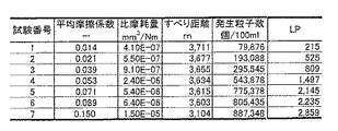
上記すべり摩擦試験を、粘度(即ち、油膜厚さ)の異なる潤滑油(例えば、油供給量4.2L)で繰り返し行うと、図3に示すように、試験番号1〜7における各摩擦係数μ、比摩耗量Ws(mm3/Nm)、すべり距離L(m)、及び発生粒子数Pc(個/100ml)が測定される。これらの測定結果によって潤滑状態評価パラメータLp(Lp=Pc/(k・L)、本発明に係る「第1評価パラメータ」として例示する。)が求められる。そして、図4に示すように、縦軸に摩擦係数μ(本発明に係る「第2評価パラメータ」として例示する。)をとり、横軸に潤滑状態評価パラメータLpをとると第1評価データQ1(検量線)が作成される。また、図5に示すように、縦軸に比摩耗量Ws(本発明に係る「第2評価パラメータ」として例示する。)をとり、横軸に潤滑状態評価パラメータLpをとると第2評価データQ2(検量線)が作成される。これら第1及び第2評価データQ1,Q2は、発生粒子数の複数の粒径範囲毎に応じて複数作成される。 When the above sliding friction test is repeated with lubricating oils having different viscosities (that is, oil film thickness) (for example, oil supply amount 4.2 L), as shown in FIG. The specific wear amount Ws (mm3 / Nm), the sliding distance L (m), and the number of generated particles Pc (pieces / 100 ml) are measured. From these measurement results, a lubrication state evaluation parameter Lp (Lp = Pc / (k · L), exemplified as “first evaluation parameter” according to the present invention) is obtained. As shown in FIG. 4, when the friction coefficient μ (illustrated as “second evaluation parameter” according to the present invention) is taken on the vertical axis and the lubrication state evaluation parameter Lp is taken on the horizontal axis, the first evaluation data Q1. (Calibration curve) is created. In addition, as shown in FIG. 5, the specific wear amount Ws (illustrated as “second evaluation parameter” according to the present invention) is taken on the vertical axis, and the lubrication state evaluation parameter Lp is taken on the horizontal axis. Q2 (calibration curve) is created. A plurality of the first and second evaluation data Q1, Q2 are created according to a plurality of particle size ranges of the number of generated particles.
なお、上記kは、潤滑対象部の摺動面積等に応じて決まる補正係数(例えば、0.1等)である。また、上記すべり摩擦試験1〜4は混合潤滑の初期状態であり、上記すべり摩擦試験5は混合潤滑の中期状態であり、上記すべり摩擦試験6は混合潤滑の後期状態であり、上記すべり摩擦試験7は境界潤滑の状態である。
The k is a correction coefficient (for example, 0.1) determined according to the sliding area of the lubrication target portion. The sliding
(2)粒子数測定器の構成
次に、上記すべり摩擦試験で用いられる粒子数測定器2の構成について説明する。
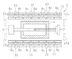
上記粒子数測定器2は、図6に示すように、セル5、1つの半導体レーザ6(本発明に係る「発光体」として例示する。)、1つの遮断光用フォトダイオード7(本発明に係る「遮断光受光体」として例示する。)、多数の第1及び第2散乱光用フォトダイオード8,9(本発明に係る「散乱光受光体」として例示する。)及びコンピュータ(図示せず)を備えている。
(2) Configuration of Particle Number Measuring Device Next, the configuration of the particle
As shown in FIG. 6, the particle
上記セル5は、無色透明のプラスチック製であり、縦寸法0.5mm、横寸法1mmの矩形管状に形成されている。このセル5には、上記すべり摩擦試験で使用される潤滑油が所定の流速で流される。
The
上記半導体レーザ6は、セル5内を流れる潤滑油に所定の波長(例えば、650nm等)のレーザ光を照射する。
The
上記遮断光用フォトダイオード7は、半導体レーザ6からのレーザ光の光軸上でセル5を介して半導体レーザ6と反対側に配設されている。このフォトダイオード7は、潤滑油中の気泡又は微粒子により遮断された遮断光を受光して、所定の遮断光パルス信号に変換する。この遮断光パルス信号のパルス高さは、気泡又は微粒子の粒径に比例した値を示す。
The
多数(図中7個ずつ)の上記第1及び第2散乱光用フォトダイオード8a〜8g,9a〜9gのそれぞれは、半導体レーザ6からのレーザ光の光軸の外周側であって、その光軸に対して平行な直線に沿って隣接して配置されている。各第1及び第2散乱光用フォトダイオード8a〜8g,9a〜9gは、セル5を介して反対側であり且つ回転対象位置に配置されている。各第1及び第2散乱光用フォトダイオード8a〜8g,9a〜9gは、潤滑油中の気泡又は微粒子により散乱された散乱光を受光して、所定の散乱光パルス信号に変換する。また、各第1及び第2散乱光用フォトダイオード8a〜8g,9a〜9gの前面側には、各フォトダイオード8a〜8g,9a〜9gに対向する集光レンズ15a〜15gが配設されている。
Each of a large number (seven in the figure) of the first and second
上記コンピュータは、制御プログラムに従って微粒子の計数に係る各種処理動作を実行するようになっている。即ち、図8に示すように、ステップS1では、上述の各フォトダイオード7,8,9からのパルス信号の入力処理を行う。また、ステップS2では、各パルス信号に基づいて、気泡又は微粒子の粒径と共に散乱パターンP1,P1’,P2、P2’(図7参照)の算出処理を行う。また、ステップS3及びS4では、その算出された散乱パターンP1,P1’,P2,P2’と、予め設定された微粒子の基準散乱パターンSP(図7参照)とを比較して、気泡と微粒子との識別処理を行う。また、ステップS5では、所定の粒径毎の微粒子のカウント処理を行う。
The computer executes various processing operations related to fine particle counting according to a control program. That is, as shown in FIG. 8, in step S1, input processing of pulse signals from the
なお、上記散乱パターンP1,P1’,P2,P2’は、図7に示すように、横軸に、レーザ光の光軸方向に対する各第1及び第2散乱光用フォトダイオード8a〜8g,9a〜9gの配設位置をとり、縦軸に、各第1及び第2散乱光用フォトダイオード8a〜8g,9a〜9gの各散乱光パルス信号の各パルス高さの値をとり、さらに各パルス高さの値を補間してなるグラフである。
As shown in FIG. 7, the scattering patterns P1, P1 ′, P2, and P2 ′ are shown on the horizontal axis in the first and second
ここで、上記ステップS2によって、本発明に係る「粒径算出手段」及び「パターン算出手段」が構成されていると言える。また、上記ステップS3及びS4によって、本発明に係る「識別手段」が構成されていると言える。また、上記ステップS5によって、本発明に係る「計数手段」が構成されていると言える。 Here, it can be said that the “particle diameter calculating means” and the “pattern calculating means” according to the present invention are configured by the step S2. Moreover, it can be said that the "identification means" concerning this invention is comprised by said step S3 and S4. In addition, it can be said that the “counting means” according to the present invention is configured by the step S5.
(3)粒子数測定器の作用
次に、上記粒子数測定器2の作用について説明する。
先ず、セル5内を流れる潤滑油に半導体レーザ6からレーザ光が照射される。このとき、レーザ光の光軸上を潤滑油に含まれる気泡又は微粒子が通過すると、その気泡又は微粒子により遮断された遮断光が遮断光用フォトダイオード7で受光され、その受光と略同期して、その気泡又は微粒子により散乱された散乱光が各第1及び第2散乱光用フォトダイオード8a〜8g,9a〜9gで受光される。
(3) Operation of Particle Number Measuring Device Next, the operation of the particle
First, laser light is irradiated from the
次に、コンピュータに、遮断光用フォトダイオード7から遮断光パルス信号が入力されると共に、各第1及び第2散乱光用フォトダイオード8a〜8g,9a〜9gから各散乱光パルス信号が入力される(図8のステップS1)。次いで、その遮断光パルス信号のパルス高さに基づいて気泡又は微粒子の粒径が算出されると共に、各散乱光パルス信号の各パルス高さに基づいて気泡又は微粒子の散乱パターンP1,P1’,P2,P2’(図7参照)が算出される(ステップS2)。
Next, the cutoff light pulse signal is input from the
ここで、気泡は略球形であるため、各第1及び第2散乱光用フォトダイオード8,9に対する散乱光量は大きくなり、また同じ光量の散乱光を受光することとなる。従って、気泡による散乱パターンP1,P1’(図7参照)は、比較的大きなピークを示し、各第1及び第2散乱光用フォトダイオード8,9の間で略同じパターンを示している。
これに対して、微粒子はセル内を回転しながら通過するため、各第1及び第2散乱光用フォトダイオード8,9に対する散乱光量は極少量となり、また同じ光量の散乱光を受光する確立が低くなる。従って、微粒子による散乱パターンP2,P2’(図7参照)は、比較的小さなピークを示し、各第1及び第2散乱光用フォトダイオード8,9の間で異なるパターンを示している。
Here, since the bubble is substantially spherical, the amount of scattered light with respect to each of the first and second scattered light photodiodes 8 and 9 is increased, and the same amount of scattered light is received. Therefore, the scattering patterns P1 and P1 ′ (see FIG. 7) due to the bubbles show relatively large peaks, and the substantially same pattern is shown between the first and second scattered light photodiodes 8 and 9.
On the other hand, since the fine particles pass through the cell while rotating, the amount of scattered light for each of the first and second scattered light photodiodes 8 and 9 is extremely small, and it has been established that the same amount of scattered light is received. Lower. Therefore, the scattering patterns P2 and P2 ′ (see FIG. 7) due to the fine particles show relatively small peaks, and show different patterns between the first and second scattered light photodiodes 8 and 9.
その後、その算出された散乱パターンP1,P1’,P2,P2’と微粒子の基準散乱パターンSP(図7参照)とがパターン認識されて比較される(ステップS3)。その結果、両パターンが類似しており、微粒子であると識別されると(ステップS4でYES判定)、微粒子数がカウントされることとなる(ステップS5)。一方、両パターンが大きく相違しており、微粒子でない(気泡である)と識別されると(ステップS5でNO判定)、微粒子数はカウントされない。その後、コンピュータは、上記ステップS1〜S5を所定回数(又は所定時間)繰り返し行って、一連の測定処理が終了されることとなる。 Thereafter, the calculated scattering patterns P1, P1 ', P2, P2' and the reference scattering pattern SP (see FIG. 7) of the fine particles are recognized and compared (step S3). As a result, if both patterns are similar and are identified as fine particles (YES in step S4), the number of fine particles is counted (step S5). On the other hand, if the two patterns are greatly different and are identified as not being fine particles (bubbles) (NO in step S5), the number of fine particles is not counted. Thereafter, the computer repeats the above steps S1 to S5 a predetermined number of times (or a predetermined time), and the series of measurement processes is completed.
(3)実施例の効果
本実施例の評価データ作成方法によると、すべり摩擦試験によって、粒子数測定器で潤滑油中の粒子数が測定されて、その測定値から潤滑対象部の単位すべり距離当たりの粒子数を示す潤滑状態評価パラメータLpが算出されると共に、摩擦係数μ及び比摩耗量Wsが測定され、その後、潤滑状態評価パラメータLpと摩擦係数μとの相関関係に基づいて第1評価データQ1が得られると共に、潤滑状態評価パラメータLpと比摩耗量Wsとの相関関係に基づいて第2評価データQ2が得られる。そして、これら第1及び第2評価データQ1,Q2を用いれば、実際の潤滑対象部で測定される粒子数から求められる潤滑状態評価パラメータLpから摩擦係数μ及び比摩耗量Wsを取得できる。その結果、これらの一般的な評価パラメータである摩擦係数μ及び比摩耗量Wsを用いて、大型設備等における潤滑対象部の潤滑状態を正確に評価できる。特に、潤滑油のサンプリング周期を短周期(例えば、数分オーダー等)にすれば、潤滑対象部の潤滑状態をより短時間で評価できる。
(3) Effects of Example According to the evaluation data creation method of this example, the number of particles in the lubricating oil is measured by a particle number measuring device by a sliding friction test, and the unit slip distance of the lubrication target part is determined from the measured value. The lubrication state evaluation parameter Lp indicating the number of particles per unit is calculated, the friction coefficient μ and the specific wear amount Ws are measured, and then the first evaluation is performed based on the correlation between the lubrication state evaluation parameter Lp and the friction coefficient μ. Data Q1 is obtained, and second evaluation data Q2 is obtained based on the correlation between the lubrication state evaluation parameter Lp and the specific wear amount Ws. If the first and second evaluation data Q1 and Q2 are used, the friction coefficient μ and the specific wear amount Ws can be acquired from the lubrication state evaluation parameter Lp obtained from the number of particles measured in the actual lubrication target portion. As a result, it is possible to accurately evaluate the lubrication state of the lubrication target portion in a large facility or the like using the friction coefficient μ and the specific wear amount Ws which are these general evaluation parameters. In particular, if the lubricating oil sampling period is set to a short period (for example, on the order of several minutes), the lubrication state of the lubrication target portion can be evaluated in a shorter time.
また、本実施例では、1つの半導体レーザ6と、1つの遮断光用フォトダイオード7と、多数の第1及び第2散乱光用フォトダイオード8a〜8g,9a〜9gと、コンピュータとを備えて粒子数測定器2を構成したので、コンピュータによって、遮断光用フォトダイオード7の遮断光パルス信号に基づいて気泡又は微粒子の粒径が算出され、多数の第1及び第2散乱光用フォトダイオード8a〜8g,9a〜9gの各散乱光用パルス信号に基づいて散乱パターンP1,P2が算出され、その散乱パターンP1,P2と基準散乱パターンSPとのパターン認識による比較に基づいて気泡と微粒子とが識別され、所定の粒径毎の粒子数のみがカウントされる。このように、微粒子の粒径を光遮断式で測定するようにしたので、潤滑油に含まれる微粒子の比較的大径で広範囲に及ぶ粒径(1μm〜500μm)に対応して微粒子数を計測することができる。さらに、多数の各第1及び第2散乱光用フォトダイオード8a〜8g,9a〜9gから得られる散乱パターンP1,P1’,P2,P2’に基づいて気泡と微粒子とを識別するようにしたので、極めて高精度に両者を識別できる。その結果、この粒子数測定器を用いて上記すべり摩擦試験を行えば、より信頼性の高い第1及び第2評価データQ1,Q2を作成できる。
Further, in this embodiment, one
尚、本発明においては、上記実施例に限られず、目的、用途に応じて本発明の範囲内で種々変更した実施例とすることができる。即ち、上記実施例では、第2評価パラメータとして摩擦係数μ及び比摩耗量Wsを例示したが、これに限定されず、例えば、摩擦係数μ及び/又は比摩耗量Wsに準ずる評価パラメータ(例えば、摩耗率、摩耗速度等)を採用してもよい。 In the present invention, the present invention is not limited to the above embodiment, and various modifications can be made within the scope of the present invention depending on the purpose and application. That is, in the above-described embodiment, the friction coefficient μ and the specific wear amount Ws are exemplified as the second evaluation parameter. However, the present invention is not limited thereto, and for example, an evaluation parameter (for example, the friction coefficient μ and / or specific wear amount Ws) Wear rate, wear rate, etc.) may be employed.
また、上記実施例では、レーザ光の光軸に対して平行な直線上に沿って第1及び第2散乱光用フォトダイオード8a〜8g,9a〜9gを複数配置してなる粒子数測定器2を例示したが、これに限定されず、例えば、図9に示すように、レーザ光の光軸上にあり且つセル5の流れ中心軸上にある点を中心として描かれる円弧上に沿って第1及び第2散乱光用フォトダイオード8a〜8g,9a〜9gを複数配置するようにしてもよい。
Moreover, in the said Example, the particle
また、上記実施例では、散乱パターンP1,P1’,P2P2’と基準散乱パターンSPとがパターン認識により類似している場合に微粒子であることを識別する形態を例示したが、これに限定されず、例えば、図8に示すように、ステップS3にて、散乱パターンP1,P1’,P2,P2’と基準散乱パターンSPとがパターン認識により類似しており、且つ、ステップS’(図中仮想線で示す)にて、第1散乱光用フォトダイオード8a〜8gから得られる第1散乱パターンP1,P2と、第2散乱光用フォトダイオード9a〜9gから得られる第2散乱パターンP1’,P2’と、がパターン認識により類似していない場合に、ステップS4にて微粒子であることを識別するようにしてもよい。なお、上記ステップS3とステップS’との順序を入れ替えてもよい。さらに、ステップS3の替わりにステップS’のみを備える構成としてもよい。
Moreover, in the said Example, although the scattering pattern P1, P1 ', P2P2' and the reference | standard scattering pattern SP illustrated the form identified when it is similar by pattern recognition, it was not limited to this For example, as shown in FIG. 8, in step S3, the scattering patterns P1, P1 ′, P2, P2 ′ and the reference scattering pattern SP are similar by pattern recognition, and step S ′ (virtual in the figure). The first scattering patterns P1 and P2 obtained from the first
潤滑対象部の潤滑状態を評価するための評価データを作成する技術として広く利用される。特に、大型設備の潤滑状態を評価するための評価データを作成する技術として好適に利用される。 It is widely used as a technique for creating evaluation data for evaluating the lubrication state of the lubrication target part. In particular, it is suitably used as a technique for creating evaluation data for evaluating the lubrication state of a large facility.
2;粒子数測定器、5;セル、6;半導体レーザ、7;遮断光用フォトダイオード、8;第1散乱光用フォトダイオード、9;第2散乱光用フォトダイオード、Lp;潤滑状態評価パラメータ、μ;摩擦係数、Ws;比摩耗量、Q1;第1評価データ、Q2;第2評価データ。 2; Particle number measuring device, 5; Cell, 6; Semiconductor laser, 7; Photodiode for blocking light, 8; Photodiode for first scattered light, 9; Photodiode for second scattered light, Lp; , Μ: friction coefficient, Ws: specific wear amount, Q1: first evaluation data, Q2: second evaluation data.
Claims (4)
すべり摩擦試験によって、粒子数測定器で潤滑油中の粒子数を測定して、その測定値から潤滑油中の粒子数の時間変化率を示す第1評価パラメータ(Lp)を算出すると共に、摩耗及び/又は摩擦の状態を示す第2評価パラメータを測定する工程と、
前記第1評価パラメータ(Lp)と前記第2評価パラメータとの相関関係に基づいて評価データを得る工程と、を備え、
「Pc」を前記粒子数測定器で測定される粒子数とし、「k」を前記潤滑対象部の摺動面積に応じて決まる補正係数とし、「L」を前記潤滑対象部の摺動面積及び摺動時間から求まる摺動距離としたとき、前記第1評価パラメータ(Lp)を下記数式により算出することを特徴とする評価データ作成方法。
Lp=Pc/(k・L) A method of creating evaluation data for evaluating the lubrication state of a lubrication target part,
In the sliding friction test, the number of particles in the lubricating oil is measured with a particle number measuring device, and the first evaluation parameter (Lp) indicating the time change rate of the number of particles in the lubricating oil is calculated from the measured value. And / or measuring a second evaluation parameter indicative of the state of friction;
Obtaining evaluation data based on a correlation between the first evaluation parameter (Lp) and the second evaluation parameter ,
“Pc” is the number of particles measured by the particle number measuring device, “k” is a correction coefficient determined according to the sliding area of the lubrication target portion, and “L” is the sliding area of the lubrication target portion and An evaluation data creation method , wherein the first evaluation parameter (Lp) is calculated by the following mathematical formula when the sliding distance is obtained from the sliding time .
Lp = Pc / (k · L)
Priority Applications (1)
| Application Number | Priority Date | Filing Date | Title |
|---|---|---|---|
| JP2006350507A JP4836772B2 (en) | 2006-12-26 | 2006-12-26 | Evaluation data creation method |
Applications Claiming Priority (1)
| Application Number | Priority Date | Filing Date | Title |
|---|---|---|---|
| JP2006350507A JP4836772B2 (en) | 2006-12-26 | 2006-12-26 | Evaluation data creation method |
Publications (2)
| Publication Number | Publication Date |
|---|---|
| JP2008164293A JP2008164293A (en) | 2008-07-17 |
| JP4836772B2 true JP4836772B2 (en) | 2011-12-14 |
Family
ID=39694005
Family Applications (1)
| Application Number | Title | Priority Date | Filing Date |
|---|---|---|---|
| JP2006350507A Active JP4836772B2 (en) | 2006-12-26 | 2006-12-26 | Evaluation data creation method |
Country Status (1)
| Country | Link |
|---|---|
| JP (1) | JP4836772B2 (en) |
Families Citing this family (4)
| Publication number | Priority date | Publication date | Assignee | Title |
|---|---|---|---|---|
| CN102279144A (en) * | 2011-04-06 | 2011-12-14 | 沈怡茹 | Oiliness online detecting device for lubricating oil |
| JP2015031665A (en) * | 2013-08-06 | 2015-02-16 | トライボテックス株式会社 | Particle counter and particle counting method |
| JP6467579B2 (en) * | 2017-04-07 | 2019-02-13 | トライボテックス株式会社 | Particle counting apparatus and particle counting method |
| CN111638151B (en) * | 2020-07-15 | 2022-02-22 | 一汽解放汽车有限公司 | Test method for detecting abrasion resistance of friction pair |
Family Cites Families (8)
| Publication number | Priority date | Publication date | Assignee | Title |
|---|---|---|---|---|
| US5604441A (en) * | 1995-03-14 | 1997-02-18 | Detroit Diesel Corporation | In-situ oil analyzer and methods of using same, particularly for continuous on-board analysis of diesel engine lubrication systems |
| JPH1019788A (en) * | 1996-07-03 | 1998-01-23 | Nippon Soken Inc | Measurement system for soot in lubricating oil |
| JP3659891B2 (en) * | 2001-01-12 | 2005-06-15 | トライボ・テックス株式会社 | Lubrication target part diagnosis system and lubrication target part diagnosis method |
| US7172903B2 (en) * | 2002-03-12 | 2007-02-06 | Exxonmobil Research And Engineering Company | Method for on-line monitoring of lubricating oil using light in the visible and near IR spectra |
| JP3694277B2 (en) * | 2002-05-28 | 2005-09-14 | トライボ・テックス株式会社 | Lubrication target part diagnosis method and lubrication target part diagnosis system |
| JP3626744B2 (en) * | 2002-06-18 | 2005-03-09 | 東京電力株式会社 | Wear particle trapping device, lubrication target part diagnosis method, and lubrication target part diagnosis system |
| JP3910118B2 (en) * | 2002-08-05 | 2007-04-25 | 株式会社プラントテクノス | Liquid particle image analyzer |
| JP4719587B2 (en) * | 2006-02-21 | 2011-07-06 | トライボテックス株式会社 | Fine particle counter, fine particle counting method using the same, and lubrication target part diagnosis system including the same |
-
2006
- 2006-12-26 JP JP2006350507A patent/JP4836772B2/en active Active
Also Published As
| Publication number | Publication date |
|---|---|
| JP2008164293A (en) | 2008-07-17 |
Similar Documents
| Publication | Publication Date | Title |
|---|---|---|
| JP4965561B2 (en) | Cytometer cell counting and sizing system | |
| Sun et al. | Online oil debris monitoring of rotating machinery: A detailed review of more than three decades | |
| US7788969B2 (en) | Combination contaminant size and nature sensing system and method for diagnosing contamination issues in fluids | |
| JP4719587B2 (en) | Fine particle counter, fine particle counting method using the same, and lubrication target part diagnosis system including the same | |
| US8675195B2 (en) | Device for determining particle sizes | |
| JP4836772B2 (en) | Evaluation data creation method | |
| CN107076547B (en) | Method and system for examining the chip for being used for electricity, optics or photoelectricity | |
| CN113015897A (en) | Slurry monitoring and single particle detection in combination with bulk size distribution | |
| KR20180000015A (en) | High accuracy real-time particle counter | |
| EP2221599B1 (en) | System and Method for Distinguishing Particles in a Transient Fluid | |
| CN106716112B (en) | For examining the method and system for being used for the transparent wafers of electricity, optics or photoelectricity | |
| JP5079562B2 (en) | Contour shape measurement method | |
| WO2014074413A1 (en) | Film thickness, refractive index, and extinction coefficient determination for film curve creation and defect sizing in real time | |
| JP4716055B2 (en) | Laser diffraction / scattering particle size distribution analyzer | |
| Gu et al. | A model for aerosol mass concentration using an optical particle counter | |
| JP2008164294A (en) | Lubrication state evaluating device, lubrication state evaluating method, program and recording medium | |
| Krogsøe et al. | Performance of a light extinction based wear particle counter under various contamination levels | |
| JP6191477B2 (en) | Particle size measuring apparatus and particle size measuring method | |
| Pilný et al. | Reproducibility of a reaming test | |
| JP4079374B2 (en) | Method for evaluating the number concentration of suspended particles with a specific particle size | |
| JP7397468B2 (en) | Air bubble measuring device and method | |
| Wang et al. | On-line oil monitoring sensors fusion for aircraft health management | |
| JP3123009U (en) | Laser diffraction / scattering particle size distribution analyzer | |
| KR0150054B1 (en) | On-line monitoring method and device of wear particles in lubricant | |
| BOUTS | Characterization of lateral migration dynamics of particles experiencing the Segré-Silberberg effect |
Legal Events
| Date | Code | Title | Description |
|---|---|---|---|
| A621 | Written request for application examination |
Free format text: JAPANESE INTERMEDIATE CODE: A621 Effective date: 20091218 |
|
| A521 | Request for written amendment filed |
Free format text: JAPANESE INTERMEDIATE CODE: A523 Effective date: 20101209 |
|
| A131 | Notification of reasons for refusal |
Free format text: JAPANESE INTERMEDIATE CODE: A131 Effective date: 20110614 |
|
| A521 | Request for written amendment filed |
Free format text: JAPANESE INTERMEDIATE CODE: A523 Effective date: 20110802 |
|
| TRDD | Decision of grant or rejection written | ||
| A01 | Written decision to grant a patent or to grant a registration (utility model) |
Free format text: JAPANESE INTERMEDIATE CODE: A01 Effective date: 20110906 |
|
| A01 | Written decision to grant a patent or to grant a registration (utility model) |
Free format text: JAPANESE INTERMEDIATE CODE: A01 |
|
| A61 | First payment of annual fees (during grant procedure) |
Free format text: JAPANESE INTERMEDIATE CODE: A61 Effective date: 20110927 |
|
| FPAY | Renewal fee payment (event date is renewal date of database) |
Free format text: PAYMENT UNTIL: 20141007 Year of fee payment: 3 |
|
| R150 | Certificate of patent or registration of utility model |
Ref document number: 4836772 Country of ref document: JP Free format text: JAPANESE INTERMEDIATE CODE: R150 Free format text: JAPANESE INTERMEDIATE CODE: R150 |
|
| R250 | Receipt of annual fees |
Free format text: JAPANESE INTERMEDIATE CODE: R250 |
|
| R250 | Receipt of annual fees |
Free format text: JAPANESE INTERMEDIATE CODE: R250 |
|
| R250 | Receipt of annual fees |
Free format text: JAPANESE INTERMEDIATE CODE: R250 |
|
| R250 | Receipt of annual fees |
Free format text: JAPANESE INTERMEDIATE CODE: R250 |
|
| R250 | Receipt of annual fees |
Free format text: JAPANESE INTERMEDIATE CODE: R250 |
|
| R250 | Receipt of annual fees |
Free format text: JAPANESE INTERMEDIATE CODE: R250 |
|
| R250 | Receipt of annual fees |
Free format text: JAPANESE INTERMEDIATE CODE: R250 |
|
| R250 | Receipt of annual fees |
Free format text: JAPANESE INTERMEDIATE CODE: R250 |
|
| R250 | Receipt of annual fees |
Free format text: JAPANESE INTERMEDIATE CODE: R250 |
|
| R250 | Receipt of annual fees |
Free format text: JAPANESE INTERMEDIATE CODE: R250 |