JP4835984B2 - Display device - Google Patents
Display device Download PDFInfo
- Publication number
- JP4835984B2 JP4835984B2 JP2006151767A JP2006151767A JP4835984B2 JP 4835984 B2 JP4835984 B2 JP 4835984B2 JP 2006151767 A JP2006151767 A JP 2006151767A JP 2006151767 A JP2006151767 A JP 2006151767A JP 4835984 B2 JP4835984 B2 JP 4835984B2
- Authority
- JP
- Japan
- Prior art keywords
- display
- display device
- color
- electroluminescent
- substrate
- Prior art date
- Legal status (The legal status is an assumption and is not a legal conclusion. Google has not performed a legal analysis and makes no representation as to the accuracy of the status listed.)
- Expired - Fee Related
Links
- 239000000758 substrate Substances 0.000 claims description 37
- 229910052751 metal Inorganic materials 0.000 claims description 22
- 239000002184 metal Substances 0.000 claims description 22
- 238000005401 electroluminescence Methods 0.000 claims description 5
- 239000010410 layer Substances 0.000 description 24
- XAGFODPZIPBFFR-UHFFFAOYSA-N aluminium Chemical compound [Al] XAGFODPZIPBFFR-UHFFFAOYSA-N 0.000 description 9
- 229910052782 aluminium Inorganic materials 0.000 description 8
- 239000012044 organic layer Substances 0.000 description 6
- 239000011521 glass Substances 0.000 description 5
- 239000000463 material Substances 0.000 description 4
- 229920003002 synthetic resin Polymers 0.000 description 4
- 239000000057 synthetic resin Substances 0.000 description 4
- 229920000178 Acrylic resin Polymers 0.000 description 3
- 239000004925 Acrylic resin Substances 0.000 description 3
- 230000005540 biological transmission Effects 0.000 description 3
- 239000000976 ink Substances 0.000 description 3
- 229920005668 polycarbonate resin Polymers 0.000 description 3
- 239000004431 polycarbonate resin Substances 0.000 description 3
- 239000011888 foil Substances 0.000 description 2
- 238000005286 illumination Methods 0.000 description 2
- 230000002093 peripheral effect Effects 0.000 description 2
- 239000005394 sealing glass Substances 0.000 description 2
- 239000000853 adhesive Substances 0.000 description 1
- 230000001070 adhesive effect Effects 0.000 description 1
- 230000005525 hole transport Effects 0.000 description 1
- 238000002347 injection Methods 0.000 description 1
- 239000007924 injection Substances 0.000 description 1
- 230000010287 polarization Effects 0.000 description 1
- 238000012805 post-processing Methods 0.000 description 1
Images


Description
本発明は、表示装置に関するものであり、特に電界発光表示素子を備えた表示装置に関する。 The present invention relates to a display device, and more particularly, to a display device including an electroluminescent display element.
電界発光表示素子を備えた表示装置としては、例えば下記特許文献1および特許文献2がある。この特許文献1に記載の表示装置は、特許文献1の例えば図1に示されている様に、電界発光表示素子20を構成する金属電極29(背面電極)をガラス基板25のほぼ全面に設けることによって、太陽光などの外光が射した場合でも電界発光表示素子20の略全範囲がほぼ一様な色調(金属電極29の色調であるアルミニウム色)に見え、見栄えが悪くなる虞がないというものである。
As a display device including an electroluminescent display element, for example, there are
また、特許文献2に記載の表示素子は、特許文献2の例えば図2に示されている様に、有機EL素子40(電界発光表示素子)の基板6面に直線偏光板11および複屈折板23からなる円偏光手段49を貼り合わせることによって、外部から入射して有機EL素子40の金属電極1で反射した反射光が入射側に出射するのを抑えて、有機EL素子40の表示画像とのコントラスト比を向上させるというものである。
しかしながら、上記特許文献1に記載の表示装置は、電界発光表示素子20のみは略全範囲がほぼ一様な色調に見えるものの、その図1に示されている様に、電界発光表示素子20の前方側に窓部21を有する文字板12(表示板)が配置されているため、窓部21の端面(切口)が見えると共に、文字板12の表面側に設けられている遮光層12bの色調(黒色)と電界発光表示素子20の色調(アルミニウム色)とが異なり、違和感がある。また、図7に示されている文字板39は穴(窓部)を設けない代わりに、その箇所を透過部40としたものである。従って、穴を設けることによって生じる端面(切口)は見えなくなるが、透過部40を透して視認される電界発光表示素子20と、文字板39の表面側に設けられている遮光層39bとの色調が異なる。
However, in the display device described in
また、特許文献2に於いては、有機EL素子40単体状態での視認性は改善するが、この様な有機EL素子を例えば特許文献1の図7に示されている表示装置に用いた場合、円偏光手段49によって反射光が抑えられるため、金属電極の色調であるアルミニウム色が失せてしまう。更に、有機EL素子からの表示光が円偏光手段を透過することによって表示輝度が低下する虞がある。
Further, in
本発明はこの様な点に鑑みなされたもので、電界発光表示素子の前面側に表示板を配置した表示装置において、電界発光表示素子と表示板とが一体感を有するとともに、金属感を有する表示装置を提供することを目的とする。 The present invention has been made in view of the above points, and in a display device in which a display plate is arranged on the front side of an electroluminescent display element, the electroluminescent display element and the display plate have a sense of unity and a metallic feeling. An object is to provide a display device.
本発明は前記目的を達成するため、金属からなる背面電極を有する電界発光表示素子と、前記電界発光表示素子の前面側に配置された表示板と、を備えた表示装置であって、前記表示板は、光透過性で暗色系の基板と、表示部と、前記電界発光表示素子の表示領域および前記表示部を除いて設けられた地部と、を有し、
前記地部は、前記背面電極の色調と同色もしくは近似色の金属調であるものである。
Since the present invention to achieve the object, a display device including a light emitting display device having a back electrode made of a metal, and a display panel arranged on the front side of the electroluminescent display elements, the display The plate has a light-transmissive and dark-colored substrate, a display unit, and a ground region provided excluding the display region of the electroluminescent display element and the display unit ,
The ground portion has a metal tone having the same color as that of the back electrode or an approximate color .
また、金属からなる背面電極を有する電界発光表示素子と、前記電界発光表示素子の前面側に配置された表示板と、を備えた表示装置であって、前記表示板は、無色透明の基板と、前記基板の表面側または裏面側に設けた光透過性で暗色系の半透明層と、表示部と、前記電界発光表示素子の表示領域および前記表示部を除いて設けられた地部と、を有し、前記地部は、前記背面電極の色調と同色もしくは近似色の金属調であるものである。 Further, a display device including a light emitting display device having a back electrode made of a metal, and a display panel arranged on the front side of the electroluminescent display elements, the display panel includes a substrate of clear colorless , a translucent layer of dark color of a light transmissive provided on the surface side or back side of the substrate, a display unit, and a land portion provided with the exception of the display area and the display unit of the EL display device, The ground portion has a metal tone having the same color as or a color similar to the color tone of the back electrode .
また、金属からなる背面電極を有する電界発光表示素子と、前記電界発光表示素子の前面側に配置された表示板と、を備えた表示装置であって、前記表示板は、無色透明の基板と、表示部と、前記電界発光表示素子の表示領域および前記表示部を除いて設けられた地部と、を有し、前記地部は、前記背面電極の色調と同色もしくは近似色の金属調であるものである。 Further, a display device including a light emitting display device having a back electrode made of a metal, and a display panel arranged on the front side of the electroluminescent display elements, the display panel includes a substrate of clear colorless A display portion, and a ground portion provided excluding the display area of the electroluminescent display element and the display portion, and the ground portion has a metal tone of the same color as or an approximate color of the color of the back electrode. There is something.
また、前記表示板は、表面側にヘアラインが設けられているものである。 Moreover, the said display board is provided with the hairline in the surface side.
また、前記地部が前記表示板の裏面側に設けられているものである。 The ground portion is provided on the back side of the display board.
電界発光表示素子の前面側に表示板を配置した表示装置において、電界発光表示素子と表示板とが一体感を有するとともに、金属感を有する表示装置を得ることができる。 In the display device in which the display plate is arranged on the front side of the electroluminescent display element, the electroluminescent display element and the display plate have a sense of unity and a display device having a metallic feeling can be obtained.
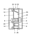
本発明を各実施形態に基づいて説明する。図1〜図4に本発明の第1実施形態を示す。図1は電界発光表示素子1を備えた表示装置の正面図であり、図2はその断面図(図1に於けるA−A断面)である。図3は電界発光表示素子1の詳細を示す断面図(図1に於けるB−B断面相当)である。図4は表示板の部分断面図である。
The present invention will be described based on each embodiment. 1 to 4 show a first embodiment of the present invention. FIG. 1 is a front view of a display device provided with an
本実施形態に於ける表示装置は、速度計1と回転計2を有している。なお、回転計2の説明は省略する。速度計1は、電界発光表示素子3と、電界発光表示素子3の前面側に設けられ車両の速度を現す目盛,数字,文字などの表示部4が施された表示板5と、表示部4を指し示す指針6と、指針6を回動させる表示器本体7と、表示器本体7および電界発光表示素子3と電気的に接続され、表示器本体7や電界発光表示素子3を駆動する駆動回路などが搭載された硬質の回路基板8と、指針6および表示板5を照明する光源としての発光ダイオード9,9Aを備えている。
The display device in the present embodiment includes a
また、表示板5と回路基板8との間に配置されたケース部材10と、回路基板8の裏面側を覆うカバー11と、表示板5の周縁前方側に配置され表示板5の可視領域を定める開口部12を有する例えば黒色の合成樹脂からなる見返し部材13と、表示板5の前方側を被う無色透明な合成樹脂からなる透視板14を備えている。
Further, a
電界発光表示素子3は、例えば日字形の表示セグメントを有しており、有機層を発光させることにより表示セグメントが表示部(図示せず)として表示されるものである。表示装置が例えば車両に備えられた場合は、車両の走行距離や外気温などが表示される。図3に電界発光表示素子3の断面を示す。電界発光表示素子3は、透光性基板であるガラス基板15の後面に、ITOからなる透明電極16と、絶縁層17と、有機層18と、アルミニウム等からなる背面電極19とを順次積層したものであり、背面電極19の後方には封止ガラス20が配設されている。封止ガラス20は接着剤21によってガラス基板15に固着されている。そして、透明電極16と背面電極19に電圧を印加することにより有機層18が発光する様になっている。
The
なお、有機層18は少なくとも発光層があれば良いが、正孔注入層,正孔輸送層,電子輸送層があっても良い。また、背面電極19は少なくとも表示セグメントに対応する箇所に形成されていれば良いが、ガラス基板15,透明電極16,絶縁層17及び有機層18が略透明であるのに対し、背面電極19はアルミニウム等の金属からなるものであり、ほぼ鏡面となって見えるため、背面電極19をガラス基板15の一部ではなく、略全範囲に形成し電界発光表示素子3の全面が略一様に見えるようにしてある。
The
指針6は、例えば無色透明な合成樹脂からなる指示部22を有しており、指示部22の裏面には白色の箔(図示せず)がホットスタンプされている。そして、例えば赤色で発光する指針照明用の発光ダイオード9が点灯した際は、赤色の光が白色の箔に反射して指示部22が赤色で視認されるようになっている。
The
ケース部材10は遮光性のある白色の合成樹脂からなり、外周壁23と、表示板5が載置される載置部24と、指針照明用の発光ダイオード9を囲む筒部25と、ホルダー26などを有している。なお、電界発光表示素子3はホルダー26に保持されている。
The
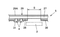
表示板5は、光透過性で暗色系の材料(例えば黒色半透明)からなるアクリル樹脂やポリカーボネート樹脂からなる基板27の裏面側に、表示部4と、電界発光表示素子3の背面電極19の色調と同色もしくは近似色である金属調の地部28とを有し、基板27の表面側には微細なヘアライン29が設けてある。本実施形態に於けるヘアライン29は、例えば基板27の中心(指針6の中心に対応)から放射状に、或いは基板27の中心を原点とする径の異なる同心円を複数形成したものであって、けがき加工やプレス加工などによって基板27の表面に直に設けてある。なお、基板27は黒色に限定するものではなく、光透過性を有していれば濃灰,濃茶,濃青などの暗色系であれば良い。
The
また、地部28は表示部4および電界発光表示素子3の表示領域S(図1に於いて破線で囲んだ範囲)となる箇所を除いて設けられたものであり、背面電極19がアルミニウムからなる場合は、アルミニウムと同色もしくは近似色であるインク(例えばアルミニウム粉が混入されたインク)を印刷する。この際、表示領域Sが背面電極19の範囲よりも狭くなる(平面視した際、背面電極19の周縁と重なる)様に地部28を印刷する。また、地部28の裏面側(発光ダイオード側)には例えば黒色の遮光層30が設けてある。この遮光層30は、表示板照明用の発光ダイオード9Aが点灯した際に地部28が透けた場合、それを防ぐためであるが、必要に応じて設ければ良い。また、表示部4に対応した箇所には例えば白色の透過性表示層31が設けてある。なお、図1に於いては、表示部4を黒色で、地部28を無色で示す。
The
この様に構成された表示装置に於いて、昼間時であって電界発光表示素子3の非表示時には、外光が表示板5の表示領域Sを透過して電界発光表示素子3の背面電極19であるアルミニウムに反射するが、文字板5の基板27が黒色の半透明材であるために、表示領域S内が黒みを帯びた金属調で視認される。そして、電界発光表示素子3に電圧が印加されると有機層18が発光し、黒みを帯びた金属調の表示領域S内に表示部(図示せず)が表示される。また、表示領域S以外は外光が基板27を透過して裏面側に設けてある地部28および透過性表示層31に反射して、表示部4が黒みを帯びた白色で、表示部4以外が黒みを帯びた金属調でそれぞれ視認される。なお、表示板5の全面はヘアライン模様が視認される。また、表示部4は昼間時であっても例えば白色で発光する表示板照明用の発光ダイオード9Aを点灯させて白色で透過表示させるようにしても良い。
In the display device configured as described above, when the
この様に、表示板5の地部28の色調を電界発光表示素子3の背面電極19の色調と同色もしくは近似色である金属調としたことにより、表示板5の表示部4あるいは電界発光表示素子3の表示部(図示せず)の表示時,非表示時に関わらず、電界発光表示素子3と表示板5との段差感や色調の違いなどを目立たなくして、一体感を有すると共に金属感のある表示装置を得ることができる。なお、見返し部材13を金属調色とすれば、表示装置全体に金属感を持たせることができる。
In this way, the color tone of the
また、表示板5の基板27を黒色半透明の材料としたことにより、黒みを帯びた金属調の地部28および電界発光表示素子3内に、表示部4および電界発光表示素子3の表示部(図示せず)が明るく表示されるため、コントラストも良い。また、前述した特許文献2に記載されている様な円偏光手段を用いないため、背面電極19で反射した光が抑えられてアルミニウム色が失せてしまうことが無いと共に、コストダウンとなり、円偏光手段を透過することによる表示輝度の低下も抑えられる。
Further, since the
また、ヘアライン29を表示板5の表面側(基板27の表面)に設けたことにより、金属質感を向上させることができる。更に、黒色半透明材の基板27上にヘアライン29を設けることにより、金属質感に加え、高級感を与えることができる。また、地部28および透過性表示層31を基板27の裏面側に設けることにより、表示板5の表面側に印刷による段差が現れず見栄えが良い。
Further, by providing the
なお、夜間など周囲が暗い時は、表示板5の表示領域S(電界発光表示素子3)および地部28に金属感は得られないが、ほぼ同一色調で視認され、表示板5と電界発光表示素子3との一体感は得られる。夜間時に於いても金属感を得たい場合には、表示板5の前面側から光を照射するように構成すれば良い。
When the surroundings are dark, such as at night, the display area S (electroluminescence display element 3) and the
図5は本発明の第2実施形態を示す表示板の部分断面図である。前記第1実施形態と同一もしくは相当箇所には同一符号を付し、その詳細説明は省略する。なお、表示板以外は前記第1実施形態と同じであるため、省略する。 FIG. 5 is a partial cross-sectional view of a display panel showing a second embodiment of the present invention. The same or corresponding portions as those in the first embodiment are denoted by the same reference numerals, and detailed description thereof is omitted. In addition, since it is the same as that of the said 1st Embodiment except a display board, it abbreviate | omits.
本実施形態に於ける表示板5は、無色透明な例えばアクリル樹脂やポリカーボネート樹脂からなる基板27の表面側に光透過性である例えば黒色の半透明層32を全面に設けることによって、本発明における光透過性で暗色系の基板としたものである。そして、この半透明層32上に例えば無色透明なヘアライン29を設け、基板27の裏面側には前記第1実施形態と同様に表示部4および電界発光表示素子3の表示領域Sとなる箇所を除いて電界発光表示素子3の背面電極19の色調と同色もしくは近似色である金属調の地部28と黒色の遮光層30および白色の透過性表示層31を設けたものである。
The
ヘアライン29は、例えば無色透明なインクを前記第1実施形態と同様に放射状あるいは同心円状に複数印刷したものである。なお、ヘアライン29は印刷に限定するものではない。また、半透明層32も光透過性を有していれば黒色に限らず濃灰,濃茶,濃青などの暗色系であれば良い。また、半透明層32は基板27の裏面側(基板27と地部28との間)全面に設けても良い。
The
本実施形態に於いても、前記第1実施形態と同様に視認され、一体感を有すると共に金属感のある表示装置が得られる。 Also in the present embodiment, a display device that is visually recognized in the same manner as in the first embodiment and has a sense of unity and a metallic feeling can be obtained.
図6は本発明の第3実施形態を示す表示板の部分断面図である。表示板以外は前記各実施形態と同じであるため、同一もしくは相当箇所には同一符号を付し、詳細および表示板以外の説明は省略する。 FIG. 6 is a partial cross-sectional view of a display panel showing a third embodiment of the present invention. Since the components other than the display panel are the same as those of the above-described embodiments, the same or corresponding parts are denoted by the same reference numerals, and details and descriptions other than the display panel are omitted.
本実施形態に於ける表示板5は、前記第1実施形態で述べた様な暗色系の材料からなる基板27でもなければ、前記第2実施形態で述べた様に基板27に暗色系の半透明層32を設けたものでもなく、無色透明な例えばアクリル樹脂やポリカーボネート樹脂からなる基板27である。そして、基板27表面側であって観者側に前記各実施形態と同様な放射状あるいは同心円状のヘアライン29を有する透明なヘアライン層29Aを転写などによって設け、裏面側に前記各実施形態と同様に表示部4および電界発光表示素子3の表示領域Sとなる箇所を除いて電界発光表示素子3の背面電極19の色調と同色もしくは近似色である金属調の地部28と黒色の遮光層30および白色の透過性表示層31を設けたものである。
The
この様に構成したことにより、表示板5の表示部4あるいは電界発光表示素子3の表示部の表示時,非表示時に関わらず、電界発光表示素子3と表示板5との段差感や色調の違いなどを目立たなくして、一体感を有すると共に金属感のある表示装置を得ることができる。また、ヘアライン29を表示板5の表面側(観者側)に設けたことにより、金属質感を更に向上させることができる。
With this configuration, the difference in level and color tone between the
3 電界発光表示素子
4 表示部
5 表示板
19 背面電極
27 基板
28 地部
29 ヘアライン
DESCRIPTION OF
Claims (5)
前記表示板は、光透過性で暗色系の基板と、表示部と、前記電界発光表示素子の表示領域および前記表示部を除いて設けられた地部と、を有し、
前記地部は、前記背面電極の色調と同色もしくは近似色の金属調であることを特徴とする表示装置。 A display device comprising a light emitting display device having a back electrode made of a metal, and a display panel arranged on the front side of the electroluminescent display element,
The display board includes a light-transmissive and dark-colored substrate, a display unit, and a ground portion provided excluding the display region of the electroluminescent display element and the display unit ,
The display device according to claim 1, wherein the ground portion has a metal tone of the same color or an approximate color as a color tone of the back electrode .
前記表示板は、無色透明の基板と、前記基板の表面側または裏面側に設けた光透過性で暗色系の半透明層と、表示部と、前記電界発光表示素子の表示領域および前記表示部を除いて設けられた地部と、を有し、
前記地部は、前記背面電極の色調と同色もしくは近似色の金属調であることを特徴とする表示装置。 A display device comprising a light emitting display device having a back electrode made of a metal, and a display panel arranged on the front side of the electroluminescent display element,
The display panel includes a substrate of a colorless transparent, translucent layer of dark color of a light transmissive provided on the surface side or back side of the substrate, the display unit and the display area of the electro-luminescence display device and the display unit And a ground portion provided except for ,
The display device according to claim 1, wherein the ground portion has a metal tone of the same color or an approximate color as a color tone of the back electrode .
前記表示板は、無色透明の基板と、表示部と、前記電界発光表示素子の表示領域および前記表示部を除いて設けられた地部と、を有し、
前記地部は、前記背面電極の色調と同色もしくは近似色の金属調であることを特徴とする表示装置。 A display device comprising a light emitting display device having a back electrode made of a metal, and a display panel arranged on the front side of the electroluminescent display element,
The display plate includes a colorless and transparent substrate, a display unit, and a ground portion provided excluding the display region of the electroluminescent display element and the display unit ,
The display device according to claim 1, wherein the ground portion has a metal tone of the same color or an approximate color as a color tone of the back electrode .
Priority Applications (1)
| Application Number | Priority Date | Filing Date | Title |
|---|---|---|---|
| JP2006151767A JP4835984B2 (en) | 2006-05-31 | 2006-05-31 | Display device |
Applications Claiming Priority (1)
| Application Number | Priority Date | Filing Date | Title |
|---|---|---|---|
| JP2006151767A JP4835984B2 (en) | 2006-05-31 | 2006-05-31 | Display device |
Publications (3)
| Publication Number | Publication Date |
|---|---|
| JP2007322650A JP2007322650A (en) | 2007-12-13 |
| JP2007322650A5 JP2007322650A5 (en) | 2008-07-31 |
| JP4835984B2 true JP4835984B2 (en) | 2011-12-14 |
Family
ID=38855525
Family Applications (1)
| Application Number | Title | Priority Date | Filing Date |
|---|---|---|---|
| JP2006151767A Expired - Fee Related JP4835984B2 (en) | 2006-05-31 | 2006-05-31 | Display device |
Country Status (1)
| Country | Link |
|---|---|
| JP (1) | JP4835984B2 (en) |
Families Citing this family (9)
| Publication number | Priority date | Publication date | Assignee | Title |
|---|---|---|---|---|
| JP5188874B2 (en) * | 2008-05-09 | 2013-04-24 | 矢崎総業株式会社 | Display device |
| JP6068862B2 (en) * | 2012-08-02 | 2017-01-25 | 矢崎総業株式会社 | Indicator dial |
| JP2015099084A (en) * | 2013-11-19 | 2015-05-28 | カルソニックカンセイ株式会社 | Dial structure |
| JP5673790B2 (en) * | 2013-12-09 | 2015-02-18 | 株式会社デンソー | Organic EL display device |
| KR102608417B1 (en) | 2016-08-19 | 2023-12-01 | 삼성디스플레이 주식회사 | Organic light emitting display device and method for manufacturing the same |
| EP3395290A1 (en) | 2017-04-26 | 2018-10-31 | Ivoclar Vivadent AG | Dental light curing apparatus |
| JP6854197B2 (en) * | 2017-06-09 | 2021-04-07 | 矢崎総業株式会社 | Vehicle display device and design board |
| JP6969325B2 (en) * | 2017-11-29 | 2021-11-24 | 日本精機株式会社 | Display device |
| JP2019100752A (en) * | 2017-11-29 | 2019-06-24 | 日本精機株式会社 | Display unit |
Family Cites Families (4)
| Publication number | Priority date | Publication date | Assignee | Title |
|---|---|---|---|---|
| JP3275283B2 (en) * | 1995-04-28 | 2002-04-15 | 日本精機株式会社 | Transmission illumination type display panel |
| JP3692925B2 (en) * | 2000-10-26 | 2005-09-07 | 日本精機株式会社 | Display device |
| JP2004109450A (en) * | 2002-09-18 | 2004-04-08 | Seiko Epson Corp | Display apparatus, video display device, and electronic equipment |
| JP2006113045A (en) * | 2004-09-14 | 2006-04-27 | Denso Corp | Dial plate for measuring instrument and measuring instrument using it |
-
2006
- 2006-05-31 JP JP2006151767A patent/JP4835984B2/en not_active Expired - Fee Related
Also Published As
| Publication number | Publication date |
|---|---|
| JP2007322650A (en) | 2007-12-13 |
Similar Documents
| Publication | Publication Date | Title |
|---|---|---|
| JP4251292B2 (en) | Display device | |
| JP4835984B2 (en) | Display device | |
| JP2008089479A (en) | Dial plate for indicating instrument | |
| JP2011123406A (en) | Liquid crystal display apparatus for vehicle | |
| JP6729623B2 (en) | Vehicle display device | |
| WO2014168067A1 (en) | Display device | |
| JP4930045B2 (en) | Display device | |
| JP4619247B2 (en) | Display board | |
| JP2009180623A (en) | Indicating instrument | |
| JP4462138B2 (en) | Instrument display board and pointer instrument having the same | |
| JP2008002996A (en) | Indicator meter | |
| JP4797503B2 (en) | Display device | |
| JP2007206222A (en) | Display device | |
| JP2006208081A (en) | Indicating instrument | |
| JP4905754B2 (en) | Display device | |
| JP4923676B2 (en) | Display device | |
| JP5509613B2 (en) | Display device | |
| JP4632021B2 (en) | Instrument device | |
| JP2000213966A (en) | Display device | |
| JP2003202247A (en) | Pointer type measuring instrument | |
| JP2006234699A (en) | Display device | |
| JP2008002963A (en) | Display board for instrument and instrument equipped with the same | |
| JP2018097233A (en) | Liquid crystal display device | |
| JP4737494B2 (en) | Instrument device | |
| US10539299B2 (en) | Display device |
Legal Events
| Date | Code | Title | Description |
|---|---|---|---|
| A521 | Request for written amendment filed |
Free format text: JAPANESE INTERMEDIATE CODE: A523 Effective date: 20080613 |
|
| A621 | Written request for application examination |
Free format text: JAPANESE INTERMEDIATE CODE: A621 Effective date: 20080613 |
|
| A977 | Report on retrieval |
Free format text: JAPANESE INTERMEDIATE CODE: A971007 Effective date: 20110427 |
|
| A131 | Notification of reasons for refusal |
Free format text: JAPANESE INTERMEDIATE CODE: A131 Effective date: 20110602 |
|
| A521 | Request for written amendment filed |
Free format text: JAPANESE INTERMEDIATE CODE: A523 Effective date: 20110627 |
|
| TRDD | Decision of grant or rejection written | ||
| A01 | Written decision to grant a patent or to grant a registration (utility model) |
Free format text: JAPANESE INTERMEDIATE CODE: A01 Effective date: 20110902 |
|
| A01 | Written decision to grant a patent or to grant a registration (utility model) |
Free format text: JAPANESE INTERMEDIATE CODE: A01 |
|
| A61 | First payment of annual fees (during grant procedure) |
Free format text: JAPANESE INTERMEDIATE CODE: A61 Effective date: 20110915 |
|
| FPAY | Renewal fee payment (event date is renewal date of database) |
Free format text: PAYMENT UNTIL: 20141007 Year of fee payment: 3 |
|
| R150 | Certificate of patent or registration of utility model |
Free format text: JAPANESE INTERMEDIATE CODE: R150 |
|
| LAPS | Cancellation because of no payment of annual fees |