JP4834439B2 - Stage apparatus and control method thereof, exposure apparatus and device manufacturing method - Google Patents
Stage apparatus and control method thereof, exposure apparatus and device manufacturing method Download PDFInfo
- Publication number
- JP4834439B2 JP4834439B2 JP2006095850A JP2006095850A JP4834439B2 JP 4834439 B2 JP4834439 B2 JP 4834439B2 JP 2006095850 A JP2006095850 A JP 2006095850A JP 2006095850 A JP2006095850 A JP 2006095850A JP 4834439 B2 JP4834439 B2 JP 4834439B2
- Authority
- JP
- Japan
- Prior art keywords
- stage
- movement
- surface plate
- mass
- reaction force
- Prior art date
- Legal status (The legal status is an assumption and is not a legal conclusion. Google has not performed a legal analysis and makes no representation as to the accuracy of the status listed.)
- Expired - Fee Related
Links
- 238000000034 method Methods 0.000 title claims description 20
- 238000004519 manufacturing process Methods 0.000 title claims description 15
- 238000006243 chemical reaction Methods 0.000 claims description 163
- 230000005484 gravity Effects 0.000 claims description 32
- 230000001133 acceleration Effects 0.000 claims description 12
- 230000008569 process Effects 0.000 claims description 11
- 239000000758 substrate Substances 0.000 claims description 10
- 230000007246 mechanism Effects 0.000 claims description 9
- 230000003287 optical effect Effects 0.000 claims description 7
- 230000004044 response Effects 0.000 claims description 5
- 239000004065 semiconductor Substances 0.000 description 12
- 238000009434 installation Methods 0.000 description 5
- 230000005540 biological transmission Effects 0.000 description 4
- 230000002411 adverse Effects 0.000 description 3
- 238000010586 diagram Methods 0.000 description 3
- 230000000694 effects Effects 0.000 description 3
- 230000014509 gene expression Effects 0.000 description 3
- 238000002955 isolation Methods 0.000 description 3
- 230000002093 peripheral effect Effects 0.000 description 3
- 238000005530 etching Methods 0.000 description 2
- 230000020169 heat generation Effects 0.000 description 2
- 238000007689 inspection Methods 0.000 description 2
- 238000012545 processing Methods 0.000 description 2
- 238000005096 rolling process Methods 0.000 description 2
- 238000012360 testing method Methods 0.000 description 2
- 238000012546 transfer Methods 0.000 description 2
- 230000015572 biosynthetic process Effects 0.000 description 1
- 230000008859 change Effects 0.000 description 1
- 239000003795 chemical substances by application Substances 0.000 description 1
- 238000012790 confirmation Methods 0.000 description 1
- 238000013461 design Methods 0.000 description 1
- 238000011161 development Methods 0.000 description 1
- 238000005538 encapsulation Methods 0.000 description 1
- 239000010408 film Substances 0.000 description 1
- 239000012530 fluid Substances 0.000 description 1
- 239000011521 glass Substances 0.000 description 1
- 238000005286 illumination Methods 0.000 description 1
- 230000006872 improvement Effects 0.000 description 1
- 238000005468 ion implantation Methods 0.000 description 1
- 150000002500 ions Chemical class 0.000 description 1
- 239000007788 liquid Substances 0.000 description 1
- 239000004973 liquid crystal related substance Substances 0.000 description 1
- 238000001459 lithography Methods 0.000 description 1
- 239000000463 material Substances 0.000 description 1
- 230000003647 oxidation Effects 0.000 description 1
- 238000007254 oxidation reaction Methods 0.000 description 1
- 238000012858 packaging process Methods 0.000 description 1
- 238000012805 post-processing Methods 0.000 description 1
- 229910052710 silicon Inorganic materials 0.000 description 1
- 239000010703 silicon Substances 0.000 description 1
- 230000001360 synchronised effect Effects 0.000 description 1
- 239000010409 thin film Substances 0.000 description 1
- 238000007740 vapor deposition Methods 0.000 description 1
Images


Classifications
-
- G—PHYSICS
- G03—PHOTOGRAPHY; CINEMATOGRAPHY; ANALOGOUS TECHNIQUES USING WAVES OTHER THAN OPTICAL WAVES; ELECTROGRAPHY; HOLOGRAPHY
- G03F—PHOTOMECHANICAL PRODUCTION OF TEXTURED OR PATTERNED SURFACES, e.g. FOR PRINTING, FOR PROCESSING OF SEMICONDUCTOR DEVICES; MATERIALS THEREFOR; ORIGINALS THEREFOR; APPARATUS SPECIALLY ADAPTED THEREFOR
- G03F7/00—Photomechanical, e.g. photolithographic, production of textured or patterned surfaces, e.g. printing surfaces; Materials therefor, e.g. comprising photoresists; Apparatus specially adapted therefor
- G03F7/70—Microphotolithographic exposure; Apparatus therefor
- G03F7/70691—Handling of masks or workpieces
- G03F7/70766—Reaction force control means, e.g. countermass
-
- G—PHYSICS
- G03—PHOTOGRAPHY; CINEMATOGRAPHY; ANALOGOUS TECHNIQUES USING WAVES OTHER THAN OPTICAL WAVES; ELECTROGRAPHY; HOLOGRAPHY
- G03F—PHOTOMECHANICAL PRODUCTION OF TEXTURED OR PATTERNED SURFACES, e.g. FOR PRINTING, FOR PROCESSING OF SEMICONDUCTOR DEVICES; MATERIALS THEREFOR; ORIGINALS THEREFOR; APPARATUS SPECIALLY ADAPTED THEREFOR
- G03F7/00—Photomechanical, e.g. photolithographic, production of textured or patterned surfaces, e.g. printing surfaces; Materials therefor, e.g. comprising photoresists; Apparatus specially adapted therefor
- G03F7/70—Microphotolithographic exposure; Apparatus therefor
- G03F7/70691—Handling of masks or workpieces
- G03F7/70716—Stages
Description
本発明は精密な位置決めを行うのに適したステージ装置に関する。特に、半導体露光装置に使用され、ウエハ等を搭載するステージ装置に関する。また、このようなステージ装置を用いた露光装置、ならびにこの露光装置を用いて半導体デバイス等のデバイスを製造するデバイス製造方法に関する。 The present invention relates to a stage apparatus suitable for precise positioning. In particular, the present invention relates to a stage apparatus that is used in a semiconductor exposure apparatus and mounts a wafer or the like. The present invention also relates to an exposure apparatus using such a stage apparatus, and a device manufacturing method for manufacturing a device such as a semiconductor device using the exposure apparatus.
半導体デバイス等のデバイスの製造に用いられる露光装置としては、ステップ・アンド・リピート型の露光装置(ステッパと称することもある)や、ステップ・アンド・スキャン型の露光装置(スキャナと称することもある)が代表的である。ステップ・アンド・リピート方の露光装置は、基板(例えば、ウエハやガラス基板)をステップ移動させながら基板上の複数の露光領域に原版(レチクルやマスク)のパターンを投影光学系を介して投影し順次露光する。ステップ・アンド・スキャン型の露光装置は、ステップ移動と走査露光とを繰り返すことにより、基板上の複数の露光領域に露光転写を繰り返す。特にステップ・アンド・スキャン型の露光装置においては、スリットにより、使用される露光光が投影光学系の比較的光軸に近い部分に制限される。このため、より高精度且つ広画角な微細パターンの露光が可能となっている。 As an exposure apparatus used for manufacturing a device such as a semiconductor device, a step-and-repeat type exposure apparatus (sometimes referred to as a stepper) or a step-and-scan type exposure apparatus (sometimes referred to as a scanner). ) Is representative. A step-and-repeat exposure apparatus projects an original (reticle or mask) pattern onto a plurality of exposure areas on a substrate through a projection optical system while moving the substrate (for example, a wafer or glass substrate) stepwise. Sequential exposure. A step-and-scan type exposure apparatus repeats exposure transfer to a plurality of exposure areas on a substrate by repeating step movement and scanning exposure. In particular, in a step-and-scan type exposure apparatus, the exposure light to be used is limited to a portion relatively close to the optical axis of the projection optical system due to the slit. Therefore, it is possible to expose a fine pattern with higher accuracy and wider field angle.
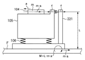
図1は、一般的な露光装置の概略構成を示す図である。床Fから除振手段106を介して定盤105が支持され、定盤105上には2次元方向(XY方向)に移動可能なウエハステージ104が支持されている。不図示の本体支持部材により、ウエハステージ104の上方に投影光学系103が支持され、更にその上方にレチクルステージ102が支持される。レチクルステージ102はレチクルRを支持し、レチクルステージ102の上方には露光光を供給するための照明系101が配置されている。
FIG. 1 is a view showing a schematic configuration of a general exposure apparatus. A
以上の構成においてウエハステージ104は不図示のウエハ搬送系で供給されたウエハWを搭載して、不図示のXY駆動機構により定盤105上をXY方向に移動する。露光動作において、ウエハステージ104はXY駆動機構により移動され、レチクルRに対する目標位置(露光位置)へウエハWが位置決めされる。位置決めされた後、レチクルRの像がウエハWに焼き付けられる。焼き付けを終えるとウエハWの次の露光位置への露光を行うべく、ウエハステージ103が駆動される。図1の露光装置は、以上の動作を繰り返すことにより、一枚のウエハW全体にレチクルの像を焼き付ける。
In the above configuration, the
上述のような露光装置においては、生産性を高めるためにウエハステージ104の移動時間や露光時間を短くする必要がある。ウエハステージ104の移動時間を短くするためには、移動時の加減速度を増加させなければならない。一方、後処理工程の生産性を高めるためにウエハWの径を大きくする必要があり、これに伴ってウエハチャック、ウエハステージ104の質量が増加の一途をたどっている。
In the exposure apparatus as described above, it is necessary to shorten the movement time and exposure time of the
このような露光装置において、ステージを駆動すると、ステージの加減速に伴う慣性力の反力が生じ、これが定盤105に伝わると定盤105の振動を引き起こす原因となる。このような振動により露光装置の機構系の固有振動が励起されて高周波振動が発生し、高速、高精度な位置決めが妨げられる可能性がある。従って、従来より、このような反力に関する問題を解決するためにいくつかの提案がなされている。例えば、特許文献1に記載された装置は、ステージを駆動するためのリニアモータの固定子をステージ定盤とは独立して床で支持することで、反力によるステージ定盤の振動を防止する。また、特許文献2に記載された装置は、ウエハステージ及び投影レンズを支持するマシンフレームに対して、水平方向に発生するアクチュエータの力によって、ステージの駆動に伴う反力と同等の補償力を付与し、反力による装置の振動を軽減する。
In such an exposure apparatus, when the stage is driven, a reaction force of inertia force accompanying the acceleration / deceleration of the stage is generated, and if this is transmitted to the
しかしながら、上記のいずれの従来技術においても、ステージ装置自体の揺れは軽減できるものの、ステージの駆動に伴う反力は、直接床に対して伝達されるか、もしくは実質的に床と一体とみなせる部材を介して床に対して伝達されてしまう。これにより床が加振され、露光装置の周辺に設置される装置に振動を与え、悪影響を及ぼす可能性がある。通常、露光装置を設置する床は20〜40Hz程度の固有振動数を持っている。露光装置の動作に伴って床が有するこのような固有振動数の振動が励起された場合、周辺の装置への悪影響は大きなものになる。 However, in any of the above prior arts, although the swing of the stage device itself can be reduced, the reaction force accompanying the drive of the stage is directly transmitted to the floor or can be regarded as substantially integral with the floor. It will be transmitted to the floor through. As a result, the floor is vibrated, and vibrations may be applied to an apparatus installed around the exposure apparatus, which may have an adverse effect. Usually, the floor on which the exposure apparatus is installed has a natural frequency of about 20 to 40 Hz. When such a vibration of the natural frequency of the floor is excited in accordance with the operation of the exposure apparatus, the adverse effects on the peripheral apparatuses become large.
昨今、処理速度(スループット)の向上に伴うステージ加速度は増加の一途であり、更にレチクルや基板の大型化に伴ってステージ質量も増大している。このため、[移動体の質量]×[加速度]で定義される駆動力は非常に大きなものとなり、その反力も膨大なものとなっている。このような反力の増大に伴い、反力による設置床の加振は無視できない問題となってきている。 In recent years, the stage acceleration accompanying the improvement of the processing speed (throughput) is steadily increasing, and the mass of the stage is also increasing as the size of the reticle and the substrate is increased. For this reason, the driving force defined by [mass of moving body] × [acceleration] is very large, and the reaction force is enormous. As the reaction force increases, the vibration of the installation floor due to the reaction force has become a problem that cannot be ignored.
また、装置の大型化も著しくなり、数多くの製造装置が設置される製造工場内での占有設置面積の増大が問題として顕在化しつつある。更に、上述のような装置から床に伝わる振動が大きいと、その振動の影響を他の装置が受けないようにするために装置間の距離を大きくする必要が生じる。このように、装置の大型化、装置間隔の確保により、各装置が事実上占有する面積が非常に増大してしまう。 In addition, the size of the apparatus has increased significantly, and an increase in the occupied installation area in a manufacturing factory where many manufacturing apparatuses are installed is becoming a problem. Furthermore, if the vibration transmitted from the device as described above to the floor is large, it is necessary to increase the distance between the devices in order to prevent other devices from being affected by the vibration. As described above, due to the increase in the size of the device and the securing of the device interval, the area actually occupied by each device is greatly increased.
一般に、床Fと定盤105の間には除振手段106を設けてはいるが、従来の反力受け装置ではステージ104の駆動の反力が床面へ伝達することを避けることができない。例えば、ステージ104のXY面内の移動により生じるX軸及びY軸まわりのモーメントは床Fに伝達されてしまう。
In general, the vibration isolation means 106 is provided between the floor F and the
また、図2に示すような、除振手段212とポスト221の組み合わせにより、床Fへの振動の伝達を低減する構成が提案されている。図2では、定盤105と床Fの間に除振手段106が設けられ、床Fと定盤105をポスト221を介して固定することにより、定盤105における振動が床へ伝達されるのを低減している。しかしながら、このような構成をもってしてもステージの駆動によって生じる反力が床Fに伝わることを回避できない。
Moreover, the structure which reduces the transmission of the vibration to the floor F by the combination of the vibration isolator 212 and the
図2に示すように、質量mのステージ104が加速度aで移動すると、床面には平面内力m・aとモーメント力M=L・m・aが作用する。ここで、Lは移動ステージの重心位置と床面との距離である。一般に、床面は平面内力に対する剛性は大きいが、モーメント力に対する剛性が小さいため、上述したモーメント力M=L・m・aによって床振動が引き起こされる。この床振動がその装置自体や周りの装置の動作に悪影響を及ぼす。
As shown in FIG. 2, when the
本出願人はステージを支持する定盤の重心とステージの重心とが異なる駆動装置においては、外部に伝達される力を軽減する反力カウンタを設けることが有効であると考えている。しかしながら、反力カウンタを備えた装置でもステージと定盤の重心がYZ平面またはZX平面で一致していないと、それぞれX軸周り、Y軸周りのモーメントが発生し、これらが床に伝達してしまう。 The present applicant considers that it is effective to provide a reaction force counter that reduces the force transmitted to the outside in a driving device in which the center of gravity of the surface plate supporting the stage differs from the center of gravity of the stage. However, even in a device equipped with a reaction force counter, if the center of gravity of the stage and the surface plate do not coincide with each other on the YZ plane or ZX plane, moments around the X axis and Y axis are generated and transmitted to the floor. End up.
ステージを支持する定盤の重心とステージの重心とが異なる駆動装置において、ステージの移動によって発生するモーメントを軽減または相殺する方法として、特許文献3に記載された装置では回転体を用いている。
しかし回転体では例えば、X軸周りのモーメントを発生させる時に、YZ平面のY方向とZ方向それぞれに回転体の直径分の設置面積を確保することが必要となる。このためどちらか1方向の長さに制限があるような空間に回転体を設置する場合には、回転体の直径が制限されてしまう。この場合、直径の小さな回転体で必要なモーメントを発生させなければならなくなる。直径の小さな回転体で大きなモーメントを発生させようとすると、慣性モーメントが小さいため角加速度が大きくなり回転速度が非常に大きくなる。一般にモータには速度の制限があり、また小さな体積のモータを高速回転させようとして大きな電流を流すと発熱も非常に大きくなってしまう。更に、回転体の重心が回転軸と完全に一致していないと、高速に回転した際に高い周波数の振動が発生するという問題も生じる。 However, in the rotating body, for example, when generating a moment around the X axis, it is necessary to secure an installation area corresponding to the diameter of the rotating body in each of the Y direction and the Z direction of the YZ plane. Therefore when installing the rotating body in a space that is limited to the length of either one direction, the diameter of the rotating body is restricted. In this case, a necessary moment must be generated by a rotating body having a small diameter. If an attempt is made to generate a large moment with a rotating body having a small diameter, the moment of inertia is small, so the angular acceleration increases and the rotational speed becomes very large. Generally, the motor has a speed limit, and if a large current is applied to rotate a small volume motor at high speed, the heat generation becomes very large. Furthermore, if the center of gravity of the rotating body does not completely coincide with the rotation axis, there is a problem that high-frequency vibration occurs when the rotating body rotates at high speed.
本発明は、上記の課題に鑑みてなされたものであり、ステージの駆動に伴う駆動反力を、効果的に相殺し、駆動反力の影響を低減することを目的とする。特に、ステージの駆動によって発生する駆動平面に平行な軸回りのモーメント反力を効果的に相殺又はその影響を低減可能とすることを目的とする。 The present invention has been made in view of the above-described problems, and an object of the present invention is to effectively cancel the driving reaction force accompanying the driving of the stage and reduce the influence of the driving reaction force. In particular, it is an object of the present invention to effectively cancel or reduce the influence of a moment reaction force around an axis parallel to a drive plane generated by driving a stage.
上記の目的を達成するための本発明のステージ装置は以下の構成を備える。即ち、
定盤と、
前記定盤の表面上を移動可能なステージと、
前記表面に対して鉛直な方向へ移動する質量体を有し、前記質量体の移動によって前記定盤に慣性力を付与する第1付与手段とを備え、
前記ステージの移動により前記定盤に発生する、前記表面に平行な軸まわりの回転方向の力を軽減するように、前記ステージの移動に応じて前記第1付与手段における前記質量体の鉛直方向への移動を制御する制御手段とを備え、
前記第1付与手段は、鉛直な方向へ移動する質量体を複数有し、
前記制御手段は、前記複数の質量体の前記鉛直方向への推力の総和が0となるように前記質量体の鉛直方向への移動を制御する。
In order to achieve the above object, a stage apparatus of the present invention comprises the following arrangement. That is,
A surface plate,
A stage movable on the surface of the surface plate;
A mass body that moves in a direction perpendicular to the surface; and a first imparting unit that imparts an inertial force to the surface plate by the movement of the mass body,
In response to the movement of the stage, in the vertical direction of the mass body according to the movement of the stage so as to reduce the force in the rotational direction around the axis parallel to the surface, which is generated on the surface plate by the movement of the stage. Control means for controlling the movement of the
The first applying means has a plurality of mass bodies that move in a vertical direction,
Wherein the control means controls the movement in the vertical direction of the vertical thrust of the sum of the direction 0 and Do that as the mass of said plurality of mass bodies.
また、本発明によれば、上記ステージ装置の制御方法、上記ステージ装置を用いた露光装置、該露光装置を用いたデバイス製造方法が提供される。 The present invention also provides a method for controlling the stage apparatus, an exposure apparatus using the stage apparatus, and a device manufacturing method using the exposure apparatus.
本発明によれば、ステージの駆動に伴う駆動反力を効果的に相殺し、駆動反力の影響を低減することが可能となる。特に、ステージの駆動によって発生する駆動平面に平行な軸回りのモーメント反力が相殺される、又はその影響が低減される。 According to the present invention, it is possible to effectively cancel the driving reaction force accompanying the driving of the stage and reduce the influence of the driving reaction force. In particular, the moment reaction force about the axis parallel to the drive plane generated by driving the stage is canceled or its influence is reduced.
以下、添付の図面を参照して本発明の好適な実施形態を説明する。 Hereinafter, preferred embodiments of the present invention will be described with reference to the accompanying drawings.
<第1実施形態>
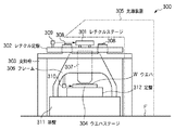
図3は、本実施形態による走査型露光装置の概略構成を示す図である。レチクルステージ301を支持するレチクル定盤302は、床面Fに直接固定された支持枠303に支持される。また、レチクルステージ301上のレチクルを経てウエハステージ304上のウエハWを露光する露光光は、破線で示す光源装置304から発生される。フレーム306はレチクルステージ301とウエハステージ304の間に投影光学系307を支持する。308はレチクルステージ301を加速および減速するリニアモータの固定子である。レチクルステージ301はレチクル定盤302上を移動する。基盤311は床Fに固定され、基盤311の上に定盤312が固定されている。ウエハステージ304は定盤312の上を移動する。
<First Embodiment>
FIG. 3 is a view showing a schematic configuration of the scanning exposure apparatus according to the present embodiment. The reticle surface plate 302 that supports the reticle stage 301 is supported by a support frame 303 that is directly fixed to the floor surface F. Further, exposure light for exposing the wafer W on the wafer stage 304 through the reticle on the reticle stage 301 is generated from a light source device 304 indicated by a broken line. The frame 306 supports the projection
なお、ウエハステージ304は、駆動部によってレチクルステージ301と同期して走査される。レチクルステージ301とウエハステージ304の走査中、両者の位置はそれぞれ干渉計309、310によって継続的に検出され、レチクルステージ301とウエハステージ309の駆動部にそれぞれフィードバックされる。これにより、両者の走査開始位置を正確に同期させるとともに、定速走査領域の走査速度を高精度で制御することができる。
The wafer stage 304 is scanned in synchronization with the reticle stage 301 by the drive unit. During scanning of reticle stage 301 and wafer stage 304, the positions of both are continuously detected by
図4は本実施形態によるステージ装置の要部の概略構成を示す斜視図である。図4においては、ステージ装置としての説明のため、ステージや定盤等の部材に新たな参照番号を付している。図4のステージ装置を図3のウエハステージ系に適用した場合、ステージ1は図3のウエハステージ304に対応し、定盤5は定盤312に対応し、床8は基盤311及び床Fに対応する。尚、座標系は、定盤5の上面の水平面内にXY軸を、XY軸と直交する方向にZ軸を定義する。ステージ1は定盤5の上面を駆動平面として移動する。
FIG. 4 is a perspective view showing a schematic configuration of a main part of the stage apparatus according to the present embodiment. In FIG. 4, for reference as a stage device, members such as a stage and a surface plate are given new reference numbers. 4 is applied to the wafer stage system of FIG. 3, the stage 1 corresponds to the wafer stage 304 of FIG. 3, the
床8の上に定盤5が固定され、定盤5の上にエアスライドを介してステージ1が定盤5の上面に沿ってXY方向に2自由度に移動自在に支持されている。ステージ1はステージアクチュエータ2と連結されている。ステージアクチュエータ2は平面パルスサーボモータであり、定盤5の上面に設けられた櫛歯との間で磁気回路を構成して、ステージ1の推力を発生する。このため、ステージ1の移動反力は定盤5に伝達される。
A
定盤5は、内部に反力カウンタ(質量体)3−1〜3−4(以下、反力カウンタ3−1〜3−4を総称する場合は反力カウンタ3と記載する)を有する。反力カウンタ3は、反力カウンタアクチュエータ4により、定盤5の内部でZ方向に移動可能なように配置されている。そして、反力カウンタアクチュエータ4は、定盤5によって支持されている。尚、本実施形態では、定盤5の内部に、FL反力カウンタ3−1、FR反力カウンタ3−2、BL反力カウンタ3−3、BR反力カウンタ3−4が設置されている。上述したように、夫々の反力カウンタは定盤5に連結された反力カウンタアクチュエータ4によってZ方向に駆動されるため反力カウンタの移動反力は定盤5に伝達される。
The
一般に、反力カウンタの推力軸がYZ平面から見てもZX平面から見ても定盤の重心上にないときに、反力カウンタをZ軸方向に駆動させると、YZ平面、ZX平面両方にモーメントを発生させることができる。従って、3つ以上の反力カウンタがあり、夫々の推力軸がXY平面から見て1直線状に無く、且つ、YZ平面及びZX平面から見て定盤の重心上に無い場合、X軸周りとY軸周りの両方に任意の大きさのモーメントを発生させることができる。よって、それら反力カウンタのZ軸方向の駆動により、ステージ1のXY平面内での任意の駆動によって発生するX軸周りとY軸周りのモーメントの両方を同時に軽減または相殺することが可能となる。本実施形態では、ステージ1の移動により生じた、定盤5から床8に伝わるモーメントを、4つの反力カウンタ3を用いて軽減し、ステージの駆動反力を軽減する。
Generally, when the thrust axis of the reaction force counter is not on the center of gravity of the surface plate when viewed from the YZ plane or the ZX plane, driving the reaction force counter in the Z-axis direction results in both the YZ plane and the ZX plane. Moments can be generated. Therefore, if there are three or more reaction force counters, and each thrust axis is not linear when viewed from the XY plane and is not on the center of gravity of the surface plate when viewed from the YZ and ZX planes, And a moment of any magnitude can be generated around the Y axis. Therefore, by driving these reaction force counters in the Z-axis direction, it is possible to simultaneously reduce or cancel both the X-axis and Y-axis moments generated by the arbitrary driving of the stage 1 in the XY plane. . In the present embodiment, the moment transmitted from the
図5を用いてZ方向に反力カウンタ3を駆動することにより、ステージの駆動反力によるモーメントを軽減、相殺する方法の原理を説明する。
The principle of a method for reducing and canceling the moment due to the driving reaction force of the stage by driving the
ステージ1がX方向にFx_stgの推力で移動するとき、Y軸右回りを正としたモーメントの釣り合いを考える。図5において、ステージ1の推力軸2aとステージ1の重心1aとの距離をLz_stgとする。また、推力軸2aと定盤5の重心5aとの距離をLz_baseとする。更に、ステージ1が定盤5に対して与えるモーメントFx_stg×Lz_stgをQy_stg、ステージ推力の反力によって定盤に発生するモーメントFx_stg×Lz_baseをQy_base、反力カウンタ3が定盤に対して与えるモーメントをQy_cntとする。
When the stage 1 moves in the X direction with a thrust of Fx_stg, consider the balance of moments with the Y axis clockwise as positive. In FIG. 5, the distance between the
ステージ1の推力軸2aとステージ1の重心1aとの距離Lz_stgを用いて、ステージ1の内部のモーメントの釣り合いは、次の式(1)のように表される。
Qy_stg−Fx_stg・Lz_stg=0 …(1)
Using the distance Lz_stg between the
Qy_stg−Fx_stg · Lz_stg = 0 (1)
また定盤5でのモーメントの釣り合いは、推力軸2aと定盤5の重心5aとの距離Lz_baseを用いて、次の式(2)のように表される。
Qy_base−Fx_stg・Lz_base−Qy_stg+Qy_cnt=0 …(2)
Also, the balance of moments on the
Qy_base−Fx_stg · Lz_base−Qy_stg + Qy_cnt = 0 (2)
ここで、Qy_base=0とするための、即ち、床へのモーメント(Y軸まわりのモーメント)の伝達を無くすための、反力カウンタ3が発生すべきモーメントは次のように計算される。
Qy_cnt=Fx_stg・(Lz_stg+Lz_base) …(3)
Here, the moment that should be generated by the
Qy_cnt = Fx_stg · (Lz_stg + Lz_base) (3)
同様にX軸まわりのモーメントが床へ伝達しないように反力カウンタ3が発生すべきモーメントは次の式(4)のように求まる。
Qx_cnt=Fy_stg・(Lz_stg+Lz_base) …(4)
Similarly, the moment to be generated by the
Qx_cnt = Fy_stg · (Lz_stg + Lz_base) (4)
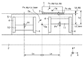
ここでLz=Lz_stg+Lz_baseとし、図6に示すように4つの反力カウンタ3−1〜3−4(の各重心)が定盤5の重心5aからX方向にLx、Y方向にLyの位置に対角に配置される構成を考える。今、FL反力カウンタ3−1、FR反力カウンタ3−2、BL反力カウンタ3−3、BR反力カウンタ3−4のそれぞれのZ方向の推力をFfl、Ffr、Fbl、Fbrとする。
Here, Lz = Lz_stg + Lz_base, and as shown in FIG. 6, four reaction force counters 3-1 to 3-4 (each center of gravity) are Lx in the X direction from the
この場合、Y軸まわりのモーメントの釣り合いは、式(3)、式(4)から次のように表される。
(Ffr+Ffl−Fbr−Fbl)・Lx=Fx_stg・Lz …(5)
In this case, the balance of moments about the Y axis is expressed as follows from equations (3) and (4).
(Ffr + Ffl-Fbr-Fbl) · Lx = Fx_stg · Lz (5)
同様に、X軸まわりのモーメントの釣り合いは次のように表される。
(Ffr+Fbr−Ffl−Fbl)・Ly=Fy_stg・Lz …(6)
Similarly, the balance of moments about the X axis is expressed as follows.
(Ffr + Fbr-Ffl-Fbl) · Ly = Fy_stg · Lz (6)
また、反力カウンタが床に対して力のz成分が伝達しないようにすることも重要であるので、4つの反力カウンタのZ方向推力の合計がちょうど0になるように次の式(7)の条件のもとで駆動する。
Ffr+Ffl+Fbr+Fbl=0 …(7)
It is also important that the reaction force counter does not transmit the z component of the force to the floor, so that the total of the Z direction thrusts of the four reaction force counters is exactly 0 (7 ) Drive under the conditions of
Ffr + Ffl + Fbr + Fbl = 0 (7)
反力カウンタは4つあるので推力の自由度は4であり、満たすべき条件式は3つ(式(5)〜(7))なので、これらを満足する反力カウンタ3の駆動方法は無限に存在することになる。それらのうちの1例を下記に示す。尚、以下では、Fx_stgをFx、Fy_stgをFyと記載している。
Ffl=(LyFx+LxFy)・Lz/4LxLy
Ffr=−(LyFx−LxFy)・Lz/4LxLy
Fbl=(LyFx−LxFy)・Lz/4LxLy
Fbr=−(LyFx+LxFy)・Lz/4LxLy …(8)
Since there are four reaction force counters, the degree of freedom of thrust is 4, and the conditional expressions to be satisfied are three (formulas (5) to (7)). Therefore, the driving method of the
Ffl = (LyFx + LxFy) ・ Lz / 4LxLy
Ffr = − (LyFx−LxFy) ・ Lz / 4LxLy
Fbl = (LyFx−LxFy) ・ Lz / 4LxLy
Fbr = − (LyFx + LxFy) · Lz / 4LxLy (8)
以上の数式を満たすように制御器9が反力カウンタアクチュエータ4を制御する。尚、反力カウンタアクチュエータ4としてはリニアモータ、パルスモータ、エアアクチュエータなどが考えられる。
The
又、地球上では重力があるので、重力加速度をg、反力カウンタ3の重量をM_cntとすると、反力カウンタには常に−M_cnt・gという力がZ方向にかかることになる。この力の大きさは一定であるので、これを補償する機構を設けることで反力カウンタアクチュエータ4は反力カウンタ3が移動するために必要な推力のみを発生させれば良くなる。このような自重を補償する機構としては空気圧、油圧、磁石、バネ等が考えられる。
Further, since there is gravity on the earth, if the acceleration of gravity is g and the weight of the
また、例えば、図4、図6に示したように反力カウンタ3を配置し、上記式(8)に示す推力で反力カウンタ3を駆動する場合、対角に配置された反力カウンタの推力は絶対値が等しくかつ方向が逆になっている。従って、FL反力カウンタ3−1とBR反力カウンタ3−4、FR反力カウンタ3−2とBL反力カウンタ3−3をワイヤなどで連結し上方から吊り下げることで自重分を打ち消すことができる。或は、油圧又は空気圧シリンダなどで連結して下から支えることで自重分を打ち消すことももちろん可能である。
Further, for example, when the
図12に、反力カウンタの自重補償の機構の一例を示す。定盤5に組み込まれた反力カウンタ3において、質量体10,11は反力カウンタアクチュエータ4により上下に駆動される。自重補償機構は、例えば、パイプ122により連結されたエアシリンダ121により構成される。もちろん、シリンダは油圧等の流体を用いたシリンダであってもよい。また、例えば、エアシリンダの変わりに、エアもしくは液体を充填した蛇腹構造を用いることもできる。
FIG. 12 shows an example of a self-weight compensation mechanism for the reaction force counter. In the
更に、ステージがZ方向にも力Fzを発生させる場合、−Fz/4の力を各反力カウンタが均等に発生させることで、モーメントに関する釣り合いを保ちつつZ方向の力も相殺することができる。これを数式で表すと次のようになる。
Ffl=(LyFx+LxFy)Lz/4LxLy−Fz/4
Ffr=−(LyFx−LxFy)Lz/4LxLy−Fz/4
Fbl=(LyFx−LxFy)Lz/4LxLy−Fz/4
Fbr=−(LyFx+LxFy)Lz/4LxLy−Fz/4 …(9)
Further, when the stage generates the force Fz also in the Z direction, each reaction force counter uniformly generates a force of −Fz / 4, so that the force in the Z direction can be canceled while maintaining a balance regarding the moment. This is expressed by the following formula.
Ffl = (LyFx + LxFy) Lz / 4LxLy−Fz / 4
Ffr =-(LyFx-LxFy) Lz / 4LxLy-Fz / 4
Fbl = (LyFx−LxFy) Lz / 4LxLy−Fz / 4
Fbr =-(LyFx + LxFy) Lz / 4LxLy-Fz / 4 (9)
上記によれば、モーメントの床など外部の部材への伝達がある程度許容される場合に、モーメントを完全に相殺するために必要な推力に対して、大きなまたは小さな推力とすることができることを表している。従って、外部に伝達されるモーメントを許容される範囲内に抑えつつ、反力カウンタのストローク中心方向に力を発生させる。即ち、ストロ−クエンドに近づく方向の力は必要推力に対して小さく、ストロークエンドから離れる方向の力は必要推力に対して大きくすることで、反力カウンタのZ方向のストロークを短くすることができる。 According to the above, when transmission of the moment to an external member such as a floor is allowed to some extent, it is possible to make the thrust larger or smaller than the thrust necessary to completely cancel the moment. Yes. Therefore, a force is generated in the direction of the stroke center of the reaction force counter while suppressing the moment transmitted to the outside within an allowable range. That is, the force in the direction approaching the stroke end is small with respect to the required thrust, and the force in the direction away from the stroke end is increased with respect to the required thrust, so that the Z-direction stroke of the reaction force counter can be shortened. .
図7は、制御器9の、ステージアクチュエータ2及び反力カウンタアクチュエータ4に係る制御構成の一例を示すブロック図である。装置制御部91は当該露光装置の全体を制御し、露光処理のためのステージ1の位置を指示するステージ位置指令値を発生する。ステージ制御器92は、ステージ位置指令値とステージアクチュエータ2からのフィードバック信号に基づいてウエハステージ1の駆動に必要な推力を算出することによりステージ推力指令値(Fx、Fy)を生成し、これをステージアクチュエータ2に送る。ステージアクチュエータ2はステージ推力指令値に従ってウエアステージ1を駆動する。
FIG. 7 is a block diagram illustrating an example of a control configuration of the
反力カウンタ位置指令値生成部93は、装置制御部91が発生したステージ1の位置指令値に基づいて、反力カウンタ3の位置指令値を生成する。反力カウンタ位置指令値生成部93は、ステージ位置指令値や、反力カウンタ3と重心5aとの距離(Lx、Ly)、カウンタの重量(M_cnt)、ステージ1の重量に基づいて反力カウンタ3の位置指令値を生成する。反力カウンタ制御器95は、反力カウンタ位置指令値生成部93が生成した位置指令値と反力カウンタアクチュエータ4からのフィードバック信号に基づいて反力カウンタ3の推力指令値を生成する。反力カウンタ推力指令値生成部94は、ステージ制御器92が発生したステージ推力指令値(Fx、Fy)と反力カウンタ3と重心5aとの距離(Lx、Ly)に基づいて反力カウンタの推力指令値を生成する。反力カウンタ制御器95及び反力カウンタ推力指令値生成部94から出力される推力指令値は合成され、反力カウンタアクチュエータ4に供給される。反力カウンタアクチュエータ4は、この合成された推力指令値に基づいて反力カウンタ3を駆動する。こうして、上記式(8)に示したFfl、Ffr、Fbl、Fbrを反力カウンタ3に発生させる。
The reaction force counter position command
尚、式(9)を採用する場合は、反力カウンタ推力指令値生成部94はステージ制御器92からFzの提供を受け、推力指令値を生成する。こうして、反力カウンタの位置と推力によりステージ1の反力を相殺するとともに、駆動範囲が決められたストローク内に収まるように、反力カウンタが駆動される。
In the case where the equation (9) is adopted, the reaction force counter thrust command
以上のように、第1実施形態によれば、ステージ1の移動により定盤5に発生する、X,Y軸まわり(ステージ1の移動平面に平行な軸まわり)の回転方向の力を軽減するように、ステージ1の移動に応じて反力カウンタ3が鉛直方向へ移動される。このため、ステージ1の移動により定盤5に生じるX軸及びY軸まわりの回転力が相殺もしくは減少されることになり、床へ伝わる振動が低減される。
As described above, according to the first embodiment, the force in the rotational direction around the X and Y axes (around the axis parallel to the moving plane of the stage 1) generated on the
<第2実施形態>
第1実施形態では、ステージ1の駆動によって生じるX軸及びY軸まわりのモーメントを打ち消すと共に、Z方向に加わる反力を相殺可能な構成を説明した。第2実施形態では、更に、ステージ1の駆動によるX方向、Y方向の並進力及びZ軸まわりのモーメントを打ち消す構成を加える。
Second Embodiment
In the first embodiment, a configuration has been described in which moments around the X axis and the Y axis generated by driving the stage 1 are canceled and the reaction force applied in the Z direction can be canceled. In the second embodiment, there is further added a configuration in which the translational forces in the X and Y directions and the moment around the Z axis due to the drive of the stage 1 are canceled.
図8は第2実施形態による反力カウンタの配置例を示す図である。第2実施形態では、定盤5の内部に4種類の反力カウンタを構成している。反力カウンタ3−1〜3−4は、第1実施形態で説明したように、Z方向に移動可能であり、X軸まわりのモーメントとY軸まわりのモーメントを相殺し、また、Z方向の力も相殺する。XF反力カウンタ(質量体)6−1,XB反力カウンタ(質量体)6−2は、それぞれ、X方向に移動可能であり、ステージ1の駆動によって生じるX並進力を相殺する。YL反力カウンタ(質量体)6−3及びYR反力カウンタ(質量体)6−4は、それぞれY方向に移動可能であり、ステージ1の駆動によって生じるY並進力を相殺する。WZL反力カウンタ(質量体)6−5及びWZR反力カウンタ(質量体)6−6は、それぞれ、Y方向に移動可能であり、ステージ1の駆動によって生じるZ軸まわりのモーメントを相殺する。
FIG. 8 is a diagram showing an example of the arrangement of reaction force counters according to the second embodiment. In the second embodiment, four types of reaction force counters are configured inside the
ここで、ステージ1のX方向推力をFx_stg、Y方向推力をFy_stg、定盤5の重心5aを原点としたステージ1(重心1a)のXY座標を(Xstg、Ystg)とする。また、WZL反力カウンタ6−5とWZR反力カウンタ6−6のY方向座標(重心位置)をYwzl、Ywzrとする。また、XF反力カウンタ6−1とXB反力カウンタ6−2のX方向推力の合計をFx_cntx、YL反力カウンタ6−3とYR反力カウンタ6−4のY方向推力の合計をFy_cntyとする。更に、WZL反力カウンタ6−5のY方向推力をFy_cntwzl、WZR反力カウンタ6−6のY方向推力をFy_cntwzrとする。すると、それぞれの反力カウンタの発生すべき推力は次のように表される。
Here, the X-direction thrust of the stage 1 is Fx_stg, the Y-direction thrust is Fy_stg, and the XY coordinates of the stage 1 (center of gravity 1a) with the center of
Fx_cntx=Fx_stg
Fy_cnty=Fy_stg
Fy_cntwzr=(Fx_stg・Ystg−Fy_stg・Xstg)/2Ywzl
Fy_cntwzr=(Fx_stg・Ystg−Fy_stg・Xstg)/2Ywzr …(10)
Fx_cntx = Fx_stg
Fy_cnty = Fy_stg
Fy_cntwzr = (Fx_stg • Ystg−Fy_stg • Xstg) / 2Ywzl
Fy_cntwzr = (Fx_stg · Ystg−Fy_stg · Xstg) / 2Ywzr (10)
尚、FL反力カウンタ3−1、FR反力カウンタ3−2、BL反力カウンタ3−3、BR反力カウンタ3−4の推力については、第1実施形態(式(8)或は式(9))と同様である。 The thrusts of the FL reaction force counter 3-1, the FR reaction force counter 3-2, the BL reaction force counter 3-3, and the BR reaction force counter 3-4 are described in the first embodiment (equation (8) or equation). The same as (9)).
即ち、制御器9により、XF反力カウンタ6−1とXB反力カウンタ6−2のX方向推力の合計を式(10)のFx_cntxに制御することで、ステージ1の移動によって生じるX方向の並進力が相殺される。また、YL反力カウンタ6−3とYR反力カウンタ6−4のY方向推力の合計を式(10)のFy_cntyに制御することで、ステージ1の移動によって生じるX方向の並進力が相殺される。また、WZL反力カウンタ6−5のY方向推力を式(10)のFy_cntwzlに、WZR反力カウンタ6−6のY方向推力を式(10)のFy_cntwzrに制御することで、ステージ1の移動によって生じるZ軸まわりの回転力(モーメント)が相殺される。
以上のように第2実施形態によれば、第1実施形態の効果に加えて、ステージ1の駆動に伴うXY面内の並進力やZ軸まわりのモーメントを打ち消すことができる。
That is, the
As described above, according to the second embodiment, in addition to the effects of the first embodiment, it is possible to cancel the translational force in the XY plane and the moment around the Z axis that accompany the drive of the stage 1.
<第3実施形態>
次に、第3実施形態を説明する。第3実施形態では、ステージ1の移動により生じる並進力の相殺に反力カウンタを用いない。また、ステージ1の移動により生じるZ軸まわりのモーメントを定盤5内に配置されたロータにより相殺する。なお、ロータは円盤状の質量体であり、固定子が定盤5に固定され、ロータ(回転子)が定盤5の内部に設けられて回転する構成となっている。
<Third Embodiment>
Next, a third embodiment will be described. In the third embodiment, the reaction force counter is not used to cancel the translational force generated by the movement of the stage 1. Further, the moment around the Z axis caused by the movement of the stage 1 is canceled by the rotor arranged in the
まず、定盤5は床8に対してXY方向に自由に移動可能に構成されており、ステージ1の移動によって定盤5に伝達されるX方向の力FxとY方向の力Fyを受けて定盤5が移動することで、力の床への伝達を防ぐ。
即ち、定盤5は床を平面的に移動可能なように支持されており、ステージ1の推力の反力で定盤が移動する。床から支持された移動しない部材に測定器(例えば、レーザ干渉計)を設け、床座標基準でステージ1の位置を測定することで、定盤5が移動しても正しい位置決めが可能となる。また、定盤5が移動するため、ステージ1の推力は定盤5の加速度分だけ余分に必要となる。
First, the
That is, the
尚、上記のステージ1と定盤5に関して、床座標系から見た加速度の関係は次の(11a)ようになる。
Fx_base=Fx_stg
m_base・Acc_base=m_stg(Acc_stg+Acc_base) …(11a)
尚、上記式において、Acc_baseとAcc_stgはそれぞれ床座標系から見た定盤5とステージ1の加速度の絶対値である。
定盤5が移動するため、ステージ1の必要推力はステージ1と定盤5の相対化速度となる。換言すると、ステージ1が床座標系から見てAcc_stgで移動する反力によって定盤5に生じる加速度は、
Acc_base=Acc_stg・m_stg/(m_base−m_stg) …(11b)
と表される。
In addition, regarding the above-mentioned stage 1 and the
Fx_base = Fx_stg
m_base · Acc_base = m_stg (Acc_stg + Acc_base) (11a)
In the above equation, Acc_base and Acc_stg are the absolute values of the acceleration of the
Since the
Acc_base = Acc_stg · m_stg / (m_base−m_stg) (11b)
It is expressed.
また、定盤5の内部には反力カウンタと、ロータが配置される。反力カウンタは、第1実施形態と同様に、Z方向に移動可能なX軸まわりのモーメントとY軸まわりのモーメントを相殺するものであり、FL反力カウンタ3−1、FR反力カウンタ3−2、BL反力カウンタ3−3、BR反力カウンタ3−4を含む。また、定盤5は4つのロータ、FLロータ(質量体)7−1、FRロータ(質量体)7−2、BLロータ(質量体)7−3及びBRロータ(質量体)7−4を含み、これらロータの回転により定盤5にZ軸まわりのモーメントを発生させることが可能である。第3実施形態では、ステージ1の移動によって定盤5に生じるX軸まわりのモーメントとY軸まわりのモーメントはZ方向に駆動される反力カウンタ3−1〜3−4によって相殺または軽減される。そして、ステージ1の移動によって定盤5に生じるZ軸まわりのモーメントはロータ7−1〜7−4によって相殺または軽減される。
A reaction force counter and a rotor are arranged inside the
ステージ1のX方向推力をFx_stg、Y方向推力をFy_stgとし、定盤5の重心5aを原点としたステージ1の重心1aのXY座標を(Xstg、Ystg)とする。また、定盤5にかかるX方向推力の合計をFx_base、Y方向推力をFx_baseとする。更に、ロータ7−1〜7−4が発生すべきZ軸まわりのモーメントをQz_roterとする。この場合、以下の式(11c)に示されるように定盤5をX,Y方向に駆動し、ロータ7−1〜7−4を駆動することにより、ステージ1の移動によるXY方向の反力とZ軸まわりのモーメントが相殺または軽減される。
The X-direction thrust of the stage 1 is Fx_stg, the Y-direction thrust is Fy_stg, and the XY coordinates of the center of gravity 1a of the stage 1 with the center of
Fx_base=Fx_stg
Fy_base=Fy_stg
Qz_roter=Fx_stg・Ystg−Fy_stg・Xstg …(11c)
Fx_base = Fx_stg
Fy_base = Fy_stg
Qz_roter = Fx_stg · Ystg−Fy_stg · Xstg (11c)
尚、ステージ1の移動によって定盤に生じるX軸周りのモーメントとY軸まわりのモーメント、及びZ方向に加わる力を相殺又は軽減するための反力カウンタ3−1〜3−4の推力は第1実施形態と同様である。 The thrust of the reaction force counters 3-1 to 3-4 for canceling or reducing the moment about the X axis and the moment about the Y axis, and the force applied in the Z direction generated on the surface plate by the movement of the stage 1 is the first. This is the same as in the first embodiment.
以上説明したように、第1〜第3実施形態によれば、Z方向に推力を発生する反力カウンタ3を用いることでステージ1の移動によって定盤に生じるX軸周りのモーメントとY軸まわりのモーメント、及びZ方向に加わる力を相殺又は軽減することができる。Z方向に移動する反力カウンタを用いるため、従来の回転体を用いた構成に比べて反力カウンタの設置スペースの自由度が高くなり、設置する場所の制限に応じた柔軟な形状変更が可能である。
As described above, according to the first to third embodiments, by using the
また、図4に示すようにXY方向に長いがZ方向に短い空間に反力カウンタを設置して、X、Y軸周りのモーメントを相殺する場合を考える。この場合、例えば反力カウンタ3をX方向に長い形状にして重量をかせぎ、モーメントを発生させた際のZ方向のストロークを短くすることが可能となる。尚、図4ではX方向に長くなるようにカウンタを配置しているが、X方向よりもY方向に長い形状となっているのであれば、Y方向に長くなるように反力カウンタを設置するようにしてもよい。
Further, as shown in FIG. 4, a case is considered in which a reaction force counter is installed in a space that is long in the XY direction but short in the Z direction to cancel moments around the X and Y axes. In this case, for example, it is possible to shorten the stroke in the Z direction when the moment is generated by making the
また、反力カウンタ3は1方向にのみ駆動されるので、駆動される部材に多少の重心の偏りがあってもそれが高い周波数の振動を引き起こすようなことはない。また、図4に示されるように、ステージ1と反力カウンタ3が定盤5によって支持されている場合に、定盤5の重心5aと反力カウンタ3の推力軸との距離Lx、Lyを長くすることが望ましい。小さな推力で大きなモーメントを発生させることができ、消費電力・発熱の面から有利であるからである。
Further, since the
以上説明したように、上記各実施形態のステージ装置によれば、反力カウンタにモーメントを発生させることによって定盤から外部に伝達されるモーメントを軽減させることができる。また、特に、平面モータが発生させるピッチングやローリングのモーメントを、Z方向へ駆動される反力カウンタにより、同時に軽減している。例えば、図6に示すように反力カウンタを配置することで、ピッチング、ローリングのモーメント(X軸、Y軸まわりのモーメント)が同時に軽減される。さらに、反力カウンタが複数あれば、反力カウンタ全体として並進力を発生させずにモーメントのみを定盤に伝達することが可能となる(式(8))。これによりステージの高精度な位置決めが可能になるほか、周囲の他の装置に床振動による外乱等の影響を軽減させることができる。 As described above, according to the stage device of each of the above embodiments, the moment transmitted to the outside from the surface plate can be reduced by generating a moment in the reaction force counter. In particular, the pitching and rolling moments generated by the planar motor are simultaneously reduced by a reaction force counter driven in the Z direction. For example, by arranging a reaction force counter as shown in FIG. 6, the pitching and rolling moments (moments about the X and Y axes) can be reduced at the same time. Furthermore, if there are a plurality of reaction force counters, only the moment can be transmitted to the surface plate without generating a translational force as a whole reaction force counter (Equation (8)). As a result, the stage can be positioned with high accuracy, and the influence of disturbances and the like caused by floor vibrations on other peripheral devices can be reduced.
更に、上記実施形態の露光装置は、上述のステージ装置を用いているため、ウエハ、レチクルの高速、高精度な位置決めが期待でき、高スループット化を図れる。また、装置自身の低振動化により、周囲の他の装置への振動による外乱等の影響を軽減させることができる。 Furthermore, since the exposure apparatus of the above embodiment uses the stage apparatus described above, high-speed and high-precision positioning of the wafer and reticle can be expected, and high throughput can be achieved. In addition, by reducing the vibration of the device itself, it is possible to reduce the influence of disturbance or the like due to vibration to other peripheral devices.
尚、上記第1〜第3実施形態では、図4のステージ装置を図3のウエハステージに適用した場合を説明したが、レチクルステージにも適用可能である。この場合、レチクルステージ301がステージ1に、レチクル定盤302が定盤5に対応する。また、指示枠303が床8に対応することになる。このように、上記実施形態のステージ装置は、ステップ・アンド・リピート型の露光装置におけるウエハステージに適用可能であり、また、ステップ・アンド・スキャン型の露光装置におけるウエハステージ及び/又はレチクルステージに適用可能である。また、上記各実施形態では反力カウンタを定盤5の内部に配置したが、定盤5の外周に反力カウンタとアクチュエータを装着した形態としてもよい。
また、上記実施形態では、定盤5に1つのステージが搭載された例を示したが、定盤5に複数のステージが設置されたような場合にも、上記各実施形態は適用可能である。その場合、複数のステージの駆動反力によるモーメントの合計を軽減、相殺するように反力カウンタ3を駆動することになる。
In the first to third embodiments, the case where the stage apparatus of FIG. 4 is applied to the wafer stage of FIG. 3 has been described, but the present invention can also be applied to a reticle stage. In this case, reticle stage 301 corresponds to stage 1 and reticle surface plate 302 corresponds to surface
Moreover, in the said embodiment, although the example with which one stage was mounted in the
<デバイス製造方法への適用>
次に上述した露光装置を利用した半導体デバイスの製造方法の実施形態を説明する。図10は半導体デバイス(ICやLSI等の半導体チップ、液晶パネル、CCD、薄膜磁気ヘッド、マイクロマシン等)の製造のフローを示す。ステップS11(回路設計)では半導体デバイスの回路設計を行う。ステップS12(レチクル製作)では設計した回路パターンを形成したレチクルを製作する。一方、ステップS13(ウエハ製造)ではシリコン等の材料を用いて基板であるウエハを製造する。ステップS14(ウエハプロセス)は前工程と呼ばれ、上記用意したレチクルとウエハを用いて、リソグラフィ技術によってウエハ上に実際の回路を形成する。次のステップS15(組立)は後工程と呼ばれ、ステップS14によって作製されたウエハを用いて半導体チップ化する工程であり、アッセンブリ工程(ダイシング、ボンディング)、パッケージング工程(チップ封入)等の工程を含む。ステップS16(検査)ではステップS15で作製された半導体デバイスの動作確認テスト、耐久性テスト等の検査を行う。こうした工程を経て半導体デバイスが完成し、これが出荷(ステップS17)される。
<Application to device manufacturing method>
Next, an embodiment of a semiconductor device manufacturing method using the above-described exposure apparatus will be described. FIG. 10 shows a manufacturing flow of a semiconductor device (a semiconductor chip such as an IC or LSI, a liquid crystal panel, a CCD, a thin film magnetic head, a micromachine, etc.). In step S11 (circuit design), a semiconductor device circuit is designed. In step S12 (reticle manufacture), a reticle on which the designed circuit pattern is formed is manufactured. On the other hand, in step S13 (wafer manufacture), a wafer as a substrate is manufactured using a material such as silicon. Step S14 (wafer process) is called a pre-process, and an actual circuit is formed on the wafer by lithography using the prepared reticle and wafer. The next step S15 (assembly) is called a post-process, and is a process for forming a semiconductor chip using the wafer produced in step S14, and is a process such as an assembly process (dicing, bonding), a packaging process (chip encapsulation), or the like. including. In step S16 (inspection), the semiconductor device manufactured in step S15 undergoes inspections such as an operation confirmation test and a durability test. Through these steps, the semiconductor device is completed and shipped (step S17).
図11は上記ウエハプロセスの詳細なフローを示す。ステップS21(酸化)ではウエハの表面を酸化させる。ステップS22(CVD)ではウエハ表面に絶縁膜を形成する。ステップS23(電極形成)ではウエハ上に電極を蒸着によって形成する。ステップS24(イオン打込み)ではウエハにイオンを打ち込む。ステップS25(レジスト処理)ではウエハに感光剤を塗布する。ステップS26(露光)では上記説明した露光装置によってレチクルの回路パターンをウエハに焼付露光する。ステップS27(現像)では露光したウエハを現像する。ステップS28(エッチング)では現像したレジスト像以外の部分を削り取る。ステップS29(レジスト剥離)ではエッチングが済んで不要となったレジストを取り除く。これらのステップを繰り返し行うことによって、ウエハ上に多重に回路パターンが形成される。本実施形態の製造方法を用いれば、高集積度の半導体デバイスを製造することができる。 FIG. 11 shows a detailed flow of the wafer process. In step S21 (oxidation), the wafer surface is oxidized. In step S22 (CVD), an insulating film is formed on the wafer surface. In step S23 (electrode formation), an electrode is formed on the wafer by vapor deposition. In step S24 (ion implantation), ions are implanted into the wafer. In step S25 (resist process), a photosensitive agent is applied to the wafer. In step S26 (exposure), the circuit pattern of the reticle is printed onto the wafer by the exposure apparatus described above. In step S27 (development), the exposed wafer is developed. In step S28 (etching), portions other than the developed resist image are removed. In step S29 (resist stripping), the resist that has become unnecessary after the etching is removed. By repeatedly performing these steps, multiple circuit patterns are formed on the wafer. If the manufacturing method of this embodiment is used, a highly integrated semiconductor device can be manufactured.
Claims (18)
前記定盤の表面上を移動可能なステージと、
前記表面に対して鉛直な方向へ移動する質量体を有し、前記質量体の移動によって前記定盤に慣性力を付与する第1付与手段とを備え、
前記ステージの移動により前記定盤に発生する、前記表面に平行な軸まわりの回転方向の力を軽減するように、前記ステージの移動に応じて前記第1付与手段における前記質量体の鉛直方向への移動を制御する制御手段とを備え、
前記第1付与手段は、鉛直な方向へ移動する質量体を複数有し、
前記制御手段は、前記複数の質量体の前記鉛直方向への推力の総和が0となるように前記質量体の鉛直方向への移動を制御する、ことを特徴とするステージ装置。 A surface plate,
A stage movable on the surface of the surface plate;
A mass body that moves in a direction perpendicular to the surface; and a first imparting unit that imparts an inertial force to the surface plate by the movement of the mass body,
In response to the movement of the stage, in the vertical direction of the mass body according to the movement of the stage so as to reduce the force in the rotational direction around the axis parallel to the surface, which is generated on the surface plate by the movement of the stage. Control means for controlling the movement of the
The first applying means has a plurality of mass bodies that move in a vertical direction,
Wherein the control means controls the movement in the vertical direction of the vertical thrust of the sum of the direction 0 and Do that as the mass of said plurality of mass bodies, the stage and wherein the.
前記制御手段は、更に、前記ステージの移動により前記定盤に発生する、前記表面に鉛直な軸に関する回転方向の力を軽減するように、前記ステージの移動に応じて前記第2付与手段における質量体の移動を制御することを特徴とする請求項1に記載のステージ装置。 It has a mass body that moves in a direction parallel to the surface, and further comprises a second imparting means for imparting an inertial force to the surface plate by the movement of the mass body,
The control means further includes a mass in the second applying means according to the movement of the stage so as to reduce a force in a rotation direction about an axis perpendicular to the surface generated on the surface plate by the movement of the stage. The stage apparatus according to claim 1, wherein the stage movement is controlled.
前記制御手段は、更に、前記ステージの移動により前記定盤に発生する、前記表面に鉛直な軸に関する回転方向の力を軽減するように、前記ステージの移動に応じて前記第3付与手段における質量体の回転を制御することを特徴とする請求項1または10に記載のステージ装置。 A mass body capable of rotating in the surface plate, further comprising third imparting means for imparting a rotational force about an axis perpendicular to the surface to the surface plate by rotation of the mass body;
The control means further includes a mass in the third applying means according to the movement of the stage so as to reduce the force in the rotational direction about the axis perpendicular to the surface generated on the surface plate by the movement of the stage. stage apparatus according to claim 1 or 10, characterized in that for controlling the rotation of the body.
前記制御手段は、前記複数のステージの移動により前記定盤に発生する、前記表面に平行な軸まわりの回転方向の合成力を軽減するように、前記ステージの移動に応じて前記第1付与手段における前記質量体の鉛直方向への移動を制御することを特徴とする請求項1に記載のステージ装置。 A plurality of stages are provided on the surface plate,
The control means is configured to reduce the combined force in the rotational direction around an axis parallel to the surface, which is generated in the surface plate by the movement of the plurality of stages, and the first applying means according to the movement of the stage. The stage apparatus according to claim 1, wherein movement of the mass body in the vertical direction is controlled.
前記定盤の表面上を互いに直交する第1及び第2方向に移動可能なステージと、 A stage movable on the surface of the surface plate in first and second directions orthogonal to each other;
前記表面に対して鉛直な方向へ移動する4つの質量体を有し、前記質量体の移動によって前記定盤に慣性力を付与する第1付与手段と、 Four mass bodies that move in a direction perpendicular to the surface, and a first imparting means that imparts inertial force to the surface plate by the movement of the mass bodies;
前記ステージの移動により前記定盤に発生する、前記表面に平行な軸まわりの回転方向の力を軽減するように、前記ステージの移動に応じて前記第1付与手段における前記質量体の鉛直方向への移動を制御する制御手段と、を備え、 In response to the movement of the stage, in the vertical direction of the mass body according to the movement of the stage so as to reduce the force in the rotational direction around the axis parallel to the surface, which is generated on the surface plate by the movement of the stage. Control means for controlling the movement of the
前記4つの質量体は、前記定盤の重心を含み前記第1方向に平行かつ前記表面に垂直な面と前記定盤の重心を含み前記第2方向に平行かつ前記表面に垂直な面の両面によって分割される4つの領域に1つずつ配置され、 The four mass bodies include a surface including the center of gravity of the surface plate and parallel to the first direction and perpendicular to the surface, and a surface including the center of gravity of the surface plate and parallel to the second direction and perpendicular to the surface. Are arranged one by one in four areas divided by
前記制御手段は、前記4つの領域のうちの対角の位置関係にある領域に配置された2つの質量体が前記定盤に付与する力の絶対値が等しくかつ付与する方向が逆になるように前記質量体の移動を制御し、 The control means is such that the absolute values of the force applied to the surface plate by the two mass bodies arranged in the diagonal positional relationship of the four regions are equal and the direction of the application is reversed. To control the movement of the mass body,
前記4つの領域のうちの対角の位置関係にある領域に配置された質量体は、ワイヤ、油圧、空気圧シリンダのいずれかによって連結されることを特徴とするステージ装置。 The stage device characterized in that the mass bodies arranged in the diagonally-positioned region of the four regions are connected by any one of a wire, a hydraulic pressure, and a pneumatic cylinder.
前記定盤の表面上を移動可能なステージと、
前記表面に対して鉛直な方向へ移動可能な質量体を有し、前記質量体の移動によって前記定盤に慣性力を付与する第1付与手段とを備えたステージ装置の制御方法であって、
前記ステージの移動により前記定盤に発生する、前記表面に平行な軸まわりの回転方向の力を軽減するように、前記ステージの移動に応じて前記第1付与手段における前記質量体の鉛直方向への移動を制御する制御工程を備え、
前記第1付与手段は、鉛直な方向へ移動する質量体を複数有し、
前記制御工程では、前記複数の質量体の前記鉛直方向への推力の総和が0となるように前記質量体の鉛直方向への移動を制御する、ことを特徴とするステージ装置の制御方法。 A surface plate,
A stage movable on the surface of the surface plate;
A control method for a stage apparatus, comprising: a mass body that is movable in a direction perpendicular to the surface; and a first imparting unit that imparts an inertial force to the surface plate by the movement of the mass body,
In response to the movement of the stage, in the vertical direction of the mass body according to the movement of the stage so as to reduce the force in the rotational direction around the axis parallel to the surface, which is generated on the surface plate by the movement of the stage. A control process for controlling the movement of the
The first applying means has a plurality of mass bodies that move in a vertical direction,
Wherein in the control step, that controls the movement in the vertical direction of the vertical thrust of the sum of the direction becomes zero as the mass of said plurality of mass bodies, the control method of the stage device, characterized in that.
前記定盤の表面上を互いに直交する第1及び第2方向に移動可能なステージと、 A stage movable on the surface of the surface plate in first and second directions orthogonal to each other;
前記表面に対して鉛直な方向へ移動する4つの質量体を有し、前記質量体の移動によって前記定盤に慣性力を付与する第1付与手段と、を備えたステージ装置の制御方法であって、 And a first applying unit that includes four mass bodies that move in a direction perpendicular to the surface, and that applies inertial force to the surface plate by the movement of the mass bodies. And
前記ステージの移動により前記定盤に発生する、前記表面に平行な軸まわりの回転方向の力を軽減するように、前記ステージの移動に応じて前記第1付与手段における前記質量体の鉛直方向への移動を制御する制御工程を備え、 In response to the movement of the stage, in the vertical direction of the mass body according to the movement of the stage so as to reduce the force in the rotational direction around the axis parallel to the surface, which is generated on the surface plate by the movement of the stage. A control process for controlling the movement of the
前記4つの質量体は、前記定盤の重心を含み前記第1方向に平行かつ前記表面に垂直な面と前記定盤の重心を含み前記第2方向に平行かつ前記表面に垂直な面の両面によって分割される4つの領域に1つずつ配置され、 The four mass bodies include a surface including the center of gravity of the surface plate and parallel to the first direction and perpendicular to the surface, and a surface including the center of gravity of the surface plate and parallel to the second direction and perpendicular to the surface. Are arranged one by one in four areas divided by
前記制御工程では、前記4つの領域のうちの対角の位置関係にある領域に配置された2つの質量体が前記定盤に付与する力の絶対値が等しくかつ付与する方向が逆になるように前記質量体の移動を制御し、 In the control step, the absolute value of the force applied to the surface plate by the two mass bodies arranged in the diagonally-positioned region of the four regions is equal and the direction of the application is reversed. To control the movement of the mass body,
前記4つの領域のうちの対角の位置関係にある領域に配置された質量体は、ワイヤ、油圧、空気圧シリンダのいずれかによって連結されていることを特徴とするステージ装置の制御方法。 A method of controlling a stage apparatus, wherein mass bodies arranged in a diagonal position relationship among the four areas are connected by any of a wire, a hydraulic pressure, and a pneumatic cylinder.
ウエハを搭載して移動するウエハステージと、
レチクルを搭載するレチクルステージと、
前記露光光により、前記レチクルステージに搭載されたレチクルパターンを前記ウエハステージ上のウエハに結像する光学系とを備え、
前記ウエハステージが請求項1乃至13のいずれか1項に記載されたステージ装置を備えていることを特徴とする露光装置。 A light source that emits exposure light;
A wafer stage that carries and moves the wafer;
A reticle stage equipped with a reticle;
An optical system that forms an image of a reticle pattern mounted on the reticle stage on the wafer on the wafer stage with the exposure light;
An exposure apparatus, wherein the wafer stage includes the stage apparatus according to any one of claims 1 to 13 .
露光された基板を現像する工程とを有することを特徴とするデバイス製造方法。 A step of exposing a pattern to a substrate using the exposure apparatus according to claim 16;
And a step of developing the exposed substrate.
請求項16に記載の露光装置を用いて基板に潜像パターンが形成された基板を用意する工程と、
前記潜像パターンを現像する工程とを含むことを特徴とするデバイス製造方法。 A device manufacturing method comprising:
Preparing a substrate having a latent image pattern formed on the substrate using the exposure apparatus according to claim 16;
And a step of developing the latent image pattern.
Priority Applications (4)
| Application Number | Priority Date | Filing Date | Title |
|---|---|---|---|
| JP2006095850A JP4834439B2 (en) | 2006-03-30 | 2006-03-30 | Stage apparatus and control method thereof, exposure apparatus and device manufacturing method |
| US11/687,798 US7738080B2 (en) | 2006-03-30 | 2007-03-19 | Stage apparatus, method for controlling the same, exposure apparatus, and method for manufacturing device |
| TW096109516A TWI369588B (en) | 2006-03-30 | 2007-03-20 | Stage apparatus, method for controlling the same, exposure apparatus, and method for manufacturing device |
| KR1020070029128A KR100848598B1 (en) | 2006-03-30 | 2007-03-26 | Stage apparatus, method for controlling the same, exposure apparatus, and method for manufacturing device |
Applications Claiming Priority (1)
| Application Number | Priority Date | Filing Date | Title |
|---|---|---|---|
| JP2006095850A JP4834439B2 (en) | 2006-03-30 | 2006-03-30 | Stage apparatus and control method thereof, exposure apparatus and device manufacturing method |
Publications (3)
| Publication Number | Publication Date |
|---|---|
| JP2007273633A JP2007273633A (en) | 2007-10-18 |
| JP2007273633A5 JP2007273633A5 (en) | 2009-04-23 |
| JP4834439B2 true JP4834439B2 (en) | 2011-12-14 |
Family
ID=38558380
Family Applications (1)
| Application Number | Title | Priority Date | Filing Date |
|---|---|---|---|
| JP2006095850A Expired - Fee Related JP4834439B2 (en) | 2006-03-30 | 2006-03-30 | Stage apparatus and control method thereof, exposure apparatus and device manufacturing method |
Country Status (4)
| Country | Link |
|---|---|
| US (1) | US7738080B2 (en) |
| JP (1) | JP4834439B2 (en) |
| KR (1) | KR100848598B1 (en) |
| TW (1) | TWI369588B (en) |
Families Citing this family (13)
| Publication number | Priority date | Publication date | Assignee | Title |
|---|---|---|---|---|
| JP2009033058A (en) * | 2007-07-30 | 2009-02-12 | Sumitomo Heavy Ind Ltd | Reaction force processing apparatus |
| WO2009110202A1 (en) * | 2008-03-07 | 2009-09-11 | 株式会社ニコン | Moving device and exposure device |
| US8144310B2 (en) | 2008-04-14 | 2012-03-27 | Asml Netherlands B.V. | Positioning system, lithographic apparatus and device manufacturing method |
| KR101138901B1 (en) | 2008-04-14 | 2012-05-14 | 에이에스엠엘 네델란즈 비.브이. | Positioning system, lithographic apparatus and device manufacturing method |
| TW201007124A (en) * | 2008-08-08 | 2010-02-16 | Taiwan First Brakes Technology Co Ltd | Object surface inspection device |
| NL2003993A (en) * | 2009-01-22 | 2010-07-26 | Asml Netherlands Bv | CONTROL SYSTEM, LITHOGRAPHIC EQUIPMENT AND A METHOD TO CONTROL A POSITION QUANTITY OR A CONTROL LOCATION OF A MOVABLE OBJECT. |
| JP5295855B2 (en) * | 2009-04-28 | 2013-09-18 | 住友重機械工業株式会社 | Reaction force processing mechanism |
| JP5918965B2 (en) * | 2011-10-25 | 2016-05-18 | キヤノン株式会社 | Processing machine system and processing machine arrangement method |
| CN103472678B (en) * | 2012-06-08 | 2015-07-22 | 上海微电子装备有限公司 | Lithography and workpiece table system applied in lithography |
| EP3038137B1 (en) * | 2013-06-28 | 2019-10-30 | Nikon Corporation | Mobile body apparatus, exposure apparatus, and device manufacturing method |
| US10471610B2 (en) | 2015-06-16 | 2019-11-12 | Samsung Electronics Co., Ltd. | Robot arm having weight compensation mechanism |
| JP6556196B2 (en) * | 2017-07-27 | 2019-08-07 | 倉敷化工株式会社 | Active vibration isolator |
| US10962890B2 (en) * | 2018-01-04 | 2021-03-30 | Asml Netherlands B.V. | Positioning device, lithographic apparatus, method for compensating a balance mass torque and device manufacturing method |
Family Cites Families (21)
| Publication number | Priority date | Publication date | Assignee | Title |
|---|---|---|---|---|
| NL9100407A (en) | 1991-03-07 | 1992-10-01 | Philips Nv | OPTICAL LITHOGRAPHIC DEVICE WITH A FORCE COMPENSATED MACHINE FRAME. |
| JP2714502B2 (en) | 1991-09-18 | 1998-02-16 | キヤノン株式会社 | Moving stage device |
| US5684856A (en) | 1991-09-18 | 1997-11-04 | Canon Kabushiki Kaisha | Stage device and pattern transfer system using the same |
| JP2954815B2 (en) * | 1993-06-24 | 1999-09-27 | キヤノン株式会社 | Vertical vibration isolator |
| US6408045B1 (en) * | 1997-11-11 | 2002-06-18 | Canon Kabushiki Kaisha | Stage system and exposure apparatus with the same |
| JP3535749B2 (en) * | 1997-12-10 | 2004-06-07 | キヤノン株式会社 | Stage apparatus, exposure apparatus, and device manufacturing method |
| JP3630964B2 (en) | 1997-12-26 | 2005-03-23 | キヤノン株式会社 | Stage apparatus, exposure apparatus using the same, and device manufacturing method |
| JPH11294520A (en) * | 1998-04-08 | 1999-10-29 | Canon Inc | Vibration-eliminating device, exposing device using it, manufacture of device and vibration-eliminating method |
| JP3919382B2 (en) * | 1999-05-19 | 2007-05-23 | 株式会社クボタ | Combine drive structure |
| JP4229347B2 (en) * | 1999-05-31 | 2009-02-25 | キヤノン株式会社 | Active vibration control apparatus, exposure apparatus, and device manufacturing method |
| JP4387491B2 (en) * | 1999-05-31 | 2009-12-16 | キヤノン株式会社 | Active vibration damping device and semiconductor exposure apparatus using the same |
| JP2001118773A (en) * | 1999-10-18 | 2001-04-27 | Nikon Corp | Stage device and exposure system |
| JP2001304332A (en) * | 2000-04-24 | 2001-10-31 | Canon Inc | Active vibration damping device |
| JP2002221249A (en) * | 2000-11-27 | 2002-08-09 | Canon Inc | Active damping unit, its controlling method, and exposure system having active damping unit |
| JP3977086B2 (en) * | 2002-01-18 | 2007-09-19 | キヤノン株式会社 | Stage system |
| JP2004356222A (en) * | 2003-05-27 | 2004-12-16 | Canon Inc | Stage equipment, its control method, aligner and device manufacturing method |
| JP2005203567A (en) * | 2004-01-15 | 2005-07-28 | Canon Inc | Driving device, aligner and device manufacturing method |
| JP2005354022A (en) * | 2004-05-14 | 2005-12-22 | Canon Inc | Stage equipment, exposure apparatus, and device manufacturing method |
| US7224432B2 (en) * | 2004-05-14 | 2007-05-29 | Canon Kabushiki Kaisha | Stage device, exposure apparatus, and device manufacturing method |
| JP2006032788A (en) * | 2004-07-20 | 2006-02-02 | Canon Inc | Exposure apparatus and method for manufacturing semiconductor device |
| US7321418B2 (en) * | 2004-10-14 | 2008-01-22 | Canon Kabushiki Kaisha | Stage apparatus, exposure apparatus, and device manufacturing method |
-
2006
- 2006-03-30 JP JP2006095850A patent/JP4834439B2/en not_active Expired - Fee Related
-
2007
- 2007-03-19 US US11/687,798 patent/US7738080B2/en not_active Expired - Fee Related
- 2007-03-20 TW TW096109516A patent/TWI369588B/en not_active IP Right Cessation
- 2007-03-26 KR KR1020070029128A patent/KR100848598B1/en active IP Right Grant
Also Published As
| Publication number | Publication date |
|---|---|
| TW200801835A (en) | 2008-01-01 |
| KR20070098559A (en) | 2007-10-05 |
| JP2007273633A (en) | 2007-10-18 |
| TWI369588B (en) | 2012-08-01 |
| KR100848598B1 (en) | 2008-07-28 |
| US20070229794A1 (en) | 2007-10-04 |
| US7738080B2 (en) | 2010-06-15 |
Similar Documents
| Publication | Publication Date | Title |
|---|---|---|
| JP4834439B2 (en) | Stage apparatus and control method thereof, exposure apparatus and device manufacturing method | |
| JP3554186B2 (en) | Exposure apparatus, device manufacturing method, and reaction force receiving method | |
| US6028376A (en) | Positioning apparatus and exposure apparatus using the same | |
| JP4146952B2 (en) | Exposure apparatus and device manufacturing method | |
| JPH11315883A (en) | Vibration damping device, exposing device and manufacture of device | |
| CN1373900A (en) | Substrate, stage device, method of driving stage, exposure system and exposure method | |
| KR20010067456A (en) | Balanced positioning system for use in lithographic apparatus | |
| JP2001195130A (en) | Positioning device, semiconductor aligner and method for manufacturing device | |
| JPWO2009031654A1 (en) | Drive control method, drive control apparatus, stage control method, stage control apparatus, exposure method, exposure apparatus, and measurement apparatus | |
| JP2005203567A (en) | Driving device, aligner and device manufacturing method | |
| JP2000021702A (en) | Aligner and manufacture of devices | |
| JP3963410B2 (en) | Positioning apparatus and exposure apparatus using the same | |
| JP3679776B2 (en) | Drive apparatus, exposure apparatus, and device manufacturing method | |
| JP3825921B2 (en) | Scanning exposure apparatus and device manufacturing method | |
| JP2008227015A (en) | Exposure apparatus, and device manufacturing method | |
| JP2004165416A (en) | Aligner and building | |
| JP7472958B2 (en) | MOVING BODY APPARATUS, EXPOSURE APPARATUS, AND DEVICE MANUFACTURING METHOD | |
| JP2004134456A (en) | Moving device, aligner, and method of manufacturing device | |
| JP5495948B2 (en) | Stage apparatus, exposure apparatus, and device manufacturing method | |
| JP5578485B2 (en) | MOBILE DEVICE, EXPOSURE APPARATUS, AND DEVICE MANUFACTURING METHOD | |
| JP2004152902A (en) | Positioning device | |
| JP4011919B2 (en) | Moving apparatus, exposure apparatus, and semiconductor device manufacturing method | |
| JPH11317350A (en) | Stage equipment, aligner and manufacture of device | |
| KR20020036698A (en) | Stage apparatus and exposure apparatus | |
| JP4685084B2 (en) | Positioning apparatus, exposure apparatus, and device manufacturing method |
Legal Events
| Date | Code | Title | Description |
|---|---|---|---|
| A521 | Request for written amendment filed |
Free format text: JAPANESE INTERMEDIATE CODE: A523 Effective date: 20090309 |
|
| A621 | Written request for application examination |
Free format text: JAPANESE INTERMEDIATE CODE: A621 Effective date: 20090309 |
|
| A977 | Report on retrieval |
Free format text: JAPANESE INTERMEDIATE CODE: A971007 Effective date: 20110519 |
|
| A131 | Notification of reasons for refusal |
Free format text: JAPANESE INTERMEDIATE CODE: A131 Effective date: 20110523 |
|
| A521 | Request for written amendment filed |
Free format text: JAPANESE INTERMEDIATE CODE: A523 Effective date: 20110721 |
|
| TRDD | Decision of grant or rejection written | ||
| A01 | Written decision to grant a patent or to grant a registration (utility model) |
Free format text: JAPANESE INTERMEDIATE CODE: A01 Effective date: 20110916 |
|
| A01 | Written decision to grant a patent or to grant a registration (utility model) |
Free format text: JAPANESE INTERMEDIATE CODE: A01 |
|
| A61 | First payment of annual fees (during grant procedure) |
Free format text: JAPANESE INTERMEDIATE CODE: A61 Effective date: 20110926 |
|
| R151 | Written notification of patent or utility model registration |
Ref document number: 4834439 Country of ref document: JP Free format text: JAPANESE INTERMEDIATE CODE: R151 |
|
| FPAY | Renewal fee payment (event date is renewal date of database) |
Free format text: PAYMENT UNTIL: 20140930 Year of fee payment: 3 |
|
| LAPS | Cancellation because of no payment of annual fees |