JP4834401B2 - Method for removing cracks in rotating electrical machine rotor, rotating electrical machine rotor and rotating electrical machine - Google Patents
Method for removing cracks in rotating electrical machine rotor, rotating electrical machine rotor and rotating electrical machine Download PDFInfo
- Publication number
- JP4834401B2 JP4834401B2 JP2005380344A JP2005380344A JP4834401B2 JP 4834401 B2 JP4834401 B2 JP 4834401B2 JP 2005380344 A JP2005380344 A JP 2005380344A JP 2005380344 A JP2005380344 A JP 2005380344A JP 4834401 B2 JP4834401 B2 JP 4834401B2
- Authority
- JP
- Japan
- Prior art keywords
- crack
- rotor core
- rotating electrical
- electrical machine
- rotor
- Prior art date
- Legal status (The legal status is an assumption and is not a legal conclusion. Google has not performed a legal analysis and makes no representation as to the accuracy of the status listed.)
- Active
Links
- 238000000034 method Methods 0.000 title claims description 37
- 230000002093 peripheral effect Effects 0.000 claims description 19
- 230000004323 axial length Effects 0.000 claims description 15
- 239000000463 material Substances 0.000 claims description 15
- XEEYBQQBJWHFJM-UHFFFAOYSA-N Iron Chemical group [Fe] XEEYBQQBJWHFJM-UHFFFAOYSA-N 0.000 claims description 8
- 238000012545 processing Methods 0.000 claims description 6
- 230000005484 gravity Effects 0.000 claims description 2
- 239000000945 filler Substances 0.000 claims 2
- 230000035882 stress Effects 0.000 description 20
- 238000005452 bending Methods 0.000 description 6
- 238000007796 conventional method Methods 0.000 description 4
- 230000007423 decrease Effects 0.000 description 3
- 238000003780 insertion Methods 0.000 description 3
- 230000037431 insertion Effects 0.000 description 3
- 238000003466 welding Methods 0.000 description 3
- 241000191291 Abies alba Species 0.000 description 2
- 238000007689 inspection Methods 0.000 description 2
- 230000008646 thermal stress Effects 0.000 description 2
- 229910000838 Al alloy Inorganic materials 0.000 description 1
- 230000001154 acute effect Effects 0.000 description 1
- 239000012141 concentrate Substances 0.000 description 1
- 238000010586 diagram Methods 0.000 description 1
- 238000005553 drilling Methods 0.000 description 1
- 238000005516 engineering process Methods 0.000 description 1
- 230000009191 jumping Effects 0.000 description 1
- 238000012986 modification Methods 0.000 description 1
- 230000004048 modification Effects 0.000 description 1
- 230000000737 periodic effect Effects 0.000 description 1
- 239000007779 soft material Substances 0.000 description 1
- 238000009423 ventilation Methods 0.000 description 1
Images


Classifications
-
- H—ELECTRICITY
- H02—GENERATION; CONVERSION OR DISTRIBUTION OF ELECTRIC POWER
- H02K—DYNAMO-ELECTRIC MACHINES
- H02K15/00—Methods or apparatus specially adapted for manufacturing, assembling, maintaining or repairing of dynamo-electric machines
- H02K15/0006—Disassembling, repairing or modifying dynamo-electric machines
-
- H—ELECTRICITY
- H02—GENERATION; CONVERSION OR DISTRIBUTION OF ELECTRIC POWER
- H02K—DYNAMO-ELECTRIC MACHINES
- H02K1/00—Details of the magnetic circuit
- H02K1/06—Details of the magnetic circuit characterised by the shape, form or construction
- H02K1/22—Rotating parts of the magnetic circuit
- H02K1/26—Rotor cores with slots for windings
-
- Y—GENERAL TAGGING OF NEW TECHNOLOGICAL DEVELOPMENTS; GENERAL TAGGING OF CROSS-SECTIONAL TECHNOLOGIES SPANNING OVER SEVERAL SECTIONS OF THE IPC; TECHNICAL SUBJECTS COVERED BY FORMER USPC CROSS-REFERENCE ART COLLECTIONS [XRACs] AND DIGESTS
- Y10—TECHNICAL SUBJECTS COVERED BY FORMER USPC
- Y10T—TECHNICAL SUBJECTS COVERED BY FORMER US CLASSIFICATION
- Y10T29/00—Metal working
- Y10T29/49—Method of mechanical manufacture
- Y10T29/49002—Electrical device making
- Y10T29/49009—Dynamoelectric machine
- Y10T29/49012—Rotor
-
- Y—GENERAL TAGGING OF NEW TECHNOLOGICAL DEVELOPMENTS; GENERAL TAGGING OF CROSS-SECTIONAL TECHNOLOGIES SPANNING OVER SEVERAL SECTIONS OF THE IPC; TECHNICAL SUBJECTS COVERED BY FORMER USPC CROSS-REFERENCE ART COLLECTIONS [XRACs] AND DIGESTS
- Y10—TECHNICAL SUBJECTS COVERED BY FORMER USPC
- Y10T—TECHNICAL SUBJECTS COVERED BY FORMER US CLASSIFICATION
- Y10T29/00—Metal working
- Y10T29/49—Method of mechanical manufacture
- Y10T29/49718—Repairing
- Y10T29/49721—Repairing with disassembling
- Y10T29/49723—Repairing with disassembling including reconditioning of part
- Y10T29/49725—Repairing with disassembling including reconditioning of part by shaping
- Y10T29/49726—Removing material
-
- Y—GENERAL TAGGING OF NEW TECHNOLOGICAL DEVELOPMENTS; GENERAL TAGGING OF CROSS-SECTIONAL TECHNOLOGIES SPANNING OVER SEVERAL SECTIONS OF THE IPC; TECHNICAL SUBJECTS COVERED BY FORMER USPC CROSS-REFERENCE ART COLLECTIONS [XRACs] AND DIGESTS
- Y10—TECHNICAL SUBJECTS COVERED BY FORMER USPC
- Y10T—TECHNICAL SUBJECTS COVERED BY FORMER US CLASSIFICATION
- Y10T29/00—Metal working
- Y10T29/49—Method of mechanical manufacture
- Y10T29/49718—Repairing
- Y10T29/49732—Repairing by attaching repair preform, e.g., remaking, restoring, or patching
- Y10T29/49734—Repairing by attaching repair preform, e.g., remaking, restoring, or patching and removing damaged material
-
- Y—GENERAL TAGGING OF NEW TECHNOLOGICAL DEVELOPMENTS; GENERAL TAGGING OF CROSS-SECTIONAL TECHNOLOGIES SPANNING OVER SEVERAL SECTIONS OF THE IPC; TECHNICAL SUBJECTS COVERED BY FORMER USPC CROSS-REFERENCE ART COLLECTIONS [XRACs] AND DIGESTS
- Y10—TECHNICAL SUBJECTS COVERED BY FORMER USPC
- Y10T—TECHNICAL SUBJECTS COVERED BY FORMER US CLASSIFICATION
- Y10T29/00—Metal working
- Y10T29/49—Method of mechanical manufacture
- Y10T29/49995—Shaping one-piece blank by removing material
- Y10T29/49996—Successive distinct removal operations
Description
本発明は、ロータ鉄心部の外周面にスロットを軸方向に多数設け、これらのスロット内の下部と上部にコイルと複数個のウエッジをそれぞれ挿入し、これらのウエッジによりスロット内にコイルを固定する回転電機ロータのき裂除去方法、回転電機ロータおよび回転電機に関する。 In the present invention, a number of slots are provided in the axial direction on the outer peripheral surface of the rotor core, and a coil and a plurality of wedges are respectively inserted into the lower and upper portions of these slots, and the coils are fixed in the slots by these wedges The present invention relates to a crack removal method for a rotating electrical machine rotor, the rotating electrical machine rotor, and the rotating electrical machine.
従来の回転電機ロータの一例としてタービン発電機ロータ300の構成について、図8〜図14を参照して説明する。
A configuration of a
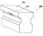
図8は、従来のタービン発電機ロータ300の一部の断面を模式的に示した図であり、図9は、図8に示したタービン発電機ロータ300の軸方向に対して垂直な面を一部断面として模式的に示した図である。図10は、図9のスロット303とウエッジ305の組立状態を模式的に示す斜視図である。図11は、変形したロータシャフト301を示す平面図である。図12は、ロータダブテール部にき裂を有するタービン発電機ロータ300を示す斜視図である。図13および図14は、ロータダブテール部に発生したき裂を除去する従来の方法を説明するためのタービン発電機ロータ300の斜視図である。
FIG. 8 is a diagram schematically showing a cross section of a part of a conventional
図8〜図10に示すように、タービン発電機ロータ300は、ロータシャフト301と一体に形成されたロータ鉄心部302とを備え、このロータ鉄心部302には、軸方向にスロット303が多数設けられている。これらのスロット303内の下部には、コイル304を挿入され、このコイル304上に絶縁ブロック306を介して複数個のウエッジ305が配設されている。これらのウエッジ305は、スロット303内の上部の挿入溝に挿入されて配設され、コイル304がロータシャフト301の回転による遠心力によってスロット303内から脱出するのを防止している。
As shown in FIGS. 8 to 10, the
ウエッジ305は、種々の形状に形成されるが、一般には、図10に示すようなダブテール形に形成され、その他にT字形、クリスマスツリー形などの形状に形成されることもある。これらのウエッジ305は、スロット303内に複数個挿入されているので、ウエッジ305とスロット303との接触面307には、互いに隣り合うウエッジ305の端面どうしが接する接触端部308が形成される。この接触端部308には、遠心力による面圧が集中するばかりでなく、図11に示すように、ロータ鉄心部302が自重または曲げ振動により曲率rで曲って、回転しているときにスロット303(ロータ鉄心部302)とウエッジ305との間に相対すべり±δが発生する。このため、接触端部308のロータ鉄心部302側にすべり方向に大きな引張、圧縮応力が集中するため、この部分にフレッティング損傷を生じ、疲労によるき裂が発生することがあった。
The
図11に示すように、ロータ鉄心部302の半径をro、ウエッジ305の長さをLとすると、ロータ鉄心部302は、上点Aおよび下点Bに至るとき、ウエッジ端部に相当する位置で、下記式(1)に示すδだけ伸縮するが、ウエッジ305は長手方向に分断されているので伸縮しない。したがって、ロータシャフト301の一回転毎にウエッジ305とロータ鉄心部302との接触端部308で相対すべり2δを発生する。
δ=ro・L/2r …式(1)
As shown in FIG. 11, when the radius of the
δ = ro · L / 2r (1)
上記したように、接触端部308では面圧が集中し、一般に面圧の高い接触面が相対すべりを伴うと、フレッティング損傷によりロータ鉄心部302側の接触面307に、図12に示すようなき裂309が発生することがあった。
As described above, the contact pressure is concentrated at the
また、このロータ鉄心部302側の接触面307に発生したき裂309は、ロータ鉄心部302が自重または曲げ振動により曲率rで曲がり回転しているときに生じる曲げ応力、タービン発電機の運転時のロータ鉄心部302の外径側と内径側の温度差による熱応力、材料の残留応力等により進展する可能性がある。そのため、例えば、ロータ鉄心部302側の接触面307に発生したき裂309を定期点検時などに除去をする技術が開示されている(例えば、特許文献1参照。)。
Further, the
この従来のき裂除去方法は、図13および図14に示すように、ロータ鉄心部302の接触面307に発生したき裂の周囲を、そのき裂の発生状態および大きさ等により切り欠いてき裂を除去し、き裂除去部310を形成している。
In this conventional crack removing method, as shown in FIGS. 13 and 14, the periphery of the crack generated on the
また、接触端部308のロータ鉄心部302側に応力集中緩和用の溝を設け、ウエッジ305とロータ鉄心部302との相対すべりによる接触端部のすべり方向の引張および圧縮応力の集中を緩和する技術が開示されている(例えば、特許文献2参照。)。さらに、ロータ鉄心部302側の接触面307のフレッティング疲労を軽減および防止する技術も開示されている(例えば、特許文献3−5参照。)。
上記したロータ鉄心部302側の接触面307に発生したき裂309を除去する従来の技術は、スロット303内側の狭隘部の加工作業となり、作業性が悪いという欠点があった。また、従来のウエッジ305とロータ鉄心部302との相対すべりによる接触端部のすべり方向の引張および圧縮応力の集中を緩和する技術や、ロータ鉄心部302側の接触面307のフレッティング疲労を軽減および防止する技術は、フレッティング疲労によるき裂の発生を防止する技術であり、発生したき裂を除去したり、き裂の進展を防止する技術ではなかった。
The conventional technique for removing the
そこで、本発明は、上記課題を解決するためになされたものであり、ロータ鉄心部の外周面からの処理により、ロータ鉄心部側のウエッジと接触面に発生したき裂を容易に除去することができる回転電機ロータのき裂除去方法、この回転電機ロータのき裂除去方法によってき裂が除去された回転電機ロータ、この回転電機ロータを備える回転電機を提供することを目的とする。 Accordingly, the present invention has been made to solve the above-described problems, and easily removes cracks generated on the wedge and the contact surface on the rotor core portion side by processing from the outer peripheral surface of the rotor core portion. It is an object of the present invention to provide a method for removing a crack in a rotating electrical machine rotor that can be used, a rotating electrical machine rotor from which a crack has been removed by the method for removing a crack in the rotating electrical machine, and a rotating electrical machine including the rotating electrical machine rotor.
上記目的を達成するために、本発明の回転電機ロータのき裂除去方法は、ロータ鉄心部の外周面に軸方向に形成された複数のスロットと、前記スロット内に収納されたコイルと、前記スロットの上部に軸方向に配列して挿入され、前記コイルを前記スロット内に保持するウエッジとを備える回転電機ロータにおける、前記スロットと前記ウエッジとの接触面に発生した前記ロータ鉄心部のき裂を除去するき裂除去方法であって、き裂が発生した前記ロータ鉄心部に隣接する一方のスロットから他方のスロットに貫通するように、前記ロータ鉄心部の外周面から前記き裂を含む前記ロータ鉄心部の中心軸側の領域を取り除き、前記き裂を除去することを特徴とする。 In order to achieve the above object, a method for removing a crack in a rotating electrical machine rotor according to the present invention includes a plurality of slots formed in an axial direction on an outer peripheral surface of a rotor iron core, a coil housed in the slot, Cracks in the rotor core portion generated on a contact surface between the slot and the wedge in a rotating electrical machine rotor including a wedge that is inserted in an axial direction at an upper portion of the slot and holds the coil in the slot A crack removing method for removing a crack from the outer peripheral surface of the rotor core portion so as to penetrate from one slot adjacent to the rotor core portion where the crack has occurred to the other slot. remove the realm of the central axis side of the rotor core portion, and removing the crack.
この回転電機ロータのき裂除去方法によれば、ロータ鉄心部の外周面からき裂の除去処理が可能であるので、容易にロータ鉄心部のき裂を除去することができ、さらに作業性にも優れている。 According to this method of removing a crack in a rotor of a rotor, since it is possible to remove the crack from the outer peripheral surface of the rotor core, it is possible to easily remove the crack in the rotor core, and to improve workability. Are better.
また、上記した回転電機ロータのき裂除去方法によってロータ鉄心部のき裂が除去された回転電機ロータや、この回転電機ロータを備える回転電機を構成することもできる。 Moreover, the rotary electric machine rotor from which the crack of the rotor core part was removed by the above-described crack removal method of the rotary electric machine rotor, and the rotary electric machine provided with this rotary electric machine rotor can also be configured.
本発明の回転電機ロータのき裂除去方法、回転電機ロータおよび回転電機によれば、ロータ鉄心部の外周面からの処理により、ロータ鉄心部側のウエッジと接触面に発生したき裂を容易に除去することができる。 According to the method for removing a crack in a rotating electrical machine rotor, the rotating electrical machine rotor, and the rotating electrical machine according to the present invention, a crack generated on the wedge and the contact surface on the rotor core part side can be easily performed by processing from the outer peripheral surface of the rotor core part. Can be removed.
以下、本発明の一実施の形態について図面を参照して説明する。 Hereinafter, an embodiment of the present invention will be described with reference to the drawings.
(第1の実施の形態)
本発明の第1の実施の形態について図1〜図3を参照して説明する。
(First embodiment)
A first embodiment of the present invention will be described with reference to FIGS.
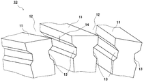
図1は、き裂14が発生した状態のロータ鉄心部11を有する回転電機ロータ10を模式的に示した斜視図である。図2は、き裂14を除去した状態のロータ鉄心部11を模式的に示した斜視図である。図3は、図2に示すロータ鉄心部11の側部を模式的に示した平面図である。
FIG. 1 is a perspective view schematically showing a rotating
図1に示すように、回転電機ロータ10のロータ鉄心部11の外周面には、中心軸方向に凹設され、軸方向に延設された複数のスロット12が形成されている。図示しないが、背景技術で述べたように、このスロット12内には、コイルが収納され、このコイルの半径方向外側には絶縁層を介してウエッジが挿入される。このウエッジは、回転電機ロータ10の回転によって発生する遠心力でコイルが半径方向に飛び出すのを押さえるもので、例えば、ダブテール形、T字形、クリスマスツリー形などの形状のものが用いられる。
As shown in FIG. 1, a plurality of
また、ウエッジは、スロット12の挿入溝13内に複数個挿入されているので、ウエッジとスロット12との接触面には、互いに隣り合うウエッジの端面どうしが接する接触端部が形成される。図1に示すように、この接触端部には、背景技術で述べたように、遠心力による面圧が集中するばかりでなく、ロータ鉄心部11が自重または曲げ振動により曲って、回転しているときにスロット12(ロータ鉄心部11)とウエッジとの間に相対すべりが発生し、ロータ鉄心部11側にフレッティング損傷を生じ、疲労によるき裂14が発生することがある。
Further, since a plurality of wedges are inserted into the
次に、このき裂14を除去する方法について、図2および図3を参照して説明する。
Next, a method for removing the
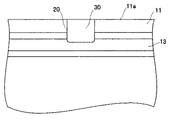
図2および図3に示すように、き裂14が形成されたロータ鉄心部11の外周面11aからき裂14を含むロータ鉄心部11の中心軸側の領域、およびこの領域に対応するロータ鉄心部11の円周方向に亘る領域を除去し、ロータ鉄心部11の外周面に切欠溝部20を形成する。この切欠溝部20を形成することによって、ロータ鉄心部11に形成されたき裂14を除去することができる。この切欠溝部20は、例えば、ボール盤などの工作機械を用いて形成される。
As shown in FIGS. 2 and 3, a region on the central axis side of the
切欠溝部20の軸方向の長さ(L)は、3mm〜20mmとすることが好ましい。また、切欠溝部20の深さは、ロータ鉄心部11に形成されたき裂14に対応して設定され、き裂14を完全に除去できる深さに設定される。また、切欠溝部20は、ロータ鉄心部11の円周方向に貫通し、開口した状態となっている。
The axial length (L) of the
ここで、切欠溝部20の底面20aは、ロータ鉄心部11が自重または曲げ振動により所定の曲率で曲って回転している時に生じる曲げ応力、ロータ鉄心部11の外径側と内径側の温度差による熱応力、材料の残留応力等の軸方向応力による高サイクル疲労、および起動停止時のスロット12内遠心力の変動による低サイクル疲労を受ける応力環境下にある。また、ロータ鉄心部11のスロット12の上部は、回転電機ロータ10の起動停止時のスロット12内における遠心力の変動による低サイクル疲労を受ける応力環境下にある。
Here, the
上記したように、切欠溝部20の軸方向の長さ(L)を3mm以上に設定することが好ましいのは、切欠溝部20の軸方向の長さ(L)が3mmよりも短い場合には、切欠溝部20の底面20aの応力集中係数が大きくなり、上記した疲労強度が低下するからである。また、切欠溝部20の軸方向の長さ(L)を20mm以下に設定することが好ましいのは、切欠溝部20の軸方向の長さ(L)が20mmより長くなると、切欠溝部20近傍のロータ鉄心部11とウエッジとの接触面圧が大きくなり、さらに、切欠溝部20において応力集中によりロータ鉄心部11およびウエッジの応力が大きくなり、上記した疲労強度が低下するからである。
As described above, the axial length (L) of the
また、図3に示すように、切欠溝部20の底面20aと、切欠溝部20の側面20bとの交わる部分を、鋭角に相互の面が交わるように構成してもよいが、曲率を持ったR部20cとして構成することが好ましい。このように、底面20aと側面20bとが交わる部分をR部20cとすることで、切欠溝部を加工したことによる応力集中を緩和し疲労強度の低下を防止することができる。また、このR部20cは、1.5mm以上の曲率半径を有していることが好ましい。ここで、R部20cの曲率半径を1.5mm以上とすることが好ましいのは、R部20cの曲率半径が1.5mmより小さい場合には、応力集中により切欠溝底部応力が高くなり疲労強度が低下するからである。
Further, as shown in FIG. 3, a portion where the
上記したように、第1の実施の形態におけるロータ鉄心部11に形成されたき裂14を除去する方法によれば、ロータ鉄心部11の外周面からき裂14の除去処理が可能であるので、容易にロータ鉄心部11のき裂14を除去することができ、さらに作業性にも優れている。また、き裂14を完全に除去することができるので、き裂除去後におけるロータ鉄心部11の信頼性を確保することができる。また、切欠溝部20の軸方向の長さ(L)が長い場合には、ロータ鉄心部11におけるき裂14の中心軸方向への進展の状態を非破壊検査により容易に確認することができる。
As described above, according to the method for removing the
なお、ロータ鉄心部11に設置されている振動調整用のバランスプラグによりバランスを調整することにより、ロータ鉄心部11の一部を除去して切欠溝部20を形成しても、最適な重量バランスを維持することが可能となる。
Even if the
(第2の実施の形態)
本発明の第2の実施の形態について図4を参照して説明する。
(Second Embodiment)
A second embodiment of the present invention will be described with reference to FIG.
第2の実施の形態におけるロータ鉄心部11に形成されたき裂14を除去する方法では、切欠溝部20の軸方向の長さ(L)を1mm〜20mmに設定する一例について説明する。なお、切欠溝部20の軸方向の長さ(L)が3mm〜20mmの場合については、第1の実施の形態におけるロータ鉄心部11に形成されたき裂14を除去する方法で説明したので、ここでは、切欠溝部20の軸方向の長さ(L)を1mm以上3mm未満とする場合について説明する。
In the method for removing the
図4は、き裂14を除去した状態のロータ鉄心部11の側部を模式的に示した平面図である。なお、第1の実施の形態における構成と同一部分には同一符号を付して、重複する説明を簡略または省略する。
FIG. 4 is a plan view schematically showing a side portion of the
図4に示すように、切欠溝部20の軸方向の長さ(L)を1mm以上3mm未満とする場合、切欠溝部20の底面20aと、切欠溝部20の軸方向の側面20bとが交わる部分を曲率半径が1.5mm以上の曲面となるように加工処理を施す。この場合、切欠溝部20の軸方向の長さ(L)が3mm未満であるため、底面20aの形状は円形状となり、切欠溝部20は全体として鍵穴状の形状を有している。
As shown in FIG. 4, when the axial length (L) of the
ここで、切欠溝部20の軸方向の長さ(L)を1mm以上3mm未満とする場合に、切欠溝部20の底面20aと、切欠溝部20の軸方向の側面20bとが交わる部分の曲面の曲率半径を1.5mm以上とするのは、曲率半径(r)が1.5mmよりも小さいときには、応力集中により切欠溝底部応力が高くなり疲労強度が低下するからである。
Here, when the axial length (L) of the
上記したように、第2の実施の形態におけるロータ鉄心部11に形成されたき裂14を除去する方法によれば、ロータ鉄心部11の外周面からき裂14の除去処理が可能であるので、容易にロータ鉄心部11のき裂14を除去することができ、さらに作業性にも優れている。
As described above, according to the method for removing the
また、ロータ鉄心部11に形成されたき裂14が小さい場合に、切欠溝部20の底面20aと、切欠溝部20の軸方向の側面20bとが交わる部分を曲率半径が1.5mm以上の曲面となるように加工処理を施すことで、切欠溝部20の軸方向の長さ(L)が1mm以上3mm未満の範囲でも、切欠溝部20の底面20aの応力集中係数の増加を抑え、疲労強度の低下を抑制することができる。
When the
なお、第2の実施の形態の場合と同様に、ロータ鉄心部11に設置されている振動調整用のバランスプラグによりバランスを調整することにより、ロータ鉄心部11の一部を除去して切欠溝部20を形成しても、最適な重量バランスを維持することが可能となる。
Similarly to the case of the second embodiment, the balance is adjusted by a vibration adjusting balance plug installed in the
(第3の実施の形態)
本発明の第3の実施の形態について図5〜図7を参照して説明する。
(Third embodiment)
A third embodiment of the present invention will be described with reference to FIGS.
第3の実施の形態では、第1および第2の実施の形態における切欠溝部20に充填部材を装着した構成について説明する。
In the third embodiment, a configuration in which a filling member is attached to the
図5は、第1の実施の形態における切欠溝部20に充填部材30を充填した状態のロータ鉄心部11の側部を模式的に示した平面図である。図6は、第2の実施の形態における切欠溝部20に充填部材40を充填した状態のロータ鉄心部11の側部を模式的に示した平面図である。図7は、他の形状を有する切欠溝部20に充填部材50を充填した状態のロータ鉄心部11の側部を模式的に示した平面図である。
FIG. 5 is a plan view schematically showing the side portion of the
図5および図6に示すように、切欠溝部20には、切欠溝部20の形状とほぼ同じ形状を有する充填部材30、40が挿入され、ロータ鉄心部11に接合されている。図5に示すように、切欠溝部20の軸方向の長さ(L)を維持したままロータ鉄心部11の中心軸側に切欠溝部20が形成される場合には、充填部材30を切欠溝部20の上方(ロータ鉄心部11の外周面側)から切欠溝部20内に挿入することができる。一方、図6に示すように、切欠溝部20の軸方向の長さ(L)が維持されずに、ロータ鉄心部11の中心軸側に切欠溝部20の軸方向の長さ増加する切欠溝部20が形成される場合には、充填部材40を切欠溝部20の側方(スロット12側)から切欠溝部20内に挿入することができる。
As shown in FIGS. 5 and 6, filling
また、切欠溝部20に挿入された充填部材30、40は、ロータ鉄心部11と、例えば溶接により接合される。また、充填部材30、40とロータ鉄心部11との接合方法は、溶接に限られるものではなく、充填部材30、40をロータ鉄心部11にネジなどによって螺設してもよく、すなわち切欠溝部20内に充填部材30、40を保持できる接合方法であればよい。
Further, the filling
充填部材30、40は、各ロータ鉄心部11との重量バランスを均一にするために、ロータ鉄心部11を形成する材料と同一の材料、またはロータ鉄心部11を形成する材料とほぼ比重が同じ材料で構成されることが好ましい。また、充填部材30、40は、ロータ鉄心部11を形成する材料よりも軟質な材料で形成されてもよい。この軟質な材料として、例えば、アルミ合金などが挙げられるが、これに限られるものではない。充填部材30、40をロータ鉄心部11を形成する材料よりも軟質な材料で形成することで、充填部材30、40とロータ鉄心部11との接触面におけるフレッティング損傷を防止することができる。
In order to make the weight balance with each
また、切欠溝部20の軸方向の長さ(L)が3mm〜20mmの場合、図7に示すように、切欠溝部20の軸方向の側面20bに円周方向に凹条溝部20dを形成し、この切欠溝部20の形状とほぼ同じ形状を有する充填部材50を挿入し、充填部材50の凸部50aを凹条溝部20dに係合して、ロータ鉄心部11に装着してもよい。この場合、充填部材50の凸部50aが凹条溝部20dに係合するので、溶接などの接合処理を施さなくとも、充填部材50を切欠溝部20内に保持することができる。
Further, when the axial length (L) of the
上記したように、切欠溝部20に充填部材を装着することで、各ロータ鉄心部11との重量バランスを均一にすることができる。また、ロータ鉄心部11の外周面に流れる電流、ロータ鉄心部11の外周面における通風抵抗などを、他のロータ鉄心部11と同様にすることができる。
As described above, by attaching the filling member to the
以上、本発明を第1〜第3の実施の形態により具体的に説明したが、本発明はこれらの実施の形態にのみ限定されるものではなく、その要旨を逸脱しない範囲で種々変更可能である。また、本発明は、電動機や発電機などの回転電機全般に適用することができる。 The present invention has been specifically described with reference to the first to third embodiments. However, the present invention is not limited to these embodiments, and various modifications can be made without departing from the scope of the present invention. is there. Further, the present invention can be applied to general rotating electrical machines such as electric motors and generators.
10…回転電機ロータ、11…ロータ鉄心部、11a…外周面、12…スロット、13…挿入溝、14…き裂、20…切欠溝部、20a…底面、20b…側面、20c…R部。
DESCRIPTION OF
Claims (12)
き裂が発生した前記ロータ鉄心部に隣接する一方のスロットから他方のスロットに貫通するように、前記ロータ鉄心部の外周面から前記き裂を含む前記ロータ鉄心部の中心軸側の領域を取り除き、前記き裂を除去することを特徴とする回転電機ロータのき裂除去方法。 A plurality of slots formed in the axial direction on the outer peripheral surface of the rotor core portion, a coil accommodated in the slot, and an axial arrangement arranged above the slot, and holding the coil in the slot In a rotating electrical machine rotor comprising a wedge, a crack removing method for removing a crack in the rotor core portion generated on a contact surface between the slot and the wedge,
From one of the slots adjacent to the rotor core section crack occurs so as to penetrate into the other slot, the realm of the central axis side of the rotor core portion including the crack from the outer peripheral surface of the rotor core portion A method for removing a crack in a rotating electric machine rotor, comprising removing the crack.
Priority Applications (3)
| Application Number | Priority Date | Filing Date | Title |
|---|---|---|---|
| JP2005380344A JP4834401B2 (en) | 2005-12-28 | 2005-12-28 | Method for removing cracks in rotating electrical machine rotor, rotating electrical machine rotor and rotating electrical machine |
| AU2006252256A AU2006252256B2 (en) | 2005-12-28 | 2006-12-22 | Method for removing a crack in an electromechanical rotor, electromechanical rotor and rotary electrical machine |
| US11/645,507 US8333006B2 (en) | 2005-12-28 | 2006-12-27 | Method for removing a crack in an electromechanical rotor |
Applications Claiming Priority (1)
| Application Number | Priority Date | Filing Date | Title |
|---|---|---|---|
| JP2005380344A JP4834401B2 (en) | 2005-12-28 | 2005-12-28 | Method for removing cracks in rotating electrical machine rotor, rotating electrical machine rotor and rotating electrical machine |
Publications (2)
| Publication Number | Publication Date |
|---|---|
| JP2007181380A JP2007181380A (en) | 2007-07-12 |
| JP4834401B2 true JP4834401B2 (en) | 2011-12-14 |
Family
ID=38265029
Family Applications (1)
| Application Number | Title | Priority Date | Filing Date |
|---|---|---|---|
| JP2005380344A Active JP4834401B2 (en) | 2005-12-28 | 2005-12-28 | Method for removing cracks in rotating electrical machine rotor, rotating electrical machine rotor and rotating electrical machine |
Country Status (3)
| Country | Link |
|---|---|
| US (1) | US8333006B2 (en) |
| JP (1) | JP4834401B2 (en) |
| AU (1) | AU2006252256B2 (en) |
Families Citing this family (5)
| Publication number | Priority date | Publication date | Assignee | Title |
|---|---|---|---|---|
| FR2935205B1 (en) | 2008-08-20 | 2010-10-08 | Michelin Soc Tech | INTERIOR ROTOR FOR ROTATING ELECTRIC MACHINE AND METHOD FOR ASSEMBLING THE SAME |
| FR2935206B1 (en) * | 2008-08-20 | 2010-10-08 | Michelin Soc Tech | INTERIOR ROTOR FOR ELECTRICAL MACHINE WITH "T" -shaped MAGNETS |
| EP2642645A1 (en) * | 2012-03-20 | 2013-09-25 | Alstom Technology Ltd. | Method for repairing a stator |
| CN103926855B (en) * | 2014-05-04 | 2016-06-08 | 天津理工大学 | One delays rotor crack extended method by electromagnetic actuator |
| US10103608B2 (en) * | 2015-04-17 | 2018-10-16 | General Electric Company | Generator rotor fretting fatigue crack repair method |
Family Cites Families (12)
| Publication number | Priority date | Publication date | Assignee | Title |
|---|---|---|---|---|
| US2252986A (en) * | 1939-03-03 | 1941-08-19 | Lawrence B Scott | Method of repairing cracked or fractured metal walls |
| JPS59213249A (en) * | 1983-05-18 | 1984-12-03 | Hitachi Ltd | Rotor for turbine generator |
| JPS6192138A (en) * | 1984-10-09 | 1986-05-10 | Hitachi Ltd | Seam position altering method of rotor wedge in rotary electric machine |
| JPS61197485A (en) * | 1985-02-26 | 1986-09-01 | 住友電気工業株式会社 | Surface lubrication for ceramic substrate of thin film circuit |
| JPH03243261A (en) * | 1990-02-19 | 1991-10-30 | Kawasaki Steel Corp | Method for executing grinding cleaning for melt-cutting face in continuously cast slab |
| JPH0744802B2 (en) * | 1990-05-18 | 1995-05-15 | 株式会社日立製作所 | Turbine generator rotor |
| JPH0429304A (en) | 1990-05-24 | 1992-01-31 | Seiko Epson Corp | Magnetic field generation device |
| JPH0574304A (en) | 1991-09-09 | 1993-03-26 | Secoh Giken Inc | Changeover switch operated by input pulse current |
| JP3347191B2 (en) | 1993-07-30 | 2002-11-20 | 日本電設工業株式会社 | Trolley wire cutting device |
| JP3150013B2 (en) | 1993-08-03 | 2001-03-26 | 日本電気アイシーマイコンシステム株式会社 | Load open detection circuit |
| US5883456A (en) * | 1997-10-20 | 1999-03-16 | Siemens Westinghouse Power Corporation | Generator rotor and method for eliminating keyway stress cracks in same |
| US6849972B1 (en) * | 2003-08-27 | 2005-02-01 | General Electric Company | Generator rotor fretting fatigue crack repair |
-
2005
- 2005-12-28 JP JP2005380344A patent/JP4834401B2/en active Active
-
2006
- 2006-12-22 AU AU2006252256A patent/AU2006252256B2/en active Active
- 2006-12-27 US US11/645,507 patent/US8333006B2/en active Active
Also Published As
| Publication number | Publication date |
|---|---|
| US20070169334A1 (en) | 2007-07-26 |
| AU2006252256B2 (en) | 2009-02-05 |
| JP2007181380A (en) | 2007-07-12 |
| AU2006252256A1 (en) | 2007-07-12 |
| US8333006B2 (en) | 2012-12-18 |
Similar Documents
| Publication | Publication Date | Title |
|---|---|---|
| JP4834401B2 (en) | Method for removing cracks in rotating electrical machine rotor, rotating electrical machine rotor and rotating electrical machine | |
| EP2124319B1 (en) | Electric rotating machine | |
| US20120112600A1 (en) | Stator for electric rotating machine | |
| JP4834402B2 (en) | Crack repair method for rotating electrical machine rotor, crack propagation preventing method for rotating electrical machine rotor, rotating electrical machine rotor, and rotating electrical machine | |
| US20180278106A1 (en) | Rotor for induction motor and induction motor | |
| US20160094098A1 (en) | Rotor and rotating electric machine | |
| JP4834462B2 (en) | Method for removing crack in rotating electric machine rotor, method for preventing crack propagation in rotating electric machine rotor, rotating electric machine rotor and rotating electric machine | |
| EP2787607A2 (en) | Electric machine rotor | |
| JP5386885B2 (en) | Rotor structure of permanent magnet rotating machine | |
| JP5931216B2 (en) | Rotor for rotating electrical machine and method for manufacturing the same | |
| EP3785354B1 (en) | False tooth assembly for generator stator core | |
| JP6738395B2 (en) | Rotor | |
| JP2016152652A (en) | Winding device for flat wire | |
| JP5638096B2 (en) | Permanent magnet synchronous motor rotor, motor and machine tool | |
| JP7080278B2 (en) | Rotor, rotor manufacturing method and rotary electric machine | |
| JP6329981B2 (en) | Stator core fixing structure and manufacturing method of stator core fixing structure | |
| WO2000016466A1 (en) | Rotating electric machine | |
| JP6740320B2 (en) | Rotor, motor and method of manufacturing rotor | |
| JP7382293B2 (en) | Blocky rotor, rotating electric machine, and rotor slot forming method | |
| EP3082234B1 (en) | Turbo-generator rotor fretting fatigue crack repair method | |
| EP0999637B1 (en) | Rotor for an electric machine, retainer for retaining a winding in a slot in a rotor, and method of manufacturing a rotor | |
| JP7387035B2 (en) | Rotor of rotating electrical machine and rotating electrical machine | |
| JP2009219277A (en) | Coil wedge of turbine generator, turbine generator, and method of repairing coil wedge of turbine generator | |
| JP2016152707A (en) | Dynamo-electric machine | |
| WO2014068356A1 (en) | Grooved wedge for rotor |
Legal Events
| Date | Code | Title | Description |
|---|---|---|---|
| A621 | Written request for application examination |
Free format text: JAPANESE INTERMEDIATE CODE: A621 Effective date: 20080319 |
|
| A131 | Notification of reasons for refusal |
Free format text: JAPANESE INTERMEDIATE CODE: A131 Effective date: 20110201 |
|
| A977 | Report on retrieval |
Free format text: JAPANESE INTERMEDIATE CODE: A971007 Effective date: 20110203 |
|
| RD02 | Notification of acceptance of power of attorney |
Free format text: JAPANESE INTERMEDIATE CODE: A7422 Effective date: 20110323 |
|
| A521 | Request for written amendment filed |
Free format text: JAPANESE INTERMEDIATE CODE: A523 Effective date: 20110324 |
|
| A521 | Request for written amendment filed |
Free format text: JAPANESE INTERMEDIATE CODE: A821 Effective date: 20110323 |
|
| TRDD | Decision of grant or rejection written | ||
| A01 | Written decision to grant a patent or to grant a registration (utility model) |
Free format text: JAPANESE INTERMEDIATE CODE: A01 Effective date: 20110830 |
|
| A01 | Written decision to grant a patent or to grant a registration (utility model) |
Free format text: JAPANESE INTERMEDIATE CODE: A01 |
|
| A61 | First payment of annual fees (during grant procedure) |
Free format text: JAPANESE INTERMEDIATE CODE: A61 Effective date: 20110926 |
|
| R151 | Written notification of patent or utility model registration |
Ref document number: 4834401 Country of ref document: JP Free format text: JAPANESE INTERMEDIATE CODE: R151 |
|
| FPAY | Renewal fee payment (event date is renewal date of database) |
Free format text: PAYMENT UNTIL: 20140930 Year of fee payment: 3 |