JP4831477B2 - Instrument device and driving method thereof - Google Patents
Instrument device and driving method thereof Download PDFInfo
- Publication number
- JP4831477B2 JP4831477B2 JP2006145200A JP2006145200A JP4831477B2 JP 4831477 B2 JP4831477 B2 JP 4831477B2 JP 2006145200 A JP2006145200 A JP 2006145200A JP 2006145200 A JP2006145200 A JP 2006145200A JP 4831477 B2 JP4831477 B2 JP 4831477B2
- Authority
- JP
- Japan
- Prior art keywords
- value
- pointer
- instrument device
- output
- drive
- Prior art date
- Legal status (The legal status is an assumption and is not a legal conclusion. Google has not performed a legal analysis and makes no representation as to the accuracy of the status listed.)
- Active
Links
- 238000000034 method Methods 0.000 title claims description 25
- 238000013459 approach Methods 0.000 claims description 7
- 238000001514 detection method Methods 0.000 description 13
- 238000005286 illumination Methods 0.000 description 6
- 230000007704 transition Effects 0.000 description 4
- 230000003111 delayed effect Effects 0.000 description 2
- 238000005259 measurement Methods 0.000 description 2
- 238000012545 processing Methods 0.000 description 2
- 230000007423 decrease Effects 0.000 description 1
- 238000013461 design Methods 0.000 description 1
- 239000000463 material Substances 0.000 description 1
- 238000003672 processing method Methods 0.000 description 1
- 239000011347 resin Substances 0.000 description 1
- 229920005989 resin Polymers 0.000 description 1
- 239000004065 semiconductor Substances 0.000 description 1
- XLYOFNOQVPJJNP-UHFFFAOYSA-N water Substances O XLYOFNOQVPJJNP-UHFFFAOYSA-N 0.000 description 1
Images


Landscapes
- Instrument Panels (AREA)
Description
本発明は、指針が装着される駆動本体に目標値と現在値とに基づいて算出される出力値を所定周期で出力し、前記駆動本体の駆動に応じて前記指針を表示板上で回動させて情報を表示する計器装置及びその駆動方法に関するものである。 According to the present invention, an output value calculated based on a target value and a current value is output to a drive main body to which a pointer is attached at a predetermined cycle, and the pointer is rotated on a display board according to the drive of the drive main body. The present invention relates to an instrument device for displaying information and a driving method thereof.
車速,エンジン回転数,水温,油圧等の様々な車両の状態に関する情報(以下、車両情報という)を表示する計器装置としては、例えばステッピングモータからなる駆動本体に指針が装着され、前記駆動本体の駆動に応じて前記指針を表示板上で回動させることで前記車両情報を表示する指針表示式計器が知られている。 As an instrument device for displaying various vehicle status information (hereinafter referred to as vehicle information) such as vehicle speed, engine speed, water temperature, hydraulic pressure, etc., a pointer is attached to a drive main body composed of a stepping motor, for example. There is known a pointer display type instrument that displays the vehicle information by rotating the pointer on a display board according to driving.
かかる計器装置においては、前記駆動本体たるステッピングモータは、マイコン等からなる制御手段より目標値と現在値とに基づいて算出される出力値を所定周期で入力し、指針を回動させるべく駆動するものである。しかしながら前記出力値が前記目標値に達するまでステッピングモータを同一速度で駆動させるとステッピングモータのトルクが小さい場合には脱調が生じるおそれがあるため、前記出力値が前記目標値に近づくのに応じて前記出力値の変化量を減少させ、駆動速度を遅らせる遅延処理を行うのが一般的である。なお、指針表示式計器の遅延処理については例えば特許文献1に開示されている。
In such an instrument device, the stepping motor, which is the drive main body, inputs an output value calculated based on the target value and the current value from a control means such as a microcomputer at a predetermined period, and drives to rotate the pointer. Is. However, if the stepping motor is driven at the same speed until the output value reaches the target value, a step-out may occur when the torque of the stepping motor is small, so that the output value approaches the target value. In general, a delay process for reducing the amount of change in the output value and delaying the driving speed is performed. Note that the delay process of the pointer display type instrument is disclosed in, for example,
また、計器装置に関しては斬新なデザインが望まれており、所定の開始信号に応じて前記車両情報の表示とは異なる動作(非表示動作)を行うものが知られている。かかる非表示動作としては、車両の電源スイッチのオンなる入力に応じて初期動作を行うものや前記電源スイッチのオフなる入力に応じて終了動作を行うものが知られている。この初期動作あるいは終了動作としては、指針表示式計器に関しては指針を所定の範囲内(例えば零点位置から最高目盛り位置まで)で回動させるものがある。このような初期動作あるいは終了動作については例えば特許文献2に開示されている。
しかしながら、従来の計器装置では、前記非表示動作においても通常の表示動作と同様に前記遅延処理を行う結果、前記非表示動作に過剰な時間を要することで計器装置が通常の表示動作に復帰するのが遅れ、使用者に煩わしさを感じさせる場合があるといった問題点を有している。 However, in the conventional instrument device, as a result of performing the delay process in the non-display operation similarly to the normal display operation, the instrument device returns to the normal display operation because the non-display operation takes excessive time. However, there is a problem that the user may feel troublesome.
そこで、本発明は、上述した課題に着目してなされたものであり、所定の開始信号入力に応じて指針を所定範囲内で回動動作させる際に、回動動作時間を短縮させ見栄えの良い動作が可能な計器装置及びその駆動方法を提供することを目的とするものである。 Therefore, the present invention has been made paying attention to the above-described problems, and when the pointer is rotated within a predetermined range in response to a predetermined start signal input, the rotation operation time is shortened and good-looking. It is an object of the present invention to provide an instrument device that can operate and a driving method thereof.
本発明の計器装置は、前記課題を解決するため、指針が装着される駆動本体に目標値と現在値とに基づいて算出される出力値を所定周期で出力する制御手段を有し、前記駆動本体の駆動に応じて前記指針を表示板上で回動させて情報を指示表示する計器装置であって、前記制御手段は、前記出力値が前記目標値に近づくのに応じて徐々にその変化量を小さくする遅延処理を実行し、また、所定の開始信号入力に応じて前記指針に所定範囲で回動動作をさせる際に、前記現在値が前記目標値よりも小さい値で設定される判定値に達したか否かを判定し、前記現在値が前記判定値に達したと判定される場合は前記回動動作を終了させてなることを特徴とする。 In order to solve the above problems, the instrument device of the present invention has a control means for outputting an output value calculated based on a target value and a current value at a predetermined period to a drive body to which a pointer is attached, and the drive An instrument device for rotating and displaying the pointer on a display board in accordance with driving of a main body to indicate and display information, wherein the control means gradually changes as the output value approaches the target value. Performing a delay process to reduce the amount, and determining that the current value is set to a value smaller than the target value when the pointer is rotated within a predetermined range in response to a predetermined start signal input It is determined whether or not a value has been reached, and when it is determined that the current value has reached the determination value, the rotation operation is terminated.
また、前記判定値は、前記出力値の変化量が前記指針の回動を視認できない程度となる値に設定されることを特徴とする。 Further, the determination value is set to a value at which the change amount of the output value is such that the rotation of the pointer cannot be visually recognized.
また、前記制御手段は、前記開始信号として電源スイッチのオンもしくはオフなる入力に基づいて前記回動動作をさせることを特徴とする。 Further, the control means causes the rotation operation based on an input to turn on or off a power switch as the start signal.
本発明の計器装置の駆動方法は、指針が装着される駆動本体に目標値と現在値とに基づいて算出される出力値を所定周期で出力し、前記駆動本体の駆動に応じて前記指針を表示板上で回動させて情報を表示する計器装置の駆動方法であって、前記出力値が前記目標値に近づくのに応じて徐々にその変化量を小さくする遅延処理を実行し、また、所定の開始信号入力に応じて前記指針に所定範囲で回動動作をさせる際に、前記現在値が前記目標値よりも小さい値で設定される判定値に達したか否かを判定し、前記現在値が前記判定値に達したと判定される場合は前記回動動作を終了させることを特徴とする。 The method for driving an instrument device according to the present invention outputs an output value calculated based on a target value and a current value to a drive main body to which a pointer is attached at a predetermined cycle, and the pointer is displayed according to the drive of the drive main body. A method of driving an instrument device that rotates and displays information on a display board, and executes a delay process that gradually reduces the amount of change as the output value approaches the target value. When turning the pointer within a predetermined range in response to a predetermined start signal input, it is determined whether or not the current value has reached a determination value set at a value smaller than the target value, The rotation operation is terminated when it is determined that the current value has reached the determination value.
また、前記判定値は、前記出力値の変化量が前記指針の回動を視認できない程度となる値に設定されることを特徴とする。 Further, the determination value is set to a value at which the change amount of the output value is such that the rotation of the pointer cannot be visually recognized.
また、前記開始信号として、電源スイッチのオンもしくはオフなる入力に基づいて前記回動動作をさせることを特徴とする。 Further, the rotation operation is performed based on an input for turning on or off a power switch as the start signal.
本発明は、指針が装着される駆動本体に目標値と現在値とに基づいて算出される出力値を所定周期で出力し、前記駆動本体の駆動に応じて前記指針を表示板上で回動させて情報を表示する計器装置及びその駆動方法に関するものであり、所定の開始信号入力に応じて指針に所定範囲で回動動作をさせる際に、回動動作時間を短縮させ見栄えの良い動作が可能となる。 According to the present invention, an output value calculated based on a target value and a current value is output to a drive main body to which a pointer is attached at a predetermined cycle, and the pointer is rotated on a display board according to the drive of the drive main body. The instrument device for displaying information and the driving method thereof, and when the pointer is rotated within a predetermined range in response to a predetermined start signal input, the rotation operation time is shortened and a good-looking operation is performed. It becomes possible.
以下、本発明を単一のケース体に指針式計器を収納した計器装置に適用した実施形態を添付図面に基づいて説明する。 Hereinafter, an embodiment in which the present invention is applied to an instrument device in which a pointer-type instrument is housed in a single case body will be described with reference to the accompanying drawings.
図1及び図2を用いて計器装置1の全体構成を説明する。計器装置1は、ケース体2と、計器本体3と、車両情報検出手段4と、IGN(イグニッション)検出手段5と、制御手段6とから主に構成されている。
The overall configuration of the
ケース体2は、例えば樹脂製材料から構成され、電気構成部品を含む計器本体3を収納する単一ケースである。尚、ケース体2の前面側は、図示しない暗色系のカバー体によって覆われる。
The
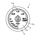
計器本体3は、ステッピングモータからなる駆動本体3aと、駆動本体3aを駆動させるための駆動回路3bと、計器本体3の照明用光源として設けられる複数の発光素子(LED)群からそれぞれ形成される第一,第二の照明手段3c,3dを備えている。また計器本体3は、駆動本体3aに回転軸(図示しない)を介して指針3eが装着されており、指針3eの背後に配設される表示板3fに形成される目盛りや数字等の表示指標3gと指針3eとの対比判読で車両情報の変化を知ることが可能となっている。なお、本実施形態では計器本体3は、前記車両情報としてエンジンの吸気圧を表示するものである。なお、指針3e及び表示板3fは、それぞれ第一,第二の照明手段3c,3dによって照明されるものであり、第一,第二の照明手段3c,3dから発せられる照明光によって、指針3eの指示部が光輝し、また表示指標3gが透過照明され、指針3e及び表示指標3gの表示像が前記カバー体の暗色系の背景に浮かび上がるように運転者に視認される。
The
車両情報検出手段4は、車両情報を検出するための各センサからなるもので、本実施形態では、車両エンジンの吸気圧を検出する半導体式圧力検出素子を備えた圧力センサからなる。 The vehicle information detection means 4 is composed of sensors for detecting vehicle information. In the present embodiment, the vehicle information detection means 4 is composed of a pressure sensor including a semiconductor pressure detection element for detecting intake pressure of the vehicle engine.
IGN検出手段5は、車両のIGNスイッチ7のオフ状態からオン状態への移行及びオン状態からオフ状態への移行を検出するもので、IGNスイッチ7のオン状態あるいはオフ状態を検出すると、制御手段6へそれぞれ検出信号を出力する。なお、IGNスイッチ7のオン状態とは、IGNスイッチ7のオフ状態からアクセサリー電源のオン状態への移行、IGNスイッチ7のオフ状態からエンジンスタートのオン状態への移行、あるいはアクセサリー電源のオン状態からエンジンスタートのオン状態への移行の何れの状態であっても良い。なお、IGNスイッチ7は、一端が車両のバッテリー電源8へ、他端がIGN検出手段5へ接続されている。
The IGN detection means 5 detects the transition of the IGN
制御手段6は、CPU,ROM,RAM及び入出力インターフェイス等を備えたマイクロコンピュータから構成される。制御手段6は、車両情報検出手段4から状態信号を入力し、前記状態信号に基づいて車両情報の計測データを所定の演算処理によって求め、前記計測データに応じた駆動信号を駆動回路3bを介して所定周期で駆動本体3aへ出力して駆動本体3aを駆動させ、駆動本体3aに装着された指針3eを回動動作させるものである。また、制御手段6は、IGN検出手段5からのIGNスイッチ7のオンなる検出信号を入力した際に、計器本体3に前記車両情報の表示動作とは異なる初期動作(非表示動作)をさせるための後で詳述する初期動作機能を有している。
The control means 6 is constituted by a microcomputer provided with a CPU, ROM, RAM, an input / output interface and the like. The control means 6 receives a state signal from the vehicle information detection means 4, obtains measurement data of vehicle information based on the state signal by a predetermined calculation process, and sends a drive signal corresponding to the measurement data via the drive circuit 3b. In this manner, the drive body 3a is driven at a predetermined cycle to drive the drive body 3a, and the pointer 3e attached to the drive body 3a is rotated. Further, when the control means 6 inputs a detection signal for turning on the IGN
以上の各部によって計器装置1が構成されている。次に、図3を用いて計器装置1における制御手段6の初期動作機能について説明する。なお、計器本体3は、指示角度が0°から270°であり、最小目盛位置が時計目盛位置の6時の位置となり、また最大目盛位置が時計目盛位置の3時の位置となるように表示板3fの表示指標3gが形成されるものが用いられる。
The
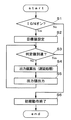
制御手段6は、IGN検出手段5を介してIGNスイッチ7のオン状態(オンなる入力)を検出する(ステップS1)と、前記初期動作として所定範囲内で指針3eを回動動作させるべく、表示板3fにおける指針3eの指示目標となる位置に対応する目標値Aを設定する(ステップS2)。なお、本実施形態においては目標値Aは指針3eが最大目盛位置を指示する値に設定される。
When the control means 6 detects the ON state (input to be turned on) of the IGN
次に、制御手段6は、指針3eの現在の指示位置を示す現在値Bが目標値Aよりも小さい近似値に設定される判定値Cに達しているか否かを判定する(ステップS3)。なお、現在値Bは指針3eの回動開始前は0であり、回動開始後は前回の出力値Xとなる。 Next, the control means 6 determines whether or not the current value B indicating the current indicated position of the pointer 3e has reached a determination value C set to an approximate value smaller than the target value A (step S3). The current value B is 0 before the rotation of the pointer 3e is started, and becomes the previous output value X after the rotation is started.
制御手段6は、ステップS3において現在値Bが判定値Cに達していない(B<C)と判定する場合、ステップS4に移行して駆動本体3aに出力する出力値Xを算出する。出力値Xは、表示板3fにおける次に指針3eを移動させるべき位置に対応する値であって、現在値Bに目標値A及び現在値Bに基づいて得られる変化量Yを加算して算出される(X=B+Y)。なお、変化量Yは(|A−B|+R)/Nの商により算出される(Rは前回の変化量Yの算出時の余りであり、Nは所定の遅延定数である)。かかる演算式を用いることによって、算出される出力値Xは図4に示すように回動開始時はその変化量Yが大きく、目標値Aに近づくのに応じて変化量Yが徐々に小さくなるため、駆動本体3aの動作を徐々に減速する遅延処理を施すことが可能となっている。次いで、制御手段6は、駆動本体3aに出力値Xを駆動信号として出力し、駆動本体3aを駆動させて前記初期動作として指針3eを表示板3fの表示指標3gにおける最大目盛り方向に向けて回動させる。なお、制御手段6は、前記初期動作に際して指針3eの回動開始と同時あるいはその前に第一,第二の照明手段3c,3dを点灯させる。また、制御手段6は、出力値Xを次回の現在値Bとして保持する。そして、制御手段6は、出力値Xの出力後にステップS3に移行して新たな現在値Bと判定値Cとの比較判定を再度実行する。
When it is determined in step S3 that the current value B has not reached the determination value C (B <C), the
制御手段6は、ステップS3において現在値Bが判定値Cに達している(B≧C)と判定する場合は、最大目盛方向への回動動作を終了させ、指針3eを原点位置(最小目盛位置)に復帰させるべく帰零信号を駆動本体3aに出力し、指針3eを表示指標3gの最小目盛方向に折り返し回動させて前記初期動作を終了させる(ステップS6)。 When it is determined in step S3 that the current value B has reached the determination value C (B ≧ C), the control means 6 ends the turning operation in the maximum scale direction and moves the pointer 3e to the origin position (minimum scale). In order to return to the position), a zero return signal is output to the drive body 3a, and the pointer 3e is turned back in the direction of the minimum scale of the display index 3g to complete the initial operation (step S6).
以上の処理を行うことによって、前記遅延処理によって指針3eの回動が指示目標位置(最大目盛位置)の手前で極めて遅くなる時間を省略して前記初期動作を行うことができるため、前記遅延処理を行う場合であっても前記初期動作に要する動作時間を短縮することができる。なお、かかる処理においては、指針3eが指示目標位置を正確に指示する手前で折り返すこととなるが、判定値Cを出力値Xの変化量Yが指針3eの回動が視認できない程度となる値に設定することで指針3eが指示目標位置付近で外観上停止しているように見える時間のみを省略することができ、使用者に違和感を感じさせないようにすることができる。なお、例えば指針3eの回動角度が1°以下程度であれば、「指針の回動が視認できない程度」であると言える。また、目標値Aを実際の指示目標位置に応じた値よりも大きい値に設定することで、指示目標位置を実際に指示可能であるとともに、動作時間を短縮することも可能である。 By performing the above processing, it is possible to perform the initial operation while omitting the time during which the rotation of the pointer 3e is extremely delayed before the designated target position (maximum scale position) by the delay processing. Even when the operation is performed, the operation time required for the initial operation can be shortened. In this process, the pointer 3e is turned back before accurately indicating the target position, but the determination value C is such that the change amount Y of the output value X is invisible to the rotation of the pointer 3e. By setting to, it is possible to omit only the time when the pointer 3e appears to be stopped in the vicinity of the indicated target position, and it is possible to prevent the user from feeling uncomfortable. For example, if the rotation angle of the pointer 3e is about 1 ° or less, it can be said that “the rotation of the pointer cannot be visually recognized”. Further, by setting the target value A to a value larger than the value according to the actual designated target position, it is possible to actually designate the designated target position and shorten the operation time.
かかる計器装置1及びその駆動方法は、指針3eが装着される駆動本体3aに目標値Aと現在値Bとに基づいて算出される出力値Xを所定周期で出力する制御手段6を有し、駆動本体3aの駆動に応じて指針3eを表示板3f上で回動させて情報を指示表示する計器装置及びその駆動方法であって、制御手段6によって、出力値Xが目標値Aに近づくのに応じて徐々にその変化量を小さくする遅延処理を実行し、また、所定の開始信号入力に応じて指針3eに所定範囲で回動動作をさせる際に、現在値Bが目標値Aよりも小さい値で設定される判定値Cに達したか否かを判定し、現在値Bが判定値Cに達したと判定される場合は前記回動動作を終了させるものである。
The
したがって、前記遅延処理によって指針3eの回動が指示目標位置の手前で極めて遅くなる時間を省略して前記非表示動作を行うことによって、前記遅延処理を行う場合であっても前記非表示動作に要する動作時間を短縮させ見栄えの良い動作を行うことができる。 Therefore, even when the delay process is performed, the non-display operation is performed by omitting the time during which the rotation of the pointer 3e is extremely delayed before the designated target position by the delay process. The operation time required can be shortened and a good-looking operation can be performed.
また、判定値Cを、出力値Xの変化量Yが指針3eの回動を視認できない程度となる値に設定することによって、指針3eが指示目標位置付近で外観上停止しているように見える時間のみを省略することができ、使用者に違和感を感じさせることなく動作時間の短縮をすることができる。 Further, by setting the determination value C to such a value that the change amount Y of the output value X is such that the rotation of the pointer 3e cannot be visually recognized, the pointer 3e appears to be stopped in the vicinity of the indicated target position. Only the time can be omitted, and the operation time can be shortened without making the user feel uncomfortable.
なお、本実施形態は、IGNスイッチ7のオンなる入力に応じて行う前記初期動作を例に挙げて説明したが、本発明における開始信号は本実施形態に限定されるものではなく、前記開始信号としてIGNスイッチ7のオフなる入力に基づくいわゆる終了動作や、展示用に所定範囲内で回動動作を行うデモ動作についても本発明を適用することが可能である。
Although the present embodiment has been described by taking the initial operation performed in response to the input of the
1 計器装置
3 計器本体
3a 駆動本体
3e 指針
5 IGN検出手段
6 制御手段
DESCRIPTION OF
Claims (6)
前記制御手段は、前記出力値が前記目標値に近づくのに応じて徐々にその変化量を小さくする遅延処理を実行し、
また、所定の開始信号入力に応じて前記指針に所定範囲で回動動作をさせる際に、前記現在値が前記目標値よりも小さい値で設定される判定値に達したか否かを判定し、前記現在値が前記判定値に達したと判定される場合は前記回動動作を終了させてなることを特徴とする計器装置。 Control means for outputting an output value calculated based on the target value and the current value at a predetermined period to the drive body on which the pointer is mounted, and the pointer is rotated on the display board according to the drive of the drive body. An instrument device that moves and indicates information,
The control means executes a delay process for gradually reducing the amount of change as the output value approaches the target value,
Further, it is determined whether or not the current value has reached a determination value set at a value smaller than the target value when the pointer is caused to rotate within a predetermined range in response to a predetermined start signal input. The instrument device is characterized in that when it is determined that the current value has reached the determination value, the rotation operation is terminated.
前記出力値が前記目標値に近づくのに応じて徐々にその変化量を小さくする遅延処理を実行し、
また、所定の開始信号入力に応じて前記指針に所定範囲で回動動作をさせる際に、前記現在値が前記目標値よりも小さい値で設定される判定値に達したか否かを判定し、前記現在値が前記判定値に達したと判定される場合は前記回動動作を終了させることを特徴とする計器装置の駆動方法。 An output value calculated based on the target value and the current value is output to the drive body to which the pointer is mounted at a predetermined period, and the pointer is rotated on the display plate according to the drive of the drive body to obtain information. A method for driving an instrument device to display,
As the output value approaches the target value, a delay process is executed to gradually reduce the amount of change,
Further, it is determined whether or not the current value has reached a determination value set at a value smaller than the target value when the pointer is caused to rotate within a predetermined range in response to a predetermined start signal input. The method for driving an instrument device, characterized in that the rotation operation is terminated when it is determined that the current value has reached the determination value.
Priority Applications (1)
| Application Number | Priority Date | Filing Date | Title |
|---|---|---|---|
| JP2006145200A JP4831477B2 (en) | 2006-05-25 | 2006-05-25 | Instrument device and driving method thereof |
Applications Claiming Priority (1)
| Application Number | Priority Date | Filing Date | Title |
|---|---|---|---|
| JP2006145200A JP4831477B2 (en) | 2006-05-25 | 2006-05-25 | Instrument device and driving method thereof |
Publications (2)
| Publication Number | Publication Date |
|---|---|
| JP2007315889A JP2007315889A (en) | 2007-12-06 |
| JP4831477B2 true JP4831477B2 (en) | 2011-12-07 |
Family
ID=38849879
Family Applications (1)
| Application Number | Title | Priority Date | Filing Date |
|---|---|---|---|
| JP2006145200A Active JP4831477B2 (en) | 2006-05-25 | 2006-05-25 | Instrument device and driving method thereof |
Country Status (1)
| Country | Link |
|---|---|
| JP (1) | JP4831477B2 (en) |
Families Citing this family (2)
| Publication number | Priority date | Publication date | Assignee | Title |
|---|---|---|---|---|
| JP5218492B2 (en) | 2010-07-30 | 2013-06-26 | 日産自動車株式会社 | Vehicle driving support device |
| JP6319834B2 (en) * | 2014-03-04 | 2018-05-09 | セイコーインスツル株式会社 | Clock display mechanism, clock movement and clock |
Family Cites Families (3)
| Publication number | Priority date | Publication date | Assignee | Title |
|---|---|---|---|---|
| JPH08327664A (en) * | 1995-05-31 | 1996-12-13 | Nippon Seiki Co Ltd | Meter driver |
| JP2000283796A (en) * | 1999-03-31 | 2000-10-13 | Jeco Co Ltd | Signal processing method |
| JP2005181227A (en) * | 2003-12-22 | 2005-07-07 | Nippon Seiki Co Ltd | Device and method for driving meter |
-
2006
- 2006-05-25 JP JP2006145200A patent/JP4831477B2/en active Active
Also Published As
| Publication number | Publication date |
|---|---|
| JP2007315889A (en) | 2007-12-06 |
Similar Documents
| Publication | Publication Date | Title |
|---|---|---|
| JP5081042B2 (en) | Vehicle display device | |
| JP4962702B2 (en) | Pointer-type instrument | |
| JP5605155B2 (en) | Combined instrument for vehicles | |
| JP4831477B2 (en) | Instrument device and driving method thereof | |
| US20110043347A1 (en) | Control method for switching between scales in vehicular instrument, and vehicular instrument | |
| JP2007093391A (en) | Vehicle-use indicating meter | |
| JP5062807B2 (en) | Instrument device and driving method thereof | |
| US8350687B2 (en) | Gauge device | |
| JP2009058275A (en) | Display device for vehicle | |
| JP3617666B2 (en) | Vehicle display device | |
| JP5737558B2 (en) | Vehicle instrument | |
| JP2007040902A (en) | Lighting system for measuring instrument | |
| JP5234246B2 (en) | Vehicle instrument | |
| JP5428840B2 (en) | Instrument drive | |
| JP6354986B2 (en) | Vehicle instrument | |
| JP5359775B2 (en) | Vehicle instrument | |
| JP6274508B2 (en) | Vehicle instrument | |
| JP3478339B1 (en) | Vehicle instrument and driving method thereof | |
| JP5517289B2 (en) | VEHICLE INSTRUMENT AND METHOD | |
| JP2003139578A (en) | Pointer instrument | |
| JP2005181227A (en) | Device and method for driving meter | |
| JP2005326360A (en) | Drive unit of measuring instrument | |
| JP2000193498A (en) | Display device for vehicle | |
| JP2009113746A (en) | Display device for vehicle | |
| JPH10213457A (en) | Measuring instrument |
Legal Events
| Date | Code | Title | Description |
|---|---|---|---|
| A621 | Written request for application examination |
Free format text: JAPANESE INTERMEDIATE CODE: A621 Effective date: 20090313 |
|
| TRDD | Decision of grant or rejection written | ||
| A01 | Written decision to grant a patent or to grant a registration (utility model) |
Free format text: JAPANESE INTERMEDIATE CODE: A01 Effective date: 20110826 |
|
| A01 | Written decision to grant a patent or to grant a registration (utility model) |
Free format text: JAPANESE INTERMEDIATE CODE: A01 |
|
| A61 | First payment of annual fees (during grant procedure) |
Free format text: JAPANESE INTERMEDIATE CODE: A61 Effective date: 20110908 |
|
| R150 | Certificate of patent or registration of utility model |
Ref document number: 4831477 Country of ref document: JP Free format text: JAPANESE INTERMEDIATE CODE: R150 Free format text: JAPANESE INTERMEDIATE CODE: R150 |
|
| FPAY | Renewal fee payment (event date is renewal date of database) |
Free format text: PAYMENT UNTIL: 20140930 Year of fee payment: 3 |
|
| R250 | Receipt of annual fees |
Free format text: JAPANESE INTERMEDIATE CODE: R250 |