JP4830323B2 - Method for producing dye-sensitized solar cell module - Google Patents
Method for producing dye-sensitized solar cell module Download PDFInfo
- Publication number
- JP4830323B2 JP4830323B2 JP2005075389A JP2005075389A JP4830323B2 JP 4830323 B2 JP4830323 B2 JP 4830323B2 JP 2005075389 A JP2005075389 A JP 2005075389A JP 2005075389 A JP2005075389 A JP 2005075389A JP 4830323 B2 JP4830323 B2 JP 4830323B2
- Authority
- JP
- Japan
- Prior art keywords
- intermediate seal
- seal portion
- solar cell
- cell module
- moisture
- Prior art date
- Legal status (The legal status is an assumption and is not a legal conclusion. Google has not performed a legal analysis and makes no representation as to the accuracy of the status listed.)
- Expired - Fee Related
Links
Images


Classifications
-
- Y—GENERAL TAGGING OF NEW TECHNOLOGICAL DEVELOPMENTS; GENERAL TAGGING OF CROSS-SECTIONAL TECHNOLOGIES SPANNING OVER SEVERAL SECTIONS OF THE IPC; TECHNICAL SUBJECTS COVERED BY FORMER USPC CROSS-REFERENCE ART COLLECTIONS [XRACs] AND DIGESTS
- Y02—TECHNOLOGIES OR APPLICATIONS FOR MITIGATION OR ADAPTATION AGAINST CLIMATE CHANGE
- Y02E—REDUCTION OF GREENHOUSE GAS [GHG] EMISSIONS, RELATED TO ENERGY GENERATION, TRANSMISSION OR DISTRIBUTION
- Y02E10/00—Energy generation through renewable energy sources
- Y02E10/50—Photovoltaic [PV] energy
- Y02E10/542—Dye sensitized solar cells
-
- Y—GENERAL TAGGING OF NEW TECHNOLOGICAL DEVELOPMENTS; GENERAL TAGGING OF CROSS-SECTIONAL TECHNOLOGIES SPANNING OVER SEVERAL SECTIONS OF THE IPC; TECHNICAL SUBJECTS COVERED BY FORMER USPC CROSS-REFERENCE ART COLLECTIONS [XRACs] AND DIGESTS
- Y02—TECHNOLOGIES OR APPLICATIONS FOR MITIGATION OR ADAPTATION AGAINST CLIMATE CHANGE
- Y02P—CLIMATE CHANGE MITIGATION TECHNOLOGIES IN THE PRODUCTION OR PROCESSING OF GOODS
- Y02P70/00—Climate change mitigation technologies in the production process for final industrial or consumer products
- Y02P70/50—Manufacturing or production processes characterised by the final manufactured product
Description
本発明は、複数のセルを有する色素増感型太陽電池モジュールの製造方法に関する。 The present invention relates to a method of manufacturing a dye-sensitized solar cell module having a plurality of cells.
低コスト、軽量化、カラフル化などが実現できる色素増感型太陽電池が世界各国にて注目され、盛んに研究されている。 Dye-sensitized solar cells that can realize low cost, light weight, and colorful are attracting attention all over the world and are actively studied.
色素増感型太陽電池は1991年、スイスのグレッチェル教授により発表されてから十数年経過しているが、高い性能が期待されているにも関わらす、未だ、商品化されていない状況を考え合わせると、他の太陽電池と比較して種々の技術的困難が存在することが想像される。 Dye-sensitized solar cells have been around for more than 10 years since they were announced by Prof. Gretcher in Switzerland in 1991, but they are not yet commercialized despite their high performance. Together, it is envisaged that there are various technical difficulties compared to other solar cells.
ところで、色素増感型太陽電池に限らず、太陽電池は1セル当たりの起電力が小さく、必要な電圧を得るためには複数のセルを直列に接続している。複数のセルを直列に接続する場合に、小型化、信頼性の向上などの観点から、ある程度の数のセルを一体化していることが多い。 By the way, not only a dye-sensitized solar cell but a solar cell has a small electromotive force per cell, and a plurality of cells are connected in series to obtain a necessary voltage. When a plurality of cells are connected in series, a certain number of cells are often integrated from the viewpoints of downsizing and improving reliability.
色素増感型太陽電池は、一般的に液状の電解質をセル中に有するので、複数のセルを密な状態で並設して電気的に直列に接続する際に、隣接するセル間のシール性を高くする必要がある。 Dye-sensitized solar cells generally have a liquid electrolyte in the cell, so when multiple cells are arranged side by side in a dense state and electrically connected in series, the sealing property between adjacent cells Need to be high.
従来技術のシール技術としては、(1)いわゆるラミネートフィルムにて封止する手段(アルミニウムホイルに第1層としてPET、第2層としてアイオノマーをそれぞれフィルムとしてラミネートしている。)、(2)水ガラスによる封止する手段、が挙げられている。
しかしながら、(1)の手段では、積層したフィルムをロールで狭持することで接着させているので、密に並列させた複数のセルを有する色素増感型太陽電池に適用すると、セル間でのラミネートフィルムの密着が充分でなかった。また、(2)の手段では、接着の寸法精度を向上することが困難な上に、水ガラスに含有される成分である水やナトリウムなどが電解質に溶出して電池性能を低下させるおそれがあった。 However, in the means of (1), since the laminated films are adhered by being held between rolls, when applied to a dye-sensitized solar cell having a plurality of cells closely arranged in parallel, The adhesion of the laminate film was not sufficient. In addition, with the means (2), it is difficult to improve the dimensional accuracy of the adhesion, and water and sodium, which are components contained in the water glass, may elute into the electrolyte and deteriorate the battery performance. It was.
本発明は上記実情に鑑みなされたものであり、密な状態で複数のセルを併設した際に、セル間のシール性を向上させた色素増感型太陽電池の製造方法を提供することを解決すべき課題とする。 The present invention has been made in view of the above circumstances, and provides a method for producing a dye-sensitized solar cell with improved sealing performance between cells when a plurality of cells are provided in a dense state. It should be a challenge.
(1)上記課題を解決する本発明の色素増感型太陽電池の製造方法は、モジュールの受光面側に設けられた透光性基板と、
前記透光性基板の前記受光面側に対して反対側の面に、透明導電膜及び受光電極から構成される光極と、前記光極の前記受光面の反対側に所定間隔を隔てて対面する対極と、前記光極及び前記対極の間を充填する電解質と、を備えるセルが複数個電気的に直列に接続されて並設された発電部と、
前記発電部の前記受光面側に対して反対側の面を被覆し、前記発電部を防湿する防湿部材と、
前記複数のセル間には前記セル間を区画するリブ状の中間シール部を有する色素増感型太陽電池モジュールを製造する方法であって、
前記中間シール部には、前記透光性基板及び前記防湿部材の間の距離を規制するスペーサを含み、
複数の前記セルを前記透光性基板上に載置した後に、前記中間シール部が配設される部位に流体状乃至は固体状の接着性材料を載置する工程と、
前記接着材料を載置する工程の後に、前記防湿部材を重ね合わせる工程と、
前記防湿部材を重ね合わせる工程の後に、前記中間シール部が配設される部位を加熱して前記中間シール部を形成する工程と、を有することを特徴とする。
(1) A method for producing a dye-sensitized solar cell of the present invention that solves the above problems includes a light-transmitting substrate provided on the light-receiving surface side of the module,
On the opposite side with respect to the light receiving surface side of the translucent substrate, and composed light pole of a transparent conductive film and the light-receiving electrode, facing at a predetermined distance on the opposite side of the light receiving surface of the light pole a counter electrode to the electrolyte filling between the optical electrode and the counter electrode, and a power generating unit cells are arranged in parallel are connected in series several electrical double comprising,
A moisture barrier member overturned be a surface opposite to moisture the power generation unit to the light-receiving surface side of the power generating unit,
Between prior Symbol plurality of cells to a method of manufacturing a solar cell module sensitized with an intermediate sealing portion rib-like partitioning between the cells,
The intermediate seal portion includes a spacer that regulates a distance between the translucent substrate and the moisture-proof member,
A plurality of said cells after placed on the translucent substrate, the fluid-like or is at a site before Symbol intermediate seal portion is provided comprising the steps of placing a solid adhesive material,
After the step of placing the adhesive material, the step of overlapping the moisture-proof member,
And a step of heating the portion where the intermediate seal portion is disposed to form the intermediate seal portion after the step of stacking the moisture-proof members .
すなわち、複数のセルの間を区画する中間シール部として、リブ状の形状をもつ部材を採用することで、セルに対して悪影響を与えることなく、セル間のシール性を確保できる。 That is, by adopting a rib-shaped member as an intermediate seal portion that partitions a plurality of cells, it is possible to ensure the sealing property between the cells without adversely affecting the cells.
ここで、前記中間シール部は、複数のセルを透光性基板上に載置した後に、複数のセル間に流体状乃至は固体状の状態で形成することで、セル間のシール性を向上することができる。ここで、中間シール部は電解液注入時にセル間を区画して電解液が移動しないようにする作用も発揮する。例えば、中間シール部を防湿部材と一体化した場合には電解液注入時の電解液の移動防止効果はあまり望めない上に、熱融着により大きな残留応力が生じるおそれがある。 Here, after the plurality of cells are placed on the translucent substrate, the intermediate seal portion is formed in a fluid state or a solid state between the plurality of cells, thereby improving the sealing property between the cells. can do. Here, the intermediate seal portion also functions to partition the cells and prevent the electrolyte from moving when the electrolyte is injected. For example, when the intermediate seal portion is integrated with the moisture-proof member, the effect of preventing the movement of the electrolytic solution during injection of the electrolytic solution cannot be expected so much, and a large residual stress may occur due to heat fusion.
そして、中間シール部の材質としては、接着性官能基を導入したポリオレフィン系材料などの樹脂を主成分とする熱接着性材料から構成されることができる。接着性官能基を導入することで強固に接着させることが可能になり、ポリオレフィン系材料の高いバリヤ性を充分に発揮することができる。接着性官能基として熱硬化性の官能基を導入することで中間シール部にてセル間をシールする際の作業性が向上できる。また、中間シール部と中間シール部に接する部分との間の親和性を向上させることにより(例えば同種の材料にて形成するなど)、両者の間の接着を完了を簡単な操作にて行うことができ、セル間のシール性が高く高い性能が維持できる色素増感型太陽電池を製造することができる。 And as a material of an intermediate seal part, it can be comprised from the heat-adhesive material which has resin as a main component, such as polyolefin-type material which introduce | transduced the adhesive functional group. By introducing the adhesive functional group, it is possible to firmly bond, and the high barrier property of the polyolefin-based material can be sufficiently exhibited. By introducing a thermosetting functional group as an adhesive functional group, workability when sealing between cells at the intermediate seal portion can be improved. Also, by improving the affinity between the intermediate seal part and the part in contact with the intermediate seal part (for example, using the same kind of material), the bonding between the two can be completed with a simple operation Thus, a dye-sensitized solar cell that has high sealing performance between cells and can maintain high performance can be manufactured.
特に、ポリオレフィン系材料として接着官能基を有する変性ポリオレフィン系材料が好ましい。中でも、変性ポリエチレン系材料、変性ポリイソブチレン系材料、変性アイオノマー系材料、変性ポリプロピレン系材料が望ましい。変性ポリエチレン系材料は、(1)二重結合がなく電解液に含まれるヨウ素イオンI-との反応が起こらない、(2)接合強度が高い、(3)低温で熱融着可能であり他の部材に加わる温度ストレスの負担が少ない、(4)中間シール部を透明にできるので透光性が維持でき、光を散乱させるなどして光電極に導くことで発電出力が向上できる、(5)染色しやすいので中間シール部をセルと同系色にすることもでき、セルの継ぎ目がシームレスになった太陽電池ができる、等の利点がある。 In particular, a modified polyolefin material having an adhesive functional group is preferred as the polyolefin material. Among these, modified polyethylene materials, modified polyisobutylene materials, modified ionomer materials, and modified polypropylene materials are desirable. Modified polyethylene material, (1) double bond iodine ions I contained no electrolyte - no reaction occurs between, (2) the bonding strength is high, it is possible by thermal fusion bonding or the (3) cold Other (4) Since the intermediate seal part can be made transparent, the translucency can be maintained, and the power generation output can be improved by guiding light to the photoelectrode by scattering light, etc. ) Since it is easy to dye, it is possible to make the intermediate seal part the same color as the cell, and there is an advantage that a solar cell in which the seam of the cell becomes seamless can be obtained.
変性ポリイソブチレン系材料は、前述の(1)、(2)、(4)及び(5)等の利点がある。変性アイオノマー系材料は、前述の(1)、(2)、(3)、(4)及び(5)の利点に加え、(6)衝撃強度に優れるという利点をもつ。変性ポリプロピレン系材料は、(1)及び(5)の利点に加え、(7)耐候性及び耐光性に優れるという利点をもつ。 The modified polyisobutylene-based material has the advantages (1), (2), (4) and (5) described above. The modified ionomer material has the advantage of (6) excellent impact strength in addition to the advantages (1), (2), (3), (4) and (5) described above. The modified polypropylene material has the advantage of (7) excellent weather resistance and light resistance in addition to the advantages of (1) and (5).
また、前記接着性官能基としてはカルボキシ基又はその塩を含む官能基を採用することが望ましい。なお、「接着性官能基」とは、相手材(例えば、透明導電膜、透光性基板、対極など)を構成する材料と反応して強固な結合を生じる官能基のほか、他の接着性官能基との間で架橋反応などを進行させて、中間シール部自身が固化することで強固な接合が実現できるものである。 Moreover, it is desirable to employ a functional group containing a carboxy group or a salt thereof as the adhesive functional group. The “adhesive functional group” means a functional group that reacts with a material constituting a counterpart material (for example, transparent conductive film, translucent substrate, counter electrode, etc.) to form a strong bond, and other adhesive properties. A strong bonding can be realized by causing a crosslinking reaction or the like to proceed with the functional group and solidifying the intermediate seal portion itself.
ここで、熱接着性材料からなる中間シール部を接着させて形成する方法としては、前記防湿部材を載置する工程の後に、前記透光性基板及び/又は該防湿部材を介して、加熱した金型により前記中間シール部が配設される部位を加圧して前記中間シール部を形成する工程により行うことができる。中間シール部を加圧することで他の部位に与える影響を少なくした上で、より確実にシールを行うことができる。特に中間シール部など、セル以外の部位のみを加圧するようにして加圧を行うことでセルへの悪影響を防止した上で高いシール性が実現できる。ここで、前記金型に替えてロールプレスを採用することができる。 Here, as a method of bonding and forming the intermediate seal portion made of the heat-adhesive material, heating is performed through the light-transmitting substrate and / or the moisture-proof member after the step of placing the moisture-proof member. It can be performed by a step of forming the intermediate seal portion by pressurizing a portion where the intermediate seal portion is disposed by a mold. Sealing can be performed more reliably while reducing the influence on other parts by pressurizing the intermediate seal portion. In particular, by performing pressurization by pressurizing only a portion other than the cell, such as an intermediate seal portion, high sealing performance can be realized while preventing adverse effects on the cell. Here, a roll press can be adopted instead of the mold.
そして、加熱した金型により熱接着性材料を加熱する替わりに、透明導電膜や熱接着性材料に特定波長の光を吸収する吸収剤を含有させた上で、特定波長のレーザを照射することでその熱接着性材料を加熱する工程を有することができる。 Then, instead of heating the heat-adhesive material with a heated mold, the transparent conductive film or the heat-adhesive material contains an absorbent that absorbs light of a specific wavelength, and then irradiates a laser with a specific wavelength. A step of heating the thermally adhesive material.
また、接着性材料として光硬化性材料(樹脂)を採用することができる。その結果、熱によるセルへの影響を低減することができる。 Moreover, a photocurable material (resin) can be adopted as the adhesive material. As a result, the influence of the heat on the cell can be reduced.
そして、防湿性を更に向上するために、前記防湿部材は金属又は無機酸化物から形成される防湿層を備えることが望ましい。例えば、金属箔などを樹脂薄膜にて狭持したいわゆるラミネートフィルムなどである。ここで、中間シール部に接する部分の材質としては、中間シール部に親和性(接着性)を有する材料であることが望ましい。例えば、上述した変性ポリオレフィン系材料、例えば、中間シール部と同じ材質を採用することが望ましい。 In order to further improve the moisture resistance, it is desirable that the moisture-proof member includes a moisture-proof layer formed from a metal or an inorganic oxide. For example, a so-called laminate film in which a metal foil or the like is sandwiched between resin thin films. Here, it is desirable that the material of the portion in contact with the intermediate seal portion is a material having affinity (adhesiveness) for the intermediate seal portion. For example, it is desirable to employ the same modified polyolefin material as described above, for example, the same material as the intermediate seal portion.
また、前記中間シール部は前記透光性基板及び前記防湿部材の間の距離を規制するスペーサを有する。介在させたスペーサによって、透光性基板と防湿部材との間に加わる圧力を受けることができ、強い力がセルに加わることを効果的に防止できる。 Further, the intermediate seal portion that have a restriction to absence pacers the distance between the translucent substrate and the moisture barrier member. The interposed spacer can receive a pressure applied between the light-transmitting substrate and the moisture-proof member, and can effectively prevent a strong force from being applied to the cell.
ここで、前記防湿部材の前記セルに対面する側に接着性材料層が設けられていることが望ましい。接着性材料層は中間シール部を形成する接着性材料と親和性をもち、強固に接着できることで、隣接するセル間での液の流通を防止できる。前記接着性材料層としては、例えば、前記中間シール部と同種の材料で形成されていることができる。 Here, it is desirable that an adhesive material layer is provided on the side of the moisture-proof member facing the cell. The adhesive material layer has affinity with the adhesive material forming the intermediate seal portion, and can adhere firmly, thereby preventing the liquid from flowing between adjacent cells. For example, the adhesive material layer may be formed of the same material as the intermediate seal portion.
本発明の色素増感型太陽電池の製造方法は複数のセルを一体化した場合に、それらセル間のシール性を高くすることができる。従って、設計上の性能を長い期間にわたり発揮することができる。 The manufacturing method of the dye-sensitized solar cell of this invention can make the sealing performance between these cells high, when a some cell is integrated. Therefore, design performance can be exhibited over a long period.
本発明の色素増感型太陽電池の製造方法が適用される色素増感型太陽電池は複数のセルを電気的に直列で接続して並設された構成をもち、例えば、一枚の透光性基板の一面側に複数のセルを密に並べて形成されたものである。複数のセルの間にはセルを区画するリブ状の中間シール部を有する。中間シール部は隣接するセル間での電解液などの移動を防止する部材である。 A dye-sensitized solar cell to which the method for manufacturing a dye-sensitized solar cell of the present invention is applied has a configuration in which a plurality of cells are electrically connected in series and arranged in parallel. A plurality of cells are densely arranged on one side of the conductive substrate. Between the plurality of cells, there is a rib-shaped intermediate seal portion that partitions the cells. The intermediate seal portion is a member that prevents movement of an electrolyte solution between adjacent cells.
中間シール部はセルと同じ程度の厚み又はセルよりも厚く(例えば加工前の厚みとしてセルよりも厚いことが望ましく、更に2倍以上、特に3倍以上)することでセルに悪影響(セルに含まれる電極を押しつぶしたり、電解質が充填される空間がなくなって電極間が短絡することなど)をあたえなくなり、確実にセルの間をシールできる。また、中間シール部の厚みがセルの厚みよりも低くても(例えば1/2程度)でも防湿部材として柔軟性のある部材(フィルム上の部材、例えば、ラミネートフィルムなど)を採用することで、防湿部材が変形して中間シール部に接着可能である。つまり、中間シール部の形状として「リブ状」とは、セルを狭持する透光性基板及び防湿部材の間を連結するような形状である。特に、中間シール部は、透光性基板及び防湿部材がセルに悪影響を与えないように接着することができる形状(厚み、幅など)を有することが望ましい。 The intermediate seal part has the same thickness as the cell or thicker than the cell (for example, the thickness before processing is preferably thicker than the cell, more preferably twice or more, especially three times or more). The electrodes are not crushed or the space filled with the electrolyte is lost and the electrodes are short-circuited. Moreover, even if the thickness of the intermediate seal portion is lower than the thickness of the cell (for example, about 1/2), by adopting a flexible member (a member on a film, such as a laminate film) as a moisture-proof member, The moisture-proof member can be deformed and bonded to the intermediate seal portion. That is, the “rib shape” as the shape of the intermediate seal portion is a shape that connects between the light-transmitting substrate that holds the cell and the moisture-proof member. In particular, the intermediate seal portion desirably has a shape (thickness, width, etc.) that allows the light-transmitting substrate and the moisture-proof member to be bonded so as not to adversely affect the cell.
中間シール部は電解液に対して化学的に安定で且つ電解液中に有害な物質が溶出しない素材から形成されている。例えば、化学的な安定性に優れた、ポリイソブチレン系、ポリプロピレン系、ポリエチレン系などのポリオレフィン系材料や、それらの共重合体、シリコーンポリマーなどである。特に、これらポリオレフィン系材料に接着官能基を導入した変性ポリオレフィン系材料(変性ポリエチレン系材料、変性ポリイソブチレン系材料、変性アイオノマー系材料、変性ポリプロピレン系材料)が好ましい。また、防湿部材などで中間シール部に接する部分の材料としては特に限定しないが、中間シール部と同様の材料など親和性の高い材料を選択することで接着性が向上し、セル間のシール性が向上できる。 The intermediate seal portion is formed of a material that is chemically stable to the electrolytic solution and does not elute harmful substances into the electrolytic solution. Examples thereof include polyolefin materials such as polyisobutylene, polypropylene, and polyethylene that are excellent in chemical stability, copolymers thereof, and silicone polymers. In particular, modified polyolefin materials (modified polyethylene materials, modified polyisobutylene materials, modified ionomer materials, modified polypropylene materials) in which adhesive functional groups are introduced into these polyolefin materials are preferable. In addition, the material of the portion that contacts the intermediate seal part with a moisture-proof member is not particularly limited, but the adhesiveness is improved by selecting a material having high affinity such as the same material as the intermediate seal part, and the sealing property between cells. Can be improved.
更に、必要に応じて、ガラス繊維などの充填材を導入することができる。充填材としては、透光性基板と防湿部材との間の距離を規制する粒子状などの形状をもつスペーサを含有させることができる。スペーサの大きさはセルの厚みと同程度、又は、少し大きい程度の大きさを採用することで、セルに対して好ましくない不要な圧力が加えられることが防止できる。
透光性基板と防湿部材との間の距離を規制することで、透光性基板に形成された透明導電膜と防湿部材に密着する対極との間での短絡を防止できると共に、電解質を注入する空間を確保することができる。ここで、スペーサの形状として球状を採用するのは、中間シール部を形成する際に予めスペーサを混入した材料を利用することが作業性の観点からは好ましいので、スペーサを含有させた材料の流動性を阻害しないようにするためである。
Furthermore, a filler such as glass fiber can be introduced as necessary. As the filler, a spacer having a particle shape or the like that regulates the distance between the translucent substrate and the moisture-proof member can be contained. By adopting a size of the spacer that is about the same as or slightly larger than the thickness of the cell, it is possible to prevent unwanted unnecessary pressure from being applied to the cell.
By regulating the distance between the translucent substrate and the moisture-proof member, it is possible to prevent a short circuit between the transparent conductive film formed on the translucent substrate and the counter electrode in close contact with the moisture-proof member, and to inject an electrolyte Space can be secured. Here, since the use of a spherical shape as the shape of the spacer is preferable from the viewpoint of workability, it is preferable to use a material mixed with the spacer in advance when forming the intermediate seal portion. This is so as not to disturb the sex.
ここで、中間シール部にポリオレフィン系材料を採用する場合には接着性を向上する目的で、接着性官能基を導入した材料を採用することが望ましい。接着性官能基としてはカルボキシ基が例示できる。カルボキシ基が導入されることで極性が高くなって、接着性が向上する。また、紫外線などの光照射や、加熱によって架橋が進行する、光硬化性官能基や、熱硬化性官能基を導入することで、中間シール部の形成がより容易になる。 Here, when a polyolefin-based material is employed for the intermediate seal portion, it is desirable to employ a material into which an adhesive functional group has been introduced for the purpose of improving adhesiveness. A carboxy group can be illustrated as an adhesive functional group. By introducing a carboxy group, the polarity is increased and the adhesion is improved. Further, by introducing a photocurable functional group or a thermosetting functional group that undergoes crosslinking by irradiation with light such as ultraviolet rays or heating, the intermediate seal portion can be formed more easily.
電解質としては電解液を採用できる。電解液は電解質物質を溶媒に溶解したものを採用することができる。電解液の溶媒としては、アセトニトリル、メトキシアセトニトリル、プロピロニトリル等のニトリル系化合物、また、エチレンカーボネート、プロピレンカーボネート、ブチレンカーボネート、γ−ブチロラクトン等の溶媒、またはこれらの混合溶媒を採用することができる。また電解質としては、固体状電解質でもよい。固体状電解質は上記電解液をゲル状にしたもの、ヨウ素イオン伝導性をもつ高分子電解質、ヨウ素イオン伝導性をもつ無機電解質等を例示できる。防湿部材は、色素増感型太陽電池の内部の電解液等の電解質の漏れを防止する目的、外部から酸素や水蒸気等が混入することを防止する目的を有する。 An electrolyte can be used as the electrolyte. An electrolytic solution in which an electrolyte substance is dissolved in a solvent can be employed. As a solvent for the electrolytic solution, a nitrile compound such as acetonitrile, methoxyacetonitrile, propylonitrile, a solvent such as ethylene carbonate, propylene carbonate, butylene carbonate, γ-butyrolactone, or a mixed solvent thereof can be employed. . The electrolyte may be a solid electrolyte. Examples of the solid electrolyte include gels of the above electrolytic solutions, polymer electrolytes having iodine ion conductivity, inorganic electrolytes having iodine ion conductivity, and the like. The moisture-proof member has a purpose of preventing leakage of an electrolyte such as an electrolytic solution inside the dye-sensitized solar cell and a purpose of preventing oxygen, water vapor, and the like from being mixed from the outside.
(構成)
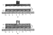
本実施例の色素増感型太陽電池モジュールは、図1及び2に示すように、ガラス製の透光性基板1(厚み1.1mm×100mm×100mm)上に、細長い矩形のセルCが6つ並設された構造をもつ。セルは幅w、厚みtの短冊状であり、透光性基板1上で両端部5mmずつを除き、12mmピッチで形成されている。これらのセルCは電気的に直列に接続されている。セルCの図1における上方には防湿部材としてのラミネートフィルム(7、8、9、8)にて被覆されている。ラミネートフィルムはセルC側から変性低密度ポリエチレンからなる接着性材料層としてのフィルム7、PET製のフィルム8、アルミニウム製の薄膜9、PET製のフィルム8の順に積層されている。フィルム7は直接、中間シール部6に接する部位であり、中間シール部6と同じ材質を採用することで接着性を向上させている(ここで、フィルム7と中間シール部6とを異なる材料にて形成しても良いことはいうまでもないが、フィルム7と中間シール部6とは親和性が高い材料にて形成することが望ましい(以下、同じ))。
(Constitution)
In the dye-sensitized solar cell module of this example, as shown in FIGS. 1 and 2, six elongated rectangular cells C are formed on a glass transparent substrate 1 (thickness 1.1 mm × 100 mm × 100 mm). It has two side-by-side structures. The cells have a strip shape having a width w and a thickness t, and are formed at a pitch of 12 mm on the
セルCは、透明導電膜2(厚み500nm)、受光電極3(厚み10μm)、セパレータ4(厚み5μm)及び対極5(厚み30μm)から構成され、この順に透光性基板1上に積層されている。セルCには流動性を有する電解液が充填されている。電解液は電解質を有機溶媒に溶解したものである。電解質としてはハロゲンであるヨウ素を採用している。ヨウ素はイオンとして存在する。電解液は、対極2の光極に対して反対側から含浸させる。
The cell C is composed of a transparent conductive film 2 (thickness 500 nm), a light receiving electrode 3 (
透明導電膜2は、セルCの境界を越えて図1における右方に延設されており、右側に隣接するセルCの対極5に接続されている。対極5はセルCの左方の端部を通って透明導電膜2側にまで形成され左側に隣接するセルCから延設された透明導電膜2に接続される。
The transparent
透明導電膜2及び受光電極3は合わせて光極としての機能を発揮する。透明導電膜2は、FまたはSbをドープしたSnO2 膜、あるいは、ITO膜で形成されている。受光電極3は多孔質のN型の半導体(アナターゼ型酸化チタン)に光増感色素(光照射による電子放出性をもつ)を担持して形成されている。
The transparent
セパレータ4は受光電極3と対極5との間に配置されており、ルチル型の酸化チタンの多孔質体からなる。
The
対極5は受光電極3に対して所定の間隔を隔てて対面している。対極5は、カーボン微粒子から形成されている。対極5はヨウ素に対して耐食性が高く且つ導電性を有するカーボンや、金属で形成することができる。例えばチタン、タンタル、ニオブ、タングステン、白金等を用いることができる。
The
セルCはリブ状の中間シール部6により区画されている。中間シール部6は、セルCの間に形成されており、その中間シール部6の図面左方のセルCから延設される透明導電膜2と防湿部材との間を接続している。中間シール部6は変性低密度ポリエチレンから構成されており、ラミネートフィルムのフィルム7との接着性に優れている。中間シール部6は、シリカから形成され、セルCの厚みtより僅かに大きい径(50μm)をもつ球状のスペーサを10質量%含んでおり、厚み方向から加えられる力により、自身及びセルCが変形することを抑えている。
The cell C is partitioned by a rib-shaped
6つのセルCの周囲には外周シール部61が設けられている。外周シール部61は中間シール部6と同じ材料で形成されている。なお、中間シール部6、外周シール部61及びフィルム7を構成する変性低密度ポリエチレンには接着性官能基としてカルボキシ基が導入されている。
An outer
(製造方法)
図3に示すように、透光性基板1上に透明導電膜2を形成した後(図3(a))、セルC間の不必要な部分をスクライビングして除去している(図3(b))。透明導電膜2のスクライビングは、透光性基板1としてガラス基板を採用した場合にはYAGレーザー、CO2レーザーなどにて、樹脂基板を採用した場合にはピンなどにて行うことができる。
(Production method)
As shown in FIG. 3, after forming the transparent
透明導電膜2を形成後、受光電極3、セパレータ4及び対極5をスクリーン印刷により印刷することで順次形成する。つまり、所定位置にスクリーン印刷にて印刷後、乾燥させる工程を受光電極3、セパレータ4及び対極5の順で行い積層して形成した。
After forming the transparent
ここで、受光電極3は平均粒径20nmのアナターゼ型酸化チタン微粒子を、セパレータ4は平均粒径280nmのルチル型酸化チタン微粒子を、そして、対極5はカーボン微粒子を用いている。受光電極3は厚みが10μm、セパレータ4は厚みが5μm、対極5は厚みが30μmであった。。
Here, the
その後、アセトニトリル・t−ブタノール混合溶液に溶解させた光増感色素を受光電極3に染み込ませて吸着させた。その後、中間シール部6を形成した(図3(c))。そして、対極5の背面側から電解液を含浸させた。
Thereafter, a photosensitizing dye dissolved in an acetonitrile / t-butanol mixed solution was soaked into the
中間シール部6は、変性低密度ポリエチレンをディスペンサなどの定量塗布装置にて形成した。定量塗布装置は180℃に加熱した変性低密度ポリエチレンをセルC間及びセルCの周囲に塗布した。中間シール部6はその他、加熱型のスクリーン印刷(実施例1−2)や、予め中間シール部6の形状に成形して配設(実施例1−3)することもできる。
The
その後、防湿部材にて被覆した。中間シール部6は、防湿部材を介して溶融温度にまで加熱することで接着を完了させている。この変性低密度ポリエチレンは接着性官能基としてカルボキシ基を有しているので、接着性に優れる。
Then, it covered with a moisture-proof member. The
なお、熱硬化性の接着性官能基を有する場合には熱硬化が発現する所定温度にまで加熱することで熱硬化させる。光硬化性の接着性官能基を有する場合には光を照射することで硬化させる。 In addition, when it has a thermosetting adhesive functional group, it thermosets by heating to the predetermined temperature which thermosetting develops. When it has a photocurable adhesive functional group, it is cured by irradiation with light.
中間シール部6を加熱する方法は、図4に示すように、加熱金型92を採用することができる。まず、透光性基板1上にすべての構成要素を配置して接着する直前まで工程が進行した後に、定盤91上に載置した後、上方から加熱金型92にて加熱して接着する。加熱金型92は中間シール部6の形状に合わせて形成された突起が設けられており、中間シール部6以外の部分には圧力が加えられないようにしている。加圧条件は60kg、数秒間とした。
As a method for heating the
更に、定盤91及び加熱金型92を用いて加圧を行う方法に替えて、加熱された1組のロールにより順次、狭持することで加圧することができる(実施例1−4)。ローラによる加圧条件は線圧500kg、ローラ表面温度180℃、速度50mm/分にて行った。
Furthermore, it can replace with the method of performing pressurization using the
本実施例の色素増感型太陽電池モジュールは中間シール部6を構成する材料が熱硬化型ポリイソブチレンであること、分子量が低く常温で流体状であること、更に、接着性材料層としてのフィルム7は熱硬化型ポリイソブチレンに対して親和性が高い熱硬化型ポリイソブチレン系材料から形成されていること以外は実施例1と同様の構成をもつ。
In the dye-sensitized solar cell module of this example, the material constituting the
中間シール部6がセルC間に配置されたときに流体状なので、本実施例の太陽電池モジュールを製造するにあたり、作業が簡単になるとともに、密着性が向上できる。更には熱硬化が進行する温度を低温にすることもできるので、セルCを構成する他の要素に熱による悪影響を与えるおそれが少なくなる。
When the
本実施例の色素増感型太陽電池モジュールは中間シール部6を構成する材料が紫外線硬化型ポリイソブチレンであること、分子量が低く常温で流体状であること、更に、接着性材料層としてのフィルム7は紫外線硬化型ポリイソブチレンに対して親和性が高い紫外線硬化型ポリイソブチレン系材料から形成されていること以外は実施例1と同様の構成をもつ。
In the dye-sensitized solar cell module of the present embodiment, the material constituting the
紫外線照射は透光性基板1側から行い、中間シール部6及び外周シール部61以外には紫外線が照射されないように遮蔽した上で行う。
The ultraviolet ray irradiation is performed from the
中間シール部6がセルC間に配置されたときに流体状なので、本実施例の太陽電池モジュールを製造するにあたり、作業が簡単になるとともに、密着性が向上できる。更には一般的に紫外線硬化は進行が速いので作業性が向上する。
When the
本実施例の色素増感型太陽電池モジュールは防湿部材中のアルミニウム製の薄膜9に替えてアルミニウム蒸着膜(実施例4−1)又はシリカ蒸着膜(実施例4−2)を採用した以外は実施例1と同様の構成をもち、実施例1と同様の製造方法にて製造されている。 The dye-sensitized solar cell module of this example was replaced with an aluminum vapor deposition film (Example 4-1) or a silica vapor deposition film (Example 4-2) in place of the aluminum thin film 9 in the moisture-proof member. It has the same configuration as that of the first embodiment and is manufactured by the same manufacturing method as that of the first embodiment.
本実施例の色素増感型太陽電池モジュールは実施例1と同じ構成をもち、製造においても中間シール部6及び外周シール部61を加熱する機構が異なる以外は同様の方法にて製造される。つまり、中間シール部6及び外周シール部61がある部分に対して、透明導電膜2が吸収できる波長のYAGレーザにて照射することで透明導電膜2が加熱され、その熱で中間シール部6及び外周シール部61も加熱されることで、融解して熱接着が完了する。中間シール部6及び外周シール部61を構成する材料に熱融着材料又は熱硬化(熱架橋)性材料を採用した上で、対応するレーザの波長を吸収できる物質を含有させることでも同様の製造方法が適用できるようになる。
The dye-sensitized solar cell module of this example has the same configuration as that of Example 1, and is manufactured by the same method except that the mechanism for heating the
[比較例]
本比較例の太陽電池モジュールは中間シール部6を設けていないこと、ロールの温度を180℃としたこと以外は実施例1−4と同様の構成・製造方法にて製造した。
[Comparative example]
The solar cell module of this comparative example was manufactured by the same configuration and manufacturing method as Example 1-4 except that the
[試験]
製造した各実施例及び比較例の太陽電池モジュールについて、モジュール温度25℃でキセノンランプにて照射強度100mW/cm2で光照射することで開放電圧Vocを測定した。その結果、各実施例の太陽電池モジュールはいずれも開放電圧4.5Vを示した。この値は同構成の単セルの開放電圧が0.75Vであることから、各セルC間の電解質のブリッジ発生がなかったことがわかった。この値は3ヶ月間屋外に放置した後でもいずれも変化せず、高い安定性を示すことがわかった。
[test]
About the manufactured solar cell module of each Example and Comparative Example, the open circuit voltage Voc was measured by irradiating light with an irradiation intensity of 100 mW / cm 2 with a xenon lamp at a module temperature of 25 ° C. As a result, all the solar cell modules of the respective examples exhibited an open circuit voltage of 4.5V. This value indicates that there was no electrolyte bridge between the cells C because the open voltage of the single cell having the same configuration was 0.75V. This value did not change even after being left outdoors for 3 months, indicating high stability.
それに対して、比較例の太陽電池モジュールでは開放電圧が0から2.3Vの間でばらつきが発生した。これは隣接するセルC間のシール性が充分でなく、マイクロショートが発生したためと推察できる。 On the other hand, in the solar cell module of the comparative example, variation occurred between the open circuit voltage of 0 and 2.3V. It can be inferred that this is because the sealing property between the adjacent cells C is not sufficient, and a micro short circuit occurs.
以上説明したように、中間シール部を設けることで、高いシール性が発揮でき、高い性能を持続できる太陽電池モジュールを提供できることがわかった。この利点は接着性官能基により接着性が改善されていたことにも由来すると推測される。 As described above, it was found that by providing the intermediate seal portion, it is possible to provide a solar cell module that can exhibit high sealing performance and can maintain high performance. This advantage is presumed to be derived from the fact that the adhesion was improved by the adhesive functional group.
1…透光性基板 2…透明導電膜 3…受光電極 4…セパレータ 5…対極 6…中間シール部 61…外周シール部 7、8、9…ラミネートフィルム 91…定盤 92…加熱金型
DESCRIPTION OF
Claims (8)
前記透光性基板の前記受光面側に対して反対側の面に、透明導電膜及び受光電極から構成される光極と、前記光極の前記受光面の反対側に所定間隔を隔てて対面する対極と、前記光極及び前記対極の間を充填する電解質と、を備えるセルが複数個電気的に直列に接続されて並設された発電部と、
前記発電部の前記受光面側に対して反対側の面を被覆し、前記発電部を防湿する防湿部材と、
前記複数のセル間には前記セル間を区画するリブ状の中間シール部を有する色素増感型太陽電池モジュールを製造する方法であって、
前記中間シール部には、前記透光性基板及び前記防湿部材の間の距離を規制するスペーサを含み、
複数の前記セルを前記透光性基板上に載置した後に、前記中間シール部が配設される部位に流体状乃至は固体状の接着性材料を載置する工程と、
前記接着材料を載置する工程の後に、前記防湿部材を重ね合わせる工程と、
前記防湿部材を重ね合わせる工程の後に、前記中間シール部が配設される部位を加熱して前記中間シール部を形成する工程と、を有することを特徴とする太陽電池モジュールの製造方法。 A translucent substrate provided on the light-receiving surface side of the module;
On the opposite side with respect to the light receiving surface side of the translucent substrate, and composed light pole of a transparent conductive film and the light-receiving electrode, facing at a predetermined distance on the opposite side of the light receiving surface of the light pole a counter electrode to the electrolyte filling between the optical electrode and the counter electrode, and a power generating unit cells are arranged in parallel are connected in series several electrical double comprising,
A moisture barrier member overturned be a surface opposite to moisture the power generation unit to the light-receiving surface side of the power generating unit,
Between prior Symbol plurality of cells to a method of manufacturing a solar cell module sensitized with an intermediate sealing portion rib-like partitioning between the cells,
The intermediate seal portion includes a spacer that regulates a distance between the translucent substrate and the moisture-proof member,
A plurality of said cells after placed on the translucent substrate, the fluid-like or is at a site before Symbol intermediate seal portion is provided comprising the steps of placing a solid adhesive material,
After the step of placing the adhesive material, the step of overlapping the moisture-proof member,
And a step of heating the portion where the intermediate seal portion is disposed to form the intermediate seal portion after the step of stacking the moisture-proof members .
加熱した前記金型にて加圧する工程の替わりに、特定波長のレーザを照射して前記中間シール部を加熱・接着する工程を有する請求項4に記載の太陽電池モジュールの製造方法。 The adhesive material contains an absorbent that absorbs light of a specific wavelength,
The manufacturing method of the solar cell module of Claim 4 which has the process of irradiating the laser of a specific wavelength and heating and adhere | attaching the said intermediate seal part instead of the process of pressurizing with the said heated metal mold | die.
Priority Applications (1)
| Application Number | Priority Date | Filing Date | Title |
|---|---|---|---|
| JP2005075389A JP4830323B2 (en) | 2005-03-16 | 2005-03-16 | Method for producing dye-sensitized solar cell module |
Applications Claiming Priority (1)
| Application Number | Priority Date | Filing Date | Title |
|---|---|---|---|
| JP2005075389A JP4830323B2 (en) | 2005-03-16 | 2005-03-16 | Method for producing dye-sensitized solar cell module |
Publications (3)
| Publication Number | Publication Date |
|---|---|
| JP2006260899A JP2006260899A (en) | 2006-09-28 |
| JP2006260899A5 JP2006260899A5 (en) | 2010-11-04 |
| JP4830323B2 true JP4830323B2 (en) | 2011-12-07 |
Family
ID=37099904
Family Applications (1)
| Application Number | Title | Priority Date | Filing Date |
|---|---|---|---|
| JP2005075389A Expired - Fee Related JP4830323B2 (en) | 2005-03-16 | 2005-03-16 | Method for producing dye-sensitized solar cell module |
Country Status (1)
| Country | Link |
|---|---|
| JP (1) | JP4830323B2 (en) |
Families Citing this family (6)
| Publication number | Priority date | Publication date | Assignee | Title |
|---|---|---|---|---|
| JP2007042460A (en) * | 2005-08-03 | 2007-02-15 | Ngk Spark Plug Co Ltd | Dye-sensitized solar cell and its sealing method |
| JP2007048674A (en) * | 2005-08-11 | 2007-02-22 | Ngk Spark Plug Co Ltd | Dye-sensitized solar cell and its sealing method |
| KR101035265B1 (en) * | 2009-01-22 | 2011-05-19 | 주식회사 디엠에스 | Dye-sensitized solar cell and menifacturing method thereof |
| KR101531535B1 (en) * | 2009-03-18 | 2015-06-26 | 주식회사 동진쎄미켐 | Dye sensitized solar cell module and method of preparing the same |
| JP5585070B2 (en) * | 2009-12-18 | 2014-09-10 | アイシン精機株式会社 | Dye-sensitized solar cell |
| JP2020155551A (en) * | 2019-03-19 | 2020-09-24 | 積水化学工業株式会社 | Dye-sensitized solar cell with protective layer |
Family Cites Families (7)
| Publication number | Priority date | Publication date | Assignee | Title |
|---|---|---|---|---|
| JP2003068373A (en) * | 2001-08-24 | 2003-03-07 | Aisin Seiki Co Ltd | Dye-sensitized solar cell |
| JP2003086822A (en) * | 2001-09-10 | 2003-03-20 | Aisin Seiki Co Ltd | Solar battery module and method for manufacturing the same |
| JP2003223939A (en) * | 2002-01-29 | 2003-08-08 | Nippon Shokubai Co Ltd | Interlaminar material for solar cell and dye sensitizing solar cell using it |
| JP2004047261A (en) * | 2002-07-11 | 2004-02-12 | Nippon Zeon Co Ltd | Photo-electrode, method of manufacturing photo-electrode and solar battery |
| JP2004362793A (en) * | 2003-06-02 | 2004-12-24 | Enplas Corp | Dye-sensitized solar cell unit, substrate for dye-sensitized solar cell, and sealing structure of dye-sensitized solar cell unit |
| JP4666926B2 (en) * | 2004-02-13 | 2011-04-06 | 住友大阪セメント株式会社 | Dye-sensitized solar cell |
| JP4696459B2 (en) * | 2004-03-22 | 2011-06-08 | パナソニック電工株式会社 | Module aggregate |
-
2005
- 2005-03-16 JP JP2005075389A patent/JP4830323B2/en not_active Expired - Fee Related
Also Published As
| Publication number | Publication date |
|---|---|
| JP2006260899A (en) | 2006-09-28 |
Similar Documents
| Publication | Publication Date | Title |
|---|---|---|
| JP5098186B2 (en) | Method for producing dye-sensitized solar cell and dye-sensitized solar cell | |
| JP4830323B2 (en) | Method for producing dye-sensitized solar cell module | |
| WO2010041729A1 (en) | Functional device and manufacturing method therefor | |
| JP2004292247A (en) | Joining method of glass substrate | |
| KR20110009184A (en) | Photoelectric conversion element module and method for manufacturing photoelectric conversion element module | |
| KR20110037938A (en) | Method for producing dye-sensitized solar cell | |
| US20090242017A1 (en) | Dye-sensitized solar cell | |
| WO2012070338A1 (en) | Sealing structure and production method therefor | |
| JP2006012794A (en) | Photocell and manufacturing method therefor | |
| JP5348475B2 (en) | Solar cell module | |
| JP2015191986A (en) | Dye-sensitized solar cell and method for manufacturing the same | |
| KR101188929B1 (en) | Seal member for photoelectric conversion device, photoelectric conversion device comprising the same and method of preparing the same | |
| JP5510771B2 (en) | Dye-sensitized solar cell | |
| JP2014170617A (en) | Dye-sensitized solar cell, manufacturing method of the same and electronic apparatus | |
| JP2010103094A (en) | Photoelectric conversion device | |
| JP5828034B2 (en) | Dye-sensitized solar cell | |
| WO2014010393A1 (en) | Dye-sensitized solar cell | |
| JP5140938B2 (en) | Dye-sensitized solar cell | |
| JP6561880B2 (en) | Method for producing dye-sensitized solar cell module | |
| US20130340809A1 (en) | Dye-sensitized photovoltaic device and fabrication method for the same | |
| WO2005091425A1 (en) | Dye sensitizing solar cell module and manufacturing method thereof | |
| JP6703574B2 (en) | Electric module and manufacturing method thereof | |
| JP5430264B2 (en) | Method for manufacturing photoelectric conversion device | |
| JP5377128B2 (en) | Photoelectric conversion device and method for manufacturing photoelectric conversion device | |
| JP2005174713A (en) | Photoelectric conversion device structure |
Legal Events
| Date | Code | Title | Description |
|---|---|---|---|
| A621 | Written request for application examination |
Free format text: JAPANESE INTERMEDIATE CODE: A621 Effective date: 20080213 |
|
| A521 | Written amendment |
Free format text: JAPANESE INTERMEDIATE CODE: A523 Effective date: 20100917 |
|
| TRDD | Decision of grant or rejection written | ||
| A01 | Written decision to grant a patent or to grant a registration (utility model) |
Free format text: JAPANESE INTERMEDIATE CODE: A01 Effective date: 20110823 |
|
| A01 | Written decision to grant a patent or to grant a registration (utility model) |
Free format text: JAPANESE INTERMEDIATE CODE: A01 |
|
| A61 | First payment of annual fees (during grant procedure) |
Free format text: JAPANESE INTERMEDIATE CODE: A61 Effective date: 20110905 |
|
| R151 | Written notification of patent or utility model registration |
Ref document number: 4830323 Country of ref document: JP Free format text: JAPANESE INTERMEDIATE CODE: R151 |
|
| FPAY | Renewal fee payment (event date is renewal date of database) |
Free format text: PAYMENT UNTIL: 20140930 Year of fee payment: 3 |
|
| LAPS | Cancellation because of no payment of annual fees |