JP4828954B2 - Power generation / desalination complex plant and operation method thereof - Google Patents

Power generation / desalination complex plant and operation method thereof Download PDF

Info

Publication number
JP4828954B2
JP4828954B2 JP2006033590A JP2006033590A JP4828954B2 JP 4828954 B2 JP4828954 B2 JP 4828954B2 JP 2006033590 A JP2006033590 A JP 2006033590A JP 2006033590 A JP2006033590 A JP 2006033590A JP 4828954 B2 JP4828954 B2 JP 4828954B2
Authority
JP
Japan
Prior art keywords
steam
power generation
amount
gas turbine
desalination
Prior art date
Legal status (The legal status is an assumption and is not a legal conclusion. Google has not performed a legal analysis and makes no representation as to the accuracy of the status listed.)
Active
Application number
JP2006033590A
Other languages
Japanese (ja)
Other versions
JP2006266258A (en
Inventor
功一 後藤
洋一 杉森
Current Assignee (The listed assignees may be inaccurate. Google has not performed a legal analysis and makes no representation or warranty as to the accuracy of the list.)
Toshiba Corp
Original Assignee
Toshiba Corp
Priority date (The priority date is an assumption and is not a legal conclusion. Google has not performed a legal analysis and makes no representation as to the accuracy of the date listed.)
Filing date
Publication date
Application filed by Toshiba Corp filed Critical Toshiba Corp
Priority to JP2006033590A priority Critical patent/JP4828954B2/en
Publication of JP2006266258A publication Critical patent/JP2006266258A/en
Application granted granted Critical
Publication of JP4828954B2 publication Critical patent/JP4828954B2/en
Active legal-status Critical Current
Anticipated expiration legal-status Critical

Links

Images

Classifications

    • YGENERAL TAGGING OF NEW TECHNOLOGICAL DEVELOPMENTS; GENERAL TAGGING OF CROSS-SECTIONAL TECHNOLOGIES SPANNING OVER SEVERAL SECTIONS OF THE IPC; TECHNICAL SUBJECTS COVERED BY FORMER USPC CROSS-REFERENCE ART COLLECTIONS [XRACs] AND DIGESTS
    • Y02TECHNOLOGIES OR APPLICATIONS FOR MITIGATION OR ADAPTATION AGAINST CLIMATE CHANGE
    • Y02ATECHNOLOGIES FOR ADAPTATION TO CLIMATE CHANGE
    • Y02A20/00Water conservation; Efficient water supply; Efficient water use
    • Y02A20/124Water desalination
    • YGENERAL TAGGING OF NEW TECHNOLOGICAL DEVELOPMENTS; GENERAL TAGGING OF CROSS-SECTIONAL TECHNOLOGIES SPANNING OVER SEVERAL SECTIONS OF THE IPC; TECHNICAL SUBJECTS COVERED BY FORMER USPC CROSS-REFERENCE ART COLLECTIONS [XRACs] AND DIGESTS
    • Y02TECHNOLOGIES OR APPLICATIONS FOR MITIGATION OR ADAPTATION AGAINST CLIMATE CHANGE
    • Y02EREDUCTION OF GREENHOUSE GAS [GHG] EMISSIONS, RELATED TO ENERGY GENERATION, TRANSMISSION OR DISTRIBUTION
    • Y02E20/00Combustion technologies with mitigation potential
    • Y02E20/16Combined cycle power plant [CCPP], or combined cycle gas turbine [CCGT]

Description

本発明は、コンバインドサイクル発電設備と、前記発電設備の排出蒸気を利用した造水設備の複合プラント及びその運転方法に関する。   The present invention relates to a combined cycle power generation facility, a combined plant of desalination facilities using exhaust steam of the power generation facility, and an operation method thereof.

最近、コンバインドサイクル発電設備と、この発電設備の排出蒸気を利用して、溶質が溶け込んでいる水から淡水を製造する造水設備を複合した発電造水複合プラントが急増している。   Recently, combined cycle power generation facilities and power generation / desalination complex plants that combine fresh water generation facilities that produce fresh water from water in which solutes are dissolved by using the steam discharged from the power generation facilities are rapidly increasing.

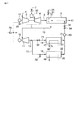
図18は、造水設備として海水を淡水化する場合の発電造水複合プラントの一例を示す構成図である。   FIG. 18 is a configuration diagram showing an example of a power generation / desalination complex plant when seawater is desalinated as a desalination facility.

図18において、コンバインドサイクル発電設備は、ガスタービン1で発電すると同時にガスタービン1の燃焼排ガス8を熱源にして排ガスボイラ9で発生させた蒸気10により稼動する蒸気タービン11で発電するプラントである。   In FIG. 18, the combined cycle power generation facility is a plant that generates power with the gas turbine 1 and simultaneously generates power with the steam turbine 11 that is operated by the steam 10 generated by the exhaust gas boiler 9 using the combustion exhaust gas 8 of the gas turbine 1 as a heat source.

ガスタービン1は、圧縮機2、燃焼器3、膨張機4から構成される。圧縮機2は大気を導入して圧縮し、燃焼用空気6とするものである。燃焼器3は、圧縮された燃焼用空気6により、燃料流量調節弁50を介して流入するガスタービン燃料7を燃焼し、膨張機4を通して高温の燃焼排ガス8を製造する。前記ガスタービン燃料7としては、例えば天然ガスが使用される。ガスタービン1は、燃焼排ガス8により回転し、回転軸に接続された発電機12を運転して発電する。   The gas turbine 1 includes a compressor 2, a combustor 3, and an expander 4. The compressor 2 introduces air and compresses it into combustion air 6. The combustor 3 burns the gas turbine fuel 7 that flows in via the fuel flow control valve 50 by the compressed combustion air 6, and produces high-temperature combustion exhaust gas 8 through the expander 4. As the gas turbine fuel 7, for example, natural gas is used. The gas turbine 1 is rotated by the combustion exhaust gas 8 and operates the generator 12 connected to the rotating shaft to generate power.

さて、膨張機4から排出される燃焼排ガス8は排ガスボイラ9に導かれ、燃焼排ガス8から回収した熱により、給水32を加熱して蒸気10を発生させる。この時、排ガスボイラ9に設けられたダクト燃焼器31により、必要に応じて助燃する。このダクト燃焼器31に供給される例えば天然ガスからなるダクト燃焼器燃料25は、流量調節弁51により流量調節され、助燃量を制御する。ダクト燃焼器31で発生した燃焼排ガス8は冷却されながら排ガスボイラ9を通過し、排気43となって大気に放出される。   The combustion exhaust gas 8 discharged from the expander 4 is guided to the exhaust gas boiler 9, and the steam 10 is generated by heating the feed water 32 with the heat recovered from the combustion exhaust gas 8. At this time, combustion is supplemented as necessary by the duct combustor 31 provided in the exhaust gas boiler 9. The duct combustor fuel 25 made of, for example, natural gas supplied to the duct combustor 31 is adjusted in flow rate by a flow rate adjusting valve 51 to control the auxiliary combustion amount. The combustion exhaust gas 8 generated in the duct combustor 31 passes through the exhaust gas boiler 9 while being cooled, and is discharged into the atmosphere as exhaust 43.

一方、排ガスボイラ9で給水32の加熱により発生した蒸気10を蒸気タービン11に導いて、この蒸気タービン11を回転させ、その回転軸に接続された発電機12を運転して発電する。   On the other hand, the steam 10 generated by heating the feed water 32 in the exhaust gas boiler 9 is guided to the steam turbine 11, the steam turbine 11 is rotated, and the generator 12 connected to the rotating shaft is operated to generate electric power.

蒸気タービン11から排出された排気蒸気13は、流量調節弁52を通して造水設備熱源用蒸気71として造水設備14に導かれ、余剰蒸気15はダンプコンデンサ16に導かれる。造水設備14としては、例えば多段フラッシュ式や多段効用式があるが、図18では多段効用式が採用されている。   The exhaust steam 13 discharged from the steam turbine 11 is guided to the freshwater generation facility 14 as the freshwater generation facility heat source steam 71 through the flow rate control valve 52, and the surplus steam 15 is guided to the dump condenser 16. As the fresh water generation equipment 14, there are, for example, a multi-stage flash type and a multi-stage utility formula, but in FIG. 18, the multi-stage utility formula is adopted.

造水設備14は、タービン排気蒸気13から回収された熱により、海から図示しないポンプにより汲み上げた海水33を蒸発させ、淡水蒸気と濃縮塩水17に分離し、淡水蒸気を凝縮させて淡水26とし、これを例えば図示しないタンク内に集めて飲料水等に供され、また濃縮塩水は海に排出される。   The fresh water generation facility 14 evaporates seawater 33 pumped from the sea by a pump (not shown) by heat recovered from the turbine exhaust steam 13, separates it into fresh water vapor and concentrated salt water 17, and condenses the fresh water vapor into fresh water 26. These are collected, for example, in a tank (not shown) and used for drinking water or the like, and the concentrated salt water is discharged into the sea.

また、ダンプコンデンサ16は、余剰蒸気15を図示しないポンプにより海から汲み上げた冷却用海水35により冷却し復水する復水器で、この復水器で余剰蒸気の冷却に供された冷却海水35は放水48として海に流される。   The dump condenser 16 is a condenser that cools and condenses surplus steam 15 with cooling seawater 35 pumped from the sea by a pump (not shown). Cooling seawater 35 that is used to cool surplus steam in the condenser. Is drained into the sea as water discharge 48.

これら造水設備14の出口から流出する造水設備出口水21とダンプコンデンサ16の出口から流出するダンプコンデンサ出口水22は合流し、ポンプ53によって排ガスボイラ9へ給水弁54を介して給水32として搬送される。   The fresh water facility outlet water 21 flowing out from the outlet of the fresh water facility 14 and the dump condenser outlet water 22 flowing out from the outlet of the dump condenser 16 are merged and supplied to the exhaust gas boiler 9 by the pump 53 as the feed water 32 through the water supply valve 54. Be transported.

ところで、このような構成の発電造水複合プラントは、電気需要と淡水需要を満たすように運転するが、その際、ガスタービン燃料7とダクト燃焼器燃料25の合計消費量をエネルギの有効利用及び経済性の観点から極力少なくすることが好ましい。しかし、電気需要や淡水需要が季節によって変動するので、その年格差の大きな地域では、1年の多くが部分負荷運転期間である。   By the way, the power generation / desalination complex plant having such a configuration is operated so as to satisfy electricity demand and fresh water demand. At that time, the total consumption of the gas turbine fuel 7 and the duct combustor fuel 25 is effectively utilized and It is preferable to reduce as much as possible from the viewpoint of economy. However, since electricity demand and freshwater demand fluctuate depending on the season, most of the year is a partial load operation period in regions where the annual gap is large.

このように前述した発電造水複合プラントにおいては、以下のような2つの課題がある。   Thus, the power generation / desalination complex plant described above has the following two problems.

電気需要と淡水需要の最大値が出力できる構成の発電造水複合プラントにおいて、季節によって変動する電気需要や淡水需要に合わせて、その出力を満足する部分負荷運転を実施する場合、次のようにしている。   In a power generation and desalination complex plant that can output the maximum value of electricity demand and freshwater demand, when performing partial load operation that satisfies the output in accordance with seasonally changing electricity demand or freshwater demand, the following should be done. ing.

ガスタービン1の運転負荷率とダクト燃焼器31の燃焼量を調節して、発電量と淡水量を共に所望値以上にする。また、ガスタービン1が複数台設置されている場合は、ガスタービン1の運転台数と運転負荷率、ダクト燃焼器31の燃焼量を調節する。   The operating load factor of the gas turbine 1 and the combustion amount of the duct combustor 31 are adjusted so that the power generation amount and the fresh water amount are both greater than or equal to desired values. When a plurality of gas turbines 1 are installed, the number of operating gas turbines 1, the operating load factor, and the combustion amount of the duct combustor 31 are adjusted.

この際、排ガスボイラ9とダクト燃焼器31に使用される材料の耐熱性の制約から、全てのダクト燃焼器31の出口温度を許容温度以下にする必要がある。また、適当な調節によってコンバインドサイクルの発電効率を向上させることにより、年間トータルの燃料消費量、即ちガスタービン燃料7とダクト燃焼器燃料25の合計消費量を低減したい。   At this time, it is necessary to set the outlet temperatures of all the duct combustors 31 to an allowable temperature or less because of the heat resistance restriction of the materials used for the exhaust gas boiler 9 and the duct combustor 31. In addition, it is desired to reduce the total annual fuel consumption, that is, the total consumption of the gas turbine fuel 7 and the duct combustor fuel 25 by improving the power generation efficiency of the combined cycle by appropriate adjustment.

また、発電造水複合プラントの運転中、短時間の淡水需要増大に遭遇する場合がある。この場合、発電量を所望値のままで、造水量を増加させるには、ガスタービン1の運転負荷率を下げ、ダクト燃焼器31による助燃量を増やせば実現できる。   Moreover, during the operation of the power generation / desalination complex plant, a short-term increase in demand for fresh water may be encountered. In this case, in order to increase the amount of water produced while maintaining the power generation amount at a desired value, it can be realized by reducing the operating load factor of the gas turbine 1 and increasing the amount of auxiliary combustion by the duct combustor 31.

この場合、淡水需要量が大きいほどダクト燃焼器31の出口温度は高くなるが、この出口温度が許容温度以上になる可能性があるので、運転負荷率を下げないで、造水量を増やしたい。   In this case, the outlet temperature of the duct combustor 31 increases as the fresh water demand increases, but the outlet temperature may be higher than the allowable temperature, so it is desired to increase the amount of water produced without reducing the operating load factor.

また、ダクト燃焼器31による助燃量を増やすのみで、ガスタービン運転負荷率を下げることをしなければ、発電量は蒸気タービン11の発電量増加分、所望値より大きくなるので、発電量不足にはならないが、コンバインドサイクルの合計消費燃料はダクト燃焼器燃料25の増加分、増加するので、ガスタービン運転負荷率を下げたい。なお、ガスタービン1の運転台数は短時間で変更できない。   If the gas turbine operating load factor is not reduced by merely increasing the amount of auxiliary combustion by the duct combustor 31, the power generation amount becomes larger than the desired value by the increase in the power generation amount of the steam turbine 11. However, since the total fuel consumption of the combined cycle increases by the increase of the duct combustor fuel 25, it is desired to reduce the operating load factor of the gas turbine. Note that the number of operating gas turbines 1 cannot be changed in a short time.

本発明は、発電造水複合プラントが季節によって変動する電気需要や淡水需要に併せた部分負荷運転を実施する際、コンバインドサイクルの発電効率を向上させ、年間トータルの燃料消費量を低減することができる発電造水複合プラント及びその運転方法を提供することを目的とする。   The present invention improves the power generation efficiency of the combined cycle and reduces the annual total fuel consumption when the power generation / desalination complex plant performs partial load operation in accordance with the demand for electricity and fresh water that varies depending on the season. An object of the present invention is to provide a power generation / desalination complex plant and an operation method thereof.

本発明は上記の目的を達成するため、以下のような方法及び手段により発電造水複合プラントを運転するものである。   In order to achieve the above object, the present invention operates a power generation / desalination complex plant by the following methods and means.

第1の発明は、ガスタービンの運転負荷率を蒸気タービンのタービン排気蒸気の内、造水設備に使用しない余剰蒸気の単位時間当たりの流量、即ち余剰蒸気量がゼロから予め定められた値までの間となる運転負荷率にして運転する。 According to the first aspect of the present invention, the operating load factor of the gas turbine is set to a flow rate per unit time of surplus steam that is not used in the desalination equipment in the turbine exhaust steam of the steam turbine, that is, the surplus steam amount is from zero to a predetermined value. Operate at a driving load factor between

第2の発明は、ガスタービンの設置台数が複数で、かつ運転台数が調節できる場合は、ガスタービンの運転台数を目標発電量が実現できる最小台数とし、その上でガスタービンの運転負荷率を蒸気タービンの排気蒸気の内、造水設備に使用しない余剰蒸気の単位時間当たりの流量、即ち余剰蒸気量がゼロから予め定められた値までの間となる運転負荷率にして運転する。 In the second aspect of the present invention, when there are a plurality of gas turbines installed and the number of operating units can be adjusted, the number of operating gas turbines is set to the minimum number capable of realizing the target power generation amount, and the operating load factor of the gas turbine is then set. Of the exhaust steam of the steam turbine, the operation is performed at an operating load factor at which the flow rate per unit time of surplus steam that is not used in the desalination equipment, that is, the surplus steam amount is between zero and a predetermined value .

第3の発明は、ガスタービンの運転台数を、目標発電量が実現でき、かつ、排ガスボイラに設置した全てのダクト燃焼器の出口温度が予め定められた値以下になる、最小台数として運転する。 In the third invention, the number of operating gas turbines is operated as the minimum number that can achieve the target power generation amount and the outlet temperatures of all the duct combustors installed in the exhaust gas boiler are equal to or lower than a predetermined value. .

第4の発明は、排ガスボイラから蒸気を抽気し、蒸気タービンのタービン排気蒸気と混合し、造水設備の熱源として利用すると共に、ガスタービンの運転負荷率を目標発電量が実現できる値にする運転に切換可能にする。 In the fourth invention, steam is extracted from the exhaust gas boiler, mixed with the turbine exhaust steam of the steam turbine, and used as a heat source for fresh water generation equipment, and the operating load factor of the gas turbine is set to a value that can achieve the target power generation amount. Enable switching to operation.

本発明によれば、上記のような方法及び手段により発電造水複合プラントを運転することにより、造水設備への熱源用蒸気の必要量と所望発電量とを同時に満足させながら部分負荷運転時の発電効率を最大にすることが可能となるので、季節によって変動する電気需要や淡水需要に併せた部分負荷運転を実施する際、コンバインドサイクルの発電効率を向上させ、年間トータルの燃料消費量を低減することができる。   According to the present invention, by operating the power generation / desalination complex plant by the method and means as described above, at the time of partial load operation while simultaneously satisfying the required amount of steam for the heat source to the desalination facility and the desired power generation amount. The power generation efficiency of the combined cycle can be improved and the annual total fuel consumption can be reduced when performing partial load operation in conjunction with seasonally changing electricity demand and freshwater demand. Can be reduced.

以下本発明の実施形態を図面を参照して説明する。   Embodiments of the present invention will be described below with reference to the drawings.

図1は本発明による発電造水複合プラント及びその運転方法を説明するための第1の実施形態を示す構成図で、図18と同一部分には同一符号を付してその説明を省略し、ここでは異なる点について述べる。   FIG. 1 is a block diagram showing a first embodiment for explaining a power generation / desalination complex plant and its operating method according to the present invention. The same parts as those in FIG. Here are the differences.

図1に示すように、ガスタービン1に接続した発電機12にガスタービン発電機用電力計58を設置し、また、蒸気タービン11からダンプコンデンサ16に流入するタービン排気蒸気13の余剰蒸気量15を計測する流量計70を設置する。   As shown in FIG. 1, a gas turbine generator wattmeter 58 is installed in a generator 12 connected to the gas turbine 1, and the surplus steam amount 15 of the turbine exhaust steam 13 flowing into the dump condenser 16 from the steam turbine 11. A flow meter 70 for measuring the above is installed.

さらに、蒸気タービン11に接続した発電機12及びガスタービン1に接続した発電機12で発電した電力から、ポンプ53等の発電造水複合プラント内の機器運転で消費する電力を差引いた送電端電力値を計測する送電端電力計73を設ける。   Furthermore, the transmission end power obtained by subtracting the power consumed by the operation of the power generation / desalination complex plant such as the pump 53 from the power generated by the generator 12 connected to the steam turbine 11 and the generator 12 connected to the gas turbine 1. A power transmission end wattmeter 73 for measuring the value is provided.

これらガスタービン発電機用電力計58、流量計70及び送電端電力計73でそれぞれ計測されたガスタービン用発電機電力値74と送電端電力値60及び余剰蒸気量30を図2に示すように制御器59に入力する。   As shown in FIG. 2, the gas turbine generator power value 74, the power transmission end power value 60, and the surplus steam amount 30 measured by the gas turbine generator power meter 58, the flow meter 70 and the power transmission end power meter 73, respectively. Input to the controller 59.

この制御器59は、ガスタービン燃料流量調整弁50の開度63及びダクト燃焼器燃料流量調整弁51の開度64を予め図3から得られるガスタービン運転負荷率の特性に基づいて制御するものである。   The controller 59 controls the opening 63 of the gas turbine fuel flow rate adjusting valve 50 and the opening 64 of the duct combustor fuel flow rate adjusting valve 51 based on the characteristics of the gas turbine operating load factor obtained in advance from FIG. It is.

なお、図2においては、3台のガスタービンが設置されていることを想定して示してあるが、図1の例では1台のガスタービン1が設置されているので、ガスタービン用発電機電力値74、ガスタービン燃料流量調整弁50の開度63及びダクト燃焼器燃料流量調整弁51の開度64としてはそれぞれ1つである。   2 shows that three gas turbines are installed, but in the example of FIG. 1, since one gas turbine 1 is installed, a generator for gas turbines is shown. The power value 74, the opening degree 63 of the gas turbine fuel flow rate adjustment valve 50, and the opening degree 64 of the duct combustor fuel flow rate adjustment valve 51 are each one.

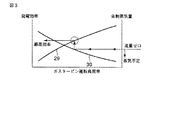
図3はコンバインドサイクルの発電量、即ちガスタービン1と蒸気タービン11の発電量の合計値が所望発電量と一致し、さらにガスタービン1の運転台数(図1の例では1台)を固定した場合のガスタービン1の運転負荷率に対するコンバインドサイクルの発電効率29、余剰蒸気量30の関係を示す特性図である。   FIG. 3 shows that the combined cycle power generation amount, that is, the total power generation amount of the gas turbine 1 and the steam turbine 11 matches the desired power generation amount, and the number of operating gas turbines 1 (one in the example of FIG. 1) is fixed. It is a characteristic view which shows the relationship of the power generation efficiency 29 of a combined cycle, and the surplus steam amount 30 with respect to the operation load factor of the gas turbine 1 in the case.

部分負荷運転時は、ガスタービン1の運転負荷率が100%より低くても所望発電量は発電できる。   During the partial load operation, the desired power generation amount can be generated even if the operation load factor of the gas turbine 1 is lower than 100%.

ガスタービン運転負荷率が高いほど、ガスタービン1の発電量とガスタービン1の排熱による蒸気タービン11の発電量の合計値が、その合計値にダクト燃焼器31の助燃による蒸気タービン11の発電量を加えたコンバインドサイクル発電量に占める比率が大きいので、発電効率29は高くなる。   The higher the gas turbine operation load factor, the higher the total value of the power generation amount of the gas turbine 1 and the power generation amount of the steam turbine 11 due to the exhaust heat of the gas turbine 1, and the total value thereof is the power generation of the steam turbine 11 by the auxiliary combustion of the duct combustor 31. Since the ratio of the combined cycle power generation amount including the amount is large, the power generation efficiency 29 is increased.

また、ガスタービン1の発電量が小さいほど、排ガスボイラ9の助燃量を増やして蒸気タービン11の発電量を増やすことになるので、発生蒸気量は多くなる。よって、ガスタービン運転負荷率が高いほど、タービン排気蒸気13の量は少なく、運転負荷率が充分に低いときは、造水設備14の必要蒸気量より大きくなるので、余剰蒸気量30が多くなる。   Further, the smaller the power generation amount of the gas turbine 1 is, the more the auxiliary combustion amount of the exhaust gas boiler 9 is increased and the power generation amount of the steam turbine 11 is increased. Therefore, as the gas turbine operating load factor is higher, the amount of turbine exhaust steam 13 is smaller, and when the operating load factor is sufficiently low, the amount of surplus steam 30 increases because it is greater than the required steam amount of the fresh water generation facility 14. .

したがって、運転負荷率に対する余剰蒸気量30のグラフは右下がりになる。   Therefore, the graph of the surplus steam amount 30 with respect to the operating load factor falls to the right.

上記とは逆にガスタービン運転負荷率を上げていくと、発電効率29が高くなっていくが、余剰蒸気量30が少なくなり、ある運転負荷率で造水設備14の必要蒸気量が確保できなくなる。造水設備14に対して蒸気不足の場合は、運転不成立となるので、余剰蒸気量30がゼロになるとき、発電効率29は最高になる。   Contrary to the above, when the gas turbine operation load factor is increased, the power generation efficiency 29 increases, but the surplus steam amount 30 decreases, and the necessary steam amount of the fresh water generation facility 14 can be secured at a certain operation load factor. Disappear. When steam is insufficient with respect to the fresh water generation facility 14, the operation is not established. Therefore, when the surplus steam amount 30 becomes zero, the power generation efficiency 29 is maximized.

ガスタービン1の発電出力や燃焼排ガス8の状態値は、大気の温度、湿度、圧力によって変化するが、図3に示す特性は定性的には変化しない。短時間では小さな電気需要の変動もあり、電気需要が大きくなる場合を想定して、ゼロよりわずかに大きい値にしてもよい。この値は発電造水複合プラントの運転者が定めた所定の許容値である。   Although the power generation output of the gas turbine 1 and the state value of the combustion exhaust gas 8 change depending on the atmospheric temperature, humidity, and pressure, the characteristics shown in FIG. 3 do not change qualitatively. There may be a small fluctuation in electricity demand in a short time, and it may be set to a value slightly larger than zero assuming that the electricity demand becomes large. This value is a predetermined allowable value determined by the operator of the power generation / desalination complex plant.

したがって、余剰蒸気量30がゼロから所定許容値の間になるガスタービン運転負荷率で発電造水複合プラントを運転すれば、部分負荷運転時にて最高の発電効率29の運転が実現できることになる。   Therefore, if the power generation / desalination complex plant is operated at a gas turbine operation load factor in which the surplus steam amount 30 is between zero and a predetermined allowable value, the operation with the highest power generation efficiency 29 can be realized during the partial load operation.

次に、このような運転を実現するための作用を説明する。   Next, the operation for realizing such operation will be described.

まず、造水設備熱源用蒸気流量調整弁52の開度は、製造される淡水量の調節により別途制御される。すなわち、製造淡水量を増やしたい場合は蒸気流量調整弁52の開度をより大きく、減らしたい場合は開度をより小さくする。   First, the opening degree of the steam flow adjusting valve 52 for the water source of the fresh water generation facility is separately controlled by adjusting the amount of fresh water produced. That is, when it is desired to increase the amount of fresh water produced, the opening degree of the steam flow rate adjusting valve 52 is increased, and when it is desired to decrease, the opening degree is decreased.

このような制御を実施しながら、制御器59では、余剰蒸気量30がゼロから所定許容値の間となるガスタービン運転負荷率になるようにガスタービン燃料流量調整弁50の開度63を制御し、ガスタービン燃料7の流量を調節する。   While performing such control, the controller 59 controls the opening degree 63 of the gas turbine fuel flow rate adjustment valve 50 so that the surplus steam amount 30 becomes a gas turbine operating load factor between zero and a predetermined allowable value. Then, the flow rate of the gas turbine fuel 7 is adjusted.

ガスタービン運転負荷率は、予め図3に示した特性から得られており、ガスタービン1に関してガスタービン用発電機12の電力値が、定格発電電力値に運転負荷率を掛合わせた値になるように、ガスタービン1のガスタービン燃焼量を調節する。その上で、送電端電力値が所望の発電量になるように、ダクト燃焼器31の燃料流量調整弁51の開度64を制御して、ダクト燃焼器31の燃料25の流量を調節し、ダクト燃焼器31の助燃量を調節する。   The gas turbine operating load factor is obtained in advance from the characteristics shown in FIG. 3, and the power value of the gas turbine generator 12 for the gas turbine 1 is a value obtained by multiplying the rated generated power value by the operating load factor. Thus, the gas turbine combustion amount of the gas turbine 1 is adjusted. Then, the opening 64 of the fuel flow rate adjustment valve 51 of the duct combustor 31 is controlled to adjust the flow rate of the fuel 25 of the duct combustor 31 so that the power transmission end power value becomes a desired power generation amount, The auxiliary combustion amount of the duct combustor 31 is adjusted.

仮に短時間の微量の淡水需要増加があった場合は、熱源用蒸気流量調整弁52の開度を大きくすれば、所定許容値までの値であった余剰蒸気量30が減り、熱源用蒸気の流量を増やすことができる。また、発電造水複合プラント自体の内部の変動にも、同様に対応できる。   If there is an increase in demand for a small amount of fresh water for a short time, increasing the opening of the heat source steam flow rate adjustment valve 52 will reduce the surplus steam amount 30 that was the value up to the predetermined allowable value, and The flow rate can be increased. Moreover, it can respond similarly to the fluctuation | variation inside the power generation / desalination complex plant itself.

上記では造水設備熱源用蒸気流量調整弁52の開度を製造淡水量から制御するようにしたが、造水設備熱源用蒸気71の流量値と温度値と圧力値を計測して熱源用蒸気71のエンタルピを算出し、淡水需要分を造水するのに必要なエンタルピ値と等しくなるように制御してもよい。   In the above description, the opening degree of the steam flow adjustment valve 52 for the water production facility heat source is controlled from the amount of fresh water produced. However, the flow rate value, temperature value, and pressure value of the steam 71 for the water production facility heat source are measured, and the steam for the heat source is measured. The enthalpy of 71 may be calculated and controlled so as to be equal to the enthalpy value required to produce fresh water demand.

また、造水設備熱源用蒸気71の圧力値は、大きく変化しないとして、流量値と温度値のみから造水設備熱源用蒸気71の熱量を算出して、淡水需要分を造水するのに必要な熱量値と等しくなればよく、造水設備熱源用蒸気流量調整弁52の開度を制御してもよい。   Further, assuming that the pressure value of the steam 71 for the fresh water generator does not change greatly, it is necessary to calculate the amount of heat of the steam 71 for the fresh water facility only from the flow rate value and the temperature value and to produce fresh water demand. The opening degree of the steam flow rate adjustment valve 52 for the water production facility heat source may be controlled.

上記第1の実施形態では、ガスタービン1側の発電機12の電力値74を電力計58により計測し監視しながらガスタービン燃料7の流量を調節するようにしたが、ガスタービン1の特性に基づき、運転負荷率の目標値に対応するガスタービン燃料7の流量を算出し、ガスタービン燃料流量調整弁50の開度63を制御してもよい。   In the first embodiment, the flow rate of the gas turbine fuel 7 is adjusted while measuring and monitoring the power value 74 of the generator 12 on the gas turbine 1 side by the wattmeter 58. Based on this, the flow rate of the gas turbine fuel 7 corresponding to the target value of the operating load factor may be calculated, and the opening 63 of the gas turbine fuel flow rate adjustment valve 50 may be controlled.

また、前記では送電端電力値を監視しながら所望発電量に合うようにダクト燃焼器燃料25の流量を調節しているが、発電造水複合プラントの特性に基づき、所望発電量に対応するダクト燃焼器燃料25の流量を算出し、ダクト燃焼器燃料流量調整弁51の開度64を制御してもよい。   In the above, the flow rate of the duct combustor fuel 25 is adjusted so as to match the desired power generation amount while monitoring the power transmission end power value, but the duct corresponding to the desired power generation amount is based on the characteristics of the power generation / desalination complex plant. The flow rate of the combustor fuel 25 may be calculated, and the opening degree 64 of the duct combustor fuel flow rate adjustment valve 51 may be controlled.

さらに、ガスタービン1とダクト燃焼器31の燃焼量はそれぞれガスタービン燃料7とダクト燃焼器燃料25の流量で制御しなくても、燃焼用空気6の流量調節などといった他の方法を用いてもよい。   Further, the combustion amounts of the gas turbine 1 and the duct combustor 31 may not be controlled by the flow rates of the gas turbine fuel 7 and the duct combustor fuel 25, respectively, or other methods such as adjustment of the flow rate of the combustion air 6 may be used. Good.

図1ではガスタービン1、蒸気タービン11、造水設備14がそれぞれ1台の場合について示したが、これら構成機器の台数としては何台であってもよい。   Although FIG. 1 shows the case where each of the gas turbine 1, the steam turbine 11, and the water production facility 14 is one, the number of these constituent devices may be any number.

例えば、図4に示すように3台のガスタービン1を設置した発電造水複合ブラントであっても、前述同様の運転を行うことができる。   For example, even if it is a power generation / desalination composite blunt in which three gas turbines 1 are installed as shown in FIG. 4, the same operation as described above can be performed.

また、図1及び図4では、ダクト燃焼器31の設置箇所として排ガスボイラ9の熱交換器より燃焼排ガス8の流れ方向の上流側としたが、図5に示すように熱交換器部分の途中にダクト燃焼器31を設置してもよい。さらに、図1、図4及び図5では、排ガスボイラ9の燃焼排ガス8の流れ方向に1個のダクト燃焼器31を設置したが、図6に示すように燃焼排ガス8の流れ方向に複数台のダクト燃焼器31、ここでは2台のダクト燃焼器を排ガスボイラ9の高圧過熱器の上流側と、蒸発器の上流側に設置するようにしてもよい。   In FIGS. 1 and 4, the duct combustor 31 is installed on the upstream side in the flow direction of the combustion exhaust gas 8 from the heat exchanger of the exhaust gas boiler 9, but as shown in FIG. You may install the duct combustor 31 in this. Further, in FIG. 1, FIG. 4 and FIG. 5, one duct combustor 31 is installed in the flow direction of the combustion exhaust gas 8 of the exhaust gas boiler 9, but as shown in FIG. The duct combustor 31, here two duct combustors, may be installed upstream of the high-pressure superheater of the exhaust gas boiler 9 and upstream of the evaporator.

さらに、上記のように燃焼排ガス8の流れ方向に複数台のダクト燃焼器31を設置してあっても、これらを全て稼動する必要はなく、例えば図6において蒸気タービン11から排出されるタービン排気蒸気13の温度制御を実施しやすくするために、下流側のダクト燃焼器31の1台のみを稼動するようにしてもよい。   Furthermore, even if a plurality of duct combustors 31 are installed in the flow direction of the combustion exhaust gas 8 as described above, it is not necessary to operate all of them. For example, the turbine exhaust discharged from the steam turbine 11 in FIG. In order to facilitate the temperature control of the steam 13, only one of the downstream duct combustors 31 may be operated.

このように第1の実施形態では、発電造水複合プラントのガスタービン1の運転負荷率を蒸気タービン11のタービン排気蒸気13の内、造水設備14に使用しない余剰蒸気15の単位時間当たりの流量、即ち余剰蒸気量30がゼロから所定許容値の間となる運転負荷率にして運転することにより、部分負荷運転時の発電効率を向上させることができ、年間トータルの燃料消費量を低減することができる。また、ガスタービン1の設置台数が複数で、かつ運転台数が調節できる場合も前述同様の作用効果を得ることができる。   As described above, in the first embodiment, the operation load factor of the gas turbine 1 of the power generation / desalination complex plant is set to the unit time of the surplus steam 15 that is not used in the desalination equipment 14 among the turbine exhaust steam 13 of the steam turbine 11. By operating at a flow rate, that is, an operating load factor in which the surplus steam amount 30 is between zero and a predetermined allowable value, it is possible to improve the power generation efficiency during partial load operation, and to reduce the total fuel consumption annually be able to. Further, when the number of installed gas turbines 1 is plural and the number of operating turbines can be adjusted, the same effect as described above can be obtained.

さて、第1の実施形態では図2に示す制御器59により制御しているが、制御器59を用いない場合でも運転負荷率が適切であればよい。即ち、例えば、季節や時間帯などの期間に応じて運転パラメータを決めておき、造水設備熱源用蒸気流量調節弁52の開度を決めておき、運転してもよい。また、自動制御でなく、運転操作員による制御であってもよい。   Now, in the first embodiment, the control is performed by the controller 59 shown in FIG. 2. However, even when the controller 59 is not used, the operating load factor may be appropriate. That is, for example, the operation parameter may be determined according to a period such as a season or a time zone, and the opening degree of the steam flow control valve 52 for the heat source of the fresh water generation facility may be determined to operate. In addition, control by a driving operator may be used instead of automatic control.

本発明の第2の実施形態を図4乃至図7により説明する。   A second embodiment of the present invention will be described with reference to FIGS.

図4乃至図6は第1の実施形態で述べたのと同様なので、その構成についての説明を省略し、ここでは図7に示す特性図を中心に述べる。   4 to 6 are the same as those described in the first embodiment, description of the configuration will be omitted, and the characteristic diagram shown in FIG. 7 will be mainly described here.

コンバインドサイクルの発電量が所望発電量と一致した場合、コンバインドサイクル発電量に占めるガスタービン発電量の比率が高いほど、発電効率は高い。これはガスタービン発電量とガスタービン排熱による蒸気タービン発電量の合計値が大きく、排ガスボイラ9の助燃燃料25が少なくなるためである。   When the combined cycle power generation amount matches the desired power generation amount, the higher the ratio of the gas turbine power generation amount to the combined cycle power generation amount, the higher the power generation efficiency. This is because the total value of the gas turbine power generation amount and the steam turbine power generation amount by the gas turbine exhaust heat is large, and the auxiliary fuel 25 of the exhaust gas boiler 9 is reduced.

ガスタービン燃料7は、ガスタービン1の発電と蒸気タービン11の発電及び造水設備14に利用されているが、ダクト燃焼器31の燃料25は蒸気タービン11の発電と造水設備14にしか利用できないので、ガスタービン1で燃料が消費されるほど発電効率は高くなる。   The gas turbine fuel 7 is used for the power generation of the gas turbine 1, the power generation of the steam turbine 11, and the fresh water generation facility 14, but the fuel 25 of the duct combustor 31 is used only for the power generation of the steam turbine 11 and the fresh water generation facility 14. Therefore, the power generation efficiency increases as the fuel is consumed in the gas turbine 1.

同じガスタービン発電量の時、ガスタービン運転台数が少ないほどガスタービン運転負荷率は高くなるが、コンバインドサイクルの発電効率はより高くなる。これはガスタービン1の特性上、運転負荷率が高いほど、タービン内部効率が高く、ガスタービン1のシステム熱効率が高いので、ガスタービン燃料7が少なくなるからである。   At the same gas turbine power generation amount, the smaller the number of gas turbines operated, the higher the gas turbine operation load factor, but the power generation efficiency of the combined cycle becomes higher. This is because, due to the characteristics of the gas turbine 1, the higher the operating load factor, the higher the turbine internal efficiency and the higher the system thermal efficiency of the gas turbine 1.

図7は、図3における発電効率28と余剰蒸気量30について、ガスタービン運転台数が多い場合と少ない場合を示した特性図である。   FIG. 7 is a characteristic diagram showing a case where the number of operating gas turbines is large and a case where the number of operating gas turbines is large and the amount of surplus steam 30 in FIG.

図7において、運転台数のより多い時と少ない時の発電効率はそれぞれ発電効率38,39であり、余剰蒸気量はそれぞれ40,41である。余剰蒸気量40,41がゼロになる時にそれぞれ対応するガスタービン運転負荷率での発電効率38,39を比較すると、ガスタービン台数がより少ない時の発電効率39がより高い。   In FIG. 7, the power generation efficiencies when the number of operating units is larger and smaller are the power generation efficiencies 38 and 39, respectively, and the surplus steam amounts are 40 and 41, respectively. When comparing the power generation efficiencies 38 and 39 at the corresponding gas turbine operating load factors when the surplus steam amounts 40 and 41 become zero, the power generation efficiency 39 when the number of gas turbines is smaller is higher.

しかし、ガスタービン運転台数を充分に減らすと、運転負荷率を100%にしても、コンバインドサイクル総発電量や造水量が所望量に不足する状態になる。不足しないぎりぎりの台数が所望発電量を実現できる最小台数であり、台数は状況により異なる。   However, if the number of operating gas turbines is sufficiently reduced, even if the operating load factor is 100%, the combined cycle total power generation amount and the fresh water generation amount are insufficient to the desired amount. The minimum number that does not become insufficient is the minimum number that can achieve the desired power generation amount, and the number varies depending on the situation.

したがって、ガスタービン1の運転台数を所望発電量が実現できる最小台数とし、その上で、余剰蒸気量がゼロまたはゼロよりわずかに大きい値になるガスタービン運転負荷率で発電造水複合プラントを運転することにより、部分負荷運転時にて最高の発電効率の運転が実現できることになる。   Therefore, the number of operating gas turbines 1 is set to the minimum number that can realize the desired power generation amount, and then the power generation / desalination complex plant is operated at a gas turbine operation load factor at which the surplus steam amount is zero or slightly larger than zero. By doing so, the operation with the highest power generation efficiency can be realized during the partial load operation.

そこで、第2の実施形態では、図4乃至図6に示す3組のガスタービン1において、運転台数を所望発電量が実現できる最小台数とし、その上でガスタービン1の運転負荷率を蒸気タービン11の排気蒸気13の内、造水設備14に使用しない余剰蒸気15の単位時間当たりの流量、即ち余剰蒸気量がゼロから所定許容値までの値となる運転負荷率にして、発電造水複合プラントを運転する。この場合、運転していないガスタービン1の燃焼排ガス8が流れる排ガスボイラ9への給水弁54のみ閉じる。   Therefore, in the second embodiment, in the three sets of gas turbines 1 shown in FIGS. 4 to 6, the number of operating units is set to the minimum number that can realize the desired power generation amount, and the operating load factor of the gas turbine 1 is set as the steam turbine. 11, the flow rate per unit time of surplus steam 15 that is not used in the desalination equipment 14, that is, the operating load factor in which the surplus steam amount is a value from zero to a predetermined allowable value, Operate the plant. In this case, only the water supply valve 54 to the exhaust gas boiler 9 through which the combustion exhaust gas 8 of the gas turbine 1 not operating flows is closed.

図4乃至図6ではガスタービン1が3台で蒸気タービン11と造水設備14がそれぞれ1台の場合について示したが、これらの構成機器の台数としては何台であってもよい。   Although FIG. 4 thru | or FIG. 6 showed about the case where the gas turbine 1 is three units | sets and the steam turbine 11 and the water production equipment 14 are each one units | sets, what number may be sufficient as these units.

このように第2の実施形態では、発電造水複合プラントのガスタービン1の運転台数を所望発電量が実現できる最小台数とし、その上で、余剰蒸気量がゼロまたはゼロよりわずかに大きい値になるガスタービン運転負荷率で運転することにより、部分負荷運転時の発電効率を向上させることができ、年間トータルの燃料消費量を低減することができる。   As described above, in the second embodiment, the number of operating gas turbines 1 of the power generation / desalination complex plant is set to the minimum number that can realize the desired power generation amount, and the surplus steam amount is set to zero or slightly larger than zero. By operating at the gas turbine operating load factor, the power generation efficiency during partial load operation can be improved, and the total annual fuel consumption can be reduced.

本発明の第3の実施形態を図8により説明する。   A third embodiment of the present invention will be described with reference to FIG.

図8は発電造水複合プラントの構成図で、図4と同一部分には同一符号を付してその説明を省略し、ここでは異なる部分について述べる。   FIG. 8 is a configuration diagram of the power generation / desalination complex plant. The same parts as those in FIG. 4 are denoted by the same reference numerals, and the description thereof is omitted. Here, different parts are described.

第3の実施形態では、図8に示すようにダクト燃焼器31の出口に温度計69を設置し、この温度計69により測定されたダクト燃焼器31の出口温度をもとに、発電造水複合プラントを運転するものである。この場合、ガスタービン1の運転台数は、所望発電量が実現でき、かつ排ガスボイラ9に設置した全てのダクト燃焼器31の出口温度が許容温度以下になる最小台数とする。   In the third embodiment, as shown in FIG. 8, a thermometer 69 is installed at the outlet of the duct combustor 31, and based on the outlet temperature of the duct combustor 31 measured by the thermometer 69, A complex plant is operated. In this case, the number of operating gas turbines 1 is the minimum number that can achieve the desired power generation amount and that the outlet temperatures of all the duct combustors 31 installed in the exhaust gas boiler 9 are below the allowable temperature.

なお、ダクト燃焼器31の出口温度は、温度計69からではなく、予め得られている特性値を用いてもよい。   Note that the outlet temperature of the duct combustor 31 may be a characteristic value obtained in advance, not from the thermometer 69.

図9は、ガスタービン運転負荷率に対するダクト燃焼器31の出口温度27を図3に加えた特性図である。   FIG. 9 is a characteristic diagram in which the outlet temperature 27 of the duct combustor 31 with respect to the gas turbine operating load factor is added to FIG. 3.

図9において、ガスタービン運転負荷率が高いほど、蒸気タービン11の負荷分担が減少するので、排ガスボイラ9の助燃量が小さくなり、ダクト燃焼器出口温度27は低くなる。   In FIG. 9, the higher the gas turbine operation load factor, the smaller the load sharing of the steam turbine 11, so the amount of auxiliary combustion in the exhaust gas boiler 9 becomes smaller and the duct combustor outlet temperature 27 becomes lower.

ところで、1台の排ガスボイラ9に設置するダクト燃焼器31の設置箇所は燃焼排ガス8の流れ方向に1箇所だけでなく、図6に示すように2箇所以上でもよい。図9のダクト燃焼器31の出口温度27はダクト燃焼器31が燃焼排ガス8の流れ方向の1箇所のみの場合であるが、図6に示すようにダクト燃焼器31が燃焼排ガス8の流れ方向の2箇所での運転時に、ダクト燃焼器31の1箇所の出口温度27を固定すると、もう1箇所のダクト燃焼器31の出口温度27は、ダクト燃焼器31の1箇所のみの運転時のダクト燃焼器31の出口温度27と同様に右下がりのグラフになる。   By the way, the installation location of the duct combustor 31 installed in one exhaust gas boiler 9 is not limited to one location in the flow direction of the combustion exhaust gas 8, but may be two or more locations as shown in FIG. The outlet temperature 27 of the duct combustor 31 in FIG. 9 is the case where the duct combustor 31 is only at one location in the flow direction of the flue gas 8, but the duct combustor 31 flows in the flow direction of the flue gas 8 as shown in FIG. When the outlet temperature 27 at one location of the duct combustor 31 is fixed during the operation at the two locations, the outlet temperature 27 of the other duct combustor 31 is the duct at the time of operation at only one location of the duct combustor 31. Similar to the outlet temperature 27 of the combustor 31, the graph decreases downward.

さて、ダクト燃焼器31の出口温度27が許容温度以上になった場合、コンバインドサイクルは運転不成立である。また、余剰蒸気量30がゼロであるガスタービン運転負荷率にて、仮にダクト燃焼器31の出口温度27が許容温度以上ならば、造水設備14用の蒸気とダクト燃焼器31の出口温度27の両方を同時に満足するガスタービン運転負荷率はないので、その時のガスタービン運転台数やそれ以下の運転台数では運転不成立である。   Now, when the outlet temperature 27 of the duct combustor 31 becomes more than the allowable temperature, the combined cycle is not established. Further, if the outlet temperature 27 of the duct combustor 31 is equal to or higher than the allowable temperature at the gas turbine operation load factor where the surplus steam amount 30 is zero, the steam for the fresh water generation facility 14 and the outlet temperature 27 of the duct combustor 31 Since there is no gas turbine operating load factor that satisfies both of these simultaneously, the operation is not established with the number of operating gas turbines at that time or the number of operating gas turbines below that.

そこで、ガスタービン1の運転台数を排ガスボイラ9に設置した全てのダクト燃焼器31の出口温度27が許容温度以下になる最小台数として運転する。   Therefore, the number of operating gas turbines 1 is operated as the minimum number in which the outlet temperatures 27 of all the duct combustors 31 installed in the exhaust gas boiler 9 are equal to or lower than the allowable temperature.

このようにして発電造水プラントを運転すれば、排ガスボイラ9とダクト燃焼器31の使用材料の制約を守りながら、部分負荷運転時の発電効率を向上させることにより、年間トータルの燃料消費量を低減することができる。   By operating the power generation and desalination plant in this way, the total annual fuel consumption can be reduced by improving the power generation efficiency during partial load operation while keeping the restrictions on the materials used for the exhaust gas boiler 9 and the duct combustor 31. Can be reduced.

本発明の第4の実施形態を図10により説明する。   A fourth embodiment of the present invention will be described with reference to FIG.

ここでは、図4乃至図6のいずれかの発電造水プラントを対象にして述べる。   Here, the power generation / desalination plant shown in any of FIGS. 4 to 6 will be described.

第4の実施形態では、図4乃至図6のいずれかに示す発電造水複合プラントにおいて、全てのガスタービン1に接続した発電機12にガスタービン発電機用電力計58を設置し、また、蒸気タービン11からダンプコンデンサ16に流入するタービン排気蒸気13の余剰蒸気量を計測する流量計70を設置する。   In the fourth embodiment, in the power generation / desalination complex plant shown in any of FIGS. 4 to 6, gas turbine generator wattmeters 58 are installed in the generators 12 connected to all the gas turbines 1, and A flow meter 70 for measuring the surplus steam amount of the turbine exhaust steam 13 flowing into the dump condenser 16 from the steam turbine 11 is installed.

さらに、図示していないが蒸気タービン11に接続した発電機12及び全てのガスタービン1に接続した発電機12で発電した電力から、ポンプ53等により発電造水複合プラント内で消費する電力を差引いた送電端電力値を計測する送電端電力計を設ける。   Further, although not shown, the power consumed in the power generation / desalination complex plant is subtracted from the power generated by the generator 12 connected to the steam turbine 11 and the generator 12 connected to all the gas turbines 1 by the pump 53 or the like. A transmission end wattmeter for measuring the power transmission end power value is provided.

これらガスタービン発電機用電力計58、流量計70及び送電端電力計でそれぞれ計測されたガスタービン用発電機電力値74と送電端電力値60及び余剰蒸気量30を図10に示すように制御器59に入力する。   The gas turbine generator power value 74, the power transmission end power value 60, and the surplus steam amount 30 measured by the gas turbine generator power meter 58, the flow meter 70, and the power transmission end power meter, respectively, are controlled as shown in FIG. To the instrument 59.

この制御器59は、ガスタービン1に対して発停信号66を与えるとともに、ガスタービン燃料流量調整弁50の開度63及びダクト燃焼器燃料流量調整弁51の開度64を予め図3から得られるガスタービン運転負荷率の特性に基づいて制御するものである。   The controller 59 gives an on / off signal 66 to the gas turbine 1 and obtains the opening 63 of the gas turbine fuel flow adjustment valve 50 and the opening 64 of the duct combustor fuel flow adjustment valve 51 from FIG. 3 in advance. The control is based on the characteristics of the operating load factor of the gas turbine.

次にこの制御器59による発電造水複合プラントの運転について述べる。   Next, the operation of the power generation / desalination complex plant by the controller 59 will be described.

造水設備熱源用蒸気流量調整弁52の開度は、製造される淡水量を調節するように別途制御する。製造される淡水量を増やしたい場合は開度をより大きく、減らしたい場合は開度をより小さくする。   The opening degree of the steam flow adjusting valve 52 for the water production facility heat source is separately controlled so as to adjust the amount of fresh water produced. When it is desired to increase the amount of fresh water produced, the opening degree is increased, and when it is desired to decrease, the opening degree is decreased.

この制御を実施しながら、まずガスタービン1の運転台数が、所望発電量が実現できる最小台数になるように、制御器59からガスタービン1とポンプ53への発停信号66を出す。これにより、最小台数のガスタービン1のみ運転し、他のガスタービンは停止させ、運転していないガスタービン1の燃焼排ガス8が流れる排ガスボイラ9への給水弁54のみ閉じる。   While performing this control, first, the controller 59 issues a start / stop signal 66 to the gas turbine 1 and the pump 53 so that the number of operating gas turbines 1 is the minimum number that can achieve the desired power generation amount. Accordingly, only the minimum number of gas turbines 1 are operated, the other gas turbines are stopped, and only the water supply valve 54 to the exhaust gas boiler 9 through which the combustion exhaust gas 8 of the gas turbine 1 that is not operating flows is closed.

そして、制御器59にて、余剰蒸気量30がゼロから所定許容値の間となるガスタービン運転負荷率になるように全てのガスタービン燃料流量調整弁50の開度63を制御し、全てのガスタービン1の燃焼量を調節する。   Then, the controller 59 controls the openings 63 of all the gas turbine fuel flow rate adjusting valves 50 so that the surplus steam amount 30 becomes a gas turbine operating load factor between zero and a predetermined allowable value. The combustion amount of the gas turbine 1 is adjusted.

ガスタービン運転負荷率は予め、図3に示した特性から得られており、各ガスタービン1に関してガスタービン用発電機電力値が定格発電電力値に運転負荷率を掛合わせた値になるように、各ガスタービン1のガスタービン燃焼量を調節する。その上で送電端電力値60が所望の発電量になるように、ダクト燃焼器燃料流量調整弁51の開度64を制御して、ダクト燃焼器31の助燃量を調節する。   The gas turbine operating load factor is obtained in advance from the characteristics shown in FIG. 3 so that the gas turbine generator power value for each gas turbine 1 is a value obtained by multiplying the rated generated power value by the operating load factor. The gas turbine combustion amount of each gas turbine 1 is adjusted. Then, the opening 64 of the duct combustor fuel flow rate adjustment valve 51 is controlled to adjust the auxiliary combustion amount of the duct combustor 31 so that the power transmission end power value 60 becomes a desired power generation amount.

仮に短時間の微量の淡水需要増加があった場合は、熱源用蒸気流量調整弁52の開度を大きくすれば、所定許容値まであった余剰蒸気量30が減り、熱源用蒸気71の流量を増やすことができる。また、発電造水複合プラント自体の内部の変動にも、同様に対応できる。   If there is an increase in demand for a small amount of fresh water for a short period of time, if the opening degree of the heat source steam flow rate adjustment valve 52 is increased, the surplus steam amount 30 that has reached the predetermined allowable value is reduced, and the flow rate of the heat source steam 71 is reduced. Can be increased. Moreover, it can respond similarly to the fluctuation | variation inside the power generation / desalination complex plant itself.

造水設備熱源用蒸気流量調整弁52の開度は、前記のように製造淡水量から制御しなくても、造水設備熱源用蒸気71の流量値と温度値と圧力値を計測し、熱源用蒸気71のエンタルピを算出し、淡水需要分を造水するのに必要なエンタルピ値と等しくなるように制御してもよい。   The opening degree of the steam flow adjustment valve 52 for the water production facility heat source measures the flow value, the temperature value, and the pressure value of the steam 71 for the water production facility heat source without controlling the production fresh water amount as described above. The enthalpy of the steam 71 for use may be calculated and controlled so as to be equal to the enthalpy value necessary for producing fresh water demand.

また、造水設備熱源用蒸気71の圧力値は大きく変化しないとして、流量値と温度値のみから造水設備熱源用蒸気71の熱量を算出して、淡水需要分を造水するのに必要な熱量値と等しくなればよいとして、開度を制御してもよい。   Further, assuming that the pressure value of the steam 71 for the fresh water generator does not change greatly, the amount of heat of the steam 71 for the fresh water generator is calculated only from the flow rate value and the temperature value, and it is necessary to produce fresh water demand. The opening degree may be controlled as long as it is equal to the calorific value.

さらに、季節や時間帯などの期間に応じて造水設備熱源用蒸気流量調整弁52の開度を定めておき、運転してもよい。   Furthermore, the opening degree of the steam flow rate adjusting valve 52 for the water production facility heat source may be determined according to a period such as a season or a time zone, and the operation may be performed.

前記ではガスタービン用発電機12の電力値を監視しながらガスタービン燃料7の流量を調節しているが、ガスタービン1の特性に基づき、運転負荷率の目標値に対応するガスタービン燃料7の流量を算出し、ガスタービン燃料流量調整弁50の開度を制御してもよい。   In the above, the flow rate of the gas turbine fuel 7 is adjusted while monitoring the power value of the gas turbine generator 12, but based on the characteristics of the gas turbine 1, the gas turbine fuel 7 corresponding to the target value of the operating load factor is adjusted. The flow rate may be calculated and the opening degree of the gas turbine fuel flow rate adjustment valve 50 may be controlled.

さらに、前記では送電端電力値を監視しながら所望発電量に合うようにダクト燃焼器燃料25の流量を調節しているが、発電造水複合プラントの特性に基づき、所望発電量に対応するダクト燃焼器燃料25の流量を算出し、ダクト燃焼器燃料流量調整弁51の開度64を制御してもよい。   Further, in the above, the flow rate of the duct combustor fuel 25 is adjusted so as to match the desired power generation amount while monitoring the power transmission end power value, but the duct corresponding to the desired power generation amount is based on the characteristics of the power generation / desalination complex plant. The flow rate of the combustor fuel 25 may be calculated, and the opening degree 64 of the duct combustor fuel flow rate adjustment valve 51 may be controlled.

さらに、ガスタービン1とダクト燃焼器31の燃焼量はそれぞれガスタービン燃料7とダクト燃焼器燃料25の流量で制御しなくても、燃焼用空気6の流量調節などといった他の方法を用いてもよい。   Further, the combustion amounts of the gas turbine 1 and the duct combustor 31 may not be controlled by the flow rates of the gas turbine fuel 7 and the duct combustor fuel 25, respectively, or other methods such as adjustment of the flow rate of the combustion air 6 may be used. Good.

図4乃至図6では、ガスタービン1が3台で、蒸気タービン11と造水設備14がそれぞれ1台の場合について示したが、これらの構成機器の台数としては何台であってもよい。   FIGS. 4 to 6 show the case where there are three gas turbines 1 and one steam turbine 11 and one water production facility 14, but the number of these components may be any number.

さて、排ガスボイラ9とダクト燃焼器31に使用される材料の耐熱性の制約から、全てのダクト燃焼器31の出口温度を許容温度以下にする必要がある。このような場合は、以下のように制御する。   Now, it is necessary to make the outlet temperature of all the duct combustors 31 below an allowable temperature from the restriction | limiting of the heat resistance of the material used for the exhaust gas boiler 9 and the duct combustor 31. FIG. In such a case, control is performed as follows.

まず、造水設備熱源用蒸気流量調整弁52の開度は、製造される淡水量を調節するように別途制御する。製造淡水量を増やしたい場合は造水設備熱源用蒸気流量調整弁52の開度をより大きく、減らしたい場合は開度をより小さくする。   First, the opening degree of the steam flow rate adjusting valve 52 for a fresh water generator is separately controlled so as to adjust the amount of fresh water produced. When it is desired to increase the amount of production fresh water, the opening degree of the steam flow rate adjusting valve 52 for the water production facility heat source is increased, and when it is desired to decrease, the opening degree is decreased.

この制御を実施しながら、まずガスタービン1の運転台数が、所望発電量が実現でき、かつ、排ガスボイラ9に設置した全てのダクト燃焼器出口温度が許容温度以下になる最小台数になるように、制御器59からガスタービン1とポンプ53への発停信号を出す。この時、ダクト燃焼器出口温度は予め、図9に示した特性から得ている。   While performing this control, first, the number of operating gas turbines 1 is the minimum number that can realize the desired power generation amount and that the temperatures of all duct combustor outlets installed in the exhaust gas boiler 9 are below the allowable temperature. The controller 59 issues a start / stop signal to the gas turbine 1 and the pump 53. At this time, the duct combustor outlet temperature is obtained in advance from the characteristics shown in FIG.

これにより、最小台数のガスタービン1のみ運転し、他のガスタービンは停止させ、運転していないガスタービン1の燃焼排ガス8が流れる排ガスボイラ9への給水弁54のみ閉じる。   Accordingly, only the minimum number of gas turbines 1 are operated, the other gas turbines are stopped, and only the water supply valve 54 to the exhaust gas boiler 9 through which the combustion exhaust gas 8 of the gas turbine 1 that is not operating flows is closed.

そして、制御器59にて、余剰蒸気量30がゼロから所定許容値の間となるガスタービン運転負荷率になるように全てのガスタービン燃料流量調整弁50の開度を制御し、全てのガスタービン1の燃焼量を調節する。   Then, the controller 59 controls the openings of all the gas turbine fuel flow control valves 50 so that the surplus steam amount 30 becomes a gas turbine operating load factor between zero and a predetermined allowable value, The combustion amount of the turbine 1 is adjusted.

ガスタービン運転負荷率は予め、図3に示した特性から得られており、各ガスタービン1に関してガスタービン用発電機12の電力値が、定格発電電力値に運転負荷率を掛合わせた値になるように、各ガスタービン1のガスタービン燃焼量を調節する。その上で送電端電力値が所望の発電量になるように、ダクト燃焼器燃料流量調整弁51の開度を制御して、ダクト燃焼器31の助燃量を調節する。   The gas turbine operating load factor is obtained in advance from the characteristics shown in FIG. 3, and the power value of the gas turbine generator 12 for each gas turbine 1 is set to a value obtained by multiplying the rated generated power value by the operating load factor. Thus, the gas turbine combustion amount of each gas turbine 1 is adjusted. Then, the opening degree of the duct combustor fuel flow rate adjusting valve 51 is controlled so that the auxiliary combustion amount of the duct combustor 31 is adjusted so that the power transmission end power value becomes a desired power generation amount.

仮に短時間の微量の淡水需要増加があった場合は、熱源用蒸気流量調整弁52の開度を大きくすれば、所定許容値まであった余剰蒸気量30が減り、熱源用蒸気71の流量を増やすことができる。また、発電造水複合プラント自体の内部の変動にも、同様に対応できる。   If there is an increase in demand for a small amount of fresh water for a short period of time, if the opening degree of the heat source steam flow rate adjustment valve 52 is increased, the surplus steam amount 30 that has reached the predetermined allowable value is reduced, and the flow rate of the heat source steam 71 is reduced. Can be increased. Moreover, it can respond similarly to the fluctuation | variation inside the power generation / desalination complex plant itself.

このようにして発電造水プラントを運転すれば、排ガスボイラ9とダクト燃焼器31の使用材料の制約を守りながら、部分負荷運転時の発電効率を向上させることにより年間トータルの燃料消費量を低減することができる。また、自動化により誤操作の可能性がなくなり、信頼性が高くなる。   By operating the power generation and desalination plant in this way, the total annual fuel consumption can be reduced by improving the power generation efficiency during partial load operation while keeping the restrictions on the materials used for the exhaust gas boiler 9 and the duct combustor 31. can do. In addition, automation eliminates the possibility of erroneous operation and increases reliability.

本発明の第5の実施形態を図11により説明する。   A fifth embodiment of the present invention will be described with reference to FIG.

ここでは、図4乃至図6のいずれかの発電造水プラントを対象にして述べる。   Here, the power generation / desalination plant shown in any of FIGS. 4 to 6 will be described.

第5の実施形態では、図4乃至図6のいずれかに示す発電造水複合プラントにおいて、全てのガスタービン1に接続した発電機12にガスタービン発電機用電力計58を設置し、また、蒸気タービン11からダンプコンデンサ16に流入するタービン排気蒸気13の余剰蒸気量を計測する流量計70を設置し、さらに全てのダクト燃焼器31の出口に温度計69を設置する。   In the fifth embodiment, in the power generation / desalination complex plant shown in any of FIGS. 4 to 6, gas turbine generator wattmeters 58 are installed in the generators 12 connected to all the gas turbines 1, and A flow meter 70 for measuring the surplus steam amount of the turbine exhaust steam 13 flowing into the dump condenser 16 from the steam turbine 11 is installed, and thermometers 69 are installed at the outlets of all the duct combustors 31.

さらに、図示していないが蒸気タービン11に接続した発電機12及び全てのガスタービンに接続した発電機12で発電した電力から、ポンプ53等により発電造水複合プラント内で消費する電力を差引いた送電端電力値を計測する送電端電力計を設ける。計測したガスタービン用発電機12の電力値の全てと送電端電力値及び余剰蒸気量30と全てのダクト燃焼器31の出口温度値68は、図11の制御器59に入力される。   Further, although not shown, the power consumed in the power generation / desalination complex plant is subtracted by the pump 53 or the like from the power generated by the generator 12 connected to the steam turbine 11 and the power generator 12 connected to all gas turbines. A power transmission end power meter for measuring the power transmission end power value is provided. All the measured power values of the gas turbine generator 12, the power transmission end power value, the surplus steam amount 30, and the outlet temperature values 68 of all the duct combustors 31 are input to the controller 59 of FIG. 11.

この制御器59は、ガスタービン1に対して発停信号を与えるとともに、ガスタービン燃料流量調整弁50の開度63及びダクト燃焼器燃料流量調整弁51の開度64を予め図9から得られるガスタービン運転負荷率の特性に基づいて制御するものである。   The controller 59 gives an on / off signal to the gas turbine 1, and the opening 63 of the gas turbine fuel flow rate adjustment valve 50 and the opening 64 of the duct combustor fuel flow rate adjustment valve 51 are obtained in advance from FIG. The control is based on the characteristics of the gas turbine operating load factor.

次にこの制御器59による発電造水複合プラントの運転について述べる。   Next, the operation of the power generation / desalination complex plant by the controller 59 will be described.

造水設備熱源用蒸気流量調整弁52の開度は、製造される淡水量を調節するように別途制御する。製造される淡水量を増やしたい場合は開度をより大きく、減らしたい場合は開度をより小さくする。   The opening degree of the steam flow adjusting valve 52 for the water production facility heat source is separately controlled so as to adjust the amount of fresh water produced. When it is desired to increase the amount of fresh water produced, the opening degree is increased, and when it is desired to decrease, the opening degree is decreased.

この制御を実施しながら、まずガスタービン1の運転台数が、所望発電量が実現でき、かつ、排ガスボイラ9に設置した全てのダクト燃焼器31の出口温度が許容温度以下になる最小台数になるように、制御器59からガスタービン1への発停信号を出す。この時、ダクト燃焼器31の出口温度は、予め図9に示した特性から得られた値を用いて制御するが、ガスタービン1の特性は経年劣化したり、大気の気温、湿度、圧力が変化したりすると、その値と実際に計測しているダクト燃焼器31の出口温度値の差が大きくなる。   While carrying out this control, the number of operating gas turbines 1 is the minimum number that can achieve the desired power generation amount and that the outlet temperatures of all the duct combustors 31 installed in the exhaust gas boiler 9 are below the allowable temperature. Thus, the start / stop signal from the controller 59 to the gas turbine 1 is output. At this time, the outlet temperature of the duct combustor 31 is controlled using a value obtained in advance from the characteristics shown in FIG. 9, but the characteristics of the gas turbine 1 are deteriorated over time, and the atmospheric temperature, humidity, and pressure are If it changes, the difference between the value and the outlet temperature value of the duct combustor 31 actually measured increases.

そこで、ダクト燃焼器31の出口温度値が許容温度以上になった場合は、ガスタービン1の運転台数として、所望発電量が実現でき、かつ、実測している全てのダクト燃焼器31の出口温度値が許容温度以下になる最小台数になるように、制御器59からガスタービン1への発停信号を出す。   Therefore, when the outlet temperature value of the duct combustor 31 is equal to or higher than the allowable temperature, the desired power generation amount can be realized as the number of operating gas turbines 1 and the outlet temperatures of all the measured duct combustors 31 are obtained. An on / off signal is sent from the controller 59 to the gas turbine 1 so that the value becomes the minimum number that is equal to or lower than the allowable temperature.

これにより、最小台数のガスタービン1のみ運転し、他のガスタービンは停止させ、運転していないガスタービン1の燃焼排ガス8が流れる排ガスボイラ9への給水弁54のみ閉じる。   Accordingly, only the minimum number of gas turbines 1 are operated, the other gas turbines are stopped, and only the water supply valve 54 to the exhaust gas boiler 9 through which the combustion exhaust gas 8 of the gas turbine 1 that is not operating flows is closed.

そして、制御器59にて、余剰蒸気量30がゼロから所定許容値の間となるガスタービン運転負荷率になるように全てのガスタービン燃料流量調整弁50の開度を制御し、全てのガスタービン1の燃焼量を調節する。   Then, the controller 59 controls the openings of all the gas turbine fuel flow control valves 50 so that the surplus steam amount 30 becomes a gas turbine operating load factor between zero and a predetermined allowable value, The combustion amount of the turbine 1 is adjusted.

ガスタービン運転負荷率は予め、図3に示した特性から得られており、各ガスタービン1に関して、ガスタービン用発電機12の電力値が、定格発電電力値に運転負荷率を掛合わせた値になるように各ガスタービン1のガスタービン燃焼量を調節する。   The gas turbine operating load factor is obtained in advance from the characteristics shown in FIG. 3. For each gas turbine 1, the power value of the gas turbine generator 12 is obtained by multiplying the rated generated power value by the operating load factor. The gas turbine combustion amount of each gas turbine 1 is adjusted so that

その上で、送電端電力値が所望の発電量になるように、ダクト燃焼器燃料流量調整弁51の開度を制御して、ダクト燃焼器31の助燃量を調節する。この時、実測しているダクト燃焼器31の出口温度値が許容温度以上にならないことを監視し、許容温度以上になった場合は、ガスタービン1の最小台数の決定ルーチンから、やり直す。   Then, the opening degree of the duct combustor fuel flow rate adjustment valve 51 is controlled so that the power transmission end power value becomes a desired power generation amount, and the auxiliary combustion amount of the duct combustor 31 is adjusted. At this time, it is monitored that the outlet temperature value of the duct combustor 31 that is actually measured does not exceed the allowable temperature, and if it exceeds the allowable temperature, the routine is repeated from the routine for determining the minimum number of gas turbines 1.

仮に短時間の微量の淡水需要増加があった場合は、熱源用蒸気流量調整弁52の開度を大きくすれば、所定許容値までの値であった余剰蒸気量30が減り、熱源用蒸気71の流量を増やすことができる。また、発電造水複合プラント自体の内部の変動にも、同様に対応できる。   If there is an increase in the demand for a small amount of fresh water in a short period of time, if the opening degree of the heat source steam flow rate adjustment valve 52 is increased, the amount of surplus steam 30 that has been a value up to a predetermined allowable value decreases, and the heat source steam 71 The flow rate can be increased. Moreover, it can respond similarly to the fluctuation | variation inside the power generation / desalination complex plant itself.

造水設備熱源用蒸気流量調整弁52の開度は、前記のように製造淡水量から制御しなくても、造水設備熱源用蒸気71の流量値と温度値と圧力値を計測し、熱源用蒸気71のエンタルピを算出し、淡水需要分を造水するのに必要なエンタルピ値と等しくなるように制御してもよい。   The opening degree of the steam flow adjustment valve 52 for the water production facility heat source measures the flow value, the temperature value, and the pressure value of the steam 71 for the water production facility heat source without controlling the production fresh water amount as described above. The enthalpy of the steam 71 for use may be calculated and controlled so as to be equal to the enthalpy value necessary for producing fresh water demand.

また、造水設備熱源用蒸気71の圧力値は大きく変化しないとして、流量値と温度値のみから造水設備熱源用蒸気71の熱量を算出して、淡水需要分を造水するのに必要な熱量値と等しくなればよいとして、開度を制御してもよい。   Further, assuming that the pressure value of the steam 71 for the fresh water generator does not change greatly, the amount of heat of the steam 71 for the fresh water generator is calculated only from the flow rate value and the temperature value, and it is necessary to produce fresh water demand. The opening degree may be controlled as long as it is equal to the calorific value.

さらに、季節や時間帯などの期間に応じて造水設備熱源用蒸気流量調整弁52の開度を定めておき、運転してもよい。   Furthermore, the opening degree of the steam flow rate adjusting valve 52 for the water production facility heat source may be determined according to a period such as a season or a time zone, and the operation may be performed.

前記ではガスタービン用発電機12の電力値を監視しながらガスタービン燃料7の流量を調節しているが、ガスタービン1の特性に基づき、運転負荷率の目標値に対応するガスタービン燃料7の流量を算出し、ガスタービン燃料流量調整弁50の開度を制御してもよい。   In the above, the flow rate of the gas turbine fuel 7 is adjusted while monitoring the power value of the gas turbine generator 12, but based on the characteristics of the gas turbine 1, the gas turbine fuel 7 corresponding to the target value of the operating load factor is adjusted. The flow rate may be calculated and the opening degree of the gas turbine fuel flow rate adjustment valve 50 may be controlled.

さらに、前記では送電端電力値を監視しながら所望発電量に合うようにダクト燃焼器燃料25の流量を調節しているが、発電造水複合プラントの特性に基づき、所望発電量に対応するダクト燃焼器燃料25の流量を算出し、ダクト燃焼器燃料流量調整弁51の開度を制御してもよい。   Further, in the above, the flow rate of the duct combustor fuel 25 is adjusted so as to match the desired power generation amount while monitoring the power transmission end power value, but the duct corresponding to the desired power generation amount is based on the characteristics of the power generation / desalination complex plant. The flow rate of the combustor fuel 25 may be calculated, and the opening degree of the duct combustor fuel flow rate adjustment valve 51 may be controlled.

さらに、ガスタービン1とダクト燃焼器31の燃焼量はそれぞれガスタービン燃料7とダクト燃焼器燃料25の流量で制御しなくても、燃焼用空気6の流量調節などといった他の方法を用いてもよい。   Further, the combustion amounts of the gas turbine 1 and the duct combustor 31 may not be controlled by the flow rates of the gas turbine fuel 7 and the duct combustor fuel 25, respectively, or other methods such as adjustment of the flow rate of the combustion air 6 may be used. Good.

図4乃至図6では、ガスタービン1が3台で、蒸気タービン11と造水設備14がそれぞれ1台の場合について示したが、これらの構成機器の台数としては何台であってもよい。   Although FIG. 4 thru | or 6 showed the case where the number of the gas turbines 1 was three and the number of the steam turbines 11 and the fresh water generation equipment 14 was one, it does not matter as the number of these components.

このようにして発電造水プラントを運転すれば、排ガスボイラ9とダクト燃焼器31の使用材料の制約を守りながら、部分負荷時の発電効率を向上させることにより年間トータルの燃料消費量を低減することができる。また自動化により誤操作の可能性がなくなり、信頼性が高くなる。   If the power generation / desalination plant is operated in this way, the total annual fuel consumption is reduced by improving the power generation efficiency at the partial load while keeping the restrictions on the materials used for the exhaust gas boiler 9 and the duct combustor 31. be able to. In addition, automation eliminates the possibility of erroneous operation and increases reliability.

本発明の第6の実施形態を図12により説明する。   A sixth embodiment of the present invention will be described with reference to FIG.

図12において、図8と同一部分には同一符号を付してその説明を省略し、ここでは異なる部分について述べる。   In FIG. 12, the same parts as those in FIG. 8 are denoted by the same reference numerals, and the description thereof is omitted. Different parts will be described here.

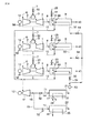
第6の実施形態では、図12に示すように造水設備14を例えば多段フラッシュ式または多段効用式とする。また排ガスボイラ9から抽気した抽気蒸気18の全部あるいは一部をエジェクタ用抽気蒸気(第1の抽気蒸気)56として、造水設備14内のエジェクタ19に導く。   In the sixth embodiment, as shown in FIG. 12, the fresh water generation facility 14 is, for example, a multistage flash type or a multistage utility type. Further, all or a part of the extracted steam 18 extracted from the exhaust gas boiler 9 is guided to the ejector 19 in the fresh water generation facility 14 as ejector extracted steam (first extracted steam) 56.

このエジェクタ19を用いて造水設備14の淡水化ライン内部を減圧し、低圧化により海水33の蒸発を促進する。通過したエジェクタ用抽気蒸気56は濃縮海水17と共に海に排出する。海に排出されたエジェクタ用抽気蒸気56に相当する水は、ダンプコンデンサ16にて補給水44として補給する。   This ejector 19 is used to decompress the inside of the desalination line of the water production facility 14 and promote the evaporation of the seawater 33 by reducing the pressure. The ejector extraction steam 56 that has passed through is discharged into the sea together with the concentrated seawater 17. The water corresponding to the ejector extraction steam 56 discharged to the sea is replenished as make-up water 44 by the dump condenser 16.

そして、余剰蒸気量30がゼロから所定許容値の間となる運転負荷率にして、発電造水複合プラントを運転する。この場合、排ガスボイラ9が製造した蒸気の全てが造水設備用熱源用蒸気71になるわけではないが、ガスタービン運転負荷率が変化してもエジェクタ用抽気蒸気56の流量は大きく変化しないので、図3、図7、図9と同じ特性曲線を描くため、前述した第1乃至第5の実施形態と同様の作用効果が得られる。   Then, the power generation / desalination complex plant is operated at an operating load factor at which the surplus steam amount 30 is between zero and a predetermined allowable value. In this case, not all of the steam produced by the exhaust gas boiler 9 becomes the steam 71 for the heat source for fresh water facilities, but the flow rate of the ejector extraction steam 56 does not change greatly even if the gas turbine operating load factor changes. Since the same characteristic curves as those in FIGS. 3, 7, and 9 are drawn, the same effects as those of the first to fifth embodiments described above can be obtained.

また、図13に示すような排ガスボイラ9の燃焼排ガス8の流れ方向に2台のダクト燃焼器31が設置された構成にしてもよい。   Further, two duct combustors 31 may be installed in the flow direction of the combustion exhaust gas 8 of the exhaust gas boiler 9 as shown in FIG.

図12及び図13では、ガスタービン1が3台で、これら3台全ての抽気蒸気18をエジェクタ用抽気蒸気56として造水設備14に導く配管構成になっているが、1台又は2台のガスタービン1の抽気蒸気18の全部あるいは一部をエジェクタ用抽気蒸気56として造水設備14に導く配管構成にしてもよい。   In FIG.12 and FIG.13, the gas turbine 1 is three units, and it has the piping structure which guides the extraction steam 18 of all these three units to the fresh water generation equipment 14 as the extraction steam 56 for ejectors. A piping configuration may be adopted in which all or part of the extracted steam 18 of the gas turbine 1 is led to the fresh water generation facility 14 as ejector extracted steam 56.

本発明の第7の実施形態を図14により説明する。   A seventh embodiment of the present invention will be described with reference to FIG.

図14において、図12と同一部分には同一符号を付してその説明を省略し、ここでは異なる部分について述べる。   14, the same parts as those in FIG. 12 are denoted by the same reference numerals, and the description thereof is omitted. Different parts will be described here.

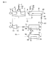
既設の造水設備14に新規のコンバインドサイクル発電設備を接続するときなど、タービン排気蒸気13が造水設備14への必要蒸気圧力より低い場合がある。   In some cases, such as when a new combined cycle power generation facility is connected to the existing freshwater generation facility 14, the turbine exhaust steam 13 may be lower than the required steam pressure to the freshwater generation facility 14.

そこで、本実施形態では、図14に示すように排ガスボイラ9から抽気した抽気蒸気18の全部あるいは一部をサーマルコンプレッサ用抽気蒸気(第2の抽気蒸気)57としてサーマルコンプレッサ23の主流流路に流し、タービン排出蒸気13の一部を喉部から流入させ、これらを合流させた造水設備熱源用蒸気71を造水設備14へ流入するようにしたものである。   Therefore, in this embodiment, as shown in FIG. 14, all or part of the extracted steam 18 extracted from the exhaust gas boiler 9 is used as the thermal compressor extracted steam (second extracted steam) 57 in the main flow path of the thermal compressor 23. Then, a part of the turbine exhaust steam 13 is caused to flow from the throat, and the steam 71 for the fresh water generating facility heat source, which is a combination of these, flows into the fresh water generating facility 14.

このようにすれば、サーマルコンプレッサ23により昇圧されたタービン排気蒸気13の一部と、サーマルコンプレッサ用抽気蒸気57が合流し、造水設備熱源用蒸気71になって造水設備14に流れることで、淡水化の熱源として使用できる。   In this way, a part of the turbine exhaust steam 13 boosted by the thermal compressor 23 and the thermal compressor extraction steam 57 are merged into the fresh water generation equipment heat source steam 71 and flow into the fresh water generation equipment 14. Can be used as a heat source for desalination.

この場合、蒸気タービン11から排出されない抽気蒸気18が、造水設備用熱源用蒸気71の一部になるが、ガスタービン運転負荷率が変化してもサーマルコンプレッサ用抽気蒸気57の流量は大きく変化しないので、図3,図7及び図9と同じ特性曲線を描くため、前述した第1の実施形態乃至第7の実施形態と同様の作用効果が得られる。   In this case, the extracted steam 18 that is not discharged from the steam turbine 11 becomes a part of the steam 71 for the water source for the fresh water generation facility, but the flow rate of the extracted steam 57 for the thermal compressor changes greatly even if the operating load factor of the gas turbine changes. Therefore, since the same characteristic curves as those in FIGS. 3, 7 and 9 are drawn, the same effects as those of the first to seventh embodiments can be obtained.

図14ではガスタービン1が3台で、これら3台全ての抽気蒸気18をサーマルコンプレッサ用抽気蒸気57として造水設備14に導く配管構成になっているが、1台又は2台のガスタービン1の抽気蒸気18の全部あるいは一部をサーマルコンプレッサ用抽気蒸気57として造水設備14に導く配管構成にしてもよい。   In FIG. 14, there are three gas turbines 1, and a piping configuration is adopted in which all of the three extracted steams 18 are led to the fresh water generation facility 14 as the extracted steam 57 for the thermal compressor, but one or two gas turbines 1 are used. A piping configuration may be adopted in which all or part of the extracted steam 18 is led to the fresh water generation facility 14 as the extracted steam 57 for the thermal compressor.

本発明の第8の実施形態を図15により説明する。   An eighth embodiment of the present invention will be described with reference to FIG.

図15において、図12と同一部品には同一不号を付してその説明を省略し、ここでは異なる部分について述べる。   In FIG. 15, the same parts as those in FIG. 12 are denoted by the same reference numerals and the description thereof is omitted, and different parts are described here.

第8の実施形態では、排ガスボイラ9から抽気した抽気蒸気18の全部あるいは一部を造水設備熱源追加用抽気蒸気(第3の抽出蒸気)34として流し、蒸気タービン11のタービン排気蒸気13と混合する配管を設けるとともに、この配管に造水設備熱源追加用抽気蒸気流量弁42を設け、造水設備熱源追加用抽気蒸気58をタービン排気蒸気13と合流させ、造水設備熱源用蒸気71として造水設備14に流入させる構成とするものである。すなわち、造水設備熱源追加用抽気蒸気58の分だけ、造水設備14の熱源が増える。   In the eighth embodiment, all or a part of the extracted steam 18 extracted from the exhaust gas boiler 9 flows as extracted steam (third extracted steam) 34 for fresh water generation facility heat source, and the turbine exhaust steam 13 of the steam turbine 11 and A pipe for mixing is provided, and a water extraction facility heat source addition extraction steam flow valve 42 is provided in this pipe, and the water extraction equipment heat source addition extraction steam 58 is merged with the turbine exhaust steam 13 to form a water generation facility heat source steam 71. It is set as the structure made to flow in into the fresh water generation equipment 14. FIG. That is, the heat source of the fresh water generator 14 is increased by the amount of the extraction steam 58 for adding the fresh water source.

通常は第1の実施形態及び第2の実施形態に示す制御を実施しながら運転している発電造水複合プラントにおいて、所望発電量が変わらず、短時間だけ所望造水量が増加した場合は、造水設備熱源追加用抽気蒸気流量弁42を開き、造水設備熱源用蒸気71を所望造水量が実現できるのに過不足ない流量にし、ガスタービン運転負荷率を所望発電量が実現できる値にして運転する。   Normally, in the power generation and desalination complex plant that is operating while performing the control shown in the first embodiment and the second embodiment, when the desired power generation amount does not change and the desired water generation amount increases only for a short time, Open the extraction steam flow valve 42 for adding a fresh water source, and set the steam 71 for the fresh water source to a flow rate that is sufficient to achieve the desired amount of fresh water, and set the gas turbine operating load factor to a value that can achieve the desired power generation amount. Drive.

この場合、配管に設けた造水設備熱源追加用抽気蒸気流量調整弁42の開度を調節することにより、造水設備14への熱源用蒸気71が不足する場合も過不足なしにでき、この時、余剰蒸気量30はゼロである。   In this case, by adjusting the opening degree of the extraction steam flow rate adjusting valve 42 for adding fresh water to the water production facility provided in the piping, even when the heat source steam 71 to the fresh water production facility 14 is insufficient, it is possible to avoid excess or shortage. At that time, the surplus steam amount 30 is zero.

ここで、コンバインドサイクルの発電効率29と造水設備熱源用抽気蒸気58を、図9に点線で追加した特性図を図16に示す。   Here, FIG. 16 shows a characteristic diagram in which the power generation efficiency 29 of the combined cycle and the extraction steam 58 for the desalination facility heat source are added by dotted lines to FIG.

このような構成としたときの発電効率と造水設備熱源用抽気蒸気58の流量は、それぞれ発電効率45と抽気蒸気量46である。   The power generation efficiency and the flow rate of the water extraction facility heat source extraction steam 58 in such a configuration are the power generation efficiency 45 and the extraction steam amount 46, respectively.

同時にガスタービン運転負荷率を、所望発電量が実現できる値とする。よって、所望発電量が変わらず、短時間だけ所望造水量が増加した場合は、造水設備熱源追加用抽気蒸気流量弁42を開き、造水設備熱源用蒸気71を所望造水量が実現できるのに過不足ない流量にし、かつガスタービン運転負荷率として所望発電量を実現できる値にして運転する。   At the same time, the gas turbine operation load factor is set to a value that can realize the desired power generation amount. Therefore, when the desired power generation amount does not change and the desired water production amount increases for a short time, the extraction steam flow valve 42 for fresh water generation facility heat source addition is opened, and the desired water production amount of the steam 71 for fresh water generation facility heat source can be realized. The gas turbine is operated at a flow rate that is not excessive and insufficient and a value that can realize a desired power generation amount as a gas turbine operation load factor.

この造水設備熱源用抽気蒸気34によりガスタービン1の運転可能なガスタービン運転負荷率の範囲は拡大するが、蒸気タービン11への蒸気量が減少するので発電効率29は、抽気蒸気18がない時の最高効率より低くなる。拡大した運転負荷率は範囲47である。ダクト燃焼器31の出口温度27は運転負荷率が高いほど低いので、この運転切換により許容値以上になることはない。   Although the range of the gas turbine operation load factor at which the gas turbine 1 can be operated is expanded by the extraction steam 34 for the heat source of the fresh water generation facility, the amount of steam to the steam turbine 11 is reduced, so that the power generation efficiency 29 does not include the extraction steam 18. Lower than the highest efficiency of the time. The expanded operating load factor is in the range 47. Since the outlet temperature 27 of the duct combustor 31 is lower as the operating load factor is higher, the operation switching does not exceed the allowable value.

図15ではガスタービン1が3台で、これら3台全ての抽気蒸気18の全部あるいは一部を造水設備熱源追加用抽気蒸気34として造水設備14に導く配管構成になっているが、1台又は2台のガスタービン1の抽気蒸気18を造水設備14に導く配管構成にしてもよい。   In FIG. 15, there are three gas turbines 1, and all or a part of the three extracted steams 18 are connected to the freshwater generation facility 14 as the freshwater generation facility extraction steam 34. A piping configuration may be adopted in which the extracted steam 18 of the two or two gas turbines 1 is led to the fresh water generation facility 14.

本発明の第9の実施形態を図16及び図17により説明する。   A ninth embodiment of the present invention will be described with reference to FIGS.

ここでは、図15の発電造水プラントを対象にして述べる。   Here, the power generation / desalination plant of FIG. 15 will be described.

第9の実施形態では、図15に示す発電造水複合プラントにおいて、全てのガスタービン1に接続した発電機12にガスタービン発電機用電力計58を設置し、また、蒸気タービン11からダンプコンデンサ16に流入するタービン排気蒸気13の余剰蒸気量を計測する流量計70を設置する。   In the ninth embodiment, in the power generation / desalination complex plant shown in FIG. 15, the wattmeters 58 for gas turbine generators are installed in the generators 12 connected to all the gas turbines 1. A flow meter 70 for measuring the surplus steam amount of the turbine exhaust steam 13 flowing into the turbine 16 is installed.

さらに、図示していないが蒸気タービン11に接続した発電機12及び全てのガスタービン1に接続した発電機12で発電した電力から、ポンプ53等により発電造水複合プラント内で消費する電力を差引いた送電端電力値を計測する送電端電力計を設ける。   Further, although not shown, the power consumed in the power generation / desalination complex plant is subtracted from the power generated by the generator 12 connected to the steam turbine 11 and the generator 12 connected to all the gas turbines 1 by the pump 53 or the like. A transmission end wattmeter for measuring the power transmission end power value is provided.

これらガスタービン発電機用電力計58、流量計70及び送電端電力計でそれぞれ計測されたガスタービン用発電機電力値74と送電端電力値60及び余剰蒸気量30、さらに造水設備14から製造淡水量値76を、図17の制御器59に入力する。   Manufactured from the gas turbine generator wattmeter 58, the flow meter 70, and the power transmission end wattmeter, respectively, the gas turbine generator power value 74, the power transmission end power value 60, the surplus steam amount 30, and the fresh water generation equipment 14. The fresh water amount value 76 is input to the controller 59 of FIG.

この制御器59は、ガスタービン1に対して発停信号66を与えるとともに、ガスタービン燃料流量調整弁50の開度63及びダクト燃焼器燃料流量調整弁51の開度64を予め図3から得られるガスタービン運転負荷率の特性に基づいて制御し、また所望発電量が変わらず、短時間だけ所望造水量が増加した場合は造水設備熱源追加用蒸気流量調整弁42の開度67を調整するものである。   The controller 59 gives an on / off signal 66 to the gas turbine 1 and obtains the opening 63 of the gas turbine fuel flow adjustment valve 50 and the opening 64 of the duct combustor fuel flow adjustment valve 51 from FIG. 3 in advance. If the desired amount of generated water does not change and the desired amount of fresh water increases for a short period of time, the opening degree 67 of the steam flow rate adjusting valve 42 for adding fresh water to the water source is adjusted. To do.

次にこの制御器59による発電造水複合プラントの運転について述べる。   Next, the operation of the power generation / desalination complex plant by the controller 59 will be described.

発電造水複合プラントにおいて、通常は第1の実施形態乃至第3の実施形態で述べた制御を実施しながら運転しているとき、所望発電量が変わらず、短時間だけ所望造水量が増加した場合は、以下のように運転する。   In a power generation / desalination complex plant, normally, when operating while performing the control described in the first to third embodiments, the desired power generation amount does not change and the desired water generation amount increases for a short time. If so, drive as follows.

製造淡水量値76が所望造水量になるように、造水設備熱源追加用蒸気流量調整弁43の開度67を調整し、造水設備熱源用蒸気流量71を増加させながら、ガスタービン運転負荷率が所望発電量を実現できる値になるように全てのガスタービン燃料流量調整弁50の開度63を制御し、全てのガスタービン1の燃焼量を調節する。   The gas turbine operating load is adjusted while increasing the steam flow 71 for the fresh water generation facility heat source by adjusting the opening 67 of the steam flow adjustment valve 43 for the fresh water generation facility heat source so that the production fresh water value 76 becomes the desired fresh water generation amount. The opening amounts 63 of all the gas turbine fuel flow rate adjustment valves 50 are controlled so that the rate becomes a value that can realize the desired power generation amount, and the combustion amounts of all the gas turbines 1 are adjusted.

ガスタービン運転負荷率は、予め図3に示した特性から得られており、各ガスタービン1に関してガスタービン用発電機電力値74の値が、定格発電電力値に運転負荷率を掛合わせた値になるように、各ガスタービン1のガスタービン燃焼量を調節する。その上で送電端電力値60が所望の発電量になるように、ダクト燃焼器燃料流量調整弁51の開度64を制御して、ダクト燃焼器31の助燃量を調節する。   The gas turbine operating load factor is obtained in advance from the characteristics shown in FIG. 3, and the value of the gas turbine generator power value 74 for each gas turbine 1 is a value obtained by multiplying the rated generated power value by the operating load factor. The gas turbine combustion amount of each gas turbine 1 is adjusted so that Then, the opening 64 of the duct combustor fuel flow rate adjustment valve 51 is controlled to adjust the auxiliary combustion amount of the duct combustor 31 so that the power transmission end power value 60 becomes a desired power generation amount.

造水設備熱源追加用蒸気流量調整弁42の開度67は、前記のように製造淡水量値76から制御しなくても、造水設備熱源用蒸気71の流量値と温度値と圧力値を計測し、造水設備熱源用蒸気71のエンタルピを算出し、淡水需要分を造水するのに必要なエンタルピ値と等しくなるように制御してもよい。   Even if the opening 67 of the steam flow rate adjusting valve 42 for adding fresh water to the fresh water generating facility is not controlled from the production fresh water value 76 as described above, the flow value, temperature value, and pressure value of the fresh steam 71 for fresh water generating facility are set. You may measure and calculate the enthalpy of the steam 71 for water production equipment heat source, and you may control so that it may become equal to the enthalpy value required in order to produce fresh water demand.

また、造水設備熱源用蒸気71の圧力値は大きく変化しないとして、流量値と温度値のみから造水設備熱源用蒸気71の熱量を算出して、淡水需要分を造水するのに必要な熱量値と等しくなればよいとして、開度を制御してもよい。   Further, assuming that the pressure value of the steam 71 for the fresh water generator does not change greatly, the amount of heat of the steam 71 for the fresh water generator is calculated only from the flow rate value and the temperature value, and it is necessary to produce fresh water demand. The opening degree may be controlled as long as it is equal to the calorific value.

さらに、季節や時間帯などの期間に応じて造水設備熱源用蒸気流量調整弁52の開度を定めておき、運転してもよい。   Furthermore, the opening degree of the steam flow rate adjusting valve 52 for the water production facility heat source may be determined according to a period such as a season or a time zone, and the operation may be performed.

前記ではガスタービン用発電機の電力値74を監視しながらガスタービン燃料7の流量を調節しているが、ガスタービン1の特性に基づき、運転負荷率の目標値に対応するガスタービン燃料7の流量を算出し、ガスタービン燃料流量調整弁50の開度を制御してもよい。   In the above description, the flow rate of the gas turbine fuel 7 is adjusted while monitoring the power value 74 of the gas turbine generator. However, based on the characteristics of the gas turbine 1, the gas turbine fuel 7 corresponding to the target value of the operating load factor is adjusted. The flow rate may be calculated and the opening degree of the gas turbine fuel flow rate adjustment valve 50 may be controlled.

さらに、前記では送電端電力値60を監視しながら所望発電量に合うようにダクト燃焼器31の燃料の流量を調節しているが、発電造水複合プラントの特性に基づき、所望発電量に対応するダクト燃焼器燃料25の流量を算出し、ダクト燃焼器燃料流量調整弁31の開度64を制御してもよい。   Further, in the above, the flow rate of the fuel in the duct combustor 31 is adjusted so as to match the desired power generation amount while monitoring the power transmission end power value 60, but it corresponds to the desired power generation amount based on the characteristics of the power generation / desalination complex plant. The flow rate of the duct combustor fuel 25 to be calculated may be calculated, and the opening degree 64 of the duct combustor fuel flow rate adjustment valve 31 may be controlled.

また、ガスタービン1とダクト燃焼器31の燃焼量はそれぞれガスタービン燃料7とダクト燃焼器燃料25の流量で制御しなくても、燃焼用空気6の流量調節などといった他の方法を用いてもよい。   Further, the combustion amounts of the gas turbine 1 and the duct combustor 31 are not controlled by the flow rates of the gas turbine fuel 7 and the duct combustor fuel 25, respectively, and other methods such as adjusting the flow rate of the combustion air 6 may be used. Good.

図15では、ガスタービン1が3台で、蒸気タービン11と造水設備14がそれぞれ1台の場合について示したが、これらの構成機器の台数としては何台であってもよい。   Although FIG. 15 shows the case where there are three gas turbines 1 and one steam turbine 11 and one fresh water generation facility 14, the number of these components may be any number.

次に本発明による発電造水複合プラントの第10の実施形態を図14により説明する。   Next, a tenth embodiment of the power generation / desalination complex plant according to the present invention will be described with reference to FIG.

図14の構成は前述しているので、その説明は省略し、ここでは所望発電量が変わらず、短時間だけ所望造水量が増加した場合の運転方法について述べる。   Since the configuration of FIG. 14 has been described above, the description thereof will be omitted. Here, an operation method in the case where the desired amount of generated water is increased only for a short time without changing the desired power generation amount will be described.

図14に示すような発電造水複合プラントにおいて、通常は第1の実施形態乃至第3の実施形態で述べた制御を実施しながら運転しているとき、所望発電量が変わらず、短時間だけ所望造水量が増加した場合は、サーマルコンプレッサ用抽気蒸気流量弁62を開き、サーマルコンプレッサ用抽気蒸気57の流量を増やす。   In the power generation / desalination complex plant as shown in FIG. 14, normally, when the operation is performed while performing the control described in the first to third embodiments, the desired power generation amount does not change and only for a short time. When the desired amount of fresh water is increased, the thermal compressor extraction steam flow valve 62 is opened to increase the flow rate of the thermal compressor extraction steam 57.

すると、サーマルコンプレッサ23の喉部から吸込まれる蒸気タービン排出蒸気13の一部の流量も増加する。サーマルコンプレッサ23に吸込まれる蒸気タービン排出蒸気13の一部とサーマルコンプレッサ用抽気蒸気57の合計である造水設備熱源用蒸気71は増える。   Then, the flow rate of a part of the steam turbine exhaust steam 13 sucked from the throat of the thermal compressor 23 also increases. Steam 71 for fresh water generation equipment heat source, which is the sum of part of steam turbine exhaust steam 13 sucked into the thermal compressor 23 and extracted steam 57 for thermal compressor, increases.

これにより、造水設備熱源用蒸気71を所望造水量が実現できるのに過不足ない流量にし、ガスタービン運転負荷率を所望発電量が実現できる値にして運転する。ダクト燃焼器出口温度は運転負荷率が高いほど低いので、この運転切換により許容値以上になることはない。   As a result, the steam 71 for the water production facility heat source is operated at a flow rate that is not excessive or deficient even though the desired amount of fresh water can be realized, and the gas turbine operation load factor is set to a value that can realize the desired power generation amount. Since the duct combustor outlet temperature is lower as the operating load factor is higher, the operation switching does not exceed the allowable value.

図14ではガスタービン1が3台で、これら3台全ての抽気蒸気18の全部あるいは一部をサーマルコンプレッサ用抽気蒸気57として造水設備14に導く配管構成になっているが、1台又は2台のガスタービン1の抽気蒸気18を造水設備14に導く配管構成にしてもよい。   In FIG. 14, there are three gas turbines 1, and all or a part of all three of the extracted steam 18 is connected to the fresh water generation facility 14 as the extracted steam 57 for the thermal compressor. A piping configuration that guides the extracted steam 18 of the gas turbine 1 to the fresh water generation facility 14 may be adopted.

図14では、ガスタービン1が3台で、蒸気タービン11と造水設備14がそれぞれ1台の場合について示したが、これらの構成機器の台数としては何台であってもよい。   Although FIG. 14 shows the case where there are three gas turbines 1 and one each of the steam turbine 11 and the fresh water generation facility 14, the number of these components may be any number.

次に本発明による発電造水複合プラントの第11の実施形態を図14、図16及び図17により説明する。 Next, an eleventh embodiment of the power generation / desalination complex plant according to the present invention will be described with reference to FIGS .

図14に示す発電造水複合プラントにおいて、全てのガスタービン1に接続した発電機12にガスタービン発電機用電力計58を設置し、余剰蒸気量30を計測する流量計70を設置する。図示していないが、蒸気タービン11に接続した発電機12を含む全ての発電機12で発電した電力から、ポンプ53等により発電造水複合プラント24内で消費する電力を差引いた送電端電力値60を計測する送電端電力計を設ける。   In the power generation / desalination complex plant shown in FIG. 14, the gas turbine generator wattmeter 58 is installed in the generator 12 connected to all the gas turbines 1, and the flow meter 70 for measuring the surplus steam amount 30 is installed. Although not shown in figure, the transmission end electric power value which deducted the electric power consumed in the power generation and desalination complex plant 24 by the pump 53 etc. from the electric power generated by all the generators 12 including the generator 12 connected to the steam turbine 11. A power transmission end wattmeter for measuring 60 is provided.

計測したガスタービン用発電機電力値76の全てと送電端電力値60と余剰蒸気量30は、図17の制御器59に入力される。さらに、造水設備14から製造淡水量値76が、制御器59に入力される。   All of the measured gas turbine generator power values 76, the power transmission end power value 60, and the surplus steam amount 30 are input to the controller 59 of FIG. Further, the production fresh water value 76 is input from the fresh water generation facility 14 to the controller 59.

図14に示すような発電造水複合プラントにおいて、通常は第1の実施形態乃至第3の実施形態で述べた制御を実施しながら運転しているとき、所望発電量が変わらず、短時間だけ所望造水量が増加した場合は、以下のように運転する。なお、図17において、造水設備熱源追加用蒸気流量調整弁43の開度67をサーマルコンプレッサ用蒸気流量調整弁62の開度77として述べる。   In the power generation / desalination complex plant as shown in FIG. 14, normally, when the operation is performed while performing the control described in the first to third embodiments, the desired power generation amount does not change and only for a short time. When the desired amount of fresh water is increased, the operation is as follows. In FIG. 17, the opening degree 67 of the steam flow adjustment valve 43 for adding fresh water to the heat generator is described as the opening degree 77 of the steam flow adjustment valve 62 for the thermal compressor.

製造淡水量値76が所望造水量になるように、サーマルコンプレッサ用蒸気流量調整弁62の開度77を調整する。この開度77を大きくすると、サーマルコンプレッサ用抽気蒸気57が増え、サーマルコンプレッサ23の喉部から吸込まれる蒸気タービン排出蒸気13の一部の流量も増加するので、造水設備熱源用蒸気71は増える。   The opening degree 77 of the steam flow rate adjusting valve 62 for the thermal compressor is adjusted so that the production fresh water value 76 becomes the desired fresh water production amount. When this opening degree 77 is increased, the extraction steam 57 for the thermal compressor increases and the flow rate of a part of the steam turbine exhaust steam 13 sucked from the throat of the thermal compressor 23 also increases. Increase.

造水設備熱源用蒸気流量71を増加させながら、ガスタービン運転負荷率が所望発電量を実現できる値になるように全てのガスタービン燃料流量調整弁50の開度63を制御し、全てのガスタービン1の燃焼量を調節する。ガスタービン運転負荷率は、予め図3に示した特性から得られており、各ガスタービン1に関してガスタービン用発電機電力値76の値が、定格発電電力値に運転負荷率を掛合わせた値になるように、各ガスタービン1のガスタービン燃焼量を調節する。その上で送電端電力値60が所望の発電量になるように、ダクト燃焼器燃料流量調整弁51の開度64を制御して、ダクト燃焼器31の助燃量を調節する。   While increasing the steam flow 71 for the water production facility heat source, the openings 63 of all the gas turbine fuel flow control valves 50 are controlled so that the gas turbine operating load factor becomes a value that can realize the desired power generation amount, and all the gases are controlled. The combustion amount of the turbine 1 is adjusted. The gas turbine operating load factor is obtained in advance from the characteristics shown in FIG. 3, and the value of the gas turbine generator power value 76 for each gas turbine 1 is a value obtained by multiplying the rated generated power value by the operating load factor. The gas turbine combustion amount of each gas turbine 1 is adjusted so that Then, the opening 64 of the duct combustor fuel flow rate adjustment valve 51 is controlled to adjust the auxiliary combustion amount of the duct combustor 31 so that the power transmission end power value 60 becomes a desired power generation amount.

サーマルコンプレッサ用蒸気流量調整弁62の開度77は、前記のように製造淡水量値76から制御しなくても、造水設備熱源用蒸気71の流量値と温度値と圧力値を計測し、熱源用蒸気71のエンタルピを算出し、淡水需要分を造水するのに必要なエンタルピ値と等しくなるように制御してもよい。   The opening degree 77 of the steam flow rate adjusting valve 62 for the thermal compressor measures the flow value, the temperature value, and the pressure value of the steam 71 for the water production facility heat source without being controlled from the production fresh water value 76 as described above. The enthalpy of the heat source steam 71 may be calculated and controlled so as to be equal to the enthalpy value necessary for producing fresh water demand.

また、造水設備熱源用蒸気71の圧力値は大きく変化しないとして、流量値と温度値のみから造水設備熱源用蒸気71の熱量を算出して、淡水需要分を造水するのに必要な熱量値と等しくなればよいとして、造水設備熱源用蒸気流量調整弁52の開度を制御してもよい。   Further, assuming that the pressure value of the steam 71 for the fresh water generator does not change greatly, the amount of heat of the steam 71 for the fresh water generator is calculated only from the flow rate value and the temperature value, and it is necessary to produce fresh water demand. The opening degree of the steam flow rate adjustment valve 52 for the fresh water generation facility heat source may be controlled as long as it is equal to the heat value.

さらに、季節や時間帯などの期間に応じて造水設備熱源用蒸気流量調整弁52の開度を定めておき、運転してもよい。   Furthermore, the opening degree of the steam flow rate adjusting valve 52 for the water production facility heat source may be determined according to a period such as a season or a time zone, and the operation may be performed.

前記ではガスタービン用発電機12の電力値を監視しながらガスタービン燃料7の流量を調節しているが、ガスタービン1の特性に基づき、運転負荷率の目標値に対応するガスタービン燃料7の流量を算出し、ガスタービン燃料流量調整弁50の開度を制御してもよい。   In the above, the flow rate of the gas turbine fuel 7 is adjusted while monitoring the power value of the gas turbine generator 12, but based on the characteristics of the gas turbine 1, the gas turbine fuel 7 corresponding to the target value of the operating load factor is adjusted. The flow rate may be calculated and the opening degree of the gas turbine fuel flow rate adjustment valve 50 may be controlled.

さらに、前記では送電端電力値60を監視しながら所望発電量に合うようにダクト燃焼器31の燃料の流量を調節しているが、発電造水複合プラントの特性に基づき、所望発電量に対応するダクト燃焼器燃料25の流量を算出し、ダクト燃焼器燃料流量調整弁31の開度64を制御してもよい。   Further, in the above, the flow rate of the fuel in the duct combustor 31 is adjusted so as to match the desired power generation amount while monitoring the power transmission end power value 60, but it corresponds to the desired power generation amount based on the characteristics of the power generation / desalination complex plant. The flow rate of the duct combustor fuel 25 to be calculated may be calculated, and the opening degree 64 of the duct combustor fuel flow rate adjustment valve 31 may be controlled.

また、ガスタービン1とダクト燃焼器31の燃焼量はそれぞれガスタービン燃料7とダクト燃焼器燃料25の流量で制御しなくても、燃焼用空気6の流量調節などといった他の方法を用いてもよい。   Further, the combustion amounts of the gas turbine 1 and the duct combustor 31 are not controlled by the flow rates of the gas turbine fuel 7 and the duct combustor fuel 25, respectively, and other methods such as adjusting the flow rate of the combustion air 6 may be used. Good.

図14ではガスタービン1が3台で、これら3台全ての抽気蒸気18の全部あるいは一部をサーマルコンプレッサ用抽気蒸気57として造水設備14に導く配管構成になっているが、1台または2台のガスタービン1の抽気蒸気18を造水設備14に導く配管構成にしてもよい。   In FIG. 14, there are three gas turbines 1, and all or a part of the three extracted steams 18 are connected to the fresh water generation equipment 14 as the extracted steam 57 for the thermal compressor. A piping configuration that guides the extracted steam 18 of the gas turbine 1 to the fresh water generation facility 14 may be adopted.

図14では、ガスタービン1が3台で、蒸気タービン11と造水設備14がそれぞれ1台の場合について示したが、これらの構成機器の台数としては何台であってもよい。   Although FIG. 14 shows the case where there are three gas turbines 1 and one steam turbine 11 and one fresh water generation facility 14, the number of these constituent devices may be any number.

前述した第1乃至第11の実施形態では、造水設備14において、海水から淡水を製造する場合について説明したが、海水に代えて排水(汚水)を造水設備14に導入することにより、同様の方法で排水(汚水)から濃縮水と浄水を製造することができる。   In the first to eleventh embodiments described above, the case where fresh water is produced from seawater in the freshwater generation facility 14 has been described. However, the same is achieved by introducing wastewater (sewage) into the freshwater generation facility 14 instead of seawater. Concentrated water and purified water can be produced from waste water (sewage) by this method.

この場合、造水設備14は排水浄化装置として使用され、また冷却用海水の代わりに河川水等を冷却水として使用してもよい。   In this case, the fresh water generation facility 14 is used as a waste water purification device, and river water or the like may be used as cooling water instead of cooling seawater.

このようにすれば、排水(汚水)を浄水にすることができるため、排水処理が可能になるとともに、製造した浄水を有効活用することができる。   If it does in this way, since wastewater (sewage) can be made into purified water, while being able to perform wastewater treatment, the manufactured purified water can be used effectively.

本発明による発電造水複合プラント及びその運転方法を説明するための第1の実施形態を示す構成図。BRIEF DESCRIPTION OF THE DRAWINGS The block diagram which shows 1st Embodiment for demonstrating the power generation desalination complex plant by this invention and its operating method. 同実施の形態における制御を説明するためのブロック図。The block diagram for demonstrating the control in the embodiment. 同実施形態におけるガスタービンの運転負荷率に対するコンバインドサイクルの発電効率、余剰蒸気量の関係を示す特性図。The characteristic view which shows the relationship of the power generation efficiency of a combined cycle with respect to the operation load factor of the gas turbine in the same embodiment, and the amount of surplus steam. 同実施形態において、3台のガスタービンを設置した発電造水複合ブラントの構成図。In the same embodiment, the block diagram of the power generation fresh water composite blunt which installed three gas turbines. 同実施形態の発電造水複合ブラントにおいて、熱交換器部分の途中にダクト燃焼器を設置した発電造水複合ブラントの構成図。In the power generation / desalination complex blunt of the embodiment, a configuration diagram of the power generation / desalination complex blunt in which a duct combustor is installed in the middle of the heat exchanger portion. 同実施形態の発電造水複合ブラントにおいて、燃焼排ガスの流れ方向に複数台のダクト燃焼器を設置した発電造水複合ブラントの構成図。In the power generation / desalination complex blunt of the embodiment, a configuration diagram of the power generation / desalination complex blunt in which a plurality of duct combustors are installed in the flow direction of the combustion exhaust gas. 本発明の第2の実施形態におけるガスタービンの運転負荷率に対するコンバインドサイクルの発電効率、余剰蒸気量の関係についてガスタービン運転台数が多い場合と少ない場合を示す特性図。The characteristic view which shows the case where there are many gas turbine operation numbers about the relationship of the power generation efficiency of a combined cycle with respect to the operation load factor of the gas turbine in the 2nd Embodiment of this invention, and a surplus steam amount. 本発明による発電造水複合プラント及びその運転方法を説明するための第3の実施形態を示す構成図。The block diagram which shows 3rd Embodiment for demonstrating the power generation desalination complex plant by this invention and its operating method. 同実施形態において、図3にガスタービン運転負荷率に対するダクト燃焼器の出口温度を加えた特性図。In the same embodiment, the characteristic view which added the exit temperature of the duct combustor with respect to the gas turbine operation load factor in FIG. 本発明の第4の実施形態における制御を説明するためのブロック図。The block diagram for demonstrating the control in the 4th Embodiment of this invention. 本発明の第5の実施形態における制御を説明するためのブロック図。The block diagram for demonstrating the control in the 5th Embodiment of this invention. 本発明による発電造水複合プラント及びその運転方法を説明するための第6の実施形態を示す構成図。The block diagram which shows 6th Embodiment for demonstrating the power generation desalination complex plant by this invention and its operating method. 同実施形態において、2台のダクト燃焼器が設置された発電造水複合プラントの構成図。The block diagram of the power generation and desalination complex plant in which two duct combustors were installed in the embodiment. 本発明による発電造水複合プラント及びその運転方法を説明するための第7の実施形態を示す構成図。The block diagram which shows 7th Embodiment for demonstrating the power generation desalination complex plant by this invention and its operating method. 本発明による発電造水複合プラント及びその運転方法を説明するための第8の実施形態を示す構成図。The block diagram which shows 8th Embodiment for demonstrating the power generation desalination complex plant by this invention and its operating method. 同実施形態において、図9にコンバインドサイクルの発電効率と造水設備熱源用抽気蒸気を点線で追加して示す特性図。FIG. 10 is a characteristic diagram showing the combined cycle power generation efficiency and fresh water extraction facility extraction steam in FIG. 9 with dotted lines in the same embodiment. 本発明の第9の実施形態における制御を説明するためのブロック図。The block diagram for demonstrating the control in the 9th Embodiment of this invention. 従来の発電造水複合プラント及びその運転方法を説明するための構成例を示す図。The figure which shows the structural example for demonstrating the conventional power generation desalination complex plant and its operating method.

符号の説明Explanation of symbols

1…ガスタービン、2…圧縮機、3…燃焼器、4…膨張機、6…燃焼用空気、7…ガスタービン燃料、8…燃焼排ガス、9…排ガスボイラ、10…蒸気、11…蒸気タービン、12…発電機、13…タービン排気蒸気、14…造水設備、15…余剰蒸気、16…ダンプコンデンサ、17…濃縮塩水、18…抽気蒸気、19…エジェクタ、21…造水設備出口水、22…ダンプコンデンサ出口水、23…サーマルコンプレッサ、25…ダクト燃焼器燃料、26…淡水、27…ダクト燃焼器出口温度、29…コンバインドサイクルの発電効率、30…余剰蒸気量、31…ダクト燃焼器、32…給水、33…海水、34…造水設備熱源追加用抽気蒸気、35…冷却用海水、38…ガスタービン多台数時の発電効率、39…ガスタービン少台数時の発電効率、40…ガスタービン多台数時の余剰蒸気量、41…ガスタービン少台数時の余剰蒸気量、42…造水設備熱源追加用抽気蒸気流量調整弁、43…排気、44…補給水、50…ガスタービン燃料流量調整弁、51…ダクト燃焼器燃料流量調整弁、52…造水設備熱源用蒸気流量調整弁、53…ポンプ、54…給水弁、55…温度計、56…エジェクタ用抽気蒸気、57…サーマルコンプレッサ用抽気蒸気、58…ガスタービン用発電機電力計、59…制御器、60…送電端電力値、61…エジェクタ用抽気蒸気流量調整弁、62…サーマルコンプレッサ用抽気蒸気流量調整弁、63…ガスタービン燃料流量調整弁開度、64…ダクト燃焼器燃料流量調整弁開度、65…造水設備熱源用蒸気流量調整弁開度、66…ガスタービンとポンプの発停信号、67…造水設備熱源追加用抽気蒸気流量調整弁開度、69…温度計、70…流量計、73…送電端電力計、74…ガスタービン用発電機電力値。   DESCRIPTION OF SYMBOLS 1 ... Gas turbine, 2 ... Compressor, 3 ... Combustor, 4 ... Expander, 6 ... Combustion air, 7 ... Gas turbine fuel, 8 ... Combustion exhaust gas, 9 ... Exhaust gas boiler, 10 ... Steam, 11 ... Steam turbine , 12 ... Generator, 13 ... Turbine exhaust steam, 14 ... Fresh water generation equipment, 15 ... Surplus steam, 16 ... Dump condenser, 17 ... Concentrated salt water, 18 ... Extraction steam, 19 ... Ejector, 21 ... Outlet water of fresh water generation equipment, 22 ... Dump condenser outlet water, 23 ... Thermal compressor, 25 ... Duct combustor fuel, 26 ... Fresh water, 27 ... Duct combustor outlet temperature, 29 ... Combined cycle power generation efficiency, 30 ... Excess steam amount, 31 ... Duct combustor 32 ... Water supply, 33 ... Seawater, 34 ... Extraction steam for addition of heat source for fresh water generation equipment, 35 ... Seawater for cooling, 38 ... Power generation efficiency when there are many gas turbines, 39 ... Generation when there are few gas turbines Efficiency: 40: surplus steam amount when there are a large number of gas turbines, 41: surplus steam amount when there are a small number of gas turbines, 42: extraction steam flow rate adjusting valve for adding a heat source for fresh water generation equipment, 43: exhaust, 44: makeup water, 50 DESCRIPTION OF SYMBOLS ... Gas turbine fuel flow rate adjustment valve, 51 ... Duct combustor fuel flow rate adjustment valve, 52 ... Steam flow rate adjustment valve for water source of fresh water generation equipment, 53 ... Pump, 54 ... Water supply valve, 55 ... Thermometer, 56 ... Extraction steam for ejector , 57 ... Extraction steam for thermal compressor, 58 ... Generator wattmeter for gas turbine, 59 ... Controller, 60 ... Power value at transmission end, 61 ... Extraction steam flow adjustment valve for ejector, 62 ... Adjustment of extraction steam flow for thermal compressor Valve, 63 ... Gas turbine fuel flow rate adjustment valve opening, 64 ... Duct combustor fuel flow rate adjustment valve opening, 65 ... Steam flow rate adjustment valve opening for water production facility heat source, 66 ... Gas turbine and pump Chronograph coupling signal, 67 ... desalination facility heat source for the additional extracted steam flow rate adjustment valve opening, 69 ... thermometer, 70 ... flow meter, 73 ... net electric meter, 74 ... generator power value for a gas turbine.

Claims (13)

ガスタービンと、ダクト燃焼器を具備し且つ前記ガスタービンから導入される排ガスの熱により給水を加熱して蒸気を発生させる排ガスボイラと、この排ガスボイラで発生した蒸気を作動流体として稼動させる蒸気タービンとを備えたコンバインドサイクル発電設備に、前記蒸気タービンの排出蒸気を熱源として利用して淡水を製造する造水設備を接続し、前記ガスタービンの運転負荷率と、前記ダクト燃焼器の燃焼量を調節し、発電量と淡水量を共に予め定められた値となるようにする運転を実施する発電造水複合プラントの運転方法において、前記ガスタービンを、前記蒸気タービンの排出蒸気の内、前記造水設備に使用しない余剰蒸気量がゼロから予め定められた値までの間となる運転負荷率で運転し、その際に、前記造水設備で使用しない蒸気の流量を計測して余剰蒸気量を求め、この余剰蒸気量がゼロから予め定められた値までの間となる前記ガスタービンの運転負荷率になるように前記ガスタービンの燃焼量、前記ダクト燃焼器の燃焼量及び前記造水設備に熱源として利用する前記蒸気の流量をそれぞれ制御することを特徴とする発電造水複合プラントの運転方法。 A gas turbine, an exhaust gas boiler that includes a duct combustor and generates steam by heating feed water with heat of exhaust gas introduced from the gas turbine, and a steam turbine that operates steam generated in the exhaust gas boiler as a working fluid And a combined cycle power generation facility connected to a fresh water production facility using the steam discharged from the steam turbine as a heat source, and the operating load factor of the gas turbine and the combustion amount of the duct combustor In the operation method of the power generation / desalination complex plant that performs the operation of adjusting and adjusting both the power generation amount and the amount of fresh water to a predetermined value, the gas turbine is configured to include the generation of the steam discharged from the steam turbine. was driven at a driving load factor excess amount of steam not used for aqueous system is until a predetermined value from zero, when its use in the desalination facility The amount of combustion of the gas turbine is determined so that the surplus steam amount is obtained by measuring the flow rate of the steam, and the surplus steam amount is between zero and a predetermined value. A method for operating a power generation / desalination complex plant, comprising controlling a combustion amount of a duct combustor and a flow rate of the steam used as a heat source for the desalination facility . 複数台数のガスタービンと、ダクト燃焼器を具備し且つ前記ガスタービンから導入される排ガスの熱により給水を加熱して蒸気を発生させる排ガスボイラと、この排ガスボイラで発生した蒸気を作動流体とする蒸気タービンとを備えたコンバインドサイクル発電設備に、前記蒸気タービンの排出蒸気を熱源として利用して淡水を製造する造水設備を接続し、前記ガスタービンの運転台数及び運転負荷率と、前記ダクト燃焼器の燃焼量を調節し、発電量と淡水量を共に予め定められた値となるようにする運転を実施する発電造水複合プラントの運転方法において、前記ガスタービンの運転台数を目標発電量が実現できる最小台数とし、且つ前記ガスタービンを、前記蒸気タービンの排出蒸気の内、前記造水設備に使用しない余剰蒸気量がゼロから予め定められた値までの間となる運転負荷率で運転し、その際に、前記造水設備で使用しない蒸気の流量を計測して余剰蒸気量を求め、この余剰蒸気量がゼロから予め定められた値までの間となる前記ガスタービンの運転負荷率になるように前記ガスタービンの運転台数と燃焼量、前記ダクト燃焼器の燃焼量及び前記造水設備に熱源として利用する前記蒸気の流量をそれぞれ制御することを特徴とする発電造水複合プラントの運転方法。 An exhaust gas boiler having a plurality of gas turbines, a duct combustor and heating the feed water by the heat of the exhaust gas introduced from the gas turbine to generate steam, and the steam generated in the exhaust gas boiler as a working fluid A combined cycle power generation facility equipped with a steam turbine is connected to a desalination facility for producing fresh water using the steam discharged from the steam turbine as a heat source, and the number of operating gas turbines, the operating load factor, and the duct combustion In the operation method of the power generation / desalination complex plant that performs the operation of adjusting the combustion amount of the steam generator so that both the power generation amount and the fresh water amount become a predetermined value, the target power generation amount is the number of operating gas turbines. Is the minimum number that can be realized, and whether the amount of surplus steam that is not used in the desalination facility among the steam discharged from the steam turbine is zero? Operating at operation load ratio which until a predetermined value, the time, obtains a surplus amount of steam by measuring the flow rate of the steam is not used in the desalination facility, predetermined the excess amount of steam from zero The number of operating gas turbines and the amount of combustion, the amount of combustion of the duct combustor, and the flow rate of the steam used as a heat source for the desalination equipment so that the operating load factor of the gas turbine is between the specified values A method of operating a power generation / desalination complex plant characterized by controlling each of the above . 請求項に記載の発電造水複合プラントの運転方法において、前記ガスタービンの運転台数は、目標発電量が実現でき且つ前記ダクト燃焼器の全ての出口温度が予め定められた値以下となる最小台数であることを特徴とする発電造水複合プラントの運転方法。 The operation method of the power generation / desalination complex plant according to claim 2 , wherein the number of operating gas turbines is a minimum at which a target power generation amount can be realized and all outlet temperatures of the duct combustor are equal to or lower than a predetermined value. A method for operating a power generation / desalination complex plant characterized by the number of units. 請求項2又は請求項に記載の発電造水複合プラントの運転方法において、前記造水設備で使用しない蒸気の流量及び前記ダクト燃焼器の出口温度をそれぞれ計測し、このダクト燃焼器の出口温度の計測値をもとに前記タービンの運転台数を前記ダクト燃焼器の全ての出口温度が予め定められた値以下となる最小台数に制御し、且つ造水設備で使用しない蒸気流量の測定値をもとに、余剰蒸気量がゼロから予め定められた値までの間となる前記ガスタービンの運転負荷率になるように前記ガスタービンの燃焼量、前記ダクト燃焼器の燃焼量及び前記造水設備に熱源として利用する前記蒸気の流量を制御することを特徴とした発電造水複合プラントの運転方法。 The operation method of the power generation / desalination complex plant according to claim 2 or 3 , wherein the flow rate of steam not used in the desalination facility and the outlet temperature of the duct combustor are respectively measured, and the outlet temperature of the duct combustor is measured. Based on the measured value, the number of operating turbines is controlled to the minimum number in which all the outlet temperatures of the duct combustor are equal to or lower than a predetermined value, and the measured value of the steam flow rate not used in the fresh water generation facility is Originally, the amount of combustion of the gas turbine, the amount of combustion of the duct combustor, and the fresh water generation equipment so that the surplus steam amount becomes an operation load factor of the gas turbine between zero and a predetermined value A method for operating a power generation / desalination complex plant, wherein the flow rate of the steam used as a heat source is controlled. 請求項1乃至請求項のいずれか1項に記載の発電造水複合プラントの運転方法において、前記排ガスボイラの内部から抽気した第1の抽気蒸気をエジェクタの作動流体として流通させ、前記エジェクタにより前記造水設備の淡水ライン内部の減圧を行うことを特徴とする発電造水複合プラントの運転方法。 The operation method of the power generation / desalination complex plant according to any one of claims 1 to 4 , wherein the first extraction steam extracted from the inside of the exhaust gas boiler is circulated as a working fluid of the ejector, and the ejector A method for operating a power generation / desalination complex plant, wherein pressure reduction is performed inside a fresh water line of the fresh water generation facility. 請求項1乃至請求項のいずれか1項に記載の発電造水複合プラントの運転方法において、前記排ガスボイラの内部から抽気した第2の抽気蒸気をサーマルコンプレッサの作動流体として流通させ、前記蒸気タービンの排出蒸気を前記サーマルコンプレッサにより昇圧してから、前記造水設備に供給することを特徴とする発電造水複合プラントの運転方法。 The operation method of the power generation / desalination complex plant according to any one of claims 1 to 5 , wherein the second extraction steam extracted from the inside of the exhaust gas boiler is circulated as a working fluid of the thermal compressor, and the steam A method for operating a power generation / desalination complex plant, wherein the steam discharged from the turbine is boosted by the thermal compressor and then supplied to the desalination facility. 請求項1乃至請求項のいずれか1項に記載の発電造水複合プラントの運転方法において、前記排ガスボイラの内部から抽気した第3の抽気蒸気を前記蒸気タービンの排気蒸気と混合する配管を設け、前記第3の抽気蒸気を造水設備に用いる熱源として供給し、且つ前記ガスタービンの運転負荷率を目標発電量が実現できる値にする運転に切換可能にしたことを特徴とする発電造水複合プラントの運転方法。 The operation method of the power generation / desalination complex plant according to any one of claims 1 to 6 , wherein a pipe for mixing the third extracted steam extracted from the inside of the exhaust gas boiler with the exhaust steam of the steam turbine is provided. The power generation structure is characterized in that the third extraction steam is supplied as a heat source used in the desalination facility, and the operation load factor of the gas turbine can be switched to an operation that can realize a target power generation amount. Operation method of water complex plant. 請求項記載の発電造水複合プラントの運転方法において、前記造水設備に熱源として利用する前記蒸気の流量が予め定められた造水量の製造に対して不足しないように、前記第3の抽気蒸気の流量を制御しながら、前記ガスタービンの運転台数と燃焼量及び前記ダクト燃焼器の燃焼量をそれぞれ制御することを特徴とする発電造水複合プラントの運転方法。 The operation method of the power generation / desalination complex plant according to claim 7 , wherein the third extraction is performed so that a flow rate of the steam used as a heat source for the desalination facility is not insufficient for manufacturing a predetermined amount of desalination. An operation method for a power generation / desalination complex plant, wherein the number of operating gas turbines, the combustion amount, and the combustion amount of the duct combustor are controlled while controlling the flow rate of steam. 請求項記載の発電造水複合プラントの運転方法において、前記サーマルコンプレッサへ流入する前記第2の抽気蒸気の流量を増やし、且つ前記ガスタービンの運転負荷率を目標発電量が実現できる値にする運転に切換可能にしたことを特徴とする発電造水複合プラントの運転方法。 The operation method of the power generation / desalination complex plant according to claim 6 , wherein the flow rate of the second extraction steam flowing into the thermal compressor is increased, and the operation load factor of the gas turbine is set to a value capable of realizing a target power generation amount. A method for operating a power generation / desalination complex plant characterized in that it can be switched to operation. 請求項記載の発電造水複合プラントの運転方法において、前記造水設備で熱源として利用する前記蒸気の流量が、予め定められた造水量の製造に対して不足しないように前記第2の抽気蒸気の流量を制御しながら、前記ガスタービンの運転台数及び燃焼量と、前記ダクト燃焼器の燃焼量を制御することを特徴とする発電造水複合プラントの運転方法。 The operation method of the power generation / desalination complex plant according to claim 9 , wherein the second extraction is performed so that a flow rate of the steam used as a heat source in the desalination facility is not insufficient for manufacturing a predetermined amount of desalination. An operation method of a power generation / desalination complex plant, wherein the number of operating gas turbines and the combustion amount thereof and the combustion amount of the duct combustor are controlled while controlling a flow rate of steam. 前記請求項1乃至請求項10のいずれかに記載の発電造水複合プラントの運転方法において、造水設備は海水から淡水を製造することを特徴とする発電造水複合プラントの運転方法。 The operation method of the power generation / desalination complex plant according to any one of claims 1 to 10 , wherein the fresh water generation facility produces fresh water from seawater. 前記請求項1乃至請求項10のいずれかに記載の発電造水複合プラントの運転方法において、造水設備は排水や汚水から浄水を製造することを特徴とする発電造水複合プラントの運転方法。 The operation method of the power generation / desalination complex plant according to any one of claims 1 to 10 , wherein the water generation facility manufactures purified water from waste water or sewage. 少なくとも1台のガスタービンと、ダクト燃焼器を具備し且つ前記ガスタービンから導入される排ガスの熱により給水を加熱して蒸気を発生させる排ガスボイラと、この排ガスボイラで発生した蒸気を作動流体として稼動させる蒸気タービンとを備えたコンバインドサイクル発電設備に、前記蒸気タービンの排出蒸気を熱源として利用して淡水を製造する造水設備を接続し、前記ガスタービンの運転負荷率と、前記ダクト燃焼器の燃焼量を調節し、発電量と淡水量を共に予め定められた値となるようにする運転を実施する運転装置を備えた発電造水複合プラントにおいて、前記運転装置は、前記ガスタービンにより駆動される発電機の電力を計測するガスタービン発電機用電力計と、前記蒸気タービンから造水設備に流入するタービン排気蒸気の余剰蒸気量を計測する流量計と、蒸気タービン用発電機及びガスタービン用発電機で発電した電力から、プラント内の機器運転で消費する電力を差引いた送電端電力値を計測する送電端電力計と、これら各計測機器により計測された電力値及び余剰蒸気量が入力され、前記ガスタービンの運転負荷率が前記蒸気タービンの排出蒸気の内、前記造水設備に使用しない蒸気の流量がゼロから予め定められた値までの間となる運転負荷率になるように前記ガスタービンに供給される燃料流量及び排ガスボイラに具備するダクト燃焼器に供給される燃料流量を制御し、その際に、前記造水設備で使用しない蒸気の流量を計測して余剰蒸気量を求め、この余剰蒸気量がゼロから予め定められた値までの間となる前記ガスタービンの運転負荷率になるように前記ガスタービンの燃焼量、前記ダクト燃焼器の燃焼量及び前記造水設備に熱源として利用する前記蒸気の流量をそれぞれ制御する制御手段とからなることを特徴とする発電造水複合プラント。 An exhaust gas boiler having at least one gas turbine, a duct combustor, and heating the feed water by heat of exhaust gas introduced from the gas turbine to generate steam, and the steam generated in the exhaust gas boiler as a working fluid A combined cycle power generation facility including a steam turbine to be operated is connected to a desalination facility that produces fresh water using the steam discharged from the steam turbine as a heat source, and the operating load factor of the gas turbine and the duct combustor In a power generation / desalination complex plant that includes an operation device that performs an operation for adjusting both the amount of power generation and the amount of fresh water to a predetermined value, the operation device is driven by the gas turbine. A power meter for a gas turbine generator that measures the power of the generated generator, and a turbine exhaust steam that flows from the steam turbine into the desalination facility Flow meter that measures the amount of surplus steam in the plant and power transmission end power that measures the power transmission end power value obtained by subtracting the power consumed by the operation of equipment in the plant from the power generated by the steam turbine generator and gas turbine generator And the power value and surplus steam amount measured by each of these measuring devices are input, and the operating load factor of the gas turbine is zero in the steam discharged from the steam turbine, and the flow rate of steam not used in the fresh water generation facility is zero To control the flow rate of fuel supplied to the gas turbine and the flow rate of fuel supplied to the duct combustor provided in the exhaust gas boiler so that the operating load factor is between a predetermined value and a predetermined value . The surplus steam amount is obtained by measuring the flow rate of steam that is not used in the fresh water generation facility, and the surplus steam amount is an operating load factor of the gas turbine that is between zero and a predetermined value. Uni combustion amount of the gas turbine power generation desalination complex plant, characterized by comprising a control means for controlling respective flow rates of the steam used as a heat source in the combustion amount and the desalination facility of the duct burner.
JP2006033590A 2005-02-22 2006-02-10 Power generation / desalination complex plant and operation method thereof Active JP4828954B2 (en)

Priority Applications (1)

Application Number Priority Date Filing Date Title
JP2006033590A JP4828954B2 (en) 2005-02-22 2006-02-10 Power generation / desalination complex plant and operation method thereof

Applications Claiming Priority (3)

Application Number Priority Date Filing Date Title
JP2005045868 2005-02-22
JP2006033590A JP4828954B2 (en) 2005-02-22 2006-02-10 Power generation / desalination complex plant and operation method thereof

Related Child Applications (1)

Application Number Title Priority Date Filing Date
JP2011133048A Division JP5284420B2 (en) 2005-02-22 2011-06-15 Power generation / desalination complex plant and operation method thereof

Publications (2)

Publication Number Publication Date
JP2006266258A JP2006266258A (en) 2006-10-05
JP4828954B2 true JP4828954B2 (en) 2011-11-30

Family

ID=37202475

Family Applications (1)

Application Number Title Priority Date Filing Date
JP2006033590A Active JP4828954B2 (en) 2005-02-22 2006-02-10 Power generation / desalination complex plant and operation method thereof

Country Status (1)

Country Link
JP (1) JP4828954B2 (en)

Families Citing this family (8)

* Cited by examiner, † Cited by third party
Publication number Priority date Publication date Assignee Title
JP2008259366A (en) * 2007-04-06 2008-10-23 Toshiba Corp Plant controller and plant control method
JP4901782B2 (en) 2008-02-19 2012-03-21 株式会社東芝 Power generation complex plant and plant control method
JP4913087B2 (en) * 2008-03-13 2012-04-11 株式会社東芝 Control device for combined power plant
JP5359540B2 (en) * 2009-05-12 2013-12-04 三浦工業株式会社 Steam system
JP6967600B2 (en) 2017-10-24 2021-11-17 三菱パワー株式会社 Plant status display device and plant status display method
JP7088812B2 (en) 2018-11-12 2022-06-21 三菱重工業株式会社 Combined cycle plant, its control device, and its operation method
CN113666446B (en) * 2021-08-27 2022-11-22 西安热工研究院有限公司 Optimal heat source determining method and system for low-temperature multi-effect seawater desalination system coupled with coal and electricity
CN114111103A (en) * 2021-11-12 2022-03-01 新乡市双诚环保设备有限公司 Waste liquid cyclic utilization processing system based on heat pump

Family Cites Families (9)

* Cited by examiner, † Cited by third party
Publication number Priority date Publication date Assignee Title
JPS5135835A (en) * 1974-09-24 1976-03-26 Hitachi Ltd GASUUJOKIFUKUGOSAIKURUPURANTO NO SEIGYOHOHO
JPS5315992B2 (en) * 1975-03-19 1978-05-29
JPS5392066A (en) * 1977-01-24 1978-08-12 Mitsubishi Heavy Ind Ltd Power plant
JPS6149111A (en) * 1984-08-17 1986-03-11 Hitachi Zosen Corp Composite plant
JPH0627484B2 (en) * 1985-11-15 1994-04-13 株式会社日立製作所 Operating method of combined plant
JP2719627B2 (en) * 1987-11-24 1998-02-25 株式会社日立メディコ X-ray CT system
JPH01155007A (en) * 1987-12-11 1989-06-16 Hitachi Ltd Operating method for exhaust heat recovery boiler
JPH1047015A (en) * 1996-08-07 1998-02-17 Tokyo Gas Eng Kk Generation and sea water desalting combined device
JP3748157B2 (en) * 1997-12-26 2006-02-22 株式会社東芝 Waste treatment system

Also Published As

Publication number Publication date
JP2006266258A (en) 2006-10-05

Similar Documents

Publication Publication Date Title
JP5284420B2 (en) Power generation / desalination complex plant and operation method thereof
JP4828954B2 (en) Power generation / desalination complex plant and operation method thereof
RU2563447C2 (en) Method of operation of combined cycle power plant with cogeneration and combined cycle power plant for realisation of this method
EP2133515A1 (en) Power supply equipment for natural gas liquefaction plant
JP7337005B2 (en) gas turbine plant
JP4540472B2 (en) Waste heat steam generator
RU2013116452A (en) METHODS, SYSTEMS, AND DEVICES FOR REPEATED HEATING OF INTERNAL COMBUSTION ENGINES WITH EXHAUST GAS RECIRCULATION
US20110099972A1 (en) Method of increasing power output of a combined cycle power plant during select operating periods
CN102213197B (en) Steam turbine plant
KR101825283B1 (en) Method for operating a combined cycle power plant
JP2013545916A (en) Method for operating a combined cycle power plant for cogeneration and a combined cycle power plant for implementing the method
JP4910042B2 (en) Power supply system for plant, its operation method and remodeling method
US6851265B2 (en) Steam cooling control for a combined cycle power plant
CN115023537A (en) Installation with heat accumulator, method for operation and method for improvement
JP5511429B2 (en) Heat utilization system
JP4694888B2 (en) Turbine system construction method
JP2007239685A (en) Power generation plant operating device and method
KR102242144B1 (en) Power plant with gas turbine intake system
RU2443871C2 (en) Peak hydrogen steam turbine plant
De Paepe et al. Control strategy development for optimized operational flexibility from humidified micro gas turbine: Saturation tower performance assessment
RU2330977C1 (en) Gas turbine plant output control method
JP4127541B2 (en) Power generation / desalination complex plant and operation method thereof
Simoyu et al. Effect of Operating Conditions of a T-250/300-240 Turbine on the Level of Wetness in the Stages of the Low-Pressure Cylinder
Rossiter et al. Heat, Power, and the Price of Steam
Krutitskii et al. Experience gained from mastering the operation of the Kirishi district power station unit 6 modernized using the combined-cycle technology

Legal Events

Date Code Title Description
A621 Written request for application examination

Free format text: JAPANESE INTERMEDIATE CODE: A621

Effective date: 20080318

A977 Report on retrieval

Free format text: JAPANESE INTERMEDIATE CODE: A971007

Effective date: 20100901

A131 Notification of reasons for refusal

Free format text: JAPANESE INTERMEDIATE CODE: A131

Effective date: 20100928

A521 Written amendment

Free format text: JAPANESE INTERMEDIATE CODE: A523

Effective date: 20101126

A02 Decision of refusal

Free format text: JAPANESE INTERMEDIATE CODE: A02

Effective date: 20110315

A521 Written amendment

Free format text: JAPANESE INTERMEDIATE CODE: A523

Effective date: 20110615

A911 Transfer of reconsideration by examiner before appeal (zenchi)

Free format text: JAPANESE INTERMEDIATE CODE: A911

Effective date: 20110622

TRDD Decision of grant or rejection written
A01 Written decision to grant a patent or to grant a registration (utility model)

Free format text: JAPANESE INTERMEDIATE CODE: A01

Effective date: 20110823

A01 Written decision to grant a patent or to grant a registration (utility model)

Free format text: JAPANESE INTERMEDIATE CODE: A01

A61 First payment of annual fees (during grant procedure)

Free format text: JAPANESE INTERMEDIATE CODE: A61

Effective date: 20110915

FPAY Renewal fee payment (event date is renewal date of database)

Free format text: PAYMENT UNTIL: 20140922

Year of fee payment: 3

R151 Written notification of patent or utility model registration

Ref document number: 4828954

Country of ref document: JP

Free format text: JAPANESE INTERMEDIATE CODE: R151

FPAY Renewal fee payment (event date is renewal date of database)

Free format text: PAYMENT UNTIL: 20140922

Year of fee payment: 3