JP4828684B2 - Optical switch and method for switching optical signals - Google Patents
Optical switch and method for switching optical signals Download PDFInfo
- Publication number
- JP4828684B2 JP4828684B2 JP2000207417A JP2000207417A JP4828684B2 JP 4828684 B2 JP4828684 B2 JP 4828684B2 JP 2000207417 A JP2000207417 A JP 2000207417A JP 2000207417 A JP2000207417 A JP 2000207417A JP 4828684 B2 JP4828684 B2 JP 4828684B2
- Authority
- JP
- Japan
- Prior art keywords
- waveguide section
- liquid
- heating element
- temperature
- pressure
- Prior art date
- Legal status (The legal status is an assumption and is not a legal conclusion. Google has not performed a legal analysis and makes no representation as to the accuracy of the status listed.)
- Expired - Fee Related
Links
Images


Classifications
-
- G—PHYSICS
- G02—OPTICS
- G02B—OPTICAL ELEMENTS, SYSTEMS OR APPARATUS
- G02B26/00—Optical devices or arrangements for the control of light using movable or deformable optical elements
- G02B26/004—Optical devices or arrangements for the control of light using movable or deformable optical elements based on a displacement or a deformation of a fluid
-
- G—PHYSICS
- G02—OPTICS
- G02B—OPTICAL ELEMENTS, SYSTEMS OR APPARATUS
- G02B6/00—Light guides; Structural details of arrangements comprising light guides and other optical elements, e.g. couplings
- G02B6/24—Coupling light guides
- G02B6/26—Optical coupling means
- G02B6/35—Optical coupling means having switching means
- G02B6/3538—Optical coupling means having switching means based on displacement or deformation of a liquid
-
- G—PHYSICS
- G02—OPTICS
- G02B—OPTICAL ELEMENTS, SYSTEMS OR APPARATUS
- G02B6/00—Light guides; Structural details of arrangements comprising light guides and other optical elements, e.g. couplings
- G02B6/24—Coupling light guides
- G02B6/26—Optical coupling means
- G02B6/35—Optical coupling means having switching means
- G02B6/354—Switching arrangements, i.e. number of input/output ports and interconnection types
- G02B6/3544—2D constellations, i.e. with switching elements and switched beams located in a plane
- G02B6/3546—NxM switch, i.e. a regular array of switches elements of matrix type constellation
-
- G—PHYSICS
- G02—OPTICS
- G02B—OPTICAL ELEMENTS, SYSTEMS OR APPARATUS
- G02B6/00—Light guides; Structural details of arrangements comprising light guides and other optical elements, e.g. couplings
- G02B6/24—Coupling light guides
- G02B6/26—Optical coupling means
- G02B6/35—Optical coupling means having switching means
- G02B6/3596—With planar waveguide arrangement, i.e. in a substrate, regardless if actuating mechanism is outside the substrate
Landscapes
- Physics & Mathematics (AREA)
- General Physics & Mathematics (AREA)
- Optics & Photonics (AREA)
- Mechanical Light Control Or Optical Switches (AREA)
- Optical Integrated Circuits (AREA)
Description
【0001】
【発明の属する技術分野】
本発明は、一般に、光スイッチに関するものであり、とりわけ、光スイッチ内における流体圧を制御して、切換特性を向上させる、全反射に基づく光スイッチに関するものである。
【0002】
【従来の技術】
内面反射光スイッチには、それぞれの導波路区画の交差点に配置された液体内に気泡を形成することによって、状態を変化させるものもある。例えば、参考までに援用されている、「Total Internal ReflectionOptical Switches Employing Thermal Activation」と題する米国特許第5,699,462号(対応する特開平10−90735号:「光スイッチ素子および光スイッチ方法」参照)には、気泡を利用して、状態を変化させる光スイッチの記載がある。
【0003】
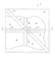
図1に示すように、上記特許に記載の光スイッチ15は、クラッド材料27によって包囲されたコア材料の導波路区画22〜25を備えている。導波路区画22及び23は、液体34が充填されたトレンチ32によって導波路区画24及び25から分離されている(図2)。液体34の屈折率は、導波路区画22〜24の屈折率に近いか、または、同じである。従って、光スイッチ15の第1の状態において、導波路区画22を通過する光信号は、トレンチ32への到達時に、ほとんど反射または屈折を生じない。代わりに、導波路区画22からの光信号は、液体34を通過して、導波路区画24に入射する。
【0004】
トレンチ32には、光スイッチ15の状態を切換えるために利用可能な、基板上に配置された加熱素子35(図2)も含まれている。加熱素子35には、加熱素子35によって発生する熱量を選択的に増/減するための制御回路要素が含まれている。光スイッチ15の状態を切換えるため、加熱素子35の温度が液体34の沸点を超えるまで、加熱素子35の温度を上昇させることによって、図3に示すように、液体34内に気泡41が形成させられる。気泡41は、液体34及び導波路区画22〜25とは屈折率が大きく異なり、導波路区画22から導波路区画24まで延びている。従って、導波路区画22を通過する光信号は、導波路区画22と気泡41の界面において反射される。従って、導波路区画22によって伝送される光信号は、導波路区画22と気泡41の界面において反射され、導波路区画24ではなく、導波路区画23に沿って進行する。
【0005】
光スイッチ15をもとの状態に戻すため、気泡41が崩壊するまで、加熱素子35の温度が低下させられる。換言すれば、加熱素子35の温度は、液体34の沸点またはそれ未満にまで低下させられる。気泡41が崩壊すると、導波路区画22に沿って進行する光信号は、もはや、導波路区画22の端部において反射されず、光信号は、従って、導波路区画23ではなく、導波路区画24に送り込まれる。
【0006】
しかし、気泡42(図4)が偶然トレンチ32内に形成されると、光スイッチ15に関する問題が生じる。こうした条件下では、加熱素子35が液体34の沸点未満であっても、気泡42が期せずしてトレンチ32内に形成されることがある。こうした状態になると、導波路区画22に沿って進行する信号は、加熱素子35の温度に関係なく導波路区画23に向かって反射される。
【0007】
【発明が解決しようとする課題】
従って、本発明の目的は、光スイッチにおける気泡の形成を制御して、不慮の気泡がトレンチ内に形成されて、光スイッチの働きを妨げることがないようにする方法と、そのように動作する装置を提供することにある。
【0008】
【課題を解決するための手段】
本発明によれば、上述の先行技術に関する不足及び欠点が克服される。一般に、本発明によれば、光スイッチにおける気泡の偶発的な形成を防止するための装置及び方法が得られる。
【0009】
本発明には、基板、第1の導波路区画、第2の導波路区画、加熱素子、液体、及び、圧力制御機構が含まれている。基板は、第1の導波路区画及び第2の導波路区画に結合され、第1の導波路区画を第2の導波路区画から分離する房を含んでいる。液体は、房内に納められており、加熱素子に反応する。圧力制御機構によって、房内の圧力が制御され、第1の導波路区画と第2の導波路区画間における不測の気泡形成が阻止される。
【0010】
本発明のもう1つの特徴によれば、房は、第1の隔室(コンパートメント)と第2の隔室から構成される。2つの隔室は、第1の隔室から第2の隔室に延びる通路を介して相互接続されている。房内の圧力を制御するため、圧力制御機構によって、第2の隔室内で液体の温度が制御される。
【0011】
本発明のもう1つの特徴によれば、圧力制御機構は、ピストンとアクチュエータから構成される。アクチュエータは、房内の圧力を高めるため、ピストンをある方向に移動させ、房内の圧力を低下させるため、ピストンを逆方向に移動させる。
【0012】
本発明のもう1つの特徴によれば、圧力制御機構は、ある物質を、房内に注入する、及び/又は、房から取り除くことによって、房内における圧力を制御する。
【0013】
本発明は、また、光信号を切換えるための方法を提供するものとみなすことも可能である。この方法には、第1の導波路、第2の導波路、及び、第3の導波路を設けるステップと、液体が充填された房を含んでおり、房によって、第1の導波路区画が第2の導波路区画から分離されるようになっている、基板を設けるステップと、加熱素子を設けるステップと、第1の導波路区画を介して光信号を伝送するステップと、第1の温度から第2の温度に加熱素子の温度を上昇させることによって、液体内に気泡を形成するステップと、房内の圧力を調整し、加熱素子の温度が第1の温度の場合には、第1の導波路区画を介して伝送される光信号が、房を通って、第2の導波路区画に送り込まれるようにし、加熱素子の温度が、第2の温度になると、第1の導波路区画を介して伝送される光信号が、前記気泡の境界において反射され、第3の導波路区画を介して伝送されるようにするステップが含まれている。
【0014】
本発明の他の特徴及び利点については、添付の図面と関連づけて読み取れば、下記の詳細な説明を検討することにより、当該技術者には明らかなになるであろう。こうした特徴及び利点は、全て、本発明に包含されるものとする。
【0015】
【発明の実施の形態】
発明者の発見によれば、従来の技術に関して上記し、図4に示すように、内面反射光スイッチ15のトレンチ内における偶発的な気泡42の形成は、通常、加熱素子35から基板38を介して拡散する熱によって誘発される。これに関して、基板38の温度は、加熱素子35が繰り返し熱を発生すると、次第に上昇する場合が多い。光スイッチ15が、同様のスイッチ・アレイの1つである場合、他の光スイッチに関連した近くの加熱素子によって発生する熱のために、基板38の温度が次第に上昇する可能性がある。
【0016】
結果として、基板38は、図4に示すように、トレンチ32内に不測の気泡42の形成を誘導するのに十分な高温になる可能性がある。換言すれば、さまざまな位置における基板38の温度が、液体34の沸点を超え、そのため、液体34内における不測の気泡42の形成を誘導することになる可能性がある。この気泡42によって、光スイッチ15は、加熱素子35の状態(すなわち、温度)に関係なく、反射状態になる。さらに、基板38の温度のために、導波路区画22によって伝送される光信号を反射するのに十分なサイズの不測の気泡42が誘発される限りにおいて、導波路区画22によって伝送される各信号は、導波路区画23に沿って反射され、加熱素子35の温度制御では、光スイッチ15の状態を制御するのに効果がない。
【0017】
一般に、本発明によれば、図1〜3に示す従来の光スイッチ15と同様の改良された光スイッチ50(図5)が得られる。しかし、従来の光スイッチ15とは異なり、本発明の光スイッチ50には、液体34に加えられる圧力を制御する圧力制御機構52(図6)が含まれている。圧力制御機構52によって、この圧力は十分な高さに保たれるので、基板38からの熱によって、液体内に不測の気泡形成が誘発されることはない。従って、光スイッチ50の切換特性は、基板38の温度によってあまり影響される異はない。
【0018】
図5及び図6を参照すると、光スイッチ50のクラッド材料27によって、導波路区画22〜25が結合される基板が形成される。クラッド材料27による基板には、導波路区画22及び23を、それぞれ、導波路区画24及び25から分離する房54が含まれている。房54は、液体34が充填されており、房54には気密密閉を施し、液体34には脱ガスを施すのが望ましいが、脱ガスが施されていない液体34を利用することも可能である。房54内には、加熱素子35が結合される基板38が配置されている。
【0019】
光スイッチ50の第1の状態において、加熱素子35の温度は、液体34の沸点以下の第1の温度である。従って、導波路区画22及び24間における液体内には、気泡は存在しない。液体34の屈折率は、光が液体に入射し、あまり方向を変化させずに、通過するように、導波路区画22〜25の屈折率に対して十分にうまく整合することが望ましい。従って、光スイッチ50の第1の状態において、導波路区画22を介して光スイッチ50に入力される光信号は、液体34を通過して、導波路区画24に入射する。
【0020】
光スイッチ50の第2の状態において、加熱素子35の温度は、液体34の沸点である第2の温度まで上昇する。この状態において、加熱素子35からの熱によって、図3に示すように、液体34内に気泡41が形成される。気泡41は、導波路区画22の端部から導波路区画24の端部まで延びるのが望ましい。従って、導波路区画22を介して光スイッチ50に入力される光信号は、導波路区画22と気泡41の界面において反射され、導波路区画23を介して光スイッチ50から出射する。
【0021】
図6に示すように、光スイッチ50には、房54内の圧力を制御する圧力制御機構が含まれている。圧力制御機構52によって、房54内の圧力は、不測の気泡形成を阻止する範囲内に維持されるが、光スイッチ50がその第2の状態にある場合、加熱素子35からの熱によって、房54内に気泡を形成することは可能である。
【0022】
これに関して、房54内の圧力が上昇するにつれて、液体34の沸点が上昇し、房54内の圧力が低下するにつれて、液体34の沸点が低下する。さらに、基板38の加熱は、主として、加熱素子35を第2の温度まで加熱するか、または、近くの同様の加熱素子を第2の温度まで加熱することによって生じるので、基板38の温度は、一貫して、上述の第2の温度より低いことが望ましい。
【0023】
液体34の沸点は、房54の圧力とともに変化し、基板38の温度は、一貫して第2の温度より低いことが望ましいので、液体34の沸点を基板38の温度と第2の温度との間の範囲内の温度にする、房54内における圧力範囲が存在する。房54内の圧力がこの圧力範囲内に維持される限りにおいて、その圧力によって、基板38からの熱が、液体34内において偶発的な気泡42の形成を誘発するのが阻止され、加熱素子35からの熱だけに反応して、液体34内に気泡41を形成することが可能になる。
【0024】
しかし、房54内の圧力が、この上述の圧力範囲の最低値未満になると、基板38からの熱によって、液体34内に不測の気泡42が形成される可能性がある。この結果、スイッチ50が図らずも反射状態(すなわち、第2の状態)になる。房54内の圧力が、この上述の圧力範囲より高くなると、加熱素子35の温度が第2の温度である場合、加熱素子35からの熱では、液体34内に気泡の形成を誘発するのに不十分である。従って、光スイッチ50が、加熱素子35だけに応答して機能することを保証するため、圧力制御機構52によって、房54内の圧力が上述の圧力範囲内に維持される。
【0025】
さまざまな方法及び装置を用いて、房54内の圧力を制御することが可能である。望ましい実施例の場合、房54内の圧力は、液体34の一部の温度を制御することによって制御される。図5及び図6によって示されるように、望ましい実施例の房54は、2つの隔室55及び58と、通路62から構成される。通路62は、隔室55から隔室58まで延びており、隔室55及び58のいずれか一方からの液体34が、通路62を通って、隔室55及び58のもう一方に流入することが可能である。
【0026】
図6によって示される構成の場合、圧力制御機構52には、熱を発生して、隔室58内における液体34の温度を制御する加熱素子が含まれている。隔室58は、一部が液体34によって、また、一部が、蒸気によって充填されており、液体34は蒸気と平衡がとれている。当該技術において既知のように、密閉された房内における液相/気相の2相系の圧力は、温度に比例して変動する。従って、圧力制御機構52は、隔室58内の温度を制御することによって、房54全体の圧力を制御する。
【0027】
圧力制御機構52が、隔室58内の液体34の温度に作用して、房54内における適正な温度範囲を維持することができるのが望ましいが、一般には、圧力制御機構52によって、隔室55内における液体34の温度がかなりの影響を受けるのは望ましくない。これに関して、液体34の温度を変化させると、液体34の屈折率が影響される。導波路区画22〜25からの光信号は、隔室55内の液体を通過するので、光信号の減衰を最小限に抑えるには、隔室55内の液体34の屈折率は一定であることが望ましい。従って、隔室55内における液体34の温度は、隔室55内における液体34の屈折率の変動を最小限に抑えるため、一定に保たれるべきである。
【0028】
図6に示されるように、液体34を2つの隔室55及び58内に分離するのは、隔室55内における液体34の温度を一定に保つのに役立つ。これに関して、通路62の比較的小さい断面積によって、2つの隔室55及び58の液体34間における熱伝達が妨げられる。しかし、通路62によって、隔室58内の圧力は房全体に通じている。従って、隔室58内における液体34の温度が変化しても、隔室55内における液体34の温度にはあまり影響がないが、房54全体の圧力は急速に変化する。従って、房54を2つの隔室55及び58に分割することは、圧力制御機構52の房54全体の圧力を決定する能力をあまり損なうことなく、隔室55内の液体34を一定の温度に維持するのに役立つことになる。
【0029】
留意すべきは、液体34の温度が隔室58の温度変化によって受ける影響は、通路62の断面積をより小さくすると、低下するという点である。従って、通路62の断面積は、2つの隔室55及び58間における圧力変化の伝達能力と両立、できるだけ小さいことが望ましい。
【0030】
図7は、スイッチ50の動作方法を示すフローチャートである。動作時、図7のブロック65及び67によって示されるように,スイッチ50をモニタすることが可能で、加熱素子35の温度が、液体34の沸点未満が望ましい第1の温度でありえる。これに関して、図7のブロック69及び71によって示されるように、導波路区画22を介したスイッチ50に対する光信号の入力が、導波路区画24と導波路区画23のいずれを介して出力されるかの決定がなされる。信号が、導波路区画24を介して出力される場合、房54内の圧力は十分に高く、隔室58内における液体34の温度を上昇させる必要がない。従って、圧力制御機構52は、図7のブロック73によって示されるように、隔室58内の液体34の温度を維持することによって、房54内の圧力を維持する。しかし、光信号が導波路区画23を介して出力される場合、液体34内に、不測の気泡42が形成されていることがある。この場合、図7のブロック74によって示されるように、房54内の圧力を上昇させて、不測の気泡42を崩壊させることが望ましい。
【0031】
ブロック69、71、及び、74を実施する場合、導波路区画22を介して光スイッチ50に入力される光信号が、導波路区画24を介して出力されるまで、圧力制御機構52によって発生する熱が上昇させられる。圧力制御機構52からの熱によって、隔室58内の液体34の温度が上昇するにつれて、房54内の圧力が高まり、不測の気泡42のサイズが収縮する。導波路区画22を介して入力される光信号が、導波路区画24を介して出力されると、基板38からの熱では、光スイッチ50の動作にかなりの影響を与えるのは不十分になり、さらに、隔室58の温度を上昇させる必要がなくなる。従って、図7のブロック73によって示されるように、圧力制御機構52は、隔室55内の圧力を維持するため、必要に応じて、隔室58内の液体34に対する加熱を続行する。
【0032】
図7のブロック77によって示されるように、加熱素子35の温度が、液体34の沸点を超えることが望ましい第2の温度である場合には、光スイッチ50のモニタも実施される。加熱素子35の温度が、第2の温度である場合、加熱素子35によって生じる熱のために、房54内に気泡41が形成されるはずである。従って、導波路区画22を介して入力される光信号は、気泡41と導波路区画22の端部との界面において反射されるはずであり、従って、光信号は、導波路区画23を介して出力されるはずである。光信号が、実際に、導波路区画23を介して出力される場合、房54内の圧力は、加熱素子35による気泡41の発生を可能にするのに十分な程に低い。従って、圧力制御機構52は、図7のブロック73、78、及び、79によって示されるように、隔室58内の液体34の温度を維持することによって、房54内の圧力を維持する。しかし、光信号が、代わりに、導波路区画24を介して出力される場合、房54内の圧力が、高すぎるため、加熱素子35によって生じる熱に応答して気泡41を形成することができない。従って、図7のブロック78、79、及び、80によって示されるように、光信号が、導波路区画24を介してスイッチ50から出力されるまで、隔室58の温度は、圧力制御機構52によって低下させられる。
【0033】
ブロック78、79、及び、80を実施する場合、導波路区画22を介して光スイッチ50に入力される光信号が、導波路区画24を介してもはや出力されなくまるまで、圧力制御機構52によって生じる熱が低下させられる。圧力制御機構52からの熱の低下によって、隔室58内の液体34の温度が低下するにつれて、房54内の圧力も低下し、加熱素子35からの熱によって誘発される気泡のサイズが拡張する。ブロック79において、導波路区画22を介して入力される光信号が、導波路区画24を介してもはや出力されていないということになると、房54内の圧力は、気泡41の形成を可能にするのに十分なほど低く、隔室58内の液体34の温度をそれ以上低下させる必要がなくなる。従って、図7のブロック73によって示されるように、圧力制御機構52は、隔室58内における液体34の温度を維持するため、必要に応じて、隔室58内の液体34に対する加熱を続行する。
【0034】
上記モニタ及び制御を実施することによって、房54内の圧力が適正な圧力範囲内に維持されるという保証が得られる。所望に応じて、モニタ及び制御を繰り返すことによって、スイッチ50が、加熱素子35だけに応答して、動作し続けるという保証を得ることが可能になる。
【0035】
圧力制御機構52の動作を制御するため、圧力制御機構52には、図8によって示されるように、コントローラ85を含むのが望ましい。望ましい実施例の場合、コントローラ85は、電気回路要素及び/または機械コンポーネントを含むハードウェアによって実施されるが、所望であれば、ソフトウェアまたはハードウェアとソフトウェアの組み合わせによって実施することも可能である。コントローラ85は、データ・インターフェイス86から、導波路区画22を介して光スイッチ50に入力される信号を出力するのが、導波路区画23と24のどちらであるかを指示する通知信号を受信する。望ましい実施例の場合、データ・インターフェイス86には、通知信号を自動的に発生して、コントローラ85に伝送することができるように、光が導波路区画23及び24のいずれを通って進行しているかを検出するセンサが含まれている。
【0036】
コントローラ85は、図7のブロック74及び80において、上述の通知信号に基づき、圧力制御機構52によって発生する熱を上昇させるべきか、あるいは、低下させるべきかの判定を行い、圧力制御機構52によって発生する熱を制御するための制御信号を加熱素子87に送る。一例として、加熱素子87は、抵抗器とすることが可能である。コントローラ85は、圧力制御機構52によって発生する熱量を増大させるため、加熱素子87に印加する電圧を高くし、圧力制御機構52によって発生する熱量を減少させるため、加熱素子87に印加する電圧を低くする。代わりに、コントローラ85は、加熱素子87に伝送される加熱パルスのデューティ・サイクルを変更するといった、他の技法によって加熱素子87を制御することも可能である。コントローラ85は、さらに、図7のブロック73において、それが房54内の圧力を維持するのを助けるため、房54内に配置された温度センサ88及び/または圧力センサ89から入力を受信することが可能である。
【0037】
望ましい実施例には、2つの隔室55及び58を備えた房54が含まれているが、留意すべきは、任意の数の(1つ以上の)隔室を利用して、本発明を実施することが可能であるという点である。例えば、圧力制御機構52は、所望の場合、隔室55内の液体34を直接加熱することが可能であり、隔室58及び通路62は不要になる。しかし、前述のように、一般には、隔室55内の液体34の温度に対する影響は最小限にするのが望ましく、従って、望ましい実施例に基づいて隔室58内の液体34を加熱するのが望ましい。
【0038】
さらに、房54内の液体34を加熱する以外の技法を用いて、房54内の圧力を制御することも可能である。例えば、図9には、圧力制御機構52がピストン81とアクチュエータ84から構成された実施例が示されている。アクチュエータ84は、房54内の圧力を高めるために、ピストンをy方向に移動させ、房54内の圧力を下げるため、ピストン81を逆方向に移動させる。図9によって示された実施例の働きは、房54内の圧力が、流体34の温度を変化させる代わりに、ピストン81を移動させることによって制御されるという点を除けば、図6によって示された実施例の働きと同じである。
【0039】
図10によって示されるように、アクチュエータ84は、房54内の圧力を増/減させるため、いつ、どの方向にピストン81を移動させるべきかを判定する、コントローラ90に結合されるのが望ましい。コントローラ85(図8)と同様に、コントローラ90も、データ・インターフェイス及び/または圧力センサ89から入力を受信して、房54内の圧力を高める必要があるか、または、低下させる必要があるかの判定を行うことが可能である。さらに、コントローラ90は、電気回路要素及び/または機械コンポーネントを含むハードウェアによって実施するのが望ましいが、所望であれば、ソフトウェアまたはハードウェアとソフトウェアの組み合わせによって実施することも可能である。
【0040】
図11によって示されるもう1つの実施例の場合、圧力制御機構52は、液体または蒸気のような物質を密閉房54内に注入することによって、房54内の圧力を高めるインジェクタ91から構成することが可能である。解放弁94を用いて、房54内の液体34または蒸気の一部が脱出して、リザーバ97に流入できるようにすることによって、房54内の圧力を低下させることが可能である。図11によって示される実施例の働きは、房54内の圧力が、それぞれ、房54内にある物質を注入し、房54内からその物質を放出することによって制御されるという点を除けば、図6によって示された実施例の働きと同じである。
【0041】
図12によって示されるように、上述の実施例の圧力制御機構52には、インジェクタ91の及び解放弁94の動作を制御し、インジェクタ91を介して、房54内にある物質を注入すべき時機、または、解放弁94を介して、房54内からその物質を解放すべき時機を判定するためのコントローラ99が含まれているのが望ましい。コントローラ85(図8)と同様、コントローラ99は、データ・インターフェイス86及び/または圧力センサ89から入力を受信して、房54内の圧力を高める必要があるか、または、低下させる必要があるかの判定を行うことが可能である。さらに、コントローラ99は、電気回路要素及び/または機械コンポーネントを含むハードウェアによって実施するのが望ましいが、所望であれば、ソフトウェアまたはハードウェアとソフトウェアの組み合わせによって実施することも可能である。
【0042】
留意すべきは、とりわけ、スイッチ50が交換網に用いられている場合、同じ房54及び圧力制御機構52を利用する、複数のスイッチ50を設計することが可能であるという点である。従って、複数の加熱素子35が房54内に存在する可能性がある。この状況の場合、他の加熱素子による気泡の形成が、房54内の圧力に影響する、従って、スイッチ50の切換特性に影響する可能性がある。しかし、上述のように、房54の圧力をモニタして、適正な範囲内に維持することによって、圧力制御機構52は、他の加熱素子及び/または基板に関連した気泡の形成によって誘発される追加圧力を補償する。
【0043】
上述の実施例の場合、液体34内における気泡41または42の存在が、導波路区画22を介して入力される光信号が、導波路区画23と24のどちらを介して出力されるかを確かめることによって検出される。しかし、他の方法を利用して、気泡41または42の存在を検出することもできるし、液体34内における気泡41または42の存在を検出するための任意の技法を用いて、本発明を実施することも可能である。
【0044】
強調しておくべきは、本発明の上述の実施例、すなわち、どの「望ましい」実施例も、本発明について可能性のある単なる実施例にすぎない。上述の実施例に対して、多くの変更及び修正を施すことが可能である。従って、こうした修正及び変更は、全て、本発明の範囲内に含まれるものとする。
以下に本発明の広汎な応用のための実施態様の数例をかかげる。
【0045】
(実施態様1)
光スイッチ(50)であって、
第1の導波路区画(22)と、
第2の導波路区画(24)と、
房(54)を形成し、前記第1と第2の導波路区画(22、24)に結合されており、前記房(54)によって、前記第1の導波路区画(22)を前記第2の導波路区画(24)から分離するようになっている、基板(27)と、
前記房(54)内において前記導波路区画(22、24)の交差点に配置されている加熱素子(35)と、
前記房(54)内に配置されて、前記加熱素子(35)に反応する液体(34)と、
前記房(54)内の圧力を制御するための手段(52)が含まれている、
光スイッチ(50)。
【0046】
(実施態様2)
前記制御手段(52)に、ピストン(81)が含まれていることを特徴とする、実施態様1に記載の光スイッチ(50)。
(実施態様3)
前記制御手段(52)に、インジェクタ(91)が含まれていることを特徴とする、実施態様1に記載の光スイッチ(50)。
【0047】
(実施態様4)
前記加熱素子(35)が、第1の状態において第1の温度を有し、第2の状態において第2の温度を有することと、前記制御手段(52)によって、前記液体(34)の沸点を前記第1の温度と前記第2の温度の間の温度に設定する圧力範囲内に前記圧力が維持されることを特徴とする、実施態様1に記載の光スイッチ(50)。
【0048】
(実施態様5)
前記制御手段(52)に加熱素子(87)が含まれることを特徴とする、実施態様1に記載の光スイッチ(50)。
【0049】
(実施態様6)
前記房(54)に、間に通路(62)を備えた第1の隔室(55)と第2の隔室(58)が含まれていることと、前記加熱素子(87)によって、前記第2の隔室(58)内の前記液体(34)が加熱されると、前記圧力が上昇することを特徴とする、実施態様5に記載の光スイッチ(50)。
【0050】
(実施態様7)
光信号を切換えるための方法であって、
第1の導波路区画(22)、第2の導波路区画(24)、及び、第3の導波路区画(23)を設けるステップと、
液体(34)が充填された房(54)を含んでおり、前記房(54)によって、前記第1の導波路区画(22)が前記第2の導波路区画(24)から分離されるようになっている、基板(27)を設けるステップと、
加熱素子(35)を設けるステップと、
前記第1の導波路区画を介して光信号を伝送するステップと、
前記房(54)内の圧力を調整し、前記加熱素子(35)の温度が第1の温度の場合には、前記第1の導波路区画(22)を介して伝送される光信号が、前記房(54)を通って、前記第2の導波路区画(24)に送り込まれるようにし、前記加熱素子(35)の前記温度が、上昇して、第2の温度を超える場合に限って、前記液体(34)内に気泡(41)が形成され、前記第1の導波路区画(22)を介して伝送される光信号が反射されて、前記第3の導波路区画(23)内に送り込まれるようにするステップが含まれている、
切換方法。
【0051】
(実施態様8)前記調整ステップに、ある物質を前記房(54)内に注入するステップが含まれることを特徴とする、実施態様7に記載の方法。
【0052】
(実施態様9)
さらに、ピストン(81)を設けるステップが含まれることと、前記調整ステップに、前記ピストン(81)を移動させるステップが含まれることを特徴とする、実施態様7に記載の方法。
【0053】
(実施態様10)
前記調整ステップに、前記液体(34)を加熱するステップが含まれることを特徴とする、実施態様7に記載の方法。
【図面の簡単な説明】
【図1】従来の光スイッチの平面図である。
【図2】図1によって示されたスイッチの断面図である。
【図3】少なくとも2つの導波路区画を分離する液体内に、気泡が適正に形成された場合の、図2のスイッチを表した断面図である。
【図4】少なくとも2つの導波路区画を分離する液体内に、気泡が偶発的に形成された場合の、図2のスイッチを表した断面図である。
【図5】本発明の光スイッチの平面図である。
【図6】図5によって示されたスイッチの断面図である。
【図7】図6の圧力制御機構の構成及び機能性を表したフローチャートである。
【図8】図6の圧力制御機構を例示したブロック図である。
【図9】圧力制御機構がアクチュエータとピストンから構成される場合の、図6のスイッチを表した断面図である。
【図10】図9の圧力制御機構を例示したブロック図である。
【図11】圧力制御機構にインジェクタが含まれる場合の、図6の房及び圧力制御機構を表した側面図である。
【図12】図11の圧力制御機構を例示したブロック図である。
【符号の説明】
22 第1の導波路区画
23 第3の導波路区画
24 第2の導波路区画
27 基板
34 液体
35 加熱素子
41 気泡
50 光スイッチ
52 圧力制御手段
54 房
55 第1の隔室
58 第2の隔室
62 通路
81 ピストン
87 加熱素子
91 インジェクタ[0001]
BACKGROUND OF THE INVENTION
The present invention relates generally to optical switches, and more particularly to an optical switch based on total reflection that controls fluid pressure within the optical switch to improve switching characteristics.
[0002]
[Prior art]
Some internally reflected light switches change state by forming bubbles in the liquid placed at the intersection of the respective waveguide sections. For example, see US Pat. No. 5,699,462 (corresponding Japanese Patent Application Laid-Open No. 10-90735: “Optical Switch Element and Optical Switch Method”) entitled “Total Internal Reflection Optical Switches Employing Thermal Activation” incorporated by reference. ) Describes an optical switch that changes the state using bubbles.
[0003]
As shown in FIG. 1, the
[0004]
The
[0005]
In order to return the
[0006]
However, if bubbles 42 (FIG. 4) are accidentally formed in
[0007]
[Problems to be solved by the invention]
Accordingly, it is an object of the present invention and a method to control the formation of bubbles in an optical switch so that inadvertent bubbles are not formed in the trench and interfere with the operation of the optical switch, and operate as such. To provide an apparatus.
[0008]
[Means for Solving the Problems]
The present invention overcomes the deficiencies and drawbacks associated with the prior art described above. In general, the present invention provides an apparatus and method for preventing accidental formation of bubbles in an optical switch.
[0009]
The present invention includes a substrate, a first waveguide section, a second waveguide section, a heating element, a liquid, and a pressure control mechanism. The substrate includes a tuft coupled to the first waveguide section and the second waveguide section and separating the first waveguide section from the second waveguide section. The liquid is contained in the chamber and reacts to the heating element. The pressure control mechanism controls the pressure in the chamber and prevents inadvertent bubble formation between the first waveguide section and the second waveguide section.
[0010]
According to another characteristic of the invention, the tuft is composed of a first compartment (compartment) and a second compartment. The two compartments are interconnected via a passage extending from the first compartment to the second compartment. In order to control the pressure in the chamber, the temperature of the liquid is controlled in the second compartment by a pressure control mechanism.
[0011]
According to another feature of the invention, the pressure control mechanism comprises a piston and an actuator. The actuator moves the piston in a certain direction to increase the pressure in the chamber, and moves the piston in the opposite direction to decrease the pressure in the chamber.
[0012]
According to another feature of the invention, the pressure control mechanism comprises: A substance The , Bunch Inside In Inject and / or Remove from cell Kuko To control the pressure in the chamber.
[0013]
The present invention can also be viewed as providing a method for switching optical signals. The method includes providing a first waveguide, a second waveguide, and a third waveguide, and a tuft filled with liquid, whereby the tuft has a first waveguide section. Providing a substrate, providing a heating element, transmitting an optical signal through the first waveguide section, and being configured to be separated from the second waveguide section; and a first temperature. The step of forming bubbles in the liquid by adjusting the temperature of the heating element from the first temperature to the second temperature and the pressure in the chamber are adjusted, and when the temperature of the heating element is the first temperature, the first temperature When the optical signal transmitted through the waveguide section is sent to the second waveguide section through the tuft, and the temperature of the heating element reaches the second temperature, the first waveguide section And the optical signal transmitted through the bubble is reflected at the bubble boundary, It includes the step of to be transmitted through the waveguide section.
[0014]
Other features and advantages of the present invention will become apparent to those skilled in the art upon review of the following detailed description when read in conjunction with the accompanying drawings. All of these features and advantages are intended to be encompassed by the present invention.
[0015]
DETAILED DESCRIPTION OF THE INVENTION
According to the inventor's discovery, as described above with respect to the prior art and shown in FIG. 4, the formation of incidental bubbles 42 in the trench of the
[0016]
As a result, the
[0017]
In general, the present invention provides an improved optical switch 50 (FIG. 5) similar to the conventional
[0018]
Referring to FIGS. 5 and 6, the
[0019]
In the first state of the
[0020]
In the second state of the
[0021]
As shown in FIG. 6, the
[0022]
In this regard, the boiling point of the liquid 34 increases as the pressure in the
[0023]
Since the boiling point of the liquid 34 changes with the pressure in the
[0024]
However, if the pressure in the
[0025]
A variety of methods and devices can be used to control the pressure within the
[0026]
In the configuration illustrated by FIG. 6, the
[0027]
While it is desirable for the
[0028]
As shown in FIG. 6, separating the liquid 34 into the two
[0029]
It should be noted that the effect of the temperature of the liquid 34 due to the temperature change of the
[0030]
FIG. 7 is a flowchart showing an operation method of the
[0031]
When implementing blocks 69, 71, and 74, an optical signal that is input to the
[0032]
If the temperature of the
[0033]
When implementing blocks 78, 79, and 80, the
[0034]
By performing the above monitoring and control, a guarantee that the pressure in the
[0035]
In order to control the operation of the
[0036]
The
[0037]
Although the preferred embodiment includes a
[0038]
Furthermore, it is possible to control the pressure in the
[0039]
As shown by FIG. 10, the
[0040]
In another embodiment, illustrated by FIG. 11, the
[0041]
As shown by FIG. 12, the
[0042]
It should be noted that it is possible to design
[0043]
In the case of the embodiment described above, the presence of
[0044]
It should be emphasized that the above-described embodiments of the present invention, ie any “desirable” embodiment, is merely a possible embodiment of the present invention. Many changes and modifications can be made to the embodiments described above. Accordingly, all such modifications and changes are intended to be included within the scope of the present invention.
The following are some examples of embodiments for the broad application of the present invention.
[0045]
(Embodiment 1)
An optical switch (50),
A first waveguide section (22);
A second waveguide section (24);
A tuft (54) is formed and coupled to the first and second waveguide sections (22, 24), and the tuft (54) connects the first waveguide section (22) to the second. A substrate (27) adapted to be separated from the waveguide section (24) of
A heating element (35) arranged at the intersection of the waveguide sections (22, 24) in the tuft (54);
A liquid (34) disposed in the tuft (54) and responsive to the heating element (35);
Means (52) for controlling the pressure in the tuft (54) are included,
Optical switch (50).
[0046]
(Embodiment 2)
The optical switch (50) according to embodiment 1, characterized in that the control means (52) includes a piston (81).
(Embodiment 3)
The optical switch (50) according to embodiment 1, characterized in that the control means (52) includes an injector (91).
[0047]
(Embodiment 4)
The heating element (35) has a first temperature in the first state and a second temperature in the second state, and the boiling point of the liquid (34) by the control means (52). 2. The optical switch (50) according to embodiment 1, characterized in that the pressure is maintained within a pressure range that sets the temperature to a temperature between the first temperature and the second temperature.
[0048]
(Embodiment 5)
The optical switch (50) according to embodiment 1, characterized in that the control means (52) includes a heating element (87).
[0049]
(Embodiment 6)
The tuft (54) includes a first compartment (55) and a second compartment (58) with a passageway (62) therebetween, and the heating element (87) The optical switch (50) according to embodiment 5, characterized in that the pressure increases when the liquid (34) in the second compartment (58) is heated.
[0050]
(Embodiment 7)
A method for switching an optical signal,
Providing a first waveguide section (22), a second waveguide section (24), and a third waveguide section (23);
A tuft (54) filled with a liquid (34), wherein the tuft (54) separates the first waveguide section (22) from the second waveguide section (24). Providing a substrate (27),
Providing a heating element (35);
Transmitting an optical signal through the first waveguide section;
When the pressure in the tuft (54) is adjusted and the temperature of the heating element (35) is a first temperature, the optical signal transmitted through the first waveguide section (22) is Only when the temperature of the heating element (35) rises and exceeds the second temperature, through the tuft (54) and into the second waveguide section (24). A bubble (41) is formed in the liquid (34), and an optical signal transmitted through the first waveguide section (22) is reflected, so that the inside of the third waveguide section (23) is reflected. Includes steps to be sent to the
Switching method.
[0051]
(Embodiment 8) In the adjustment step, A substance The bunch (54) Inside In inject Embodiment 8. The method according to embodiment 7, characterized in that steps are included.
[0052]
(Embodiment 9)
8. The method of embodiment 7, further comprising the step of providing a piston (81) and the adjusting step includes the step of moving the piston (81).
[0053]
(Embodiment 10)
Embodiment 8. The method of embodiment 7, wherein the conditioning step includes heating the liquid (34).
[Brief description of the drawings]
FIG. 1 is a plan view of a conventional optical switch.
FIG. 2 is a cross-sectional view of the switch shown by FIG.
FIG. 3 is a cross-sectional view of the switch of FIG. 2 when bubbles are properly formed in the liquid separating at least two waveguide sections.
4 is a cross-sectional view of the switch of FIG. 2 when bubbles are accidentally formed in the liquid separating at least two waveguide sections.
FIG. 5 is a plan view of the optical switch of the present invention.
6 is a cross-sectional view of the switch illustrated by FIG.
7 is a flowchart showing the configuration and functionality of the pressure control mechanism of FIG. 6;
FIG. 8 is a block diagram illustrating the pressure control mechanism of FIG. 6;
9 is a cross-sectional view showing the switch of FIG. 6 when the pressure control mechanism includes an actuator and a piston.
10 is a block diagram illustrating the pressure control mechanism of FIG. 9;
11 is a side view showing the tuft and the pressure control mechanism of FIG. 6 when the pressure control mechanism includes an injector. FIG.
12 is a block diagram illustrating the pressure control mechanism of FIG. 11. FIG.
[Explanation of symbols]
22 First waveguide section
23 Third waveguide section
24 Second waveguide section
27 Substrate
34 Liquid
35 Heating element
41 bubbles
50 Optical switch
52 Pressure control means
54 bunch
55 First compartment
58 Second compartment
62 passage
81 piston
87 Heating element
91 Injector
Claims (12)
第1の導波路区画と、
第2の導波路区画と、
房を画定する基板であって、該基板は、前記第1及び第2の導波路区画に結合されており、前記房は、前記第1の導波路区画を前記第2の導波路区画から分離させていることからなる、基板と、
前記房内において前記導波路区画の交差点に配置された第1の加熱素子と、
前記房内に配置された液体であって、前記第1の加熱素子により加熱される、液体と、
前記房内の圧力を所定範囲内に維持するよう制御するための手段
とを備え、
前記制御するための手段が前記圧力を所定範囲内に維持するよう制御することが、それにより、前記第1の加熱素子の温度が第1の温度の時には、前記第1の導波路区画を介して伝達された光信号が、前記房を通過して、前記第2の導波路区画内へと送り込まれることとなるようにし、及び、前記第1の加熱素子の前記温度が、第2の温度を超えるように上昇した時に限っては、前記液体内に気泡が形成されて、前記第1の導波路区画を介して伝達された光信号が該気泡により反射させられることとなるようにすることを含み、
前記制御するための手段が、第2の加熱素子を含み、
前記房が、第1の隔室と第2の隔室とを備え、該第1の隔室と該第2の隔室との間に通路を有し、及び、
前記第2の加熱素子が、前記第2の隔室内の前記液体を加熱させて、前記圧力を上昇させることからなる、光スイッチ。An optical switch,
A first waveguide section;
A second waveguide section;
A substrate defining a tuft, the substrate being coupled to the first and second waveguide sections, wherein the tuft separates the first waveguide section from the second waveguide section. A substrate consisting of
A first heating element disposed at an intersection of the waveguide sections in the chamber;
A liquid disposed in the chamber, the liquid being heated by the first heating element;
Means for controlling to maintain the pressure in the chamber within a predetermined range,
The controlling means controls to maintain the pressure within a predetermined range such that when the temperature of the first heating element is a first temperature, the first waveguide element is routed through the first waveguide section. The transmitted optical signal passes through the tuft and is fed into the second waveguide section, and the temperature of the first heating element is a second temperature. Only when rising to exceed, bubbles are formed in the liquid so that the optical signal transmitted through the first waveguide section is reflected by the bubbles. Including
The means for controlling includes a second heating element;
The tuft includes a first compartment and a second compartment, the passage having a passage between the first compartment and the second compartment; and
The optical switch, wherein the second heating element heats the liquid in the second compartment and raises the pressure.
第2の導波路区画と、
圧力制御機構と、
房を備えた基板であって、該基板は、前記圧力制御機構と、前記第1の導波路区画と、前記第2の導波路区画とに結合されており、前記房は、前記第1の導波路区画を前記第2の導波路区画から分離させており、前記圧力制御機構によって、前記房内の圧力が所定範囲内に維持されるよう制御されることからなる、基板と、
前記房内において前記導波路区画の交差点に配置された第1の加熱素子と、
前記房内に配置された液体であって、前記第1の加熱素子により加熱される、液体
とを備え、
前記圧力制御機構が前記圧力を所定範囲内に維持するよう制御することが、それにより、前記第1の加熱素子の温度が第1の温度の時には、前記第1の導波路区画を介して伝達された光信号が、前記房を通過して、前記第2の導波路区画内へと送り込まれることとなるようにし、及び、前記第1の加熱素子の前記温度が、第2の温度を超えるように上昇した時に限っては、前記液体内に気泡が形成されて、前記第1の導波路区画を介して伝達された光信号が該気泡により反射させられることとなるようにすることを含み、
前記圧力制御機構が、第2の加熱素子を備え、
前記房が、第1の隔室と第2の隔室とによって画定され、該第1の隔室と該第2の隔室との間に通路を有し、及び、
前記第2の加熱素子が、前記第2の隔室内の前記液体を加熱させて、前記圧力を上昇させることからなる、光スイッチ。A first waveguide section;
A second waveguide section;
A pressure control mechanism;
A substrate comprising a tuft, wherein the substrate is coupled to the pressure control mechanism, the first waveguide section, and the second waveguide section, the tuft comprising the first A substrate that separates a waveguide section from the second waveguide section and is controlled by the pressure control mechanism to maintain the pressure in the chamber within a predetermined range; and
A first heating element disposed at an intersection of the waveguide sections in the chamber;
A liquid disposed in the chamber, the liquid being heated by the first heating element,
The pressure control mechanism controls to maintain the pressure within a predetermined range, so that when the temperature of the first heating element is the first temperature, the pressure is transmitted through the first waveguide section. The transmitted optical signal passes through the tuft and is fed into the second waveguide section, and the temperature of the first heating element exceeds a second temperature. Only when the bubble rises in such a manner that a bubble is formed in the liquid, and the optical signal transmitted through the first waveguide section is reflected by the bubble. ,
The pressure control mechanism includes a second heating element;
The tuft is defined by a first compartment and a second compartment, and has a passage between the first compartment and the second compartment; and
The optical switch, wherein the second heating element heats the liquid in the second compartment and raises the pressure.
前記圧力制御機構が、前記通知信号に基づいて前記圧力を所定範囲内に維持するよう調整することからなる、請求項5に記載の光スイッチ。The pressure control mechanism receives a notification signal indicating that an optical signal transmitted by the first waveguide section is received by the second waveguide section; and
The optical switch according to claim 5 , wherein the pressure control mechanism adjusts to maintain the pressure within a predetermined range based on the notification signal.
第1の導波路区画、第2の導波路区画、及び第3の導波路区画を提供し、
基板を提供し、前記基板は、液体によって満たされた房を備え、前記房は、前記第1の導波路区画を前記第2の導波路区画から分離させており、
加熱素子を提供し、
前記第1の導波路区画を介して光信号を伝達し、及び、
前記房内の圧力を所定範囲内に維持するよう調整し、それにより、前記加熱素子の温度が第1の温度の時には、前記第1の導波路区画を介して伝達された光信号が、前記房を通過して、前記第2の導波路区画内へと送り込まれることとなるようにし、及び、前記加熱素子の前記温度が、第2の温度を超えるように上昇した時に限っては、前記液体内に気泡が形成されて、前記第1の導波路区画を介して伝達された光信号が該気泡により反射させられて、前記第3の導波路区画内へと送り込まれることとなるようにする
ことを含み、
前記房が、第1の隔室と第2の隔室とによって画定され、該第1の隔室と該第2の隔室との間に通路を有し、及び、
前記調整することが、前記第2の隔室内の前記液体を加熱することを含むことからなる、方法。A method for switching optical signals,
Providing a first waveguide section, a second waveguide section, and a third waveguide section;
Providing a substrate, the substrate comprising a tuft filled with liquid, the tuft separating the first waveguide section from the second waveguide section;
Providing a heating element,
Transmitting an optical signal through the first waveguide section; and
The pressure in the chamber is adjusted to be maintained within a predetermined range, so that when the temperature of the heating element is the first temperature, the optical signal transmitted through the first waveguide section is Only when it passes through the tuft and is fed into the second waveguide section and when the temperature of the heating element rises above a second temperature. Bubbles are formed in the liquid so that the optical signal transmitted through the first waveguide section is reflected by the bubbles and sent into the third waveguide section. Including
The tuft is defined by a first compartment and a second compartment, and has a passage between the first compartment and the second compartment; and
The method wherein the conditioning comprises heating the liquid in the second compartment.
前記調整することが、前記ピストンを移動させることを含むことからなる、請求項9に記載の方法。Further comprising providing a piston; and
The method of claim 9 , wherein the adjusting comprises moving the piston.
Applications Claiming Priority (2)
| Application Number | Priority Date | Filing Date | Title |
|---|---|---|---|
| US348979 | 1999-07-07 | ||
| US09/348,979 US6188815B1 (en) | 1999-07-07 | 1999-07-07 | Optical switching device and method utilizing fluid pressure control to improve switching characteristics |
Publications (3)
| Publication Number | Publication Date |
|---|---|
| JP2001042235A JP2001042235A (en) | 2001-02-16 |
| JP2001042235A5 JP2001042235A5 (en) | 2007-07-12 |
| JP4828684B2 true JP4828684B2 (en) | 2011-11-30 |
Family
ID=23370386
Family Applications (1)
| Application Number | Title | Priority Date | Filing Date |
|---|---|---|---|
| JP2000207417A Expired - Fee Related JP4828684B2 (en) | 1999-07-07 | 2000-07-07 | Optical switch and method for switching optical signals |
Country Status (4)
| Country | Link |
|---|---|
| US (1) | US6188815B1 (en) |
| EP (1) | EP1067421B1 (en) |
| JP (1) | JP4828684B2 (en) |
| DE (1) | DE60004139T2 (en) |
Families Citing this family (24)
| Publication number | Priority date | Publication date | Assignee | Title |
|---|---|---|---|---|
| US6445840B1 (en) | 1999-05-28 | 2002-09-03 | Omm, Inc. | Micromachined optical switching devices |
| US6453083B1 (en) | 1999-05-28 | 2002-09-17 | Anis Husain | Micromachined optomechanical switching cell with parallel plate actuator and on-chip power monitoring |
| US6449406B1 (en) | 1999-05-28 | 2002-09-10 | Omm, Inc. | Micromachined optomechanical switching devices |
| US6445841B1 (en) | 1999-05-28 | 2002-09-03 | Omm, Inc. | Optomechanical matrix switches including collimator arrays |
| US6567574B1 (en) | 2000-10-06 | 2003-05-20 | Omm, Inc. | Modular three-dimensional optical switch |
| US6516111B1 (en) * | 2000-11-15 | 2003-02-04 | Optical Switch Corporation | Cascaded integrated fiber array optical switch and method of operation |
| US6532319B2 (en) * | 2000-12-18 | 2003-03-11 | Agilent Technologies, Inc. | Ceramic substrate for photonic switching system |
| US6731833B2 (en) | 2001-01-16 | 2004-05-04 | T-Rex Enterprises Corp. | Optical cross connect switch |
| US6449401B1 (en) * | 2001-01-31 | 2002-09-10 | Agilent Technologies, Inc | Optical cross-switch gas intrusion detector and detection method |
| US6678435B2 (en) * | 2001-05-18 | 2004-01-13 | Agilent Technologies, Inc. | Efficient thermal activation optical switch and method of making the same |
| EP1267194A1 (en) * | 2001-06-14 | 2002-12-18 | STMicroelectronics S.r.l. | Optical switch |
| US6869273B2 (en) * | 2002-05-15 | 2005-03-22 | Hewlett-Packard Development Company, L.P. | Microelectromechanical device for controlled movement of a fluid |
| US6832015B2 (en) * | 2002-06-28 | 2004-12-14 | Hewlett-Packard Development Company, L.P. | Switching apparatus |
| US7221819B2 (en) * | 2002-08-01 | 2007-05-22 | Avago Technologies Fiber Ip (Singapore) Pte. Ltd. | Operating an optical switch at a negative pressure differential |
| US6876788B2 (en) * | 2002-09-11 | 2005-04-05 | Agilent Technologies, Inc. | Preventing hydrodynamic crosstalk in an optical switch |
| US6920000B2 (en) * | 2002-09-19 | 2005-07-19 | Hewlett-Packard Development Company, L.P. | Filter for a display system |
| US6817717B2 (en) * | 2002-09-19 | 2004-11-16 | Hewlett-Packard Development Company, L.P. | Display system with low and high resolution modulators |
| US6921175B2 (en) * | 2002-09-19 | 2005-07-26 | Hewlett-Packard Development Company, L.P. | Color-generating device and display system |
| US6904192B2 (en) * | 2002-10-07 | 2005-06-07 | Agilent Technologies, Inc | Latching bubble for fluid-based optical switch |
| US6707592B1 (en) | 2002-11-05 | 2004-03-16 | Agilent Technologies, Inc. | Optical switch with static bubble |
| US6999652B2 (en) * | 2002-11-06 | 2006-02-14 | Nippon Telegraph And Telephone Corporation | Optical module and optical switch constituting the same |
| TWI323801B (en) * | 2004-03-12 | 2010-04-21 | Hon Hai Prec Ind Co Ltd | A reflective display |
| US7561761B2 (en) | 2007-01-03 | 2009-07-14 | Hewlett-Packard Development Company, L.P. | Photonic systems and methods for encoding data in carrier electromagnetic waves |
| US20140267314A1 (en) * | 2013-03-15 | 2014-09-18 | Pixtronix, Inc. | Systems and methods for microbubble generation in a liquid-filled display |
Family Cites Families (11)
| Publication number | Priority date | Publication date | Assignee | Title |
|---|---|---|---|---|
| US4121884A (en) | 1976-10-08 | 1978-10-24 | International Standard Electric Corporation | Optical fiber switch |
| JPH077148B2 (en) * | 1985-03-14 | 1995-01-30 | セイコーエプソン株式会社 | Optical liquid shutter |
| JPH04264415A (en) * | 1991-02-19 | 1992-09-21 | Nippon Telegr & Teleph Corp <Ntt> | Optical switch |
| JPH05289006A (en) * | 1992-04-13 | 1993-11-05 | Fujikura Ltd | Optical path switching device |
| JPH05303048A (en) * | 1992-04-27 | 1993-11-16 | Fujikura Ltd | Optical path switching device |
| DE19527566A1 (en) * | 1995-07-27 | 1997-01-30 | Sel Alcatel Ag | Optical changeover switch - has channels at light conductor crossings on substrate connected to reservoir containers, one contg. medium with same refractive index as light conductor core, the other a medium with lower refractive index |
| US5732168A (en) * | 1995-10-31 | 1998-03-24 | Hewlett Packard Company | Thermal optical switches for light |
| US5699462A (en) | 1996-06-14 | 1997-12-16 | Hewlett-Packard Company | Total internal reflection optical switches employing thermal activation |
| US5960131A (en) * | 1998-02-04 | 1999-09-28 | Hewlett-Packard Company | Switching element having an expanding waveguide core |
| US6055344A (en) * | 1998-02-18 | 2000-04-25 | Hewlett-Packard Company | Fabrication of a total internal reflection optical switch with vertical fluid fill-holes |
| DE29814622U1 (en) * | 1998-03-09 | 1999-04-08 | Bartels Mikrotechnik GmbH, 44227 Dortmund | Optical switch |
-
1999
- 1999-07-07 US US09/348,979 patent/US6188815B1/en not_active Expired - Lifetime
-
2000
- 2000-05-10 DE DE60004139T patent/DE60004139T2/en not_active Expired - Fee Related
- 2000-05-10 EP EP00109922A patent/EP1067421B1/en not_active Expired - Lifetime
- 2000-07-07 JP JP2000207417A patent/JP4828684B2/en not_active Expired - Fee Related
Also Published As
| Publication number | Publication date |
|---|---|
| EP1067421B1 (en) | 2003-07-30 |
| DE60004139D1 (en) | 2003-09-04 |
| EP1067421A2 (en) | 2001-01-10 |
| JP2001042235A (en) | 2001-02-16 |
| DE60004139T2 (en) | 2004-04-22 |
| US6188815B1 (en) | 2001-02-13 |
| EP1067421A3 (en) | 2002-04-17 |
Similar Documents
| Publication | Publication Date | Title |
|---|---|---|
| JP4828684B2 (en) | Optical switch and method for switching optical signals | |
| US6208798B1 (en) | Variable optical attenuator with thermo-optic control | |
| CA2355786C (en) | Thermally induced pressure pulse operated bi-stable optical switch | |
| EP1300707A2 (en) | Total internal reflection optical switch | |
| EP1111419B1 (en) | An improved total internal reflection optical switch | |
| US6327397B1 (en) | System and method for providing temperature control for a thermally activated optical switch using constant total power | |
| EP1048962A2 (en) | Variable optical filter | |
| EP1018665B1 (en) | Asymmetric thermo-optical switch | |
| EP1944632A1 (en) | Optical switching system and control method for micro mirror | |
| CN100502175C (en) | Work station regulation means of direct regulating outside cavity laser and adjusting apparatus | |
| CN113396353A (en) | Liquid lens | |
| KR100370221B1 (en) | A optical switch | |
| EP0871053A1 (en) | A method for making fluid optical switches | |
| JP2001242398A (en) | Thermal operation add/drop switch | |
| JP5473451B2 (en) | Optical transmitter, stabilized light source, and laser diode control method | |
| US6876788B2 (en) | Preventing hydrodynamic crosstalk in an optical switch | |
| US6895139B2 (en) | Bistable thermopneumatic optical switch | |
| JP2003315706A (en) | Optical switch and method for manufacturing the optical switch | |
| JP4443180B2 (en) | Fluid-based optical switch | |
| US6295158B1 (en) | Thermooptical modulator | |
| US6707592B1 (en) | Optical switch with static bubble | |
| JP2004070354A (en) | Operation method of optical switch in negative pressure difference and optical switch | |
| WO2003023501A1 (en) | Optical device | |
| JPH0875937A (en) | Variable type optical delay circuit and variable type optical delay circuit array | |
| JPH09106882A (en) | Temperature control mechanism of ceramic heater |
Legal Events
| Date | Code | Title | Description |
|---|---|---|---|
| RD03 | Notification of appointment of power of attorney |
Free format text: JAPANESE INTERMEDIATE CODE: A7423 Effective date: 20060713 |
|
| A711 | Notification of change in applicant |
Free format text: JAPANESE INTERMEDIATE CODE: A711 Effective date: 20070320 |
|
| A521 | Written amendment |
Free format text: JAPANESE INTERMEDIATE CODE: A523 Effective date: 20070530 |
|
| A621 | Written request for application examination |
Free format text: JAPANESE INTERMEDIATE CODE: A621 Effective date: 20070530 |
|
| A977 | Report on retrieval |
Free format text: JAPANESE INTERMEDIATE CODE: A971007 Effective date: 20100222 |
|
| A131 | Notification of reasons for refusal |
Free format text: JAPANESE INTERMEDIATE CODE: A131 Effective date: 20100302 |
|
| A521 | Written amendment |
Free format text: JAPANESE INTERMEDIATE CODE: A523 Effective date: 20100601 |
|
| A131 | Notification of reasons for refusal |
Free format text: JAPANESE INTERMEDIATE CODE: A131 Effective date: 20101207 |
|
| A521 | Written amendment |
Free format text: JAPANESE INTERMEDIATE CODE: A523 Effective date: 20110304 |
|
| TRDD | Decision of grant or rejection written | ||
| A01 | Written decision to grant a patent or to grant a registration (utility model) |
Free format text: JAPANESE INTERMEDIATE CODE: A01 Effective date: 20110913 |
|
| A01 | Written decision to grant a patent or to grant a registration (utility model) |
Free format text: JAPANESE INTERMEDIATE CODE: A01 |
|
| A61 | First payment of annual fees (during grant procedure) |
Free format text: JAPANESE INTERMEDIATE CODE: A61 Effective date: 20110915 |
|
| FPAY | Renewal fee payment (event date is renewal date of database) |
Free format text: PAYMENT UNTIL: 20140922 Year of fee payment: 3 |
|
| R150 | Certificate of patent or registration of utility model |
Free format text: JAPANESE INTERMEDIATE CODE: R150 |
|
| S111 | Request for change of ownership or part of ownership |
Free format text: JAPANESE INTERMEDIATE CODE: R313111 |
|
| R350 | Written notification of registration of transfer |
Free format text: JAPANESE INTERMEDIATE CODE: R350 |
|
| LAPS | Cancellation because of no payment of annual fees |