JP4828362B2 - Plug-in connector - Google Patents
Plug-in connector Download PDFInfo
- Publication number
- JP4828362B2 JP4828362B2 JP2006250422A JP2006250422A JP4828362B2 JP 4828362 B2 JP4828362 B2 JP 4828362B2 JP 2006250422 A JP2006250422 A JP 2006250422A JP 2006250422 A JP2006250422 A JP 2006250422A JP 4828362 B2 JP4828362 B2 JP 4828362B2
- Authority
- JP
- Japan
- Prior art keywords
- connector
- fitting
- pressing
- spring member
- housing
- Prior art date
- Legal status (The legal status is an assumption and is not a legal conclusion. Google has not performed a legal analysis and makes no representation as to the accuracy of the status listed.)
- Active
Links
Images
Landscapes
- Details Of Connecting Devices For Male And Female Coupling (AREA)
Description
本発明は、押圧されることによりバネ部材の弾性変形を伴いながら相手側コネクタに嵌合される差込側コネクタに関する。 The present invention relates to an insertion-side connector that is fitted to a mating connector while being elastically deformed by being pressed.
特許文献1には、互いに嵌合される一対のコネクタの形状が開示されている。この一対のコネクタのうち、作業者により押圧操作される一方のコネクタのハウジング20(特許文献1における図1参照)は、嵌合方向に押圧できるとともに押圧の際の滑り止めとなりうる部分形状をコネクタハウジングの周囲に備えている。例えば、コネクタハウジングの上面においてロックアーム40部分に形成された当て壁51、または、大フード部22の後方側端面であり嵌合方向(特許文献1の図1における矢印で示す方向)に対して垂直に形成された奥壁22A(特許文献1における図3参照)、などである。作業者はコネクタハウジングを指先で挟みこむようにして保持し、これらの部分を滑り止め等としながら嵌合方向に押圧操作を行う。 Patent Document 1 discloses the shape of a pair of connectors that are fitted together. Of the pair of connectors, the housing 20 (see FIG. 1 in Patent Document 1) of one connector that is pressed by an operator has a partial shape that can be pressed in the fitting direction and can prevent slippage when pressed. Provided around the housing. For example, the contact wall 51 formed in the lock arm 40 portion on the upper surface of the connector housing or the rear side end surface of the large hood portion 22 and the fitting direction (the direction indicated by the arrow in FIG. 1 of Patent Document 1). A rear wall 22A formed vertically (see FIG. 3 in Patent Document 1), and the like. The operator holds the connector housing so as to be sandwiched between the fingertips, and performs a pressing operation in the fitting direction while preventing these portions from slipping.
しかしながら、特許文献1に記載されたコネクタのハウジング20における当て壁51部分は、「ロック解除操作(ロックアーム40を揺動させる操作)」の際における指の位置決めや滑り止めのために形成されたものである。そのため、指との接触面積が小さいものであり、嵌合方向への押圧操作を行う際の滑り止めとしては十分に機能しない可能性もある。
また、奥壁22Aは、嵌合方向と垂直面を形成しており、指と面との摩擦に頼らずにコネクタを嵌合方向に押圧することは可能である。しかし、押圧時の操作性等を向上させるために押圧面積を大きくしたい場合は、ハウジングを嵌合方向と垂直方向に大きくする必要があり、コネクタが大型化してしまうという問題がある。また、指とコネクタとの間に隙間が生じやすく、押圧操作時において指先がコネクタにフィットしにくいため操作性が悪くなる虞もある。
However, the abutment wall 51 portion of the housing 20 of the connector described in Patent Document 1 is formed for finger positioning and anti-slip in “lock release operation (operation to swing the lock arm 40)”. Is. Therefore, the contact area with the finger is small, and there is a possibility that it does not function sufficiently as a slip stopper when performing a pressing operation in the fitting direction.
Further, the back wall 22A forms a plane perpendicular to the fitting direction, and it is possible to press the connector in the fitting direction without depending on the friction between the finger and the surface. However, when it is desired to increase the pressing area in order to improve the operability during pressing, the housing needs to be enlarged in the direction perpendicular to the fitting direction, and there is a problem that the connector becomes large. Further, a gap is likely to be generated between the finger and the connector, and the operability may be deteriorated because the fingertip is difficult to fit into the connector during the pressing operation.
本発明は、上記実情に鑑みることにより、押圧操作しやすく、滑りを抑制し押圧力を確実に伝えることが可能な差込側コネクタを提供することを目的とする。 In view of the above circumstances, an object of the present invention is to provide an insertion-side connector that is easy to perform a pressing operation, can suppress slipping, and can reliably transmit a pressing force.
本発明は、相手側コネクタに嵌合し、バネ部材の係止により固定される差込側コネクタに関する。
そして、本発明に係る差込側コネクタは、上記目的を達成するために以下のようないくつかの特徴を有している。すなわち、本発明の差込側コネクタは、以下の特徴を単独で、若しくは、適宜組み合わせて備えている。
The present invention relates to an insertion-side connector that is fitted to a mating connector and fixed by locking of a spring member.
And the insertion side connector which concerns on this invention has the following some features, in order to achieve the said objective. That is, the plug-in side connector of the present invention includes the following features alone or in combination as appropriate.
上記目的を達成するための本発明に係る差込側コネクタにおける第1の特徴は、ハウジング本体と、当該ハウジング本体に取り付けられたバネ部材と、を備え、前記ハウジング本体が相手側コネクタに向かった嵌合方向に押圧されることにより、前記バネ部材の弾性変形を伴いながら当該相手側コネクタに嵌合されるとともに当該バネ部材の弾性回復により当該相手側コネクタに対して当該バネ部材が係止されて嵌合離脱方向の変位が固定される差込側コネクタであって、前記ハウジング本体は、前記相手側コネクタに対向する嵌合側端部と逆側の端部である押圧操作側端部において、前記嵌合方向に押圧操作される押圧部を有し、前記押圧部は、前記嵌合側端部に近づくにつれて当該押圧部が広がるように形成される一対の斜面と、当該斜面から突出する突起部とを有し、前記押圧部における前記斜面の拡開側の両縁部が、前記嵌合方向から見て互いに近づくように傾斜していることである。 In order to achieve the above object, the first feature of the plug-in connector according to the present invention includes a housing body and a spring member attached to the housing body, and the housing body faces the mating connector. By being pressed in the fitting direction, the spring member is fitted to the mating connector while being elastically deformed, and the spring member is locked to the mating connector by elastic recovery of the spring member. And the housing main body is a pressing operation side end portion opposite to the fitting side end portion facing the mating connector. have the pressing portion is pressed in the fitting direction, the pressing portion includes a pair of inclined surfaces being formed such that the pressing portion extends closer to the fitting end, the swash And a projection portion projecting from both edges of the expanding side of the inclined surface of the pressing portion is that it is inclined so as to approach each other when viewed from the mating direction.
この構成によると、押圧部に形成された斜面を押圧して差込側コネクタを相手側コネクタに嵌合させることができる。押圧部が斜面であるため、押圧する指と押圧部との接触面積を大きくすることができるとともに、指にフィットしやすく操作性がよい。
また、押圧する際、突起部に指が引っかかるため滑りにくく、押圧する力を差込側コネクタに確実に伝えることができる。
また、押圧部の縁部における先細り側から親指と人差し指で押圧部を挟み込むように押圧した場合、各指先が押圧部にフィットしやすく、押圧操作性を向上させることが可能である。
According to this structure, the insertion side connector can be fitted to the mating connector by pressing the slope formed in the pressing portion. Since the pressing portion is an inclined surface, the contact area between the pressing finger and the pressing portion can be increased, and it is easy to fit the finger and the operability is good.
In addition, when pressing, a finger is caught on the protrusion, so that it is difficult to slip, and the pressing force can be reliably transmitted to the insertion side connector.
Moreover, when it presses so that a press part may be pinched | interposed with the thumb and forefinger from the taper side in the edge part of a press part, each fingertip can fit a press part easily and it is possible to improve press operativity.
また、本発明に係る差込側コネクタにおける第2の特徴は、前記バネ部材は、前記ハウジング本体を両側方から挟み込むように設置されており、嵌合状態への移行時に前記嵌合方向に対して垂直な方向に広がるように弾性変形するとともに嵌合状態に至ると弾性回復により前記相手側コネクタに対して係止され、前記押圧部は、前記嵌合方向から見て前記バネ部材の少なくとも一部を覆うように形成されているとともに当該バネ部材に対向する対向部は前記弾性変形の方向と平行な平面となるように形成されていることである。 A second feature of the plug-in connector according to the present invention is that the spring member is installed so as to sandwich the housing main body from both sides, and with respect to the fitting direction when shifting to the fitting state. And elastically deforms so as to spread in a vertical direction and is locked to the mating connector by elastic recovery when the fitting state is reached, and the pressing portion is at least one of the spring members when viewed from the fitting direction. The opposing part which is formed so as to cover the part and faces the spring member is formed so as to be a plane parallel to the elastic deformation direction.
この構成によると、バネ部材が嵌合方向と垂直に変位して係止・係止解除を行う構造であるため、係止するためのバネ部材の変形量をより小さくでき、変形に要する力をより小さくすることができる。また、押圧部がバネ部材の弾性変形を拘束しない形状であるため、バネ部材の変形に要する力が少なくてすむ。また、押圧時に指がバネ部材に触れにくい構造であり、指でバネ部材の変形を拘束しにくい。したがって、嵌合の際にバネ部材に作用させるべき力が小さくなるため、より小さい押圧力で嵌合することが可能である。 According to this configuration, since the spring member is displaced perpendicularly to the fitting direction to perform locking / unlocking, the amount of deformation of the spring member for locking can be reduced, and the force required for deformation can be reduced. It can be made smaller. Further, since the pressing portion has a shape that does not restrain the elastic deformation of the spring member, less force is required for the deformation of the spring member. Moreover, it is a structure where a finger | toe does not touch a spring member easily at the time of a press, and it is hard to restrain a deformation | transformation of a spring member with a finger | toe. Accordingly, since the force to be applied to the spring member at the time of fitting becomes small, the fitting can be performed with a smaller pressing force.
また、本発明に係る差込側コネクタにおける第3の特徴は、前記押圧部は、前記押圧部側端部から延出するケーブルを挟んで一対で設けられる押圧部分からなり、一対の当該押圧部分はケーブルを挟んで対称に形成されていることである。 Moreover, the 3rd characteristic in the insertion side connector which concerns on this invention is the said press part which consists of a press part provided in a pair on both sides of the cable extended from the said press part side edge part, A pair of said press part Is symmetrical with respect to the cable.
この構成によると、差込側コネクタに対して、ケーブルを挟んで対称な押圧力を付与しやすくなるため、押圧力の偏りをなくし、より小さい力で嵌合可能となる。 According to this configuration, a symmetrical pressing force can be easily applied to the insertion-side connector across the cable, so that the pressing force is not biased and can be fitted with a smaller force.
以下、本発明を実施するための最良の形態について図面を参照しつつ説明する。本実施形態においては、コネクタの一例として、自動車等の車両に用いられる電気コネクタを例示する。 Hereinafter, the best mode for carrying out the present invention will be described with reference to the drawings. In the present embodiment, an electrical connector used for a vehicle such as an automobile is illustrated as an example of the connector.
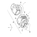
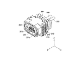
図1は、本発明の一実施の形態に係る差込側コネクタ1を含む一対の電気コネクタ100の一例を示す模式的斜視図である。尚、以下、図1中の矢印Xの方向をX方向、矢印Xの方向と逆向きの方向を−X方向として説明する。矢印Yの方向、Zの方向についても同様とする。
FIG. 1 is a schematic perspective view showing an example of a pair of
図1に示すように、電気コネクタ100は、差込側コネクタ1のメスハウジング200(ハウジング本体)が相手側コネクタ2のオスハウジング400に嵌合することにより電気的に接続されるコネクタである。差込側コネクタ1は、メスハウジング200に取り付けられた掛け止め金具300(バネ部材)を備えており、当該掛け止め金具300の作用により相手側コネクタ2に係止される。
As shown in FIG. 1, the
メスハウジング200の両側面には、メスハウジング200とオスハウジング400とが嵌合する方向(X方向)に垂直な方向(Z方向)に平行な案内溝210が設けられている。このメスハウジング200の案内溝210に沿って掛け止め金具300が−Z方向に向かって圧挿される。
On both side surfaces of the
図2に示すように、メスハウジング200の内部には、一対の第1接続端子201a,201bが設けられている。同じく、後述するオスハウジング400の内部には、一対の第2接続端子401a,401b(図11参照)が設けられている。当該オスハウジング400の内部に設けられた第2接続端子401a,401bには、電気的配線が接続されている。
As shown in FIG. 2, a pair of
オスハウジング400にメスハウジング200が嵌挿されて嵌合することにより、第1接続端子201aおよび第2接続端子401aと、第1接続端子201bおよび第2接続端子401bとがそれぞれ接合し、電気的導通が図られる。
By fitting and fitting the
次に、掛け止め金具300を備えたメスハウジング200およびオスハウジング400の形状について詳細に説明する。
Next, the shape of the
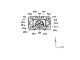
図2〜図7は、掛け止め金具300を備えた差込側コネクタ1の形状を説明するための模式図である。図2は、図1に示す差込側コネクタ1の正面図であり、図3は、図1に示す差込側コネクタ1の背面図であり、図4は、図1に示す差込側コネクタ1の左側面図であり、図5は、図1に示す差込側コネクタ1の平面図であり、図6は、図1に示す差込側コネクタ1の底面図である。また、図7は、図1に示す差込側コネクタ1の前方から視た斜視図である。尚、本実施形態に係る差込側コネクタ1の右側面図は図3に示す左側面図と対称である。
2-7 is a schematic diagram for demonstrating the shape of the insertion side connector 1 provided with the
図2〜図7に示すメスハウジング200は、後述するオスハウジング400(図11〜図14参照)の略四角柱筒形状を外包する略四角柱筒形状を有する。
The
図2に示すように、メスハウジング200の内部には、第1接続端子201a,201bが設けられている。本実施の形態に係る電気コネクタ100の極数は、2極である。そのため、第1接続端子201a,201bが2つ並んで設けられている。
As shown in FIG. 2,
図2及び図7に示すように、メスハウジング200の内部には、長方形リブ202とT字リブ203とが形成されている。これらの長方形リブ202とT字リブ203とには、それぞれテーパ形状が形成されている。このテーパ形状は、第1接続端子201a,201bおよび後述するオスハウジング400の第2接続端子401a,401bとの嵌挿をスムーズにさせるとともに、嵌合時に長方形リブ202とT字リブ203と、後述するオスハウジング400の長方形溝402およびT字溝403との密着度を向上させるために設けられる。
As shown in FIGS. 2 and 7,
さらに、これらの長方形リブ202とT字リブ203との形状は、オスハウジング400とメスハウジング200との逆嵌合を防止するために設けられている。すなわち、長方形リブ202とオスハウジング400のT字溝403(図11参照)とは嵌合せず、T字リブ203と長方形溝402(図11参照)とは嵌合しないからである。また、これらの長方形リブ202とT字リブ203との形状は、コネクタを嵌合させた後、相手側コネクタ2に対して差込側コネクタ1がX方向を軸として回転することを防止する効果も有する。
Further, the shapes of the
また、図2に示すように、メスハウジング200の4隅には、スリットリブ205a,205b,205c,205dが設けられる。これらのスリットリブ205a,205b,205c,205dは、メスハウジング200と後述するオスハウジング400との嵌合完了時にオスハウジング400のスリット405a,405b,405c,405dと当接するように設けられている。
As shown in FIG. 2, slit
さらに、メスハウジング200の各面のうち一の面には、スリット250a,250bが設けられ、他の一の面には、スリット250c,250dが設けられ、他の一の面には、スリット250e,250fが設けられ、他の一の面には、スリット250g,250h,250iが設けられる。
Further,
これらのスリット250a〜250iは、メスハウジング200とオスハウジング400との嵌合完了時にオスハウジング400のリブ450a〜450iと当接するように設けられている。
These
また、これらのメスハウジング200におけるリブ205a,205b,205c,205dおよびオスハウジング400の対応するスリット250a〜250iには、中心から外側に向けて幅が狭くなるテーパ形状が設けられる。
Further, the
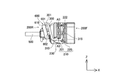
また、図4に示すように、メスハウジング200の側面には、Z方向と平行な方向に案内溝210が形成されている。この案内溝210は、立ち壁220,221およびハウジング内に貫通する開口部222を含む。また、開口部222は案内溝210のほぼ中央部に設けられる。
As shown in FIG. 4, a
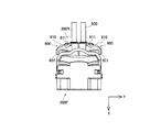
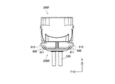
続いて、図4、図5及び図6に示すように、X方向におけるメスハウジング200の端部である押圧操作側端部200Rからは、第1接続端子201a,201b(図2(a)参照)に接続されたケーブル500が引き出されている。押圧操作側端部200Rは、X方向においてオスハウジング400に対向する嵌合側端部200Fと逆側に位置する。そして、押圧操作側端部200Rにおいて、嵌合方向(X方向)に押圧操作される押圧部600が形成されている。
Subsequently, as shown in FIGS. 4, 5, and 6,
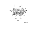
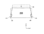
押圧部600は、嵌合方向から見て後述する掛け止め金具300(バネ部材)の一部を覆うように形成されている(図3参照)。そして押圧部600における掛け止め金具300に対向する対向部601はY方向と平行な平面となるように形成されている(図4及び図5参照)。押圧部600は、ケーブル500を挟んで一対で設けられる押圧部分610・610からなり、一対の押圧部分610・610はケーブル500を挟んで対称に形成されている。また、押圧部分610は、嵌合側端部200Fに近づくにつれて押圧部分610が広がるように形成される斜面611を備えている(図3、図5、図6参照)。
The
また、図3及び図4に示すように、押圧部分610には、当該斜面611側から嵌合方向に向かって形成され、対向部601側に位置する側面部に貫通する貫通孔602を有している。この貫通孔602により押圧操作時における滑り止め機能が発揮されるとともに、メスハウジング200の軽量化及び成形に要する材料の削減が可能である。
As shown in FIGS. 3 and 4, the
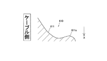
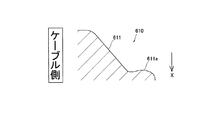
図8は、図3における一点鎖線A1で示すメスハウジング200の断面を模式的に示す断面図であり、図9は、一点鎖線A2で示すメスハウジング200の断面を模式的に示す断面図である。図8及び図9に示すように、斜面611は、ケーブル500から離れた方向の端部において反った形状を有しており、当該端部において突起部611aが形成されている。突起部611aは、−X方向に向かって突出するように形成されている。
8 is a cross-sectional view schematically showing a cross section of the
また、押圧部分610におけるケーブル500と反対側の縁部は、図3において二本の一点鎖線L1・L1で示すように、Z方向に向かうほど、それぞれ相互に近接するように傾斜している。
Further, the edge of the
また、図1に示すようにメスハウジング200は、−Z方向に向かってメスハウジング200が広がるように形成される斜面230を両側面に備えている。掛け止め金具300は、斜面230を両側方から挟み込むように設置されている
In addition, as shown in FIG. 1, the
掛け止め金具300は、バネ性を有する金属により構成されている。例えば、掛け止め金具300は、ばね鋼またはステンレス鋼などの金属材料により形成される。また、掛け止め金具300の使用状況に応じて、コーティング処理等が施されていてもよい。例えば、掛け止め金具300の耐候性または耐食性を向上させる場合には、亜鉛めっき、塗装またはクロメート処理等が施される。
The
図7に示すように、掛け止め金具300は、断面が略円形の一本の部材を屈曲させることにより形成される。掛け止め金具300には、上記の開口部222に対してメスハウジング200の中心方向に弾性を有するように湾曲して形成された掛け止め部315(図2参照)が設けられる。
As shown in FIG. 7, the
図4及び図10を用いて掛け止め金具300の動きについて説明する。
図10は、図4におけるA3−A3断面における掛け止め金具300の動きを模式的に示す図である。
The movement of the
FIG. 10 is a diagram schematically showing the movement of the
図4に示すように、掛け止め金具300は、メスハウジング200の案内溝210に沿ってZ方向と平行にスライド可能に設けられている。掛け止め金具300の押圧操作部301が−Z方向に向かって押圧され、掛け止め金具300が−Z方向にスライドした場合、案内溝210の開口部222からメスハウジング200の中央部に突出して設けられた掛け止め部315が案内溝210に沿って移動する。
As shown in FIG. 4, the
このとき、図10に示すように、掛け止め金具300におけるメスハウジング200の側方に位置する当接部310(図4参照)が、メスハウジング200の側面に形成された、−Z方向に向かって上り坂となる斜面230に乗り上げるように移動する。これより、掛け止め金具300はY方向において開くように変形するとともに、メスハウジング200の両側面に位置する掛け止め部315も、−Z方向に変位するとともに、Y方向と平行に互いに離れるように変位して、開口部222から突出しなくなる。即ち、係止状態から非係止状態に移行することになる。
At this time, as shown in FIG. 10, the contact portion 310 (see FIG. 4) located on the side of the
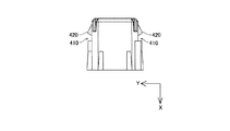
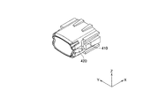
次に、相手側コネクタ2の形状について説明する。図11〜図14は、相手側コネクタ2の形状を説明するための模式図である。図11は相手側コネクタ2の正面図を示し、図12は相手側コネクタ2の左側面図を示し、図13は相手側コネクタ2の底面図を示す。また、図14は相手側コネクタ2の斜視図を示す。 Next, the shape of the mating connector 2 will be described. FIGS. 11 to 14 are schematic views for explaining the shape of the mating connector 2. 11 shows a front view of the mating connector 2, FIG. 12 shows a left side view of the mating connector 2, and FIG. 13 shows a bottom view of the mating connector 2. FIG. 14 is a perspective view of the mating connector 2.
オスハウジング400は、上述したメスハウジング200の略四角柱筒形状により内包される略四角柱筒形状を有する。
The
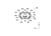
図11に示すように、オスハウジング400の内部には、第2接続端子401a,401bが設けられている。図2の第1の接続端子と同様に、本実施の形態に係る電気コネクタ100の極数は、2極である。そのため、第2接続端子401a,401bが、2つ並んで設けられている。オスハウジング400とメスハウジング200との嵌合時には、第2接続端子401aが、図2の第1接続端子201aと接続され、第2接続端子401bが、図2の第1接続端子201bと接続される。
As shown in FIG. 11,
図11に示すように、オスハウジング400の内部には、長方形溝402とT字溝403とが形成されている。これらの長方形溝402とT字溝403とには、テーパ形状が形成されている。このテーパ形状は、第2接続端子401a,401bおよびメスハウジング200の第1接続端子201a,201bとの嵌挿をスムーズにするとともに、嵌合時に長方形リブ202とT字リブ203との密着度を向上させるために設けられる。
As shown in FIG. 11, a
さらに、オスハウジング400とメスハウジング200との逆嵌合を防止するため、長方形溝402とT字溝403との形状が異なるように設けられている。また、長方形溝402とT字溝403とを設けることによりメスハウジング200とオスハウジング400との勘合時における捩り方向の耐性を向上させることができる。
Furthermore, in order to prevent reverse fitting of the
また、図11に示すように、オスハウジング400の4隅には、スリット405a,405b,405c,405dが設けられている。このスリット405a,405b,405c,405dは、オスハウジング400とメスハウジング200との嵌挿完了時にメスハウジング200の内部のスリットリブ205a,205b,205c,205dと当接するように設けられる。
As shown in FIG. 11,
さらに、オスハウジング400の各面のうち一の面には、リブ450a,450bが設けられ、他の一の面には、リブ450c,450d,450eが設けられ、他の一の面には、リブ450f,450gが設けられ、他の一の面には、リブ450h,450iが設けられる。これらのリブ450a〜450iは、オスハウジング400とメスハウジング200との嵌合完了時にメスハウジング200のスリット250a〜250iと当接するように設けられている。
Furthermore,
また、これらのスリット405a,405b,405c,405dおよびリブ450a〜450iには、中心から外側に向けて幅が狭くなるテーパ形状が設けられる。
The
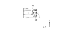
続いて、図12及び図14に示すように、オスハウジング400には、Z方向と平行な方向に固定溝410が形成されている。固定溝410は、YZ平面と平行な断面において略V字形状が形成された溝から形成されており、略V字形状の一方の傾斜が緩やかで、他方の傾斜が急に形成されている。すなわち、掛け止め金具300がZ方向に移動しやすく、−Z方向に移動し難い状態で略V字形状が形成されている。
Subsequently, as shown in FIGS. 12 and 14, a fixing
また、図13及び図14に示すように、オスハウジング400の端部から固定溝410に向かって矢印X1の方向に凸形状部420が設けられている。凸形状部420は、XY平面における断面において略台形状からなる。
As shown in FIGS. 13 and 14, a
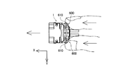
次に、メスハウジング200をオスハウジング400に嵌合させる動作について説明する。図15は、作業者が指先でメスハウジング200を嵌合方向へ押圧操作している状態を模式的に示した図である。
図15に示すように、作業者は、例えば、メスハウジング200における一対の押圧部分610・610の一方に親指を、他方に人差し指を接触させて、挟み込むように押圧部600を保持し、そのまま、オスハウジング400に向かって嵌合方向(X方向)に押圧操作することによりメスハウジング200をオスハウジング400に嵌合させる。
Next, an operation for fitting the
As shown in FIG. 15, for example, the operator holds the
ここで、嵌合時に、図12に示す凸形状部420の面上をメスハウジング200の開口部222から突出した掛け止め部315が矢印X1の方向に移動するとともに、凸形状部420に沿って嵌合方向と垂直方向に変位する。そして、掛け止め部315は、凸形状部420を乗り越えて、固定溝410に滑落する。この場合、掛け止め部315は、掛け止め金具300の弾性回復により、固定溝410に落ち込み、オスハウジング400に対して、掛け止め部315が係止され、嵌合離脱方向(−X方向)へのメスハウジング200の変位が拘束されることになる。
Here, at the time of fitting, the latching
このように、掛け止め金具300の弾性変形を伴いながら嵌合されるため、作業者は、掛け止め金具300を弾性変形させるために必要な押圧力をメスハウジング200に与える必要がある。
As described above, since the
本実施形態のメスハウジング200の形状によれば、押圧部600には斜面611が形成されているため(図3、図5参照)、指先の接触面積を大きくすることができるとともに、指先がフィットしやすく、上記押圧力を容易に作用させることが可能となる。また、斜面611の端部に突起部611a(図3、図8、図9参照)が形成されているため、指先が引っかかりやすく、滑りにくい。これより、確実に力を伝えることが可能となる。
According to the shape of the
また、嵌合方向に対して垂直な方向(Y方向と平行な方向)に掛け止め部315が変位するように掛け止め金具300を変形させて係止を解除する構造であるため、係止状態と非係止状態との移行時における掛け止め金具300の変形量をより小さくでき、変形に要する力も小さくてすむ。その結果、嵌合の際に小さい力で嵌合することができる。
Further, since the
そして、押圧部600の掛け止め金具300に対向する対向部601がY方向と平行な平面として形成されているので、掛け止め金具300のY方向における変形を妨げることはなく、掛け止め金具300の変形に要する力を小さくすることができる。
And since the opposing
さらに、掛け止め金具300は、押圧方向から押圧部600に覆われているため、押圧時に指先が掛け止め金具300に触れにくく、指で掛け止め金具300の変形を拘束しにくい。よって、より小さな押圧力で嵌合を行うことができる。
Furthermore, since the latching
また、一対の押圧部分610・610はケーブル500を挟んで対称に形成されているため、メスハウジング200に対して、ケーブル500を挟んで対称な押圧力を付与しやすくなるため、より小さい力で嵌合可能となる。
In addition, since the pair of
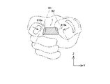
また、一対の押圧部分610・610の縁部610aはそれぞれ相互に近接するように傾斜している。図16に、相手側コネクタ2から視た押圧部分610と作業者の指先との位置関係を説明する模式図を示す。図16に示すように、押圧部分610の縁部610aが近接する側から親指と人差し指で押圧部を挟み込むように差込側コネクタ1を保持して押圧した場合、縁部610aが傾斜していることにより、各指先で挟み込む面(点線B1、B2で示す)の角度と縁部610aの傾斜角度とが近づくため、各指先が押圧部にフィットしやすくなる。したがって、押圧しやすく、安定して押圧操作を行うことが可能となる。
Further, the
特に、嵌合の際にバネ部材の変形を伴うようなコネクタにおいては、必要な押圧力が他のコネクタに比べて大きくなるため、本実施形態のようにコネクタハウジングを押圧しやすい形状にすることは効果的である。 In particular, in a connector that involves deformation of a spring member at the time of fitting, the required pressing force is greater than that of other connectors, so the connector housing should be shaped to be easily pressed as in this embodiment. Is effective.
以上、本発明の実施形態について説明したが、本発明は上述の実施の形態に限られるものではなく、特許請求の範囲に記載した限りにおいて様々に変更して実施することができるものである。 Although the embodiments of the present invention have been described above, the present invention is not limited to the above-described embodiments, and various modifications can be made as long as they are described in the claims.
1 差込側コネクタ
2 相手側コネクタ
200 メスハウジング(ハウジング本体)
200F 嵌合側端部
200R 押圧操作側端部
300 掛け止め金具(バネ部材)
400 オスハウジング
500 ケーブル
600 押圧部
601 対向部
610 押圧部分
610a 縁部
611 斜面
611a 突起部
1 Plug-in side connector 2
200F
400
Claims (3)
前記ハウジング本体が相手側コネクタに向かった嵌合方向に押圧されることにより、前記バネ部材の弾性変形を伴いながら当該相手側コネクタに嵌合されるとともに当該バネ部材の弾性回復により当該相手側コネクタに対して当該バネ部材が係止されて嵌合離脱方向の変位が固定される差込側コネクタであって、
前記ハウジング本体は、前記相手側コネクタに対向する嵌合側端部と逆側の端部である押圧操作側端部において、前記嵌合方向に押圧操作される押圧部を有し、
前記押圧部は、前記嵌合側端部に近づくにつれて当該押圧部が広がるように形成される一対の斜面と、当該斜面から突出する突起部とを有し、
前記押圧部における前記斜面の拡開側の両縁部が、前記嵌合方向から見て互いに近づくように傾斜していることを特徴とする差込側コネクタ。 A housing body, and a spring member attached to the housing body,
When the housing body is pressed in the fitting direction toward the mating connector, the mating connector is fitted into the mating connector while elastically deforming the spring member, and the mating connector is elastically restored. A plug-side connector in which the spring member is locked and the displacement in the fitting / removing direction is fixed,
The housing body has a pressing portion that is pressed in the fitting direction at a pressing operation side end that is an end opposite to the fitting side end facing the mating connector,
The pressing part has a pair of slopes formed so that the pressing part spreads as approaching the fitting side end, and a protruding part protruding from the slope ,
An insertion-side connector characterized in that both edge portions on the expanding side of the inclined surface of the pressing portion are inclined so as to approach each other when viewed from the fitting direction .
前記押圧部は、前記嵌合方向から見て前記バネ部材の少なくとも一部を覆うように形成されているとともに当該バネ部材に対向する対向部は前記弾性変形の方向と平行な平面となるように形成されていることを特徴とする請求項1に記載の差込側コネクタ。 The spring member is installed so as to sandwich the housing main body from both sides, and is elastically deformed so as to spread in a direction perpendicular to the fitting direction at the time of transition to the fitted state and reaches the fitted state. And locked against the mating connector by elastic recovery,
The pressing portion is formed so as to cover at least a part of the spring member when viewed from the fitting direction, and the facing portion facing the spring member is a plane parallel to the elastic deformation direction. The insertion side connector according to claim 1, wherein the insertion side connector is formed.
Priority Applications (1)
| Application Number | Priority Date | Filing Date | Title |
|---|---|---|---|
| JP2006250422A JP4828362B2 (en) | 2006-09-15 | 2006-09-15 | Plug-in connector |
Applications Claiming Priority (1)
| Application Number | Priority Date | Filing Date | Title |
|---|---|---|---|
| JP2006250422A JP4828362B2 (en) | 2006-09-15 | 2006-09-15 | Plug-in connector |
Publications (2)
| Publication Number | Publication Date |
|---|---|
| JP2008071665A JP2008071665A (en) | 2008-03-27 |
| JP4828362B2 true JP4828362B2 (en) | 2011-11-30 |
Family
ID=39293068
Family Applications (1)
| Application Number | Title | Priority Date | Filing Date |
|---|---|---|---|
| JP2006250422A Active JP4828362B2 (en) | 2006-09-15 | 2006-09-15 | Plug-in connector |
Country Status (1)
| Country | Link |
|---|---|
| JP (1) | JP4828362B2 (en) |
Families Citing this family (2)
| Publication number | Priority date | Publication date | Assignee | Title |
|---|---|---|---|---|
| KR101091320B1 (en) | 2009-09-16 | 2011-12-07 | 현대자동차주식회사 | Automotive High Voltage Connectors |
| JP6534301B2 (en) * | 2015-06-17 | 2019-06-26 | 矢崎総業株式会社 | Connector device |
Family Cites Families (4)
| Publication number | Priority date | Publication date | Assignee | Title |
|---|---|---|---|---|
| JPS62152379A (en) * | 1985-12-25 | 1987-07-07 | Matsushita Electric Ind Co Ltd | 2-direction minute displacement device |
| JPS63184581A (en) * | 1987-11-21 | 1988-07-30 | ヤマハ発動機株式会社 | Car for travelling on wasteland |
| JP3775345B2 (en) * | 2002-05-28 | 2006-05-17 | 住友電装株式会社 | connector |
| JP4361023B2 (en) * | 2005-01-19 | 2009-11-11 | 日本圧着端子製造株式会社 | Electrical connector |
-
2006
- 2006-09-15 JP JP2006250422A patent/JP4828362B2/en active Active
Also Published As
| Publication number | Publication date |
|---|---|
| JP2008071665A (en) | 2008-03-27 |
Similar Documents
| Publication | Publication Date | Title |
|---|---|---|
| JP2000003763A (en) | Connector locking mechanism | |
| US6676433B1 (en) | Connector | |
| KR101977535B1 (en) | Connector and connector assembly | |
| JP2006085989A (en) | Insertion guide for ffc | |
| US10199768B2 (en) | Connector | |
| KR20130138673A (en) | Connector | |
| US7699642B2 (en) | Connector having a locking mechanism excellent in operability | |
| JP3741351B2 (en) | Half-mating prevention connector | |
| JP5005498B2 (en) | Latch bracket, connector housing with latch bracket and connector with latch bracket | |
| JP4755056B2 (en) | connector | |
| JPH10199622A (en) | Double lock for connector | |
| JP2004146182A (en) | Connector | |
| JP4989534B2 (en) | connector | |
| US8425248B2 (en) | Plug electrical connector with elastic latch | |
| US12199370B2 (en) | Connector and electronic device | |
| JP4828362B2 (en) | Plug-in connector | |
| JP4440122B2 (en) | Flexible wiring member connector | |
| JP2019023961A (en) | Terminal having contact piece, connector, and connector device | |
| JP6244832B2 (en) | Electrical connector | |
| JP2016115404A (en) | connector | |
| US12080966B2 (en) | Connector and electronic device | |
| JP2008097956A (en) | Connector locking mechanism | |
| JP2004311113A (en) | Electrical connector | |
| JP4828363B2 (en) | Plug-in connector | |
| JP2008108711A (en) | Card edge connector |
Legal Events
| Date | Code | Title | Description |
|---|---|---|---|
| A621 | Written request for application examination |
Free format text: JAPANESE INTERMEDIATE CODE: A621 Effective date: 20090826 |
|
| A977 | Report on retrieval |
Free format text: JAPANESE INTERMEDIATE CODE: A971007 Effective date: 20110525 |
|
| A131 | Notification of reasons for refusal |
Free format text: JAPANESE INTERMEDIATE CODE: A131 Effective date: 20110531 |
|
| A521 | Request for written amendment filed |
Free format text: JAPANESE INTERMEDIATE CODE: A523 Effective date: 20110720 |
|
| TRDD | Decision of grant or rejection written | ||
| A01 | Written decision to grant a patent or to grant a registration (utility model) |
Free format text: JAPANESE INTERMEDIATE CODE: A01 Effective date: 20110913 |
|
| A01 | Written decision to grant a patent or to grant a registration (utility model) |
Free format text: JAPANESE INTERMEDIATE CODE: A01 |
|
| A61 | First payment of annual fees (during grant procedure) |
Free format text: JAPANESE INTERMEDIATE CODE: A61 Effective date: 20110914 |
|
| FPAY | Renewal fee payment (event date is renewal date of database) |
Free format text: PAYMENT UNTIL: 20140922 Year of fee payment: 3 |
|
| R150 | Certificate of patent or registration of utility model |
Ref document number: 4828362 Country of ref document: JP Free format text: JAPANESE INTERMEDIATE CODE: R150 Free format text: JAPANESE INTERMEDIATE CODE: R150 |
|
| R250 | Receipt of annual fees |
Free format text: JAPANESE INTERMEDIATE CODE: R250 |
|
| R250 | Receipt of annual fees |
Free format text: JAPANESE INTERMEDIATE CODE: R250 |
|
| R250 | Receipt of annual fees |
Free format text: JAPANESE INTERMEDIATE CODE: R250 |
|
| R250 | Receipt of annual fees |
Free format text: JAPANESE INTERMEDIATE CODE: R250 |
|
| R250 | Receipt of annual fees |
Free format text: JAPANESE INTERMEDIATE CODE: R250 |
|
| R250 | Receipt of annual fees |
Free format text: JAPANESE INTERMEDIATE CODE: R250 |
|
| R250 | Receipt of annual fees |
Free format text: JAPANESE INTERMEDIATE CODE: R250 |
|
| R250 | Receipt of annual fees |
Free format text: JAPANESE INTERMEDIATE CODE: R250 |
|
| R250 | Receipt of annual fees |
Free format text: JAPANESE INTERMEDIATE CODE: R250 |
|
| R250 | Receipt of annual fees |
Free format text: JAPANESE INTERMEDIATE CODE: R250 |
|
| R250 | Receipt of annual fees |
Free format text: JAPANESE INTERMEDIATE CODE: R250 |
|
| R250 | Receipt of annual fees |
Free format text: JAPANESE INTERMEDIATE CODE: R250 |
