JP4827792B2 - Discharge tray support structure and image forming apparatus - Google Patents
Discharge tray support structure and image forming apparatus Download PDFInfo
- Publication number
- JP4827792B2 JP4827792B2 JP2007120266A JP2007120266A JP4827792B2 JP 4827792 B2 JP4827792 B2 JP 4827792B2 JP 2007120266 A JP2007120266 A JP 2007120266A JP 2007120266 A JP2007120266 A JP 2007120266A JP 4827792 B2 JP4827792 B2 JP 4827792B2
- Authority
- JP
- Japan
- Prior art keywords
- discharge tray
- tray
- paper discharge
- image forming
- forming apparatus
- Prior art date
- Legal status (The legal status is an assumption and is not a legal conclusion. Google has not performed a legal analysis and makes no representation as to the accuracy of the status listed.)
- Expired - Fee Related
Links
Images


Landscapes
- Pile Receivers (AREA)
Description
本発明は、ファクシミリ、MFP(マルチファンクションプリンター)、複写機、プリンター等の画像形成装置における排紙トレイの支持構造、及び、その画像形成装置に関する。 The present invention relates to a support structure for a paper discharge tray in an image forming apparatus such as a facsimile, an MFP (multifunction printer), a copying machine, and a printer, and the image forming apparatus.
従来、画像形成装置の排紙トレイの支持構造として、例えば、排紙トレイの後部を回動支点にさせて、排紙トレイを装置の内方向へ回動可能にさせると共に、その回動角度を段階的に保持可能にして、排紙トレイの設置角度を可変可能に支持させたものがある。
この構造によれば、用紙のサイズに応じ、排紙トレイの長さ、設置角度、位置を変化させることで、簡単な機構で省スペース化、低コスト化を図ることができる、としている(特許文献1)。
この特許文献1に例示された画像形成装置は、装置本体内から記録紙が排紙される、所謂、胴内排紙タイプの画像形成装置であるが、画像形成装置によっては、その天面から記録紙が搬出されるものがある。その場合の排紙トレイは、画像形成装置を構成する筐体をそのまま利用して一体化されている場合が多い。
ところで、この種の画像形成装置は、小型のものと大型のものとがあるが、とりわけ小型の画像形成装置は、大型の画像形成装置と異なり、その設置場所に自由度があることから、ラックやサイドボード等の高所に設置されているケースが往々にしてある。
According to this structure, by changing the length, installation angle, and position of the discharge tray according to the paper size, it is possible to save space and reduce costs with a simple mechanism (patent) Reference 1).
The image forming apparatus exemplified in
By the way, this type of image forming apparatus includes a small type and a large type, but a small image forming apparatus has a degree of freedom in its installation place unlike a large image forming apparatus. There are many cases that are installed in high places such as a sideboard.
しかしながら、上記した従来の排紙トレイは、その後部を回動支点にさせて、排紙トレイを上方へ回動可能にさせたものや、画像形成装置を構成する筐体をそのまま利用して一体化されたものであるため、そのような排紙トレイを備えた画像形成装置を、ラックやサイドボード等の高所に設置させると、排紙トレイ上の記録紙が取り出しにくく、利便性に欠けていた。
そこで本発明は、このような状況に鑑みてなされたものであり、上記問題点を解決できる排紙トレイの支持構造及び画像形成装置を提供することを目的とする。
However, the above-described conventional paper discharge tray is integrated using the rear portion of the paper discharge tray as a rotation fulcrum so that the paper discharge tray can be rotated upward, or the housing constituting the image forming apparatus. Therefore, if an image forming apparatus equipped with such a paper discharge tray is installed in a high place such as a rack or a sideboard, the recording paper on the paper discharge tray is difficult to take out, which is not convenient. It was.
SUMMARY An advantage of some aspects of the invention is that it provides a discharge tray support structure and an image forming apparatus that can solve the above problems.
上記技術課題を解決するために、本発明の請求項1にかかる排紙トレイの支持構造は、記録紙に画像を形成する画像形成部を備えた画像形成装置本体の上面に支持され、該画像形成装置本体に設けられた排紙部から排紙された記録紙を載置させる排紙トレイの支持構造であって、前記排紙トレイは、前記画像形成部により画像形成されて排出された前記記録紙を載置させるトレイ面と、該トレイ面に記録紙が載置される第1の位置と前記トレイ面を下方に傾斜させて前記トレイ面上の記録紙を取り出すための第2の位置との間で前記トレイ面を移動させる移動機構と、を備え、前記排紙トレイが前記第2の位置のとき、少なくとも前記トレイ面の前記記録紙排出方向下流側端部が、前記画像形成装置本体の側面よりも突出し、且つ該画像形成装置本体の上面よりも下方に位置し、前記排紙トレイには、前記トレイ面から突出されるように、前記排紙トレイの傾動方向側へ回動可能なコロが枢着され、該コロは、前記支承面と前記排紙トレイとの係合に連係されて、前記排紙トレイが前記第2の位置にあるときに前記トレイ面から突出されると共に前記排紙トレイが前記第1の位置にあるときに該排紙トレイに没入される出没機構を介して前記排紙トレイに設けられていることを特徴とする。
請求項2にかかる排紙トレイの支持構造は、請求項1において、前記画像形成装置本体は、前記排紙トレイを支承させる支承面を備え、前記排紙トレイは、前記支承面から上方に向かって回動可能に、かつ、所要の回動角度でもって前記画像形成装置本体に衝合可能に枢支されていることを特徴とする。
請求項3にかかる排紙トレイの支持構造は、請求項2において、前記排紙トレイを衝合方向に付勢させる付勢手段を備えていることを特徴とする。
In order to solve the above technical problem, a support structure for a paper discharge tray according to a first aspect of the present invention is supported on an upper surface of an image forming apparatus main body including an image forming unit for forming an image on a recording sheet. A support structure for a paper discharge tray on which recording paper discharged from a paper discharge unit provided in a main body of the forming apparatus is placed, and the paper discharge tray is formed and discharged by the image forming unit. A tray surface on which the recording paper is placed, a first position where the recording paper is placed on the tray surface, and a second position for taking out the recording paper on the tray surface by inclining the tray surface downward A moving mechanism for moving the tray surface between the image forming apparatus and at least a downstream end of the tray surface in the recording paper discharge direction when the discharge tray is at the second position. Projecting from the side of the main body and forming the image Located below the upper surface of the Okimoto body, the paper discharge tray, as protruded from the tray surface, wherein the rotatable rollers are pivotally to the tilting direction of the discharge tray, the rollers are And the support surface and the discharge tray are engaged with each other so that the discharge tray protrudes from the tray surface when the discharge tray is in the second position, and the discharge tray is in the first position. It is characterized in that it is provided in the paper discharge tray through a retracting mechanism that is inserted into the paper discharge tray when it is in the position.
According to a second aspect of the present invention, there is provided the discharge tray support structure according to the first aspect, wherein the main body of the image forming apparatus includes a support surface for supporting the discharge tray, and the discharge tray faces upward from the support surface. And is pivotally supported by the image forming apparatus main body at a required rotation angle so as to be able to collide with the image forming apparatus main body.
According to a third aspect of the present invention, there is provided a discharge tray support structure according to the second aspect, further comprising biasing means for biasing the discharge tray in the abutting direction.
請求項4にかかる排紙トレイの支持構造は、請求項1において、前記画像形成装置本体は、前記排紙トレイを支承させる支承面を底面として前記排紙トレイを収納させる収納凹部を備え、前記排紙トレイと前記画像形成装置本体とが、前記排紙トレイを前記画像形成装置本体から突出可能に前記収納凹部に係合させると共に前記画像形成装置本体から突出された前記排紙トレイを下方に向かって回動可能に係合させる係合手段を介して接続されると共に、前記排紙トレイが、弾性部材を挟んで所要の回動角度でもって前記画像形成装置本体と衝合可能に構成されていることを特徴とする。
請求項5にかかる排紙トレイの支持構造は、請求項4において、前記係合手段は、前記収納凹部の内面に前記排紙トレイのスライド方向に延設された長孔または長溝からなる係合部と、前記排紙トレイの外面から突設され、前記長孔または前記長溝に遊嵌された枢軸からなる被係合部とを備えてなることを特徴とする。
請求項6にかかる排紙トレイの支持構造は、請求項4または5において、前記収納凹部の内側に設けられ、前記画像形成装置本体から突出された前記排紙トレイを前記画像形成装置本体の内方側へ引っ張る引っ張り手段を備えていることを特徴とする。
According to a fourth aspect of the present invention, there is provided a discharge tray support structure according to the first aspect, wherein the image forming apparatus main body includes a storage recess for storing the discharge tray with a support surface for supporting the discharge tray as a bottom surface. A paper discharge tray and the image forming apparatus main body engage the paper discharge tray with the housing recess so that the paper discharge tray can protrude from the image forming apparatus main body, and the paper discharge tray protruded from the image forming apparatus main body faces downward. The paper discharge tray is configured to be able to collide with the image forming apparatus main body at a required rotation angle with an elastic member interposed therebetween. It is characterized by.
According to a fifth aspect of the present invention, there is provided the discharge tray support structure according to the fourth aspect, wherein the engagement means is an engagement formed by a long hole or a long groove extending in the sliding direction of the discharge tray on the inner surface of the storage recess. And an engaged portion formed of a pivot projecting from the outer surface of the paper discharge tray and loosely fitted in the long hole or the long groove.
According to a sixth aspect of the present invention, there is provided the discharge tray supporting structure according to the fourth or fifth aspect, wherein the discharge tray is provided inside the housing recess and protrudes from the image forming apparatus main body. It is characterized by having a pulling means for pulling to the side.
請求項7にかかる排紙トレイの支持構造は、請求項1乃至6の何れか一項において、前記排紙トレイは、前記排紙部の排紙方向側に傾動されるように、前記画像形成装置本体に支持されていることを特徴とする。
請求項8にかかる排紙トレイの支持構造は、請求項1乃至6の何れか一項において、前記排紙トレイは、前記排紙部の排紙方向と平面視直交方向側に傾動されるように、前記画像形成装置本体に支持されていることを特徴とする。
According to a seventh aspect of the present invention, there is provided a discharge tray support structure according to any one of the first to sixth aspects, wherein the discharge tray is tilted toward a discharge direction side of the discharge section. It is supported by the apparatus main body.
According to an eighth aspect of the present invention, there is provided the discharge tray supporting structure according to any one of the first to sixth aspects, wherein the discharge tray is tilted in a direction perpendicular to the sheet discharge direction of the sheet discharge portion. Further, the image forming apparatus is supported by the main body of the image forming apparatus .
請求項9にかかる排紙トレイの支持構造は、請求項1において、前記排紙トレイは、そのトレイ面と前記支承面との間に空隙が形成されるように形設されてなり、前記出没機構は、前記トレイ面に形成された凹部と、該凹部内に遊嵌され前記コロを枢支させた軸受けと、該軸受けと前記凹部との間に張架され、前記軸受けを上方へ付勢させる弾性部材と、前記凹部に隣接され前記支承面から突設されたボスと、前記トレイ面と反対の裏面から垂設された軸支部に中途部が枢支され、一端が前記軸受けに係合可能に配置されると共に他端が前記ボスと係合可能に配置されて、シーソー状に揺動可能なリンクとを備え、前記排紙トレイが前記第1の位置にあるときに、前記ボスによって前記リンクの一端が押し上げられて前記コロが前記排紙トレイに没入可能に、かつ、前記排紙トレイが前記第2の位置にあるときに、前記ボスと前記リンクの一端との係合が解除されて前記コロが前記トレイ面から突出可能に構成されてなることを特徴とする。
請求項10にかかる排紙トレイの支持構造は、請求項1乃至9の何れか一項において、前記排紙トレイが前記第2の位置にあるときにおいて下側となるトレイ端部から出没可能に設けられ、前記トレイ面を延長させる延長トレイを備えていることを特徴とする。
According to a ninth aspect of the present invention, there is provided a discharge tray support structure according to the first aspect , wherein the discharge tray is formed so that a gap is formed between the tray surface and the support surface, The mechanism includes a recess formed in the tray surface, a bearing loosely fitted in the recess and pivotally supporting the roller, and is stretched between the bearing and the recess to bias the bearing upward. An elastic member, a boss adjacent to the recess and projecting from the support surface, and a shaft support portion suspended from the back surface opposite to the tray surface. The other end is disposed so as to be engageable with the boss, and is provided with a seesaw-like rocking link, and when the paper discharge tray is in the first position, the boss One end of the link is pushed up so that the roller is in the discharge tray. Immersive capable to, and the when the discharge tray is in said second position, the boss and the one end and the roller engagement is released of the link is configured to be projected from the tray surface It is characterized by becoming.
According to a tenth aspect of the present invention, there is provided the support structure for the discharge tray according to any one of the first to ninth aspects, wherein the discharge tray can be projected and retracted from the lower end of the tray when the discharge tray is at the second position. An extension tray is provided and extends the tray surface.
請求項11にかかる排紙トレイの支持構造は、請求項10において、前記延長トレイに取手が設けられていることを特徴とする。 According to an eleventh aspect of the present invention, there is provided a paper discharge tray support structure according to the tenth aspect , wherein a handle is provided on the extension tray.
請求項12にかかる発明は、請求項1乃至11の何れか一項に記載の排紙トレイの支持構造を備えた画像形成装置であって、前記排紙トレイが移動したことを検知するセンサと、前記排紙トレイが移動したことを前記センサが検知した場合に印刷ジョブを停止する制御手段と、を備えたことを特徴とする。
請求項13にかかる発明は、請求項1乃至11の何れか一項に記載の排紙トレイの支持構造を備えた画像形成装置であって、前記排紙トレイが移動したことを検知するセンサと、前記排紙トレイが移動したことを前記センサが検知したときに印字動作中であった場合には、搬送中の記録紙を排出し印字動作を停止する制御手段と、を備えたことを特徴とする。
According to a twelfth aspect of the present invention, there is provided an image forming apparatus including the discharge tray support structure according to any one of the first to eleventh aspects, wherein the sensor detects that the discharge tray has moved. And a control means for stopping the print job when the sensor detects that the paper discharge tray has moved.
According to a thirteenth aspect of the present invention, there is provided an image forming apparatus comprising the discharge tray support structure according to any one of the first to eleventh aspects, wherein the sensor detects that the discharge tray has moved. And a control means for discharging the recording paper being conveyed and stopping the printing operation when the printing operation is in progress when the sensor detects that the paper discharge tray has moved. And
本発明によれば、記録紙を載置するトレイ面の記録紙排出方向下流側端部が、画像形成装置本体の側面よりも突出し、且つ該画像形成装置本体の上面よりも下方に位置するように排紙トレイを傾動可能にして、排紙トレイの第1の位置と第2の位置の選択を可能にしたから、排紙トレイを第1の位置にすることで、排紙部から排紙した記録紙をトレイ面に確実に載置でき、また、排紙トレイを第2の位置にすることで、画像形成装置本体の水平方向や画像形成装置本体より下方から、記録紙を取り出すことができる。また、排紙トレイが第2の位置にあるときには、排紙トレイの傾動方向側へ回動可能なコロがトレイ面から突出する。
したがって、ラックやサイドボード等の高所に画像形成装置を設置したとしても、排紙トレイを傾斜状態にすることで、容易に記録紙を取り出すことができ、利便性を向上させることができる。
According to the present invention, the downstream end portion of the tray surface on which the recording paper is placed in the recording paper discharge direction protrudes from the side surface of the image forming apparatus main body and is positioned below the upper surface of the image forming apparatus main body. Since the paper discharge tray can be tilted and the first position and the second position of the paper discharge tray can be selected, the paper discharge tray is set to the first position to discharge paper from the paper discharge unit. The recording sheet can be reliably placed on the tray surface, and by setting the paper discharge tray to the second position, the recording sheet can be taken out from the horizontal direction of the image forming apparatus body or from below the image forming apparatus body. it can. Further, when the paper discharge tray is in the second position, a roller that can rotate in the tilt direction side of the paper discharge tray protrudes from the tray surface.
Therefore, even if the image forming apparatus is installed at a high place such as a rack or a side board, the recording paper can be easily taken out by inclining the paper discharge tray, and convenience can be improved.
次に、本発明にかかる排紙トレイの支持構造の実施の形態を説明する。
なお、本実施の形態にかかる排紙トレイの支持構造は、所謂、天面排紙タイプの画像形成装置に適用させたものである。図1〜図9は第1の実施形態を、図10〜図15は第2の実施形態を、図16〜図21は第3の実施形態を、図22は第4の実施形態を、図23は第5の実施形態を、図24は第6の実施形態を、図25、図26は第7の実施形態を、図27〜図30は第8の実施形態を夫々示している。
[第1の実施形態]
まず、第1の実施形態にかかる排紙トレイの支持構造を詳述する前に、本体A(画像形成装置)の概略を説明する。
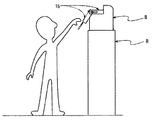
本体Aは、図1に示すように、本体Aの外観形状を形成させ各機能部を内装させる筐体1と、その筐体1の天面に設けられ画像記録された記録紙を排紙させる排紙部2と、画像記録前の記録紙を積重可能に収納させ単葉毎に記録紙を送り出す給紙部3と、その給紙部3と排紙部2とを結ぶように形成され記録紙が搬送される記録紙搬送路4と、給紙部3と排紙部2との間に設けられ画像データに基づいてトナー像を形成させるトナー像形成部5と、そのトナー像形成部5で形成されたトナー像を記録紙搬送路4上の記録紙へ転写させる転写部6と、その転写部6と排紙部2との間に設けられトナー像が転写された記録紙を加圧及び加熱させてトナー像を記録紙に定着させる定着部7と、転写部6と定着部7とを跨ぐように記録紙搬送路4と接続され記録紙を反転させる反転部8とを備えて構成されている。
Next, an embodiment of a support structure for a paper discharge tray according to the present invention will be described.
The paper discharge tray support structure according to the present embodiment is applied to a so-called top surface paper discharge type image forming apparatus. 1 to 9 show the first embodiment, FIGS. 10 to 15 show the second embodiment, FIGS. 16 to 21 show the third embodiment, and FIG. 22 shows the fourth embodiment. 23 shows the fifth embodiment, FIG. 24 shows the sixth embodiment, FIGS. 25 and 26 show the seventh embodiment, and FIGS. 27 to 30 show the eighth embodiment.
[First Embodiment]
First, an outline of the main body A (image forming apparatus) will be described before detailing the support structure of the paper discharge tray according to the first embodiment.
As shown in FIG. 1, the main body A discharges a
このように構成された本体Aは、画像データに基づいて形成したトナー像を記録紙に転写し、定着して、天面の排紙部2から排紙する、周知の工程でもって画像記録するようになっている。以下、本実施の形態にかかる排紙トレイの支持構造を詳述する。
第1の実施形態にかかる排紙トレイの支持構造は、上記した筐体1と、排紙トレイ9と、付勢手段10と、コロ部11と、延長トレイ12とを備えて構成されている。
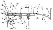
筐体1は、上記した各構成部が内装可能なように外観形状が略矩形体状に形成されると共に、平面視一辺側に形成された中段部1aと、中段部1aの一端側と隣接するように形成された上段部1bと、上段部1bと中段部1aとに隣接するように形成され、これらで2方を囲まれた下段部1cとで、天面側が螺旋階段状に形成されてなる。
このうち、上段部1bの下段部1c側壁面の中途部に上記した排紙部2が設けられ、その排紙部2の下に形成された下段部1cの底面が、後述する排紙トレイ9を略水平状に支承させる支承面Sになっている。
The main body A configured as described above transfers the toner image formed on the basis of the image data to the recording paper, fixes it, and ejects it from the
The discharge tray support structure according to the first embodiment includes the above-described
The
Among these, the
また、排紙部2の排紙方向の下段部1c縁部と排紙方向の縦壁面の上縁部との交差部が、所要角度でもって傾斜状に形成されて衝合部1dが構成され、その衝合部1dと平面視直交する方向のコーナー部に後述する排紙トレイ9を枢支させる一対の枢軸13が突設されている。
この一対の枢軸13は、図2に示すように、一方が排紙方向と平面視直交方向の縦壁面から外方へ向かって突設されると共に、他方がその枢軸13の軸線上の筐体1内部に突設されてなる。なお、後者の、筐体1内部に突設された枢軸と排紙トレイ9の軸受け部9eとを筐体1内で係合されるように、筐体1内の枢軸の真上となる支承面Sの一部が略矩形状に切欠されている(この切欠部と筐体内の枢軸は図示せず)。
排紙トレイ9は、図3に示すように、一方側(排紙部2側)が凸湾曲状に下方へ屈曲されると共に、他方側(回動中心側)が略水平状に形成され、支承面Sを被装可能な所要の大きさからなる略矩形状の天板9aと、その天板9aの周縁部に垂設された4つの側壁9b、9c、9d、9dと、他方側(回動中心側)の側壁9b及び一方側(排紙部2側)の側壁9cと平面視直交方向の両側壁9dの、他方側の側壁9b近傍の下部に設けられ、枢軸13に回動可能に係合された軸受け部9eと、その他方側の底部に設けられた底板9fとを備え、排紙部2の下方に配置されるように支承面Sに載置されている。
Further, an intersection portion between the
As shown in FIG. 2, one pair of the
As shown in FIG. 3, the
また、この排紙トレイ9は、天板9aの凸湾曲形状に略沿うように、両側壁9dが凸湾曲状に形成され、さらに、天板9aの凸湾曲側の終端が対向した一方側の側壁9cの中途部に位置するように、かつ、天板9aの水平側の終端が他方側の側壁9bの頂部と略面一または面一となるように設けられており、支承面Sに排紙トレイ9を載置させた際、記録紙を載置させるトレイ面Tとなる天板9aの上面と支承面Sとの間に空隙が形成されるようになっている。なお、この空隙部分に後述する出没機構が設けられている。
また、両側壁9dの凸湾曲側の終端上縁部は、図3に示すように、天板9aの凸湾曲状側の終端部よりも上位となるように、一方側(排紙部2側)の側壁9cと接続されて、天板9aの凸湾曲状側は、3方に側壁9c、9dが立設されるようになっている。このように排紙トレイ9の排紙部2側の上面を形成することで、トレイ面Tに記録紙が載置される際、記録紙の後部が確実に所定の位置に落下し、その記録紙が一方側(排紙部直下)で屈曲していくことで、自然に記録紙の幅方向を揃えることができる。
Further, the
Further, as shown in FIG. 3, the upper end edge on the convex curve side of both
また、他方側は側壁9b、9dとトレイ面Tとが略面一または面一にして記録紙の幅方向を規制しないから、トレイ面Tに記録紙が載置される際、記録紙の先部が側壁9bに引っ掛かる恐れもなくトレイ面Tにスムーズに摺動することができ、さらに、排紙が完了した際に、使用者が容易に記録紙を把持できるようになっている。
さらに、この排紙トレイ9は、底板9f上方の天板9a裏面がブロック状の肉厚部9gが形成されており、他方側の側壁9bとその肉厚部9gとを連通させたスリット状のガイド孔9hが形成されている。このガイド孔9hは、他方側の側壁9b側から見て、その側壁9b幅方向に向かって延出された水平部と、その水平部の中途部2箇所から上方へ向かって延出された垂直部からなる。なお、後述する延長トレイ12が、このガイド孔9hにスライド可能に遊嵌されるようになっている。
このように構成された排紙トレイ9は、軸受け部9eを介して筐体1に設けた枢軸13に枢支することで、その枢軸13を回動中心として回動し、底板9fが衝合部1dに衝合することで回動を規制して、トレイ面Tが排紙方向の縦壁面から下向き傾斜となるように、排紙部2の排紙方向で傾動するようになっている。
なお、この排紙トレイ9の傾斜角度は、トレイ面T上の記録紙が筐体1の外下方へ自然に滑落する程度の傾斜角度が好ましいが、当該画像形成装置の使用者が、少なくとも水平方向または下方向からトレイ面T上の記録紙を把持可能な角度であれば良いもので、特に限定されない(図8、図14参照)。
In addition, since the
Further, the
The
The inclination angle of the
付勢手段10は、図3に示すように、コイル部が枢軸13に遊挿され、アーム一端側が枢軸13より筐体1内方となる所要位置の縦壁面(排紙方向と平面視直交方向の壁面)に設けられた凸部に掛止されると共にアーム他端側が排紙トレイ9の底板9fに掛止されたねじりコイルバネからなり、排紙トレイ9をその衝合方向に付勢するようになっている。
このねじりコイルバネからなる付勢手段10のトルクは、衝合させて傾斜状態にした排紙トレイ9が緩やかな速度で支承面Sに向かう程度のトルクになっているが、排紙トレイ9の傾斜状態を維持するようなトルクにしても良い。この場合、排紙トレイ9が支承面Sに載置した状態を維持するためにフック(掛止部材)とピン(被掛止部材)等からなる掛止手段を設けることが好ましい。
コロ部11は、コロ11aと、出没機構と、を備えて構成されている。
コロ11aは、排紙トレイ9の傾動方向へ回動可能に排紙トレイ9に枢支された所要径の円盤状部材であり、後述する出没機構を介してトレイ面Tから出没可能なっている。また、このコロ11aは、図2に示すように、トレイ面Tに略矩形状となるように4つ配置されている。
As shown in FIG. 3, the urging means 10 has a vertical wall surface at a required position where the coil portion is loosely inserted into the
The torque of the biasing means 10 formed of the torsion coil spring is such that the
The roller unit 11 includes a
The
出没機構は、図2〜図4に示すように、スリット孔11bと、収納部11cと、軸受け11eと、弾性部材11fと、ボス11gと、リンク部とを備えてなる。
スリット孔11bは、コロ11aの外周面の一部をトレイ面Tから出没させる孔で、排紙トレイ9の回動方向に延出するように形成されると共に、トレイ面Tに略矩形状となるように4箇所に配設されている。
収納部11cは、トレイ面Tの裏面にそのスリット孔11bを取り囲むように垂設された箱状に形成されている。
また、この収納部11cは、横断平面視、略長方形状になっており、その長手方向の、一方の側壁の上部に収納部11cの内外を連通させた連通孔11dが設けられている。
軸受け11eは、箱状の収納部11c内に遊嵌可能に、平面視、略矩形状に形成されていると共に、短手方向の縦断面視、図4に示すように、略コ字状に形成され、その対峙した長手方向の側壁間の上部にコロ11aを枢支させてなる。このように構成された軸受け11eは、収納部11c内に上下動可能に遊嵌されている。
As shown in FIGS. 2 to 4, the retracting mechanism includes a
The
The
Further, the
The
弾性部材11fは、その軸受け11e内底面と収納部11cの外底面との間に張架された圧縮バネからなり、軸受け11eを上方へ付勢させるようになっている。
ボス11gは、連通孔11dと隣接するように、支承面Sから突設された所要長さの略棒状に形成されている。
リンク部は、ボス11gと連通孔11dとの間の天板9aの外底面から垂設された軸支部11hと、その軸支部11hに中途部が枢支され、一端が収納部11cに収納された軸受け11eの一方側の頂面と連通孔11dを介して係合可能に配置されると共に、他端がボス11gと係合可能に配置されてシーソー状に揺動可能に構成されたリンク11kとを備えてなる。
また、このリンク11kは、排紙トレイ9の非傾斜時(排紙トレイ9を支承面Sに載置した状態)、リンク11kの他端がボス11gと係合して時計方向へ回動すると同時に、リンク11kの一端で軸受け11eを押し下げてトレイ面Tからコロ11aが没するようになっている(図3、図4参照)。
排紙トレイ9の傾斜時は、リンク11kの他端がボス11gから離間して、軸受け11e内底面と収納部11cの外底面との間に張架した圧縮バネによって、軸受け11eがスリット孔11b周囲のトレイ面Tの裏面に当接するまで上昇すると同時にリンク11kが反時計方向へ回動してコロ11aの外周面の一部がトレイ面Tから突出するようになっている(図5、図6参照)。
The
The
The link portion has a
Further, the
When the
延長トレイ12は、ガイド孔9hの水平部にスライド可能に遊嵌された平板部12aと、その平板部12aの排紙トレイ9外方側の端部に、排紙トレイ9の他方側の側壁9bより上位となるように突設され、記録紙の滑落を防止させる略L字状の第1のストッパ12bと、平板部12aの排紙トレイ9内方側の端部に上方に向かって突設され、排紙トレイ9内に形成された肉厚部9gの側面に当接させて抜脱を防止させる第2のストッパ12cと、ガイド孔9hの垂直部にスライド可能に挿嵌され、第1のストッパ12b側の平板部12a上面から突設された一対の略扇状のリブ12dと、第1のストッパ12bの内側面に設けられ、記録紙の縁部を保護させる帯状の緩衝部材12eと、平板部12aの、一対のリブ12dよりトレイ幅方向外側に穿設され、線状の引っ張り部材(例えば組紐)を掛止させる掛止孔12fと、第1のストッパ12bの外側面に水平方向に突設された取手12gとを備えて構成され、排紙トレイ9の傾斜時において下側となるトレイ端部から出没可能になっている。
この延長トレイ12を設けることで、排紙トレイ9のトレイ面Tよりも大きいサイズの記録紙を載置することができる。
The
By providing the
また、一対の略扇状のリブ12dを設けることで、記録紙との摩擦が少なくなり(線接触のため)、記録紙がトレイ面Tを滑りやすくしている。したがって、例えば、トレイ面Tに複数枚の記録紙を積重させ、その状態で排紙トレイ9を傾斜させた場合、上部の記録紙がバラけて落ちることを防止でき、しかも、載置された記録紙を浮かすようにすることで、記録紙を容易に把持することができる。
なお、この延長トレイ12を設けない場合、排紙トレイ9の他方側の側壁9bを、トレイ面Tより上位となるように形成する。この場合においても、排紙トレイ9の他方側の側壁9bを第1のストッパ12bのように、頂部が内方へ屈曲した略L字状に形成し、その内側に緩衝部材12eを設け、外側に取手12gを設け、さらにトレイ面Tまたは他方側の側壁9bの上部に掛止孔12fを設けることが好適である。
Further, by providing the pair of substantially fan-shaped
When the
このように、第1の実施形態にかかる排紙トレイの支持構造は、記録紙を排紙する排紙部2の下に排紙トレイ9を載置する支承面Sを略水平状に設け、その支承面Sと排紙方向の縦壁面との交差部を所要角度でもって傾斜状に形成して衝合部1dを設け、排紙部2の排紙方向と平面視直交する方向に延出する一対の枢軸13を衝合部1d近傍に設け、その枢軸13に軸受け部9eを回動可能に係合して排紙トレイ9を筐体1に対して回動可能に、かつ、所要の回動角度で排紙トレイ9の底板9fが衝合部1dと衝合するように設け、アーム一端側を筐体1に係止すると共にアーム他端側を排紙トレイ9に係止しコイル部を枢軸13に遊挿したねじりコイルバネからなる付勢手段10を設けて、記録紙を載置するトレイ面Tが、排紙方向の縦壁面から下向き傾斜となるように、排紙トレイ9を傾動可能にした構造になっている。
加えて、第1の実施形態にかかる排紙トレイの支持構造は、排紙トレイ9の傾動方向側へ回動可能なコロ11aを、排紙トレイ9の傾斜時にトレイ面Tからコロ11aを突出すると共に排紙トレイ9の非傾斜時に排紙トレイ9にコロ11aを没入する出没機構を介して設け、排紙トレイ9のトレイ面Tを延長させる延長トレイ12を、排紙トレイ9の傾斜時において下側となるトレイ端部から出没可能に設けている。
As described above, the support structure of the discharge tray according to the first embodiment is provided with the support surface S on which the
In addition, the discharge tray support structure according to the first embodiment has a
次に、以上のように構成された第1の実施形態にかかる排紙トレイの支持構造を備えた画像形成装置の動作を説明する。なお、本体Aにおける作像プロセスは省略する。また、画像形成装置は図8に示すように机Dに載置しているものとする。
最初に、排紙トレイ9が支承面Sに載置している状態(第1の位置。通常この状態で画像形成を行う)を説明すると、出没機構を構成するリンク11kの他端が支承面Sから突設したボス11gと係合し、リンク11kの一端が軸受け11eを押し下げて、トレイ面Tからコロ11aが没している。なお、必要に応じて、延長トレイ12を引き出しておく。
本体A側で一連の作像プロセスが終了すると、排紙トレイ9より上方に設けた排紙部2から排紙が開始する。
まず、記録紙は、その先部がトレイ面Tに接し、そのトレイ面Tに沿うように排紙方向へ移動する。そして、排紙が完了すると同時に、記録紙の後部が自然落下してトレイ面Tに載置する。
このとき、コロ11aがトレイ面Tから突出していないころから、記録紙の先端部がトレイ面Tにスムーズに摺動する。また、緩衝部材12eが記録紙の縁部を保護する。
Next, the operation of the image forming apparatus having the discharge tray support structure according to the first embodiment configured as described above will be described. Note that the image forming process in the main body A is omitted. Further, it is assumed that the image forming apparatus is placed on a desk D as shown in FIG.
First, a state in which the
When a series of image forming processes is completed on the main body A side, paper discharge starts from the
First, the leading end of the recording paper is in contact with the tray surface T and moves in the paper discharge direction along the tray surface T. At the same time as the paper discharge is completed, the rear portion of the recording paper naturally falls and is placed on the tray surface T.
At this time, since the
2枚以上の排紙の場合、当然のことながら、トレイ面T上に既に載置している記録紙の上に積重するように、漸次、記録紙が載置していく。このとき、その記録紙が一方側で屈曲していくことで、自然に記録紙の幅方向が揃う。
所望数の記録紙がトレイ面Tに載置したら、使用者は、例えば延長トレイ12の取手12gを把持し下方へ押し下げることで、排紙トレイ9は枢軸13を中心に上方へ回動して所要の回動角度で排紙トレイ9の底板9fが衝合部1dと衝合する。
このとき、出没機構を構成するリンク11kの他端が支承面Sから突設したボス11gから離間して、軸受け11e内底面と収納部11cの外底面との間に張架した圧縮バネによって、軸受け11eがスリット孔11b周囲のトレイ面Tの裏面に当接するまで上昇すると同時にリンク11kが反時計方向へ回動してコロ11aの外周面の一部がトレイ面Tから突出する。
このようにして、記録紙を載置するトレイ面Tが、排紙方向の縦壁面から下向き傾斜したら(第2の位置)、使用者は、図8に示すように、本体Aの水平方向から記録紙を取り出す。このとき、コロ11aの外周面の一部がトレイ面Tから突出して、容易に取り出すことができる。
In the case of discharging two or more sheets, as a matter of course, the recording sheets are gradually placed so as to be stacked on the recording sheets already placed on the tray surface T. At this time, the recording paper is bent on one side, so that the width direction of the recording paper is naturally aligned.
When the desired number of recording papers are placed on the tray surface T, the user holds the
At this time, the other end of the
In this way, when the tray surface T on which the recording paper is placed is inclined downward from the vertical wall surface in the paper discharge direction ( second position ), the user can move from the horizontal direction of the main body A as shown in FIG. Remove the recording paper. At this time, a part of the outer peripheral surface of the
記録紙の取り出しが完了したら、使用者が取手12gなどから手を離すことで、ねじりコイルバネからなる付勢手段10によって、緩やかな速度で排紙トレイ9が支承面Sに向かって回動して初期位置に戻る。もちろん、使用者が強制的に排紙トレイ9を押し倒してもよい。
このとき、リンク11kの他端がボス11gと係合を開始して時計方向へ回動し、リンク11kの一端で軸受け11eを押し下げてトレイ面Tからコロ11aが没して、初期状態に戻る。
このように第1の実施形態にかかる排紙トレイの支持構造は、排紙トレイ9の非傾斜状態と傾斜状態の選択を可能にしたから、排紙トレイ9を非傾斜状態にすることで、排紙部2から排紙した記録紙をトレイ面Tに確実に載置でき、排紙トレイ9の傾斜状態にすることで、本体Aの水平方向や本体Aより下方から、記録紙を取り出すことができるようになっている。
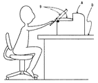
したがって、机D等の高所に画像形成装置を設置したとしても、排紙トレイ9を傾斜状態にすることで、例えば、使用者は立ち上がることなく、容易に記録紙を取り出すことができ、利便性を向上させている。
When the removal of the recording paper is completed, the user releases his / her hand from the
At this time, the other end of the
As described above, since the discharge tray support structure according to the first embodiment enables selection of the non-inclined state and the inclined state of the
Therefore, even if the image forming apparatus is installed at a high place such as the desk D, for example, the user can easily take out the recording paper without standing up by setting the
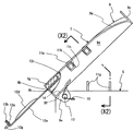
第1の実施形態にかかる排紙トレイの支持構造は、排紙トレイ9を排紙部2の排紙方向側に傾動されるように本体Aに支持されたものを例示したが、図9に示すように、排紙部2の排紙方向と平面視直交方向で傾動されるように、枢軸13と軸受け部9eを介して、排紙トレイ18を本体Aに支持させても良い。なお、図9に例示した排紙トレイ18の形状は、詳述した排紙トレイ9の形状(側壁と天面の形状)と若干異ならせたものを例示しているが、このように、排紙トレイ9の形状自体は、特に限定されるものではない。
また、第1の実施形態の動作説明では、例えば延長トレイ12の取手12gを把持し下方へ押し下げることを例示したが、掛止孔12fに組紐などを挿通しておき、その組紐を下方へ引っ張って排紙トレイ9を回動しても良い。
The discharge tray support structure according to the first embodiment is exemplified by the
In the explanation of the operation of the first embodiment, for example, the
[第2の実施形態]
次に、第2の実施形態にかかる排紙トレイの支持構造を、図10〜図15を参照しながら説明する。なお、本体B(画像形成装置)の画像形成にかかる構成は、第1の実施形態と同一であるため、その説明は省略する。
第2の実施形態にかかる排紙トレイの支持構造は、筐体14と、排紙トレイ15と、係合手段と、引っ張り手段17と、コロ11aと、延長トレイ12とを備えて構成されている。
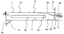
筐体14は、画像形成にかかる各機能部が内装可能なように外観形状が略矩形体状に形成されると共に、平面視一辺側に形成された中段部14aと、中段部14aの一端側と隣接するように形成された上段部14bと、中段部14aと対向するように形成された第2中段部14cと、上段部14bと中段部14aと第2中段部14cとに隣接するように、かつ、排紙方向の縦壁面から本体B内方へ延出するように凹状に形成された収納凹部14dとで、天面側が凹凸状に形成されてなる。この収納凹部14dは、排紙トレイ15を収納させるもので、その底面が、後述する排紙トレイ15を略水平状に支承させる支承面Sになっている。
[Second Embodiment]
Next, a paper discharge tray support structure according to the second embodiment will be described with reference to FIGS. Note that the configuration related to image formation of the main body B (image forming apparatus) is the same as that in the first embodiment, and thus the description thereof is omitted.
The discharge tray support structure according to the second embodiment includes a
The
また、上段部14bの収納凹部14d側壁面の中途部に排紙部2が設けられている。さらに、この排紙部2の排紙方向の収納凹部14d縁部と排紙方向の縦壁面の上縁部との交差部が、所要角度でもって傾斜状に形成されて衝合部14eが構成され、中段部14aと第2中段部14cの縦壁面に排紙方向に向かって所要長さに延出された長孔からなる係合部14fが設けられている。なお、この係合部14fは、長孔に替えて長溝(内壁面に設ける)でも良い。
また、図11に示すように、衝合部14eの傾斜角度でもって側面視略V字状に形成された板バネからなる弾性部材16が、支承面Sと面一となるように衝合部14eに止着されている。
この板バネからなる弾性部材16のトルクは、衝合させて傾斜状態にした排紙トレイ15(後述する)が緩やかな速度で水平状に戻る程度のトルク、または、後述する引っ張り手段17とで緩やかな速度で水平状に戻る程度のトルクになっている。なお、傾斜状態の排紙トレイ15に弱い力を付与するだけで軽快に浮き上がるようなトルクや、単純な緩衝機能としてのトルク(勢い良く傾斜されるのを防止(破損防止))にしても良い。また、機敏に動作するような速度でも良い。この場合、各当接面に、緩衝部材を止着しておくことが好ましい。
Further, the
Further, as shown in FIG. 11, the abutting portion is formed so that the
The torque of the
また本実施の形態では、弾性部材16として板バネを例示しているが、合成樹脂材、ゴムなど復元力を有する部材であれば特に限定されない。
排紙トレイ15は、図10〜図13に示すように、第1の実施形態で例示した排紙トレイ15と基本的に形状が同じであり、共通する構成部は説明を省略し、異なる構成部である、被係合部15aを詳述する。
被係合部15aは、天板の凸湾曲形状に略沿うように凸湾曲状に形成された両側壁15b(排紙トレイ15の)の排紙部2側から外方へ向かって突設され、長孔からなる係合部14fに遊嵌された枢軸からなる。
この被係合部15aと上記した係合部14fとで係合手段が構成されており、排紙トレイ15と本体Bとが、この係合手段を介して接続されることで、収納凹部14dに収納された排紙トレイ15が排紙方向の縦壁面から突出可能になっていると共に、その縦壁面から突出された排紙トレイ15が被係合部15aを回動中心にして、下方に向かって回動可能になっている。また、この排紙トレイ15は、底板15eが衝合部14eに衝合されることで、トレイ面Tが排紙方向の縦壁面から下向き傾斜となるように、排紙部2の排紙方向で傾動されるようになっている。
Moreover, in this Embodiment, although the leaf | plate spring is illustrated as the
As shown in FIGS. 10 to 13, the
The engaged
The engaged
引っ張り手段17は、排紙部2直下の上段部14b側壁に設けた開口部14gを介して一端が筐体14内に係止され、他端が排紙トレイ15の一方側(排紙部2側)の側壁15cに係止された引っ張りバネからなり、排紙方向の縦壁面から突出された排紙トレイ15を本体Bの内方側へ引っ張るようになっている。
この引っ張り力は、排紙トレイ15が緩やかな速度で初期位置に戻る程度の力になっているが、排紙トレイ15に弱い力を付与するだけで軽快に初期位置に戻るような力に設定にしても良い。また、単純な緩衝機能(勢い良く引き出されないため(破損防止))にしても良い。また、排紙トレイ15が機敏に動作(引き戻される)するような引っ張り力でも良い。この場合、各当接面に、緩衝部材を止着しておくことが好ましい。なお、この板バネに替えて、周知構造の巻き取り機構を筐体14内に内装し、その巻き取り機構に接続されたワイヤなどの線状部材を側壁15cに係止させても良い。
なお、この引っ張り手段17は、排紙方向の縦壁面から水平状に突出された排紙トレイ15を収納凹部14dに引き戻すものであり、弾性部材16は、傾斜状態の排紙トレイ15を水平状へ戻すものであるが、引っ張り手段17は、傾斜状態の排紙トレイ15を水平状へ戻す作用を兼ねている。
One end of the pulling
This pulling force is such a force that the
The pulling means 17 pulls the
コロ11aは、トレイ面Tから突出されるように、排紙トレイ15の傾動方向側へ回動可能なコロ11aがトレイ面Tの裏面側に枢着されてなる。なお、このコロ11aは、第1の実施形態で例示した出没機構を介して取り付けられていないが、第1の実施形態と同様に出没機構を介して取り付けても良い。この場合、排紙トレイ15が水平方向にスライドするとした本実施の形態では、スライド時、リンクと支承面Sから突設されたボスとが干渉してしまうため、第1の実施形態で例示した出没機構をそのまま適用することはできないが、しかしながら、例えば、ボスに替えて、スライド方向に延設されカム面を傾斜状にした板カムにし、リンクの他端に、その板カムと係合するカムフォロアを設けることで、スライド動作に対応した出没機構を構成することができる。
延長トレイ12は、第1の実施形態で例示した排紙トレイ15と構成が同じであり、同一符号を付して説明を省略する。
このように、第2の実施形態にかかる排紙トレイの支持構造は、記録紙を排紙する排紙部2の下に排紙トレイ15を略水平状の載置して収納する収納凹部14dを設け、その支承面Sと排紙方向の縦壁面との交差部を所要角度でもって傾斜状に形成して衝合部14eを設け、長孔からなる係合部14fを収納凹部14dの壁面に排紙トレイ15のスライド方向に延出するように設け、枢軸からなる被係合部15aを排紙トレイ15の外面から突出するように設け、その被係合部15aに係合部14fを係合して、排紙トレイ15を筐体14に対してスライド(引き出し)可能及び回動可能に、かつ、所要の回動角度で排紙トレイ15の底板15eが弾性部材16を挟んで衝合部14eと衝合するように設け、排紙方向の縦壁面から突出した排紙トレイ15を本体Bの内方側へ引っ張るように引っ張りバネからなる引っ張り手段17を設けて、記録紙を載置するトレイ面Tが、排紙方向の縦壁面から下向き傾斜となるように、排紙トレイ15を傾動可能にした構造になっている。
The
The
As described above, the discharge tray support structure according to the second embodiment has the
次に、以上のように構成された第2の実施形態にかかる排紙トレイの支持構造を備えた画像形成装置の動作を説明する。なお、本体Bにおける作像プロセスは省略する。また、画像形成装置は図14に示すようにラックR上に載置しているものとし、必要に応じて、延長トレイ12を引き出しておくものとする。
本体B側で一連の作像プロセスが終了すると、排紙トレイ15より上方に設けた排紙部2から排紙が開始する。
まず、記録紙は、その先部がトレイ面Tに接し、そのトレイ面Tに沿うように排紙方向へ移動する。そして、排紙が完了すると同時に、記録紙の後部が自然落下してトレイ面Tに載置する。
所望数の記録紙がトレイ面Tに載置したら、使用者は、例えば延長トレイ12の取手を把持して排紙トレイ15を手前に引き、排紙方向の縦壁面から突出した排紙トレイ15を下方に向かって押し下げることで、排紙トレイ15は枢軸からなる被係合部15aを中心に上方へ回動し、所要の回動角度で排紙トレイ15の底板15eが衝合部14eと衝合する。
このようにして、記録紙を載置するトレイ面Tが、排紙方向の縦壁面から下向き傾斜したら(第2の位置)、使用者は、図14に示すように、本体Bの下方から記録紙を取り出す。
Next, the operation of the image forming apparatus including the discharge tray support structure according to the second embodiment configured as described above will be described. Note that the image forming process in the main body B is omitted. Further, it is assumed that the image forming apparatus is placed on the rack R as shown in FIG. 14, and the
When a series of image forming processes is completed on the main body B side, paper discharge starts from the
First, the leading end of the recording paper is in contact with the tray surface T and moves in the paper discharge direction along the tray surface T. At the same time as the paper discharge is completed, the rear portion of the recording paper naturally falls and is placed on the tray surface T.
When the desired number of recording sheets is placed on the tray surface T, the user holds the handle of the
In this way, when the tray surface T on which the recording paper is placed is inclined downward from the vertical wall surface in the paper discharge direction (second position) , the user can record from below the main body B as shown in FIG. Remove the paper.
記録紙の取り出しが完了したら、使用者が取手などから手を離すことで、弾性部材16及び引っ張り手段17によって、緩やかな速度で排紙トレイ15が水平状に戻り、引っ張り手段17によって収納凹部14dに緩やかな速度で引き戻されて初期位置に戻る(第1の位置)。このように、使用者が取手などから手を離すだけ(ワンアクション)で、排紙トレイ15は初期位置に戻ることから、極めてユーザーフレンドリィな構造になっている。もちろん、使用者が強制的に排紙トレイ15を収納凹部14dに戻しても良い。
このように第2の実施形態にかかる排紙トレイの支持構造は、排紙トレイ15の非傾斜状態と傾斜状態の選択を可能にしたから、排紙トレイ15を非傾斜状態にすることで、排紙部2から排紙した記録紙をトレイ面Tに確実に載置でき、排紙トレイ15の傾斜状態にすることで、本体Bの水平方向や本体Bより下方から、記録紙を取り出すことができるようになっている。
したがって、ラックR等の高所に画像形成装置を設置したとしても、排紙トレイ15を傾斜状態にすることで、画像形成装置の下方から、容易に記録紙を取り出すことができ、利便性を向上させている。
When the removal of the recording paper is completed, the user removes his / her hand from the handle and the like, whereby the
As described above, since the discharge tray support structure according to the second embodiment enables selection of the non-inclined state and the inclined state of the
Therefore, even if the image forming apparatus is installed at a high place such as the rack R, the recording paper can be easily taken out from the lower side of the image forming apparatus by setting the
なお、第2の実施形態にかかる排紙トレイの支持構造は、排紙トレイ15を排紙部2の排紙方向側に傾動されるように本体Bに支持されたものを例示したが、図15に示すように、排紙部2の排紙方向と平面視直交方向で傾動されるように、係合部14fと被係合部15aを介して、排紙トレイ19を本体Bに支持させても良い。なお、図15に例示した排紙トレイ15の形状は、詳述した排紙トレイ15の形状(側壁15b、15cと天面の形状)と若干異ならせたものを例示しているが、このように、排紙トレイ15の形状自体は、特に限定されるものではない。
以上、本実施の形態を説明したが、上述した実施の形態は、本発明の好適な実施の形態の一例を示すものであり、本発明はそれに限定されるものではなく、その要旨を逸脱しない範囲内において、種々変形実施が可能である。
また、本実施の形態では、排紙トレイの支持構造を例示したが、この上記した排紙トレイの支持構造を備えた画像形成装置でも良い。画像形成装置の例として、例えば、ファクシミリ、MFP(マルチファンクションプリンター)、複写機、プリンター等が挙げられる。この場合の排紙トレイの支持構造は、排紙部2の配設位置(本体Bの天面または胴内)に応じて配設される。
In addition, although the discharge tray support structure according to the second embodiment is illustrated as being supported by the main body B so that the
Although the present embodiment has been described above, the above-described embodiment shows an example of a preferred embodiment of the present invention, and the present invention is not limited thereto and does not depart from the gist thereof. Various modifications can be made within the range.
In the present exemplary embodiment, the support structure for the paper discharge tray is illustrated, but an image forming apparatus including the support structure for the paper discharge tray described above may be used. Examples of the image forming apparatus include a facsimile, an MFP (multifunction printer), a copier, a printer, and the like. In this case, the support structure of the paper discharge tray is arranged according to the arrangement position of the paper discharge unit 2 (the top surface or the body of the main body B).
[第3の実施形態]
次に、第3の実施形態として、第1、第2の実施形態における排紙トレイの支持構造を備えた画像形成装置について、図16を用いて説明する。
本実施形態にかかる画像形成装置本体の下段部1cの適所には、トレイセンサ101として透過型フォトインタラプタが設置されている。そして、排紙トレイ9の下部にはリブ102が設けられている。
排紙トレイ9が支承面Sに載置している状態(以下「初期状態」という)にあるときには、リブ102がフォトインタラプタの発光素子と受光素子間を遮断している。しかし、排紙トレイ9が持ち上がると、リブ102も持ち上がり、排紙トレイ9が初期状態にないことが検出される。
なお、排紙トレイ9が持ち上がったことが検出されればよいので、トレイセンサ101は本例のような光学センサに限らず、メカニカルスイッチ等を利用することもできる。
[Third Embodiment]
Next, as a third embodiment, an image forming apparatus provided with a discharge tray support structure in the first and second embodiments will be described with reference to FIG.
A transmissive photo interrupter is installed as a tray sensor 101 at an appropriate position of the
When the
Note that the tray sensor 101 is not limited to the optical sensor as in the present example, and a mechanical switch or the like can be used because it is only necessary to detect that the
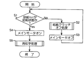
図17のフローは、トレイセンサ101を有する画像形成装置の動作を示したものである。
画像形成装置が印刷ジョブを受信すると、画像形成装置は排紙トレイ9が初期状態にあるか否かをトレイセンサ101によって検出する(S1)。排紙トレイ9が初期状態にないときは、給紙クラッチオフ処理(S2)を実行した後、或いは給紙クラッチ処理を行うことなく、画像形成装置のメインモータへの通電を停止し、画像形成装置の動作を一時停止する(S3)。
一方、排紙トレイ9が初期状態にあるときは、画像形成装置のメインモータへの通電を継続し(S4)。場合によっては再印字処理を実行する(S5)。これにより、排紙トレイ9を動かしたときには、印刷動作が一時停止され、排紙用紙のスタック不良危険性を減少させることができる。なお、再印字処理については後述する。
図18は給紙クラッチオフ処理(S2)の動作フローを示したものである。
この処理では、搬送経路内に記録紙が存在するか否かを、搬送経路内に設けられたセンサによって検出する(S201)。搬送経路内に記録紙が存在すると判別したときは、給紙クラッチをオフにして給紙動作を一時停止し(S202)、搬送中の記録紙を排出する。このような処理はステップS201において搬送経路内に記録紙が無いと判別するまで行う。
The flow in FIG. 17 shows the operation of the image forming apparatus having the tray sensor 101.
When the image forming apparatus receives a print job, the image forming apparatus detects whether or not the
On the other hand, when the
FIG. 18 shows an operation flow of the paper feed clutch off process (S2).
In this process, whether or not a recording sheet is present in the transport path is detected by a sensor provided in the transport path (S201). If it is determined that there is recording paper in the transport path, the paper feed clutch is turned off to temporarily stop the paper feed operation (S202), and the transporting recording paper is discharged. Such processing is performed until it is determined in step S201 that there is no recording paper in the transport path.
図19は給紙クラッチオフ処理(S2)の他の動作フローを示したものである。
この処理では、搬送経路内に記録紙が存在するか否かを、搬送経路内に設けられたセンサによって検出する(S211)。搬送経路内に記録紙が存在すると判別したときは、残印字情報をメモリに一時保存し(S212)、搬送中の記録紙には印字せずに排出する(S213)。この後、給紙クラッチをオフにして(S214)。このような処理はステップS201において搬送経路内に記録紙が無いと判別されるまで行う。
上記処理を実行後は、画像形成装置のメインモータへの通電を停止し(図17、S3)、画像形成装置の動作を一時停止する。そして、排紙トレイ9が初期状態に戻ったときには、メインモータへの通電を再開し(S4)、再印字処理を実行する。
FIG. 19 shows another operation flow of the paper feed clutch off process (S2).
In this process, whether or not a recording sheet is present in the transport path is detected by a sensor provided in the transport path (S211). When it is determined that there is a recording sheet in the transport path, the remaining print information is temporarily stored in the memory (S212), and discharged without printing on the recording sheet being transported (S213). Thereafter, the paper feed clutch is turned off (S214). Such processing is performed until it is determined in step S201 that there is no recording paper in the transport path.
After executing the above processing, the power supply to the main motor of the image forming apparatus is stopped (S3 in FIG. 17), and the operation of the image forming apparatus is temporarily stopped. When the
図20は、再印字処理の動作フローを示したものである。
再印字処理では、給紙クラッチをオンにし(S501)、一時保存した残印字情報をメモリから呼び出して印字を行う(S502)。
また、給紙クラッチオフ処理(S2)は、次のようなものであってもよい。
図21は給紙クラッチオフ処理(S2)の動作フローを示したものである。
この処置では、搬送経路内に記録紙が存在するか否かを、搬送経路内に設けられたセンサによって検出する(S221)。搬送経路内に記録紙が存在するときは、残印字情報をメモリに一時保存し(S222)、例えば、画像形成装置の使用者が装置を操作するためのオペレーションパネルに「排紙トレイが下がっています」との表示を行い(S223)、「印字の途中です」と印字した紙を排出する(S224)。この後、給紙クラッチをオフにする(S225)。以降の動作は、先に述べた通りであり、排紙トレイ9が初期状態に戻ったときには、メインモータへの通電を再開し(S4)、再印字処理を実行する。
FIG. 20 shows an operation flow of the reprinting process.
In the reprinting process, the paper feed clutch is turned on (S501), and the temporarily stored remaining print information is called from the memory to perform printing (S502).
Further, the paper feed clutch off process (S2) may be as follows.
FIG. 21 shows an operation flow of the paper feed clutch off process (S2).
In this procedure, whether or not a recording sheet is present in the transport path is detected by a sensor provided in the transport path (S221). When there is a recording sheet in the transport path, the remaining print information is temporarily stored in the memory (S222). For example, the user can use the image forming apparatus on the operation panel for operating the apparatus. Is displayed (S223), and the paper on which “printing is in progress” is discharged (S224). Thereafter, the paper feed clutch is turned off (S225). The subsequent operation is as described above. When the
[第4の実施形態]
次に、第4の実施形態として、第1、第2の実施形態における排紙トレイの支持構造を備えた画像形成装置について説明する。
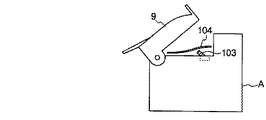
図22の画像形成装置は、本体の下段部1cの適所に排出紙の有無を確認できる排出紙センサ103を取り付けたものである。このセンサは、例えば排出紙の重量により押される機械的な押しボタンスイッチや、光の反射を利用したフォトリフレクタ等を利用することができる。このセンサを取り付けることにより、排紙トレイ9が初期状態にないときに、記録紙が排出されたことを検知することができる。
排紙トレイ9の下部に記録紙が存在すると、排紙トレイ9が正常な位置にセットされず、排紙スタック不良を起こす可能性がある。排出紙センサ103で記録紙の存在を検出した場合には、使用者に対して、オペレーションパネルによるメッセージの表示や、警告音などにより排出紙の除去を喚起することができ、排紙スタック不良を起こす可能性を低減させることができる。
[Fourth Embodiment]
Next, as a fourth embodiment, an image forming apparatus provided with a discharge tray support structure in the first and second embodiments will be described.
The image forming apparatus of FIG. 22 has a
If recording paper is present at the bottom of the
[第5の実施形態]
次に、第5の実施形態として、本発明の排紙トレイの支持構造を備えた画像形成装置に排紙トレイのロック機構を取り付けたものについて、図23に基づいて説明する。
排紙トレイ9の下部の支承面Sに対向する部分の適所にはシャフト105が設置されており、画像形成装置本体には略逆L字状のロック爪106が設置され、ロック爪106はシャフト105に掛止可能な構成となっている。ロック爪106の台座には、その中央に突設して軸107が設けられ、台座の本体排紙部側はロック爪用ソレノイド108と接続され、他方はコイルばね109と接続されている。
また、本体の支承面Sより下部であって、排紙方向と平面視直行方向の縦壁面に、排紙方向と平面視直行方向に軸107と係合するようにスライド穴110が設けられ、ロック爪106は排紙方向と平面視直行方向に移動する。
[Fifth Embodiment]
Next, as a fifth embodiment, an image forming apparatus equipped with a discharge tray support structure according to the present invention, to which a discharge tray lock mechanism is attached, will be described with reference to FIG.
A
In addition, a
ロック爪106は、コイルばね109の復元力によって本体排紙部と反対方向に移動することでシャフトから離れ、排紙トレイ9のロックが解除される。そうすると、排紙トレイ9を自由に移動させることができる。また、ロック爪106がソレノイド108の吸引力によって本体排紙部側に移動することで、ロック爪106がシャフト105に掛止され、排紙トレイ9を初期状態に固定することができる。
このような構成とすることで、印字動作中は排紙トレイ9を初期状態に固定しておくことができるようになり、印字動作中に誤って排紙トレイ9が動かされることがない。したがって、排紙トレイ9と下段部1cとの間に記録紙が排出されることがないから、排紙トレイを必ず正常な位置にセットすることができ、排紙スタック不良を防止することができる。
また、このような構成を有する画像形成装置について、排紙トレイ9を印字動作中に固定しておくか、あるいは固定を解除しておくかということを使用状況に応じて自由に設定できるようにすれば、使用者のニーズに合ったさらに使いやすい画像形成装置を提供できる。
The
With such a configuration, the
Further, in the image forming apparatus having such a configuration, whether the
[第6の実施形態]
次に、第6の実施形態として、本発明の排紙トレイの支持構造を備えた画像形成装置に排紙トレイ9自動昇降機能を備えたものについて、図24に基づいて説明する。
排紙トレイ9の回転支点である枢軸13には付勢手段10が設けられ、トレイを開く方向に力がかかっている。
また画像形成装置本体側には、排紙トレイ9上昇用ソレノイド111が設けられている。上昇用ソレノイド111の引張り部分は排紙トレイ9に接続されており、上昇用ソレノイド111のオン/オフにより排紙トレイ9が上昇又は下降できる構成となっている。
また、延長トレイ12には、延長トレイ用ソレノイド112と付勢手段113(本例ではコイルばね)が設けられ、延長トレイ用ソレノイド112のオン/オフにより延長トレイ12が稼動できる構成となっている。
このような構成とすることにより、排紙トレイ9及び延長トレイ12を自動で動かすことができ、使用者が自らトレイを出し入れする手間を省くことができる。
[Sixth Embodiment]
Next, as a sixth embodiment, an image forming apparatus provided with a discharge tray support structure according to the present invention and provided with a
A biasing means 10 is provided on the
A
Further, the
By adopting such a configuration, the
[第7実施形態]
本実施形態では、第6の実施形態における画像形成装置にトレイ稼動用のスイッチを設けた。以下、図25、図26に基づいて説明する。
図25の画像形成装置は、排紙トレイ9が排紙部2の排紙方向側に傾動されるように本体Aに支持されており、本実施例では本体前面下部にトレイ稼動用のスイッチ114を設けた例である。また、図26の画像形成装置は、排紙トレイ18を排紙部2の排紙方向と平面視直交方向で傾動されるように本体Aに支持されており、本実施例では本体側面下部にトレイ稼動用のスイッチ114を設けた例である。
トレイ稼動用のスイッチを設けることにより、スイッチ一つで素早くトレイの出し入れをすることが可能となる。また、トレイ稼動用のスイッチを本体下部に設けることで、画像形成装置が高所に設置された場合でもスイッチを押しやすくしている。さらに、排紙トレイの形状に合わせてスイッチの設置位置を変えることで、使い勝手の良い画像形成装置を提供することができる。
[Seventh Embodiment]
In the present embodiment, a switch for operating the tray is provided in the image forming apparatus in the sixth embodiment. Hereinafter, a description will be given based on FIGS. 25 and 26.
The image forming apparatus shown in FIG. 25 is supported by the main body A so that the
By providing a switch for operating the tray, it is possible to quickly insert and remove the tray with a single switch. Further, by providing a switch for operating the tray at the lower part of the main body, it is easy to press the switch even when the image forming apparatus is installed at a high place. Furthermore, an easy-to-use image forming apparatus can be provided by changing the installation position of the switch according to the shape of the paper discharge tray.
[第8実施形態]
次に、第8の実施形態として、第7の実施形態における画像形成装置のトレイ稼動用のスイッチが押されたときの動作について、図27を用いて説明する。
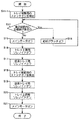
トレイ稼動用のスイッチオンが検出されると(S11−1)、搬送経路内に記録紙が存在するか否かを、搬送経路内に設けられたセンサによって検出する(S12)。搬送経路内に記録紙が存在するときは、メモリ内の全ての印刷ジョブを終了させた後(S13−1)、給紙クラッチをオフにして給紙動作を一時停止し(S14)、搬送中の記録紙を排出する。画像形成装置のメインモータへの通電を停止し(S15)、トレイ上昇用ソレノイドをオフにし、排紙トレイ9を上昇させ(S16)、延長トレイ用ソレノイドをオフにし、延長トレイを射出する(S17)。トレイ稼動用のスイッチオフが検出されると(S18)、延長トレイ用ソレノイドをオンにし、延長トレイ元に戻し(S19)、トレイ上昇用ソレノイドをオンにし、排紙トレイ9を下降させ(S20)、画像形成装置のメインモータへの通電を再開する(S21)。
これにより、印字動作中にスイッチが押されても、印刷ジョブが終了した後にトレイが動くので、ジャムやスタック不良の原因を低減させることができる。
[Eighth Embodiment]
Next, as an eighth embodiment, an operation when the tray operation switch of the image forming apparatus in the seventh embodiment is pressed will be described with reference to FIG.
When switch-on for tray operation is detected (S11-1), it is detected by a sensor provided in the transport path whether or not recording paper is present in the transport path (S12). If there is recording paper in the transport path, after all print jobs in the memory are finished (S13-1), the paper feed clutch is turned off to temporarily stop the paper feed operation (S14), and the transport is in progress. Eject the recording paper. The energization to the main motor of the image forming apparatus is stopped (S15), the tray raising solenoid is turned off, the
As a result, even if the switch is pressed during the printing operation, the tray moves after the print job is completed, so that it is possible to reduce the cause of jamming or stacking failure.
図28は、第7の実施形態における画像形成装置のトレイ稼動用のスイッチが押されたときの他の動作フローである。なお、図27と同一ステップには同一符号を付して説明は省略する。図28に示す動作フローでは、上記図27に示したステップS13−1の「メモリ内の全ての印刷ジョブを終了させる」代わりに、ステップS13―2として「印字中の印刷ジョブを終了」させた後に、S14〜S21の制御を行えば、数多くの印刷ジョブがあるときでも、トレイの下降までに要する時間を低減させることができ、効率よく印字作業ができるようになる。
図29は、第7の実施形態における画像形成装置のトレイ稼動用のスイッチが押されたときのさらに他の動作フローである。なお、図27と同一ステップには同一符号を付して説明は省略する。図29に示す動作フローでは、上記図27、図28に示したステップS13を踏まずに給紙動作を一時停止する制御を行うようにしている。このようにすれば、搬送経路内にある記録紙のみを印字して排出した後に、排紙トレイを下降させることができるので、ボリュームのある印刷ジョブがあるときでも、トレイの下降までに要する時間を低減させることができ、効率よく印字作業ができるようになる。
なお、図27〜図29の制御を操作者が自由に設定できるようにすれば、さらに使い勝手の良い画像形成装置を提供できる。
図30は、第7の実施形態における画像形成装置のトレイ稼動用のスイッチが押されたときのさらに他の動作フローである。図30に示す動作フローでは、画像形成装置に排紙トレイ満杯検知センサを設け、ステップS11−2において「排紙トレイ満杯を検出」したときに、S14〜S21の制御を行うようにしている。このようにすれば、満杯検知センサが働いた後の、排紙トレイを下ろす手間が削減できる。
FIG. 28 is another operation flow when the tray operation switch of the image forming apparatus according to the seventh embodiment is pressed. The same steps as those in FIG. 27 are denoted by the same reference numerals and description thereof is omitted. In the operation flow shown in FIG. 28, instead of “end all print jobs in the memory” in step S13-1 shown in FIG. 27, “end print job being printed” is ended as step S13-2. If the control of S14 to S21 is performed later, even when there are many print jobs, the time required to lower the tray can be reduced, and the printing operation can be performed efficiently.
FIG. 29 shows still another operation flow when the tray operation switch of the image forming apparatus in the seventh embodiment is pressed. The same steps as those in FIG. 27 are denoted by the same reference numerals and description thereof is omitted. In the operation flow shown in FIG. 29, control for temporarily stopping the paper feeding operation is performed without step S13 shown in FIGS. In this way, it is possible to lower the paper discharge tray after printing and discharging only the recording paper in the transport path, so even when there is a volume print job, the time required for the tray to lower Can be reduced, and printing can be performed efficiently.
If the control of FIGS. 27 to 29 can be freely set by the operator, a more convenient image forming apparatus can be provided.
FIG. 30 is still another operation flow when the switch for operating the tray of the image forming apparatus according to the seventh embodiment is pressed. In the operation flow shown in FIG. 30, a discharge tray full detection sensor is provided in the image forming apparatus, and the control of S14 to S21 is performed when “discharge tray full detection” is detected in step S11-2. In this way, it is possible to reduce the trouble of lowering the discharge tray after the full detection sensor is activated.
A、B…本体、1…筐体、1d、14e…衝合部、2…排紙部、9、15、18、19…排紙トレイ、9f、15e…底板、10…付勢手段、11a…コロ、11b…スリット孔、11c…収納部、11d…連通孔、11e…軸受け、11f…弾性部材、11g…ボス、11h…軸支部、11k…リンク、12…延長トレイ、12d…リブ、12e…緩衝部材、12f…掛止孔、12g…取手、13…枢軸、14d…収納凹部、14f…係合部、15a…被係合部、16…弾性部材、17…引っ張り手段、S…支承面、T…トレイ面、101…トレイセンサ、102…リブ、103…排出紙センサ、105…シャフト、106…ロック爪、107…軸、108…ロック爪用ソレノイド、110…スライド穴、111…上昇用ソレノイド、112…延長トレイ用ソレノイド、113…付勢手段、114…トレイ稼動用スイッチ A, B ... main body, 1 ... housing, 1d, 14e ... abutting part, 2 ... paper discharge part, 9, 15, 18, 19 ... paper discharge tray, 9f, 15e ... bottom plate, 10 ... biasing means, 11a ... roller, 11b ... slit hole, 11c ... storage part, 11d ... communication hole, 11e ... bearing, 11f ... elastic member, 11g ... boss, 11h ... shaft support, 11k ... link, 12 ... extension tray, 12d ... rib, 12e ... buffer member, 12f ... retaining hole, 12g ... handle, 13 ... pivot, 14d ... storage recess, 14f ... engaging part, 15a ... engaged part, 16 ... elastic member, 17 ... pulling means, S ... bearing surface , T ... tray surface, 101 ... tray sensor, 102 ... rib, 103 ... discharged paper sensor, 105 ... shaft, 106 ... lock claw, 107 ... shaft, 108 ... solenoid for lock claw, 110 ... slide hole, 111 ... for lifting Solenoid, 11 ... extension tray solenoid, 113 ... biasing means, 114 ... tray operation switch
Claims (13)
前記排紙トレイは、前記画像形成部により画像形成されて排出された前記記録紙を載置させるトレイ面と、該トレイ面に記録紙が載置される第1の位置と前記トレイ面を下方に傾斜させて前記トレイ面上の記録紙を取り出すための第2の位置との間で前記トレイ面を移動させる移動機構と、を備え、
前記排紙トレイが前記第2の位置のとき、少なくとも前記トレイ面の前記記録紙排出方向下流側端部が、前記画像形成装置本体の側面よりも突出し、且つ該画像形成装置本体の上面よりも下方に位置し、
前記排紙トレイには、前記トレイ面から突出されるように、前記排紙トレイの傾動方向側へ回動可能なコロが枢着され、該コロは、前記支承面と前記排紙トレイとの係合に連係されて、前記排紙トレイが前記第2の位置にあるときに前記トレイ面から突出されると共に前記排紙トレイが前記第1の位置にあるときに該排紙トレイに没入される出没機構を介して前記排紙トレイに設けられていることを特徴とする排紙トレイの支持構造。 A paper discharge tray that is supported on the upper surface of an image forming apparatus main body provided with an image forming section for forming an image on recording paper and on which recording paper discharged from a paper discharge section provided in the image forming apparatus main body is placed. A support structure,
The paper discharge tray has a tray surface on which the recording paper formed and discharged by the image forming unit is placed, a first position where the recording paper is placed on the tray surface, and the tray surface below And a moving mechanism for moving the tray surface between a second position for taking out the recording paper on the tray surface by inclining,
When the paper discharge tray is in the second position, at least the downstream end of the tray surface in the recording paper discharge direction protrudes from the side surface of the image forming apparatus main body and is higher than the upper surface of the image forming apparatus main body. Located below ,
The discharge tray is pivotally attached with a roller that can rotate in a tilting direction of the discharge tray so as to protrude from the tray surface, and the roller is connected to the support surface and the discharge tray. Linked to the engagement, the discharge tray protrudes from the tray surface when the discharge tray is in the second position, and is immersed in the discharge tray when the discharge tray is in the first position. A support structure for the paper discharge tray, which is provided on the paper discharge tray via a retracting mechanism .
前記排紙トレイは、前記支承面から上方に向かって回動可能に、かつ、所要の回動角度でもって前記画像形成装置本体に衝合可能に枢支されていることを特徴とする請求項1に記載の排紙トレイの支持構造。 The image forming apparatus main body includes a support surface for supporting the paper discharge tray,
The paper discharge tray is pivotally supported so as to be able to turn upward from the support surface and to be able to collide with the image forming apparatus main body at a required turning angle. 2. A support structure for a paper discharge tray according to 1.
前記排紙トレイと前記画像形成装置本体とが、前記排紙トレイを前記画像形成装置本体から突出可能に前記収納凹部に係合させると共に前記画像形成装置本体から突出された前記排紙トレイを下方に向かって回動可能に係合させる係合手段を介して接続されると共に、前記排紙トレイが、弾性部材を挟んで所要の回動角度でもって前記画像形成装置本体と衝合可能に構成されていることを特徴とする請求項1に記載の排紙トレイの支持構造。 The image forming apparatus main body includes a storage recess for storing the paper discharge tray with a support surface for supporting the paper discharge tray as a bottom surface,
The paper discharge tray and the image forming apparatus main body engage the paper discharge tray with the housing recess so that the paper discharge tray can protrude from the image forming apparatus main body, and lower the paper discharge tray protruding from the image forming apparatus main body. The paper discharge tray is connected to the image forming apparatus main body at a required rotation angle with an elastic member interposed therebetween. The discharge tray support structure according to claim 1, wherein the discharge tray support structure is provided.
前記出没機構は、
前記トレイ面に形成された凹部と、
該凹部内に遊嵌され前記コロを枢支させた軸受けと、
該軸受けと前記凹部との間に張架され、前記軸受けを上方へ付勢させる弾性部材と、
前記凹部に隣接され前記支承面から突設されたボスと、
前記トレイ面と反対の裏面から垂設された軸支部に中途部が枢支され、一端が前記軸受けに係合可能に配置されると共に他端が前記ボスと係合可能に配置されて、シーソー状に揺動可能なリンクとを備え、
前記排紙トレイが前記第1の位置にあるときに、前記ボスによって前記リンクの一端が押し上げられて前記コロが前記排紙トレイに没入可能に、かつ、前記排紙トレイが前記第2の位置にあるときに、前記ボスと前記リンクの一端との係合が解除されて前記コロが前記トレイ面から突出可能に構成されてなることを特徴とする請求項1に記載の排紙トレイの支持構造。 The discharge tray is shaped so that a gap is formed between the tray surface and the support surface,
The haunting mechanism is
A recess formed in the tray surface;
A bearing loosely fitted in the recess and pivotally supporting the roller;
An elastic member that is stretched between the bearing and the recess and biases the bearing upward;
A boss adjacent to the recess and projecting from the bearing surface;
A halfway portion is pivotally supported by a shaft support portion suspended from the back surface opposite to the tray surface, and one end is disposed to be engageable with the bearing and the other end is disposed to be engageable with the boss. A link that can swing in a shape,
When the paper discharge tray is in the first position, one end of the link is pushed up by the boss so that the roller can be immersed in the paper discharge tray, and the paper discharge tray is in the second position. 2. The discharge tray support according to claim 1 , wherein the engagement between the boss and one end of the link is released, and the roller is configured to protrude from the tray surface. Construction.
前記排紙トレイが移動したことを検知するセンサと、前記排紙トレイが移動したことを前記センサが検知した場合に印刷ジョブを停止する制御手段と、を備えたことを特徴とする画像形成装置。 An image forming apparatus comprising the discharge tray support structure according to any one of claims 1 to 11 ,
An image forming apparatus comprising: a sensor that detects that the paper discharge tray has moved; and a control unit that stops a print job when the sensor detects that the paper discharge tray has moved. .
前記排紙トレイが移動したことを検知するセンサと、前記排紙トレイが移動したことを前記センサが検知したときに印字動作中であった場合には、搬送中の記録紙を排出し印字動作を停止する制御手段と、を備えたことを特徴とする画像形成装置。 An image forming apparatus comprising the discharge tray support structure according to any one of claims 1 to 11 ,
When the sensor detects that the paper discharge tray has moved and when the sensor detects that the paper discharge tray has moved, the recording paper being conveyed is discharged and the print operation is performed. An image forming apparatus comprising: a control unit that stops the operation.
Priority Applications (1)
| Application Number | Priority Date | Filing Date | Title |
|---|---|---|---|
| JP2007120266A JP4827792B2 (en) | 2006-12-28 | 2007-04-27 | Discharge tray support structure and image forming apparatus |
Applications Claiming Priority (3)
| Application Number | Priority Date | Filing Date | Title |
|---|---|---|---|
| JP2006356591 | 2006-12-28 | ||
| JP2006356591 | 2006-12-28 | ||
| JP2007120266A JP4827792B2 (en) | 2006-12-28 | 2007-04-27 | Discharge tray support structure and image forming apparatus |
Publications (3)
| Publication Number | Publication Date |
|---|---|
| JP2008179472A JP2008179472A (en) | 2008-08-07 |
| JP2008179472A5 JP2008179472A5 (en) | 2010-03-18 |
| JP4827792B2 true JP4827792B2 (en) | 2011-11-30 |
Family
ID=39723678
Family Applications (1)
| Application Number | Title | Priority Date | Filing Date |
|---|---|---|---|
| JP2007120266A Expired - Fee Related JP4827792B2 (en) | 2006-12-28 | 2007-04-27 | Discharge tray support structure and image forming apparatus |
Country Status (1)
| Country | Link |
|---|---|
| JP (1) | JP4827792B2 (en) |
Families Citing this family (2)
| Publication number | Priority date | Publication date | Assignee | Title |
|---|---|---|---|---|
| JP4883792B2 (en) * | 2007-06-14 | 2012-02-22 | 小林クリエイト株式会社 | Stacker |
| WO2015141277A1 (en) * | 2014-03-20 | 2015-09-24 | 京セラドキュメントソリューションズ株式会社 | Sheet conveying device, image reading device, and image forming device |
Family Cites Families (3)
| Publication number | Priority date | Publication date | Assignee | Title |
|---|---|---|---|---|
| JPH03118966A (en) * | 1989-10-03 | 1991-05-21 | Furukawa Alum Co Ltd | Vapor phase brazing apparatus |
| JPH08337347A (en) * | 1995-06-12 | 1996-12-24 | Ricoh Co Ltd | Image forming device |
| JP2002046922A (en) * | 2000-07-31 | 2002-02-12 | Kyocera Mita Corp | Image forming device |
-
2007
- 2007-04-27 JP JP2007120266A patent/JP4827792B2/en not_active Expired - Fee Related
Also Published As
| Publication number | Publication date |
|---|---|
| JP2008179472A (en) | 2008-08-07 |
Similar Documents
| Publication | Publication Date | Title |
|---|---|---|
| JP5213983B2 (en) | Sheet feeding apparatus and image forming apparatus | |
| JP2011057304A (en) | Sheet feeding apparatus, image reading apparatus and image forming apparatus | |
| JP6760219B2 (en) | Sheet feeding device and image forming device equipped with it | |
| JP3960322B2 (en) | Recording sheet supply apparatus and facsimile apparatus | |
| JP4827792B2 (en) | Discharge tray support structure and image forming apparatus | |
| JP2007191264A (en) | Paper storage device | |
| JP4143624B2 (en) | Sheet conveyance defect release mechanism and sheet stacking apparatus | |
| JP2018165204A (en) | Sheet support device, image forming apparatus and compound machine | |
| JP2007119198A (en) | Image forming device | |
| JP2010006586A (en) | Sheet retaining tray and image forming device | |
| JP2007118434A (en) | Recording apparatus | |
| JP4715779B2 (en) | Image forming apparatus | |
| JP4231764B2 (en) | Sheet feeding device | |
| JP4846554B2 (en) | Paper feeder | |
| JP2006347662A (en) | Paper feeding cassette, paper feeding device, and image forming apparatus | |
| JP3183460B2 (en) | Image forming device | |
| JP6177696B2 (en) | Paper feeding device and image forming apparatus | |
| JP4420700B2 (en) | Image forming apparatus | |
| JP2008024500A (en) | Paper feeder | |
| JP6381748B2 (en) | Paper feeding device and image forming apparatus | |
| JP4240024B2 (en) | Paper feeder | |
| JP4947313B2 (en) | Image recording device | |
| JP2006137562A (en) | Paper feeder and information processing device using the same | |
| JP2018162167A (en) | Paper feeder and image forming apparatus | |
| JPH10175741A (en) | Paper feeding tray |
Legal Events
| Date | Code | Title | Description |
|---|---|---|---|
| A521 | Written amendment |
Free format text: JAPANESE INTERMEDIATE CODE: A523 Effective date: 20100202 |
|
| A621 | Written request for application examination |
Free format text: JAPANESE INTERMEDIATE CODE: A621 Effective date: 20100202 |
|
| A977 | Report on retrieval |
Free format text: JAPANESE INTERMEDIATE CODE: A971007 Effective date: 20110630 |
|
| A131 | Notification of reasons for refusal |
Free format text: JAPANESE INTERMEDIATE CODE: A131 Effective date: 20110712 |
|
| A521 | Written amendment |
Free format text: JAPANESE INTERMEDIATE CODE: A523 Effective date: 20110805 |
|
| TRDD | Decision of grant or rejection written | ||
| A01 | Written decision to grant a patent or to grant a registration (utility model) |
Free format text: JAPANESE INTERMEDIATE CODE: A01 Effective date: 20110830 |
|
| A01 | Written decision to grant a patent or to grant a registration (utility model) |
Free format text: JAPANESE INTERMEDIATE CODE: A01 |
|
| A61 | First payment of annual fees (during grant procedure) |
Free format text: JAPANESE INTERMEDIATE CODE: A61 Effective date: 20110913 |
|
| FPAY | Renewal fee payment (event date is renewal date of database) |
Free format text: PAYMENT UNTIL: 20140922 Year of fee payment: 3 |
|
| R150 | Certificate of patent or registration of utility model |
Free format text: JAPANESE INTERMEDIATE CODE: R150 |
|
| LAPS | Cancellation because of no payment of annual fees |