JP4827006B2 - Ultrasonic flow meter, flow measurement method and computer program - Google Patents
Ultrasonic flow meter, flow measurement method and computer program Download PDFInfo
- Publication number
- JP4827006B2 JP4827006B2 JP2005516672A JP2005516672A JP4827006B2 JP 4827006 B2 JP4827006 B2 JP 4827006B2 JP 2005516672 A JP2005516672 A JP 2005516672A JP 2005516672 A JP2005516672 A JP 2005516672A JP 4827006 B2 JP4827006 B2 JP 4827006B2
- Authority
- JP
- Japan
- Prior art keywords
- fluid
- velocity distribution
- ultrasonic
- flow rate
- measured
- Prior art date
- Legal status (The legal status is an assumption and is not a legal conclusion. Google has not performed a legal analysis and makes no representation as to the accuracy of the status listed.)
- Expired - Fee Related
Links
Images


Classifications
-
- G—PHYSICS
- G01—MEASURING; TESTING
- G01F—MEASURING VOLUME, VOLUME FLOW, MASS FLOW OR LIQUID LEVEL; METERING BY VOLUME
- G01F15/00—Details of, or accessories for, apparatus of groups G01F1/00 - G01F13/00 insofar as such details or appliances are not adapted to particular types of such apparatus
-
- G—PHYSICS
- G01—MEASURING; TESTING
- G01F—MEASURING VOLUME, VOLUME FLOW, MASS FLOW OR LIQUID LEVEL; METERING BY VOLUME
- G01F1/00—Measuring the volume flow or mass flow of fluid or fluent solid material wherein the fluid passes through a meter in a continuous flow
- G01F1/66—Measuring the volume flow or mass flow of fluid or fluent solid material wherein the fluid passes through a meter in a continuous flow by measuring frequency, phase shift or propagation time of electromagnetic or other waves, e.g. using ultrasonic flowmeters
- G01F1/667—Arrangements of transducers for ultrasonic flowmeters; Circuits for operating ultrasonic flowmeters
-
- G—PHYSICS
- G01—MEASURING; TESTING
- G01F—MEASURING VOLUME, VOLUME FLOW, MASS FLOW OR LIQUID LEVEL; METERING BY VOLUME
- G01F15/00—Details of, or accessories for, apparatus of groups G01F1/00 - G01F13/00 insofar as such details or appliances are not adapted to particular types of such apparatus
- G01F15/06—Indicating or recording devices
- G01F15/068—Indicating or recording devices with electrical means
Landscapes
- Physics & Mathematics (AREA)
- Fluid Mechanics (AREA)
- General Physics & Mathematics (AREA)
- Electromagnetism (AREA)
- Measuring Volume Flow (AREA)
Description
本発明は、測定領域の流速分布から被測定流体の流量を時間依存で瞬時に測定することが可能な超音波流量計およびそれに関連する技術に関する。 The present invention relates to an ultrasonic flowmeter capable of instantaneously measuring a flow rate of a fluid to be measured from a flow velocity distribution in a measurement region in a time-dependent manner and a technique related thereto.
非接触で流量を測定可能であるドップラ式超音波流量計については、さまざまな技術が提供されている。(例えば、特開2000−97742号) Various techniques have been provided for Doppler ultrasonic flowmeters capable of measuring the flow rate without contact. (For example, JP 2000-97742 A)
上記の技術を、図4および図5に基づいて具体的に説明する。上記文献に開示されているドップラ式超音波流量計は、所要周波数の超音波パルスを超音波トランスジューサから測定線に沿って流体(たとえば水)の配管内の被測定流体中へ入射させる超音波送信手段と、被測定流体に入射された超音波パルスのうち測定領域から反射された超音波エコーを受信し、測定領域における被測定流体の流速分布を測定する流体速度分布測定手段と、前記被測定流体の流速分布に基づいて、前記測定領域における被測定流体の流量を演算する流量演算手段とを備えて被測定流体の流量を測定するものである。
図4は、測定線を分割してとらえ、流速を算出した状態をモデル的に示したものである。The above technique will be specifically described with reference to FIGS. 4 and 5. The Doppler type ultrasonic flowmeter disclosed in the above document is an ultrasonic transmission that causes an ultrasonic pulse of a required frequency to enter a measured fluid in a fluid (for example, water) pipe along a measurement line from an ultrasonic transducer. Means, a fluid velocity distribution measuring means for receiving an ultrasonic echo reflected from the measurement area among ultrasonic pulses incident on the measurement fluid, and measuring a flow velocity distribution of the measurement fluid in the measurement area; and the measurement A flow rate calculation means for calculating the flow rate of the fluid under measurement in the measurement region is provided based on the flow velocity distribution of the fluid, and the flow rate of the fluid under measurement is measured.
FIG. 4 shows a model of a state where the measurement line is divided and the flow velocity is calculated.
この技術は、配管内を流れる被測定流体の流速分布を測定し、時間的に変動する過渡時の流量を応答性に優れている。また、流体の流れが充分に発達していない箇所や流れが三次元になっている場所、例えばエルボ配管やU字状の反転配管のように曲げられた配管の直後でも、被測定流体の流量を効率的に精度よく瞬時に測定できる。それ以前に提供されていた超音波流量計と比較した場合、実験値や経験値などから割り出された「流量補正係数」がなくても正確な測定が可能であるという特徴があり、大きく評価されている。 This technique measures the flow velocity distribution of the fluid to be measured flowing in the pipe, and is excellent in responsiveness to the transient flow rate that varies with time. In addition, the flow rate of the fluid to be measured even in places where the flow of the fluid is not sufficiently developed or where the flow is three-dimensional, such as an elbow pipe or a bent pipe such as a U-shaped inverted pipe Can be measured efficiently and instantaneously. Compared to the ultrasonic flowmeters provided before that, there is a feature that accurate measurement is possible without the "flow rate correction coefficient" calculated from experimental values and experience values, etc. Has been.
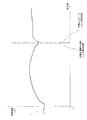
さて、 図5に示すのは、モデル的に示した図4と異なり、実際の流速を算出した状態を示したものである。
現在は、トランスジューサ20の端面からくさび内通過時間、配管内通過時間、および非測定流体内通過時間を、それぞれの幾何学形状および音速を用いて、内壁面の位置を算出している。
この図から明らかなように、流体配管の内壁に近い測定点は流速の変化が大きいため、内壁の位置の特定を誤ると、最終的な流量の算出に大きな誤差が生じてしまう。
流体配管の内壁の位置(=トランスジューサーからの距離を正確に算出すること)の計算を困難にしている要因は、トランスジューサの個体差、超音波受信回路の個体差(使われているコンデンサー等による遅延の個体差)が想定される。しかし、ばらつきの存在理由を解明したり、ばらつきの原因を除去することによって解消しようとすることは現実的ではない。Now, FIG. 5 shows a state where the actual flow velocity is calculated, unlike FIG. 4 shown as a model.
At present, the position of the inner wall surface is calculated from the end face of the transducer 20 using the respective geometric shapes and sound speeds of the passage time in the wedge, the passage time in the pipe, and the passage time in the non-measurement fluid.
As is clear from this figure, since the measurement point close to the inner wall of the fluid pipe has a large change in flow velocity, if the position of the inner wall is incorrectly specified, a large error occurs in the final flow rate calculation.
Factors that make it difficult to calculate the position of the inner wall of the fluid pipe (= accurately calculate the distance from the transducer) are due to individual differences in the transducer and individual differences in the ultrasonic reception circuit (such as the capacitors used) Individual differences in delay) are assumed. However, it is not practical to try to solve the problem by elucidating the reason for the existence of the variation or removing the cause of the variation.
本発明が解決しようとする課題は、超音波流量計において、流速分布の算出結果から内壁位置を特定する際の特定誤差を低減することによって、より正確な流量を計測する技術を提供することである。
請求項1から請求項3に記載の発明の目的は、超音波流量計において、流速分布の算出結果から内壁位置を特定する際の特定誤差を低減することによって、より正確な流量を計測する超音波流量計を提供することにある。
請求項4から請求項5に記載の発明の目的は、超音波流量計において、流速分布の算出結果から内壁位置を特定する際の特定誤差を低減することによって、より正確な流量を計測する流量計測方法を提供することにある。
請求項6から請求項7に記載の発明の目的は、超音波流量計において、流速分布の算出結果から内壁位置を特定する際の特定誤差を低減することによって、より正確な流量を計測する超音波流量計に実行させることとしたコンピュータプログラムを提供することにある。The problem to be solved by the present invention is to provide a technique for measuring a more accurate flow rate in an ultrasonic flowmeter by reducing a specific error when specifying an inner wall position from a calculation result of a flow velocity distribution. is there.
The object of the invention described in
An object of the invention according to
The object of the invention described in claim 6 to claim 7 is an ultrasonic flowmeter that is capable of measuring a more accurate flow rate by reducing a specific error when specifying an inner wall position from a flow velocity distribution calculation result. It is to provide a computer program to be executed by a sonic flow meter.
(請求項1)
請求項1記載の発明は、 所要周波数の超音波パルスを超音波トランスジューサから測定線に沿って流体配管内の被測定流体中へ入射させる超音波送信手段と、 被測定流体に入射された超音波パルスのうち測定領域から反射された超音波エコーを受信し、測定領域における被測定流体の流速分布を測定する流体速度分布測定手段と、 前記被測定流体の流速分布に基づいて、前記測定領域における被測定流体の流量を演算する流量演算手段とを備えて被測定流体の流量を測定する超音波流量計に係る。
前記の流体速度分布測定手段は、前記測定線に係る流体配管の内径方向位置と、その内径方向に対応する流体速度と二軸として流速分布を表す流速分布グラフを出力させるグラフ出力手段と、 そのグラフ出力手段にて出力された流速分布グラフから、変曲点を算出することによって内径方向の軸に対して内壁の位置を算出する内壁位置算出手段と備える。
その内壁位置算出手段は、前記の流速分布を補間して形成した二次曲線を微分して得たゼロ点に基づいて内壁位置を特定することとし、 前記の流量演算手段は、前記内壁位置算出手段が算出した内壁の位置に基づく積分演算に基づいて被測定流体の流量を測定することとした。
(Claim 1)
According to the first aspect of the present invention, there is provided an ultrasonic transmission means for causing an ultrasonic pulse having a required frequency to enter a fluid to be measured in a fluid pipe along a measurement line from the ultrasonic transducer, and an ultrasonic wave incident on the fluid to be measured. A fluid velocity distribution measuring means for receiving an ultrasonic echo reflected from the measurement region of the pulse and measuring a flow velocity distribution of the fluid under measurement in the measurement region; and based on the flow velocity distribution of the fluid under measurement in the measurement region The present invention relates to an ultrasonic flowmeter that includes a flow rate calculation unit that calculates a flow rate of a fluid to be measured and that measures the flow rate of the fluid to be measured.
The fluid velocity distribution measuring means includes a graph output means for outputting a flow velocity distribution graph representing a flow velocity distribution as a biaxial axis and a fluid velocity corresponding to the inner diameter direction of the fluid pipe according to the measurement line; Inner wall position calculating means for calculating the position of the inner wall with respect to the axis in the inner diameter direction by calculating an inflection point from the flow velocity distribution graph output by the graph output means.
The inner wall position calculating means specifies the inner wall position based on a zero point obtained by differentiating a quadratic curve formed by interpolating the flow velocity distribution, and the flow rate calculating means calculates the inner wall position. The flow rate of the fluid to be measured was measured based on the integral calculation based on the position of the inner wall calculated by the means.
(用語説明)
上記の超音波流量計には、一般のドップラ式超音波流量計と、相関法を用いた超音波流量計とを含む。相関法を用いた超音波流量計とは、例えば、特開2003−344131号に開示されているような超音波流量計である。
両者とも、所要周波数の超音波パルスを超音波トランスジューサから測定線に沿って流体配管内の被測定流体中へ入射させる超音波送信手段と、 被測定流体に入射された超音波パルスのうち測定領域から反射された超音波エコーを受信し、測定領域における被測定流体の流速分布を測定する流体速度分布測定手段と、 前記被測定流体の流速分布に基づいて、前記測定領域における被測定流体の流量を演算する流量演算手段とを備えて被測定流体の流量を測定する。(Glossary)
The ultrasonic flow meter includes a general Doppler ultrasonic flow meter and an ultrasonic flow meter using a correlation method. The ultrasonic flow meter using the correlation method is, for example, an ultrasonic flow meter as disclosed in JP-A-2003-344131.
In both cases, an ultrasonic transmission means for injecting an ultrasonic pulse of a required frequency from an ultrasonic transducer along a measurement line into a fluid to be measured in a fluid pipe, and a measurement region of the ultrasonic pulses incident on the fluid to be measured A fluid velocity distribution measuring means for receiving the ultrasonic echo reflected from the measurement region and measuring a flow velocity distribution of the fluid under measurement in the measurement region; The flow rate of the fluid to be measured is measured.
「流量演算手段」は、流量をm(t)とするとき、

また、上記の式(1)から、流体配管を流れる時間tの流量m(t)は、次式に書き換えることができる。
なお、配管内を流れる被測定流体の流れが、管軸方向の流れで半径方向や角度θの流れvr,vθを無視できるとすると、vx>>vr=vθとなり、流量計測は簡素化され、次式で表わされる。
「内壁位置算出手段」による「変曲点の算出」は、様々な数学的手法を用いればよい。例えば、流速分布を補間などの手法によって二次曲線としてそれを微分し、ゼロとなる点をもとにして算出する方法である。 Various mathematical methods may be used for “calculation of the inflection point” by the “inner wall position calculation means”. For example, a flow velocity distribution is differentiated as a quadratic curve by a technique such as interpolation, and is calculated based on a point that becomes zero.
(作用)
流体速度分布測定手段においては、測定線に係る流体配管の内径方向と、その内径方向に対応する流体速度と二軸として流速分布を表す流速分布グラフをグラフ出力手段が出力させる。そのグラフ出力手段にて出力された流速分布グラフから、内壁位置算出手段が変曲点を算出することによって内径方向の軸に対して内壁の位置を算出する。内壁位置算出手段が算出した内壁の位置に基づいて流量演算手段が積分演算をし、被測定流体の流量を算出することとなる。
内壁位置を正確に特定することにより、最終的な流量の算出誤差を低減させることができる。(Function)
In the fluid velocity distribution measuring means, the graph output means outputs a flow velocity distribution graph representing the flow velocity distribution as two axes with the inner diameter direction of the fluid piping related to the measurement line, the fluid velocity corresponding to the inner diameter direction. From the flow velocity distribution graph output by the graph output means, the inner wall position calculating means calculates the inflection point, thereby calculating the position of the inner wall with respect to the axis in the inner diameter direction. Based on the position of the inner wall calculated by the inner wall position calculating means, the flow rate calculating means performs an integral operation to calculate the flow rate of the fluid to be measured.
By accurately specifying the inner wall position, it is possible to reduce the final flow rate calculation error.
(請求項2)
請求項2記載の発明は、請求項1記載の超音波流量計を限定したものである。
すなわち、前記の流体速度分布測定手段には、内壁位置算出手段が算出した内壁の位置を手動入力によって微調整することが可能な微調整入力データ受信手段を備えたことを特徴とする。
内壁位置算出手段による自動算出の結果に対して、経験的な補正をする手段として「微調整入力データ受信手段」を備えたものである。例えば、内壁位置算出手段が算出した内壁の位置を縦軸として画面出力し、その縦軸をカーソルキーにて左右に移動させたり、移動後にリターンキーによって確定させたりする機能を併せ持つこととするのである。(Claim 2)
The invention according to
That is, the fluid velocity distribution measuring means includes a fine adjustment input data receiving means capable of finely adjusting the position of the inner wall calculated by the inner wall position calculating means by manual input.
“Fine adjustment input data receiving means” is provided as means for empirically correcting the result of automatic calculation by the inner wall position calculating means. For example, the position of the inner wall calculated by the inner wall position calculating means is output on the screen as a vertical axis, and the vertical axis is moved to the left and right with the cursor key, and has the function of confirming with the return key after the movement. is there.
(作用)
内壁位置算出手段による自動算出の結果に対して、経験的な判断から更なる補正をすることができるようにした。このにより、経験を踏まえた正確な内壁位置の特定が可能となり、最終的な流量の算出誤差を低減させることに寄与する。(Function)
The result of automatic calculation by the inner wall position calculating means can be further corrected from empirical judgment. This makes it possible to accurately identify the inner wall position based on experience, and contributes to reducing the final flow rate calculation error.
(請求項3)
請求項3に記載の発明は、所要周波数の超音波パルスを超音波トランスジューサから測定線に沿って流体配管内の被測定流体中へ入射させる超音波送信手段と、 被測定流体に入射された超音波パルスのうち測定領域から反射された超音波エコーを受信し、測定領域における被測定流体の流速分布を測定する流体速度分布測定手段と、 前記被測定流体の流速分布に基づいて、前記測定領域における被測定流体の流量を演算する流量演算手段とを備えて被測定流体の流量を測定する超音波流量計に係る。
前記の流体速度分布測定手段は、前記測定線に係る流体配管の内径方向位置と、その内径方向に対応する流体速度と二軸として流速分布を表す流速分布グラフを出力させるグラフ出力手段と、 内径方向の軸に対して内壁の位置に関する手動入力データを受け付ける手動入力データ受信手段と、 その手動入力データ受信手段が受け付けた手動入力データに基づいて内径方向の軸に対して内壁の位置を算出する内壁位置算出手段と備え、 その内壁位置算出手段は、前記の手動入力データを補間して形成した二次曲線を微分して得たゼロ点に基づいて内壁位置を特定することとし、 前記の流量演算手段は、前記内壁位置算出手段が算出した内壁の位置に基づく積分演算に基づいて被測定流体の流量を測定することとした。
(Claim 3)
According to a third aspect of the present invention, there is provided an ultrasonic transmission means for injecting an ultrasonic pulse having a required frequency from an ultrasonic transducer along a measurement line into a measured fluid in a fluid pipe, and an ultrasonic wave incident on the measured fluid. A fluid velocity distribution measuring means for receiving an ultrasonic echo reflected from the measurement region of the sound wave pulse and measuring a flow velocity distribution of the fluid under measurement in the measurement region; and the measurement region based on the flow velocity distribution of the fluid under measurement. And an ultrasonic flowmeter for measuring the flow rate of the fluid to be measured.
The fluid velocity distribution measuring means includes a graph output means for outputting a flow velocity distribution graph representing a flow velocity distribution as two axes, a fluid velocity corresponding to the inner diameter direction of the fluid pipe in accordance with the measurement line, and an inner diameter. Manual input data receiving means for receiving manual input data relating to the position of the inner wall with respect to the direction axis, and the position of the inner wall with respect to the inner diameter direction axis based on the manual input data received by the manual input data receiving means An inner wall position calculating means, the inner wall position calculating means specifies the inner wall position based on a zero point obtained by differentiating a quadratic curve formed by interpolating the manual input data, and the flow rate The calculating means measures the flow rate of the fluid to be measured based on the integral calculation based on the position of the inner wall calculated by the inner wall position calculating means.
以下のような発明を提供することもできる。
すなわち、所要周波数の超音波パルスを超音波トランスジューサから測定線に沿って流体配管内の被測定流体中へ入射させる超音波送信手段と、 被測定流体に入射された超音波パルスのうち測定領域から反射された超音波エコーを受信し、測定領域における被測定流体の流速分布を測定する流体速度分布測定手段と、 前記被測定流体の流速分布に基づいて、前記測定領域における被測定流体の流量を演算する流量演算手段とを備えて被測定流体の流量を測定する超音波流量計を用いた流量計測方法に係る。
すなわち、前記の流体速度分布測定手段によって、前記測定線に係る流体配管の内径方向位置と、その内径方向に対応する流体速度と二軸として流速分布を表す流速分布グラフを出力させるグラフ出力手順と、 内径方向の軸に対して内壁の位置を算出する内壁位置算出手順と、 前記の流量演算手段によって、前記内壁位置算出手順にて算出した内壁の位置に基づく積分演算に基づいて被測定流体の流量を演算する流量演算手順とを実行する流量計測方法である。
The following inventions can also be provided.
That is, an ultrasonic transmission means for causing an ultrasonic pulse of a required frequency to be incident from the ultrasonic transducer along the measurement line into the fluid to be measured in the fluid piping, and from the measurement region among the ultrasonic pulses incident on the fluid to be measured. Fluid velocity distribution measuring means for receiving the reflected ultrasonic echo and measuring the flow velocity distribution of the fluid under measurement in the measurement region; and based on the flow velocity distribution of the fluid under measurement, the flow rate of the fluid under measurement in the measurement region The present invention relates to a flow rate measurement method using an ultrasonic flowmeter that includes a flow rate calculation means for calculating a flow rate of a fluid to be measured.
That is, a graph output procedure for causing the fluid velocity distribution measuring means to output a flow velocity distribution graph representing a flow velocity distribution as two axes with a fluid velocity corresponding to the inner diameter direction of the fluid pipe in accordance with the measurement line; An inner wall position calculation procedure for calculating the position of the inner wall with respect to the axis in the inner diameter direction, and an integral calculation based on the position of the inner wall calculated in the inner wall position calculation procedure by the flow rate calculation means. This is a flow rate measurement method for executing a flow rate calculation procedure for calculating a flow rate.
以下のような発明を提供することもできる。
すなわち、所要周波数の超音波パルスを超音波トランスジューサから測定線に沿って流体配管内の被測定流体中へ入射させる超音波送信手段と、 被測定流体に入射された超音波パルスのうち測定領域から反射された超音波エコーを受信し、測定領域における被測定流体の流速分布を測定する流体速度分布測定手段と、 前記被測定流体の流速分布に基づいて、前記測定領域における被測定流体の流量を演算する流量演算手段とを備えて被測定流体の流量を測定する超音波流量計を用いた流量計測方法に係る。
前記の流体速度分布測定手段によって、前記測定線に係る流体配管の内径方向位置と、その内径方向に対応する流体速度と二軸として流速分布を表す流速分布グラフを出力させるグラフ出力手順と、 内径方向の軸に対して内壁の位置に関する手動入力データを受け付ける手動入力データ受信手順と、 その手動入力データ受信手順にて受け付けた手動入力データに基づいて内径方向の軸に対して内壁の位置を算出する内壁位置算出手順と、 前記の流量演算手段によって、前記内壁位置算出手順にて算出した内壁の位置に基づく積分演算に基づいて被測定流体の流量を演算する流量演算手順とを実行する流量計測方法である。
The following inventions can also be provided.
That is, an ultrasonic transmission means for causing an ultrasonic pulse of a required frequency to be incident from the ultrasonic transducer along the measurement line into the fluid to be measured in the fluid piping, and from the measurement region among the ultrasonic pulses incident on the fluid to be measured. Fluid velocity distribution measuring means for receiving the reflected ultrasonic echo and measuring the flow velocity distribution of the fluid under measurement in the measurement region; and based on the flow velocity distribution of the fluid under measurement, the flow rate of the fluid under measurement in the measurement region The present invention relates to a flow rate measurement method using an ultrasonic flowmeter that includes a flow rate calculation means for calculating a flow rate of a fluid to be measured.
A graph output procedure for causing the fluid velocity distribution measuring means to output a flow velocity distribution graph representing the flow velocity distribution as two axes with a fluid velocity corresponding to the inner diameter direction of the fluid pipe in accordance with the measurement line; Manual input data reception procedure for receiving manual input data related to the position of the inner wall with respect to the direction axis, and calculation of the position of the inner wall with respect to the inner diameter direction axis based on the manual input data received in the manual input data reception procedure A flow rate measurement procedure for performing a flow rate calculation procedure for calculating a flow rate of the fluid to be measured based on an integral calculation based on the position of the inner wall calculated in the inner wall position calculation procedure by the flow rate calculation means. Is the method.
(請求項4)
請求項4に記載の発明は、 所要周波数の超音波パルスを超音波トランスジューサから測定線に沿って流体配管内の被測定流体中へ入射させる超音波送信手段と、 被測定流体に入射された超音波パルスのうち測定領域から反射された超音波エコーを受信し、測定領域における被測定流体の流速分布を測定する流体速度分布測定手段と、 前記被測定流体の流速分布に基づいて、前記測定領域における被測定流体の流量を演算する流量演算手段とを備えて被測定流体の流量を測定する超音波流量計を制御するプログラムに係る。
そのプログラムは、前記測定線に係る流体配管の内径方向位置と、その内径方向に対応する流体速度と二軸として流速分布を表す流速分布グラフを前記の流体速度分布測定手段に出力させるグラフ出力手順と、 そのグラフ出力手順にて出力された流速分布グラフから二次曲線を特定して微分し、セロ点から変曲点を算出することによって内径方向の軸に対して内壁の位置を算出する内壁位置算出手順と、 前記の内壁位置算出手順にて算出した内壁の位置に基づく積分演算に基づいて被測定流体の流量を演算する流量演算手順と、を超音波流量計に実行させることとしたコンピュータプログラムである。
(Claim 4)
The invention according to
The program outputs a flow velocity distribution graph representing a flow velocity distribution as a biaxial position and a fluid velocity corresponding to the inner diameter direction of the fluid pipe related to the measurement line to the fluid velocity distribution measuring means. The inner wall calculates the position of the inner wall with respect to the axis in the inner diameter direction by identifying and differentiating the quadratic curve from the flow velocity distribution graph output in the graph output procedure and calculating the inflection point from the cell point A computer that causes an ultrasonic flowmeter to execute a position calculation procedure and a flow rate calculation procedure for calculating a flow rate of a fluid to be measured based on an integral calculation based on the position of the inner wall calculated in the inner wall position calculation procedure. It is a program.
以下のような発明を提供することもできる。
すなわち、所要周波数の超音波パルスを超音波トランスジューサから測定線に沿って流体配管内の被測定流体中へ入射させる超音波送信手段と、 被測定流体に入射された超音波パルスのうち測定領域から反射された超音波エコーを受信し、測定領域における被測定流体の流速分布を測定する流体速度分布測定手段と、 前記被測定流体の流速分布に基づいて、前記測定領域における被測定流体の流量を演算する流量演算手段とを備えて被測定流体の流量を測定する超音波流量計を制御するプログラムに係る。
そのプログラムは、前記測定線に係る流体配管の内径方向位置と、その内径方向に対応する流体速度と二軸として流速分布を表す流速分布グラフを前記の流体速度分布測定手段に出力させるグラフ出力手順と、 内径方向の軸に対して内壁の位置に関する手動入力データを受け付ける手動入力データ受信手順と、 内壁の位置を算出する内壁位置算出手順と、 前記の内壁位置算出手順にて算出した内壁の位置に基づく積分演算に基づいて被測定流体の流量を演算する流量演算手順とを超音波流量計に実行させることとしたコンピュータプログラムである。
The following inventions can also be provided.
That is, an ultrasonic transmission means for causing an ultrasonic pulse of a required frequency to be incident from the ultrasonic transducer along the measurement line into the fluid to be measured in the fluid piping, and from the measurement region among the ultrasonic pulses incident on the fluid to be measured. Fluid velocity distribution measuring means for receiving the reflected ultrasonic echo and measuring the flow velocity distribution of the fluid under measurement in the measurement region; and based on the flow velocity distribution of the fluid under measurement, the flow rate of the fluid under measurement in the measurement region The present invention relates to a program for controlling an ultrasonic flowmeter that includes a flow rate calculation means for calculating a flow rate of a fluid to be measured.
The program outputs a flow velocity distribution graph representing a flow velocity distribution as a biaxial position and a fluid velocity corresponding to the inner diameter direction of the fluid pipe related to the measurement line to the fluid velocity distribution measuring means. A manual input data receiving procedure for receiving manual input data relating to the position of the inner wall with respect to the inner diameter direction axis; an inner wall position calculating procedure for calculating the inner wall position; and an inner wall position calculated by the inner wall position calculating procedure. And a flow rate calculation procedure for calculating the flow rate of the fluid to be measured based on the integral calculation based on the above.
請求項4または上記に係るコンピュータプログラムを、記録媒体へ記憶させて提供することもできる。ここで、「記録媒体」とは、それ自身では空間を占有し得ないプログラムを担持することができる媒体であり、例えば、フレキシブルディスク、ハードディスク、CD−R、MO(光磁気ディスク)、DVD−Rなどである。
また、これらの発明に係るプログラムを格納したコンピュータから、通信回線を通じて他のコンピュータへ伝送することも可能である。
なお、汎用的なコンピュータを備えた超音波流量計に対して、上記のような各手段を達成可能であるようなプログラムをプリインストール、あるいはダウンロードすることで、請求項1等に係る機能を備えた超音波流量計を形成することも可能である。
The computer program according to
It is also possible to transmit from a computer storing a program according to these inventions to another computer through a communication line.
The function according to
請求項1から請求項3に記載の発明によれば、超音波流量計において、流速分布の算出結果から内壁位置を特定する際の特定誤差を低減することによって、より正確な流量を計測する超音波流量計を提供することができた。
請求項4から請求項5に記載の発明によれば、超音波流量計において、流速分布の算出結果から内壁位置を特定する際の特定誤差を低減することによって、より正確な流量を計測する流量計測方法を提供することができた。
請求項6から請求項7に記載の発明によれば、超音波流量計において、流速分布の算出結果から内壁位置を特定する際の特定誤差を低減することによって、より正確な流量を計測する超音波流量計に実行させることとしたコンピュータプログラムを提供することができた。According to the first to third aspects of the present invention, in the ultrasonic flowmeter, an ultrasonic flowmeter that measures a more accurate flow rate by reducing a specific error when specifying the inner wall position from the calculation result of the flow velocity distribution. A sonic flow meter could be provided.
According to the invention of
According to the invention described in claims 6 to 7, in the ultrasonic flowmeter, the ultrasonic flowmeter can measure the flow rate more accurately by reducing the specific error when specifying the inner wall position from the calculation result of the flow velocity distribution. It was possible to provide a computer program to be executed by the sonic flow meter.
以下、本発明を実施の形態及び図面に基づいて、更に詳しく説明する。ここで使用する図面は、図1から図3および図5である。図1および図2は、実施形態を概念的に説明したものである。図3は、図5にて出力された流速分布を抽出するとともに、図1の実施形態の主要部分を示したものである。
(図1)
図1は、被測定流体が流れる流体配管の流量を計測するための超音波流量計において、被測定流体に入射された超音波パルスの測定領域から反射された超音波エコーを受信する受信機を兼ねた超音波送受信手段(トランスジューサ)を備える。Hereinafter, the present invention will be described in more detail based on embodiments and drawings. The drawings used here are FIGS. 1 to 3 and FIG. 5. 1 and 2 conceptually describe the embodiment. FIG. 3 shows the main part of the embodiment of FIG. 1 while extracting the flow velocity distribution output in FIG.
(Figure 1)
FIG. 1 shows an ultrasonic flowmeter for measuring a flow rate of a fluid pipe through which a fluid to be measured flows, and a receiver that receives an ultrasonic echo reflected from a measurement region of an ultrasonic pulse incident on the fluid to be measured. Also equipped with ultrasonic transmission / reception means (transducer).
トランスジューサは、被測定流体に入射された超音波パルスの測定領域から反射された超音波エコーを受信し、測定領域における被測定流体の流速分布を測定する流体速度分布測定手段とを兼ねている。そして、その流速分布に基づいて被測定流体の流量を時間依存で求める流量演算手段としてのマイコン、CPU、MPU等のコンピュータと、このコンピュータからの出力を時系列的に表示可能な表示装置(図1中では「出力手段(モニタ)」として図示)とに接続されている。 The transducer receives ultrasonic echoes reflected from the measurement region of the ultrasonic pulse incident on the fluid to be measured, and also serves as fluid velocity distribution measuring means for measuring the flow velocity distribution of the fluid to be measured in the measurement region. Then, a computer such as a microcomputer, CPU, MPU, etc. as a flow rate calculation means for obtaining the flow rate of the fluid to be measured in a time-dependent manner based on the flow velocity distribution, and a display device (FIG. 1 is connected to “output means (monitor)”.
また、トランスジューサには、トランスジューサを加振させる信号発生器としての加振用アンプを備えており、加振用アンプから所要の基本周波数のパルス電気信号が超音波トランスジューサへ入力されるようになっている。そして、パルス電気信号の印加により基本周波数の超音波パルスが測定線に沿って発信せしめられる。超音波パルスは、パルス幅5mm程度で拡がりをほとんど持たない直進性のビームである。これは、図4にて説明したことと同様である。 In addition, the transducer is provided with a vibration amplifier as a signal generator for vibrating the transducer, and a pulse electric signal having a required fundamental frequency is input from the vibration amplifier to the ultrasonic transducer. Yes. Then, an ultrasonic pulse having a fundamental frequency is transmitted along the measurement line by applying the pulse electric signal. The ultrasonic pulse is a straight beam having a pulse width of about 5 mm and hardly spreading. This is the same as described in FIG.
トランスジューサは、発信された超音波パルスが流体配管内の被測定流体中の反射体(例えば気泡)に当って反射されて超音波エコーとなり、トランスジューサが兼ねたエコー受信手段にて受信され、その反射波レシーバーにてエコー電気信号へ変換される。このエコー電気信号は、増幅器で増幅された後、AD変換器を通ってデジタル化される。そして、デジタル化されたデジタルエコー信号が流速分布計測回路を備えた流速分布測定手段に入力される。 In the transducer, the transmitted ultrasonic pulse is reflected by a reflector (for example, a bubble) in the fluid to be measured in the fluid pipe to be reflected as an ultrasonic echo, which is received by the echo receiving means also serving as the transducer, and the reflection It is converted into an echo electrical signal by a wave receiver. The echo electric signal is amplified by an amplifier and then digitized through an AD converter. Then, the digitized digital echo signal is input to a flow velocity distribution measuring means having a flow velocity distribution measuring circuit.
流速分布測定手段では、発信用アンプからの基本周波数の電気信号がデジタル化されて入力され、両信号の周波数差からドップラシフトに基づく流速の変化もしくは両信号の相互相関値を用いて流速を計測し、測定線に沿う測定領域の流速分布を算出している。測定領域の流速分布を超音波の入射角度αで較正することによって、流体配管の横断面における流速分布を算出することができる。算出された流速分布は、モニタ上にグラフとして出力される。 In the flow velocity distribution measuring means, the electrical signal of the fundamental frequency from the amplifier for transmission is digitized and input, and the flow velocity is measured using the change in flow velocity based on the Doppler shift or the cross-correlation value of both signals from the frequency difference between both signals. The flow velocity distribution in the measurement area along the measurement line is calculated. By calibrating the flow velocity distribution in the measurement area with the incident angle α of the ultrasonic wave, the flow velocity distribution in the cross section of the fluid piping can be calculated. The calculated flow velocity distribution is output as a graph on the monitor.
グラフとして算出する際、「内壁位置算出手段」によって、仮の内壁位置をも出力する。その「仮の内壁位置」は、例えば、流速分布を補間などの手法によって二次曲線としてそれを微分し、ゼロとなる点をもとにして算出する。なお、「仮の内壁位置」の算出については、様々な数学的手法を組み合わせたり、場合分けして使い分けたりすることとしてもよい。 When calculating as a graph, the “inner wall position calculating means” also outputs the temporary inner wall position. The “temporary inner wall position” is calculated based on a point where the flow velocity distribution is differentiated as a quadratic curve by a technique such as interpolation and becomes zero. In addition, regarding the calculation of the “temporary inner wall position”, various mathematical methods may be combined, or may be used in different cases.
モニタ上のグラフを目視確認した測定者は、手動入力データ受信手段(例えば、当該モニタに接続されたキーボードのカーソルキー)を用いて、内壁位置についての補正データを入力する。具体的には、図3に示すように、カーソルキーなどを使って、内壁位置を示すラインを左右に移動させるのである。
もちろん、補正の必要がないと測定者が判断すれば、補正データの入力は行わなくてよい。ただし、補正データの入力は不要である旨を内壁位置算出手段へ入力する必要がある。The measurer who visually confirms the graph on the monitor inputs correction data for the inner wall position using manual input data receiving means (for example, a cursor key of a keyboard connected to the monitor). Specifically, as shown in FIG. 3, a line indicating the inner wall position is moved left and right using a cursor key or the like.
Of course, if the measurer determines that no correction is required, the correction data need not be input. However, it is necessary to input to the inner wall position calculating means that correction data is not required to be input.
決定された内壁位置データを用いて、流量演算手段が被測定流体の流量を算出する。そしてその算出流量を、再びモニタ上に出力させる。
本実施形態に係る超音波流量計は、測定領域の流速分布を時間依存で求めることができるので、被測定流体の流量を定常状態、非定常状態如何を問わず、正確に精度よく求めることができる。また、内壁位置算出手段によって、仮の内壁位置を自動算出し、更に、測定者の経験などをふまえた補正を加味することができるので、内壁位置の算出に伴う測定誤差の抑制に寄与する。The flow rate calculation means calculates the flow rate of the fluid to be measured using the determined inner wall position data. The calculated flow rate is output again on the monitor.
Since the ultrasonic flowmeter according to the present embodiment can obtain the flow velocity distribution in the measurement region in a time-dependent manner, the flow rate of the fluid to be measured can be obtained accurately and accurately regardless of whether it is in a steady state or an unsteady state. it can. Further, the temporary inner wall position can be automatically calculated by the inner wall position calculating means, and further corrections based on the experience of the measurer can be taken into account, thereby contributing to the suppression of measurement errors accompanying the calculation of the inner wall position.
(図2)
図2に示す実施形態は、図1にて用いていた「内壁位置算出手段」における自動算出を省略し、測定者によるデータ入力によって内壁位置を決定するものである。何らかの事情によって測定点が少なくなってしまい、流速分布を補間などの手法によって連続曲線とできないような場合にも対応できる。ただし、本実施形態の場合には、測定者らによる内壁位置のデータ入力が必須であり、これがないと、最終的な流量算出が行えない。
なお、自動算出を省略することによって装置全体の簡素化、コストダウンに寄与するというメリットがある。(Figure 2)
In the embodiment shown in FIG. 2, the automatic calculation in the “inner wall position calculation means” used in FIG. 1 is omitted, and the inner wall position is determined by data input by the measurer. It is possible to cope with a case where the number of measurement points decreases due to some circumstances and the flow velocity distribution cannot be made a continuous curve by a technique such as interpolation. However, in the case of this embodiment, the data input of the inner wall position by the measurers is indispensable, and without this, the final flow rate cannot be calculated.
In addition, there is a merit that it contributes to simplification of the whole apparatus and cost reduction by omitting automatic calculation.
上述してきた実施形態では、図3を中心に、内壁位置についての右側(測定線上では遠い点)について説明してきたが、ゼロ点についても自動算出したり、測定者らによる補正が行えるようにしている。 In the embodiment described above, the right side of the inner wall position (a far point on the measurement line) has been described with reference to FIG. 3, but the zero point can also be automatically calculated or corrected by the measurers. Yes.
本願発明は、ドップラ式超音波流量計に限られず、一般の超音波流量計に属する流量計においても採用することができる。
また、超音波流量計の製造業のほか、超音波流量計取り付け業、メンテナンス業においても用いられる。The present invention is not limited to the Doppler type ultrasonic flowmeter, but can also be adopted in a flowmeter belonging to a general ultrasonic flowmeter.
In addition to the manufacturing industry of ultrasonic flowmeters, it is also used in the installation and maintenance industries of ultrasonic flowmeters.
Claims (4)
前記の流体速度分布測定手段は、前記測定線に係る流体配管の内径方向位置と、その内径方向に対応する流体速度と二軸として流速分布を表す流速分布グラフを出力させるグラフ出力手段と、
そのグラフ出力手段にて出力された流速分布グラフから、変曲点を算出することによって内径方向の軸に対して内壁の位置を算出する内壁位置算出手段と備え、
その内壁位置算出手段は、前記の流速分布を補間して形成した二次曲線を微分して得たゼロ点に基づいて内壁位置を特定することとし、
前記の流量演算手段は、前記内壁位置算出手段が算出した内壁の位置に基づく積分演算に基づいて被測定流体の流量を測定することとした超音波流量計。Ultrasonic transmission means for injecting ultrasonic pulses of the required frequency from the ultrasonic transducer along the measurement line into the fluid to be measured in the fluid piping, and reflected from the measurement area among the ultrasonic pulses incident on the fluid to be measured. A fluid velocity distribution measuring means for receiving the measured ultrasonic echo and measuring the flow velocity distribution of the fluid under measurement in the measurement region; and calculating the flow rate of the fluid under measurement in the measurement region based on the flow velocity distribution of the fluid under measurement. An ultrasonic flowmeter comprising a flow rate calculation means for measuring the flow rate of a fluid to be measured,
The fluid velocity distribution measuring means includes a graph output means for outputting a flow velocity distribution graph representing a flow velocity distribution as a biaxial axis and a fluid velocity corresponding to the inner diameter direction of the fluid pipe according to the measurement line;
An inner wall position calculating means for calculating the position of the inner wall with respect to the axis in the inner diameter direction by calculating an inflection point from the flow velocity distribution graph output by the graph output means;
The inner wall position calculating means specifies the inner wall position based on a zero point obtained by differentiating a quadratic curve formed by interpolating the flow velocity distribution,
The ultrasonic flowmeter, wherein the flow rate calculation means measures the flow rate of the fluid to be measured based on an integral calculation based on the position of the inner wall calculated by the inner wall position calculation means.
前記の流体速度分布測定手段は、前記測定線に係る流体配管の内径方向位置と、その内径方向に対応する流体速度と二軸として流速分布を表す流速分布グラフを出力させるグラフ出力手段と、
内径方向の軸に対して内壁の位置に関する手動入力データを受け付ける手動入力データ受信手段と、
その手動入力データ受信手段が受け付けた手動入力データに基づいて内径方向の軸に対して内壁の位置を算出する内壁位置算出手段と備え、
その内壁位置算出手段は、前記の手動入力データを補間して形成した二次曲線を微分して得たゼロ点に基づいて内壁位置を特定することとし、
前記の流量演算手段は、前記内壁位置算出手段が算出した内壁の位置に基づく積分演算に基づいて被測定流体の流量を測定することとした超音波流量計。Ultrasonic transmission means for injecting ultrasonic pulses of the required frequency from the ultrasonic transducer along the measurement line into the fluid to be measured in the fluid piping, and reflected from the measurement area among the ultrasonic pulses incident on the fluid to be measured. A fluid velocity distribution measuring means for receiving the measured ultrasonic echo and measuring the flow velocity distribution of the fluid under measurement in the measurement region; and calculating the flow rate of the fluid under measurement in the measurement region based on the flow velocity distribution of the fluid under measurement. An ultrasonic flowmeter comprising a flow rate calculation means for measuring the flow rate of a fluid to be measured,
The fluid velocity distribution measuring means includes a graph output means for outputting a flow velocity distribution graph representing a flow velocity distribution as a biaxial axis and a fluid velocity corresponding to the inner diameter direction of the fluid pipe according to the measurement line;
Manual input data receiving means for receiving manual input data relating to the position of the inner wall with respect to the axis in the inner diameter direction;
Inner wall position calculating means for calculating the position of the inner wall with respect to the axis in the inner diameter direction based on the manual input data received by the manual input data receiving means,
The inner wall position calculating means specifies the inner wall position based on a zero point obtained by differentiating a quadratic curve formed by interpolating the manual input data,
The ultrasonic flowmeter, wherein the flow rate calculation means measures the flow rate of the fluid to be measured based on an integral calculation based on the position of the inner wall calculated by the inner wall position calculation means.
そのプログラムは、前記測定線に係る流体配管の内径方向位置と、その内径方向に対応する流体速度と二軸として流速分布を表す流速分布グラフを前記の流体速度分布測定手段に出力させるグラフ出力手順と、
そのグラフ出力手順にて出力された流速分布グラフから二次曲線を特定して微分し、セロ点から変曲点を算出することによって内径方向の軸に対して内壁の位置を算出する内壁位置算出手順と、
前記の内壁位置算出手順にて算出した内壁の位置に基づく積分演算に基づいて被測定流体の流量を演算する流量演算手順と、を超音波流量計に実行させることとしたコンピュータプログラム。Ultrasonic transmission means for injecting ultrasonic pulses of the required frequency from the ultrasonic transducer along the measurement line into the fluid to be measured in the fluid piping, and reflected from the measurement area among the ultrasonic pulses incident on the fluid to be measured. A fluid velocity distribution measuring means for receiving the measured ultrasonic echo and measuring the flow velocity distribution of the fluid under measurement in the measurement region; and calculating the flow rate of the fluid under measurement in the measurement region based on the flow velocity distribution of the fluid under measurement. A program for controlling an ultrasonic flowmeter comprising a flow rate calculation means for measuring a flow rate of a fluid to be measured,
The program outputs a flow velocity distribution graph representing a flow velocity distribution as a biaxial position and a fluid velocity corresponding to the inner diameter direction of the fluid pipe related to the measurement line to the fluid velocity distribution measuring means. When,
Inner wall position calculation to calculate the inner wall position with respect to the axis in the inner diameter direction by identifying and differentiating a quadratic curve from the flow velocity distribution graph output in the graph output procedure and calculating the inflection point from the cell point Procedure and
A computer program that causes an ultrasonic flow meter to execute a flow rate calculation procedure for calculating a flow rate of a fluid to be measured based on an integral calculation based on the position of the inner wall calculated in the inner wall position calculation procedure.
Priority Applications (1)
| Application Number | Priority Date | Filing Date | Title |
|---|---|---|---|
| JP2005516672A JP4827006B2 (en) | 2003-12-26 | 2004-12-24 | Ultrasonic flow meter, flow measurement method and computer program |
Applications Claiming Priority (4)
| Application Number | Priority Date | Filing Date | Title |
|---|---|---|---|
| JP2003435909 | 2003-12-26 | ||
| JP2003435909 | 2003-12-26 | ||
| JP2005516672A JP4827006B2 (en) | 2003-12-26 | 2004-12-24 | Ultrasonic flow meter, flow measurement method and computer program |
| PCT/JP2004/019432 WO2005064287A1 (en) | 2003-12-26 | 2004-12-24 | Ultrasonic flow meter, flow measurement method, and computer program |
Publications (2)
| Publication Number | Publication Date |
|---|---|
| JPWO2005064287A1 JPWO2005064287A1 (en) | 2007-07-19 |
| JP4827006B2 true JP4827006B2 (en) | 2011-11-30 |
Family
ID=34736650
Family Applications (1)
| Application Number | Title | Priority Date | Filing Date |
|---|---|---|---|
| JP2005516672A Expired - Fee Related JP4827006B2 (en) | 2003-12-26 | 2004-12-24 | Ultrasonic flow meter, flow measurement method and computer program |
Country Status (4)
| Country | Link |
|---|---|
| US (1) | US20070107535A1 (en) |
| EP (1) | EP1701139A1 (en) |
| JP (1) | JP4827006B2 (en) |
| WO (1) | WO2005064287A1 (en) |
Families Citing this family (3)
| Publication number | Priority date | Publication date | Assignee | Title |
|---|---|---|---|---|
| JP2005241546A (en) | 2004-02-27 | 2005-09-08 | Fuji Electric Systems Co Ltd | Doppler ultrasonic flowmeter, processing device thereof and program |
| US20100218618A1 (en) * | 2006-01-20 | 2010-09-02 | The Tokyo Electric Power Co., Inc. | Doppler type ultrasonic flow meter, flow metering method, and computer program |
| JP7160672B2 (en) * | 2018-12-28 | 2022-10-25 | 株式会社キーエンス | gas flow meter |
Citations (2)
| Publication number | Priority date | Publication date | Assignee | Title |
|---|---|---|---|---|
| JPS6219854B2 (en) * | 1978-09-22 | 1987-05-01 | Masanobu Hogaki | |
| JP2003130699A (en) * | 2001-10-26 | 2003-05-08 | Tokyo Electric Power Co Inc:The | Doppler-type ultrasonic flowmeter |
Family Cites Families (7)
| Publication number | Priority date | Publication date | Assignee | Title |
|---|---|---|---|---|
| US4397194A (en) * | 1981-04-07 | 1983-08-09 | Fischer & Porter Company | Ultrasonic flowmeter including means to measure pipe geometry |
| JPH10281832A (en) * | 1997-04-08 | 1998-10-23 | Hitachi Ltd | Pulse doppler type ultrasonic flowmeter |
| US6067861A (en) * | 1998-06-18 | 2000-05-30 | Battelle Memorial Institute | Method and apparatus for ultrasonic doppler velocimetry using speed of sound and reflection mode pulsed wideband doppler |
| JP2000097742A (en) * | 1998-09-25 | 2000-04-07 | Tokyo Electric Power Co Inc:The | Doppler-type ultrasonic flowmeter |
| US6158288A (en) * | 1999-01-28 | 2000-12-12 | Dolphin Technology, Inc. | Ultrasonic system for measuring flow rate, fluid velocity, and pipe diameter based upon time periods |
| US6470749B1 (en) * | 2001-05-08 | 2002-10-29 | Halliburton Energy Services, Inc. | Method and apparatus for pulsed ultrasonic doppler measurement of wall deposition |
| CA2488036C (en) * | 2002-06-04 | 2011-08-09 | The Tokyo Electric Power Company, Incorporated | Doppler type ultrasonic flowmeter, method of operation and flow rate measuring method |
-
2004
- 2004-12-24 JP JP2005516672A patent/JP4827006B2/en not_active Expired - Fee Related
- 2004-12-24 WO PCT/JP2004/019432 patent/WO2005064287A1/en active Application Filing
- 2004-12-24 EP EP04807788A patent/EP1701139A1/en not_active Withdrawn
- 2004-12-24 US US10/584,318 patent/US20070107535A1/en not_active Abandoned
Patent Citations (2)
| Publication number | Priority date | Publication date | Assignee | Title |
|---|---|---|---|---|
| JPS6219854B2 (en) * | 1978-09-22 | 1987-05-01 | Masanobu Hogaki | |
| JP2003130699A (en) * | 2001-10-26 | 2003-05-08 | Tokyo Electric Power Co Inc:The | Doppler-type ultrasonic flowmeter |
Also Published As
| Publication number | Publication date |
|---|---|
| EP1701139A1 (en) | 2006-09-13 |
| US20070107535A1 (en) | 2007-05-17 |
| WO2005064287A1 (en) | 2005-07-14 |
| JPWO2005064287A1 (en) | 2007-07-19 |
Similar Documents
| Publication | Publication Date | Title |
|---|---|---|
| JP4953001B2 (en) | Flow rate measuring device, flow rate measuring method, and computer program | |
| JP3795510B2 (en) | Ultrasonic flow velocity distribution meter and flow meter, ultrasonic flow velocity distribution and flow measurement method, ultrasonic flow velocity distribution and flow measurement processing program | |
| JP2006030041A (en) | Clamp-on type doppler type ultrasonic flow velocity distribution meter | |
| EP2202494B1 (en) | Ultrasonic meter | |
| JP2005241546A (en) | Doppler ultrasonic flowmeter, processing device thereof and program | |
| JP2004271496A (en) | Ultrasonic flow measuring method | |
| JP4535065B2 (en) | Doppler ultrasonic flow meter | |
| JP4827006B2 (en) | Ultrasonic flow meter, flow measurement method and computer program | |
| US20050154307A1 (en) | Apparatus and method for measuring a fluid velocity profile using acoustic doppler effect | |
| CN108431554B (en) | Fluid measuring device | |
| JP5012513B2 (en) | Doppler ultrasonic flow meter, flow measurement method and computer program | |
| JP5113343B2 (en) | Ultrasonic flow meter | |
| JPH0447770B2 (en) | ||
| KR101059931B1 (en) | Flow measurement method | |
| JP4827007B2 (en) | Ultrasonic flow meter | |
| RU2471153C2 (en) | Method and system for measurement of total flow of liquid medium and ultrasonic flow metre | |
| JP5483192B2 (en) | Ultrasonic flow meter | |
| JP7140266B2 (en) | Flow measurement device | |
| JPH11351928A (en) | Flowmetr and flow rate measuring method | |
| Mahadeva et al. | Studies of the accuracy of clamp-on transit time ultrasonic flowmeters | |
| KR101324574B1 (en) | Clamp-on type ultrasonic flowmeter and the measuring method of correction data | |
| JP2005195371A (en) | Ultrasonic flowmeter, and sound absorbing material for ultrasonic flowmeter | |
| JP2006194634A (en) | Doppler-type ultrasonic flowmeter, method for adjusting transmission voltage to ultrasonic vibrator in it, and method for monitoring state in fluid inside piping | |
| JP2005195372A (en) | Ultrasonic flowmeter, and wedge used for ultrasonic flowmeter | |
| JP2006126035A (en) | Doppler ultrasonic flowmeter, flow measurement method, and computer program |
Legal Events
| Date | Code | Title | Description |
|---|---|---|---|
| A621 | Written request for application examination |
Free format text: JAPANESE INTERMEDIATE CODE: A621 Effective date: 20071106 |
|
| A131 | Notification of reasons for refusal |
Free format text: JAPANESE INTERMEDIATE CODE: A131 Effective date: 20101124 |
|
| A521 | Written amendment |
Free format text: JAPANESE INTERMEDIATE CODE: A523 Effective date: 20110120 |
|
| TRDD | Decision of grant or rejection written | ||
| A01 | Written decision to grant a patent or to grant a registration (utility model) |
Free format text: JAPANESE INTERMEDIATE CODE: A01 Effective date: 20110822 |
|
| A01 | Written decision to grant a patent or to grant a registration (utility model) |
Free format text: JAPANESE INTERMEDIATE CODE: A01 |
|
| FPAY | Renewal fee payment (event date is renewal date of database) |
Free format text: PAYMENT UNTIL: 20140922 Year of fee payment: 3 |
|
| R150 | Certificate of patent or registration of utility model |
Free format text: JAPANESE INTERMEDIATE CODE: R150 |
|
| A61 | First payment of annual fees (during grant procedure) |
Free format text: JAPANESE INTERMEDIATE CODE: A61 Effective date: 20110904 |
|
| S533 | Written request for registration of change of name |
Free format text: JAPANESE INTERMEDIATE CODE: R313533 |
|
| R350 | Written notification of registration of transfer |
Free format text: JAPANESE INTERMEDIATE CODE: R350 |
|
| LAPS | Cancellation because of no payment of annual fees |