JP4826462B2 - Dispersion compensator, optical transmission system, and optical transmission method - Google Patents
Dispersion compensator, optical transmission system, and optical transmission method Download PDFInfo
- Publication number
- JP4826462B2 JP4826462B2 JP2006342070A JP2006342070A JP4826462B2 JP 4826462 B2 JP4826462 B2 JP 4826462B2 JP 2006342070 A JP2006342070 A JP 2006342070A JP 2006342070 A JP2006342070 A JP 2006342070A JP 4826462 B2 JP4826462 B2 JP 4826462B2
- Authority
- JP
- Japan
- Prior art keywords
- dispersion
- fiber
- wavelength
- compensation
- group
- Prior art date
- Legal status (The legal status is an assumption and is not a legal conclusion. Google has not performed a legal analysis and makes no representation as to the accuracy of the status listed.)
- Expired - Fee Related
Links
Images


Classifications
-
- H—ELECTRICITY
- H04—ELECTRIC COMMUNICATION TECHNIQUE
- H04B—TRANSMISSION
- H04B10/00—Transmission systems employing electromagnetic waves other than radio-waves, e.g. infrared, visible or ultraviolet light, or employing corpuscular radiation, e.g. quantum communication
- H04B10/25—Arrangements specific to fibre transmission
- H04B10/2507—Arrangements specific to fibre transmission for the reduction or elimination of distortion or dispersion
- H04B10/2513—Arrangements specific to fibre transmission for the reduction or elimination of distortion or dispersion due to chromatic dispersion
- H04B10/2525—Arrangements specific to fibre transmission for the reduction or elimination of distortion or dispersion due to chromatic dispersion using dispersion-compensating fibres
-
- G—PHYSICS
- G02—OPTICS
- G02B—OPTICAL ELEMENTS, SYSTEMS OR APPARATUS
- G02B6/00—Light guides; Structural details of arrangements comprising light guides and other optical elements, e.g. couplings
- G02B6/24—Coupling light guides
- G02B6/26—Optical coupling means
- G02B6/28—Optical coupling means having data bus means, i.e. plural waveguides interconnected and providing an inherently bidirectional system by mixing and splitting signals
- G02B6/293—Optical coupling means having data bus means, i.e. plural waveguides interconnected and providing an inherently bidirectional system by mixing and splitting signals with wavelength selective means
- G02B6/29379—Optical coupling means having data bus means, i.e. plural waveguides interconnected and providing an inherently bidirectional system by mixing and splitting signals with wavelength selective means characterised by the function or use of the complete device
- G02B6/29392—Controlling dispersion
- G02B6/29394—Compensating wavelength dispersion
-
- G—PHYSICS
- G02—OPTICS
- G02B—OPTICAL ELEMENTS, SYSTEMS OR APPARATUS
- G02B6/00—Light guides; Structural details of arrangements comprising light guides and other optical elements, e.g. couplings
- G02B6/24—Coupling light guides
- G02B6/26—Optical coupling means
- G02B6/28—Optical coupling means having data bus means, i.e. plural waveguides interconnected and providing an inherently bidirectional system by mixing and splitting signals
- G02B6/293—Optical coupling means having data bus means, i.e. plural waveguides interconnected and providing an inherently bidirectional system by mixing and splitting signals with wavelength selective means
- G02B6/29379—Optical coupling means having data bus means, i.e. plural waveguides interconnected and providing an inherently bidirectional system by mixing and splitting signals with wavelength selective means characterised by the function or use of the complete device
- G02B6/29395—Optical coupling means having data bus means, i.e. plural waveguides interconnected and providing an inherently bidirectional system by mixing and splitting signals with wavelength selective means characterised by the function or use of the complete device configurable, e.g. tunable or reconfigurable
Description
本発明は、分散補償器、及びそれを含む高速WDM伝送システムに関し、特に、伝送ファイバの分散スロープを高精度に補償する可変分散スロープ補償器に関する。 The present invention relates to a dispersion compensator and a high-speed WDM transmission system including the dispersion compensator, and more particularly to a variable dispersion slope compensator that highly accurately compensates a dispersion slope of a transmission fiber.
高速光ファイバ通信においては、光ファイバ中の波長分散という特性によって、光波形が劣化し、伝送速度や伝送距離が制限されてしまう。波長分散(以下、分散と称する)とは、光ファイバ中で信号が伝播する群速度の波長依存性のことである。光波形は厳密には複数の波長成分を持ち(スペクトル広がりを持ち)、群速度に波長依存性があると、光ファイバ中をゆっくり進む成分と早く進む成分が現れて、その結果として波形が広がることになり、分散の値が無視できない場合には、波形歪みが発生して受信特性が劣化してしまう。分散の量はファイバ長に比例するので、結果として、伝送距離が制限されてしまう。 In high-speed optical fiber communication, the optical waveform deteriorates due to the characteristic of chromatic dispersion in the optical fiber, and the transmission speed and transmission distance are limited. Chromatic dispersion (hereinafter referred to as dispersion) is the wavelength dependence of the group velocity at which a signal propagates in an optical fiber. Strictly speaking, an optical waveform has a plurality of wavelength components (having a spectrum spread), and if the group velocity is wavelength-dependent, a component that progresses slowly and a component that progresses quickly in the optical fiber appear, and as a result, the waveform expands. In other words, when the dispersion value cannot be ignored, waveform distortion occurs and reception characteristics deteriorate. Since the amount of dispersion is proportional to the fiber length, the transmission distance is limited as a result.
分散による波形歪みの影響を回避する手法としては、分散補償器の適用が一般的である。分散補償器とは、伝送路の光ファイバの分散量と逆の分散量を持つ光デバイスであり、この分散補償器によって光ファイバ中の分散を打ち消して、分散による波形歪みを抑制することが可能となる。分散補償器としては、分散補償ファイバ(DCF: Dispersion Compensation Fiber)が最も多用されている。分散補償ファイバとはファイバの材料と構造に工夫を加えることにより、伝送路の光ファイバと逆の分散特性を保持するようにしたものである。 As a technique for avoiding the influence of waveform distortion due to dispersion, application of a dispersion compensator is common. A dispersion compensator is an optical device that has a dispersion amount opposite to the dispersion amount of the optical fiber in the transmission line. This dispersion compensator can cancel the dispersion in the optical fiber and suppress waveform distortion due to dispersion. It becomes. As the dispersion compensator, a dispersion compensation fiber (DCF) is most frequently used. The dispersion compensating fiber is designed to maintain a dispersion characteristic opposite to that of the optical fiber in the transmission line by devising the material and structure of the fiber.
分散補償ファイバは伝送路の光ファイバ(以降、伝送ファイバと称す)の分散量を打ち消すように設計される。例えば、単波長伝送の場合には、伝送ファイバの信号波長での分散量を補償するように、この分散量と絶対値が等しい、負の分散量となるように、分散補償ファイバが設計される。 The dispersion compensating fiber is designed to cancel the amount of dispersion of the optical fiber (hereinafter referred to as transmission fiber) in the transmission line. For example, in the case of single wavelength transmission, the dispersion compensation fiber is designed so that the dispersion amount at the signal wavelength of the transmission fiber is a negative dispersion amount whose absolute value is equal to the absolute value. .
しかしながら、波長多重伝送(WDM)に分散補償ファイバを適用する場合には、分散の波長依存性を考慮する必要がある。一般に伝送ファイバの分散は長波長側で値が大きくなる特性があり、WDM伝送で用いる帯域内では、ほぼ直線で近似することが可能である。単位距離あたりの分散量、つまり分散係数(単位ps/nm/km)の波長依存性を直線で近似した場合の、直線の傾きは一般に分散スロープ(単位ps/nm/nm/km)と称される。伝送ファイバの分散は正の値であり、例えば、主要な伝送ファイバの1種である、分散シフトファイバにおいては0.07ps/nm/nm/km前後の値が一般的である。 However, when applying a dispersion compensating fiber to wavelength division multiplexing (WDM), it is necessary to consider the wavelength dependence of dispersion. In general, the dispersion of a transmission fiber has a characteristic that the value increases on the long wavelength side, and can be approximated by a straight line within a band used for WDM transmission. The slope of a straight line when the dispersion per unit distance, that is, the wavelength dependence of the dispersion coefficient (unit ps / nm / km) is approximated by a straight line is generally called a dispersion slope (unit ps / nm / nm / km). The The dispersion of the transmission fiber is a positive value. For example, a value of about 0.07 ps / nm / nm / km is generally used for a dispersion-shifted fiber, which is one of the main transmission fibers.
この分散スロープを考慮すると、伝送路の分散量は長波長側ほど大きくなるので、波長方向に複数チャネルの信号を多重するWDM伝送において完全な分散補償を実施するためには、長波長側ほど補償量が大きくなるDCFを用いる必要がある。 Considering this dispersion slope, the amount of dispersion in the transmission line becomes larger on the longer wavelength side. Therefore, in order to perform complete dispersion compensation in WDM transmission in which signals of a plurality of channels are multiplexed in the wavelength direction, the longer wavelength side is compensated. It is necessary to use DCF which increases the amount.
例えば、特許文献1および非特許文献1では図17のように、伝送ファイバ(102)に対して、分散のみならず分散スロープをも補償するように設計された分散補償ファイバ(103)を設置する方法が提案されている。図18に伝送ファイバ(102)及び分散補償ファイバ(103)の分散量の関係を示す。伝送ファイバ(102)の分散量は、ゼロ分散波長(λ0)で分散量ゼロとなり、以降右肩上がりで増大していく。実際のWDM信号を伝送する伝送帯域を波長λL(最短波長)からλU(最長波長)とした場合に、分散補償ファイバ(103)は、伝送ファイバの分散量を完全に打ち消すように、信号帯域(λLからλU)に渡って、分散量の絶対値が等しく、かつ、符号が負となる分散量を有するように設計されている。この結果、分散補償後の残留分散量は、信号帯域(λLからλU)に渡ってゼロとなる。
For example, in
しかしながら、伝送ファイバの特性は、図19に示すように、個体毎にゼロ分散波長がばらつき、その結果として、伝送帯域中の分散係数も図19の斜線部のようにばらつきを持つことが、一般的に知られている。特に前述した、分散シフトファイバの場合には、ゼロ分散波長のばらつきの範囲(λ0aからλ0b)が10nm以上となることも珍しくない。このようなゼロ分散波長が個体毎にばらつきを有する伝送ファイバを用いたWDM伝送システムにおいて、前述したような分散スロープを補償するように設計された、分散補償ファイバを適用する場合には、ゼロ分散波長のばらつきに起因して、分散補償後の残留分散がゼロとならずに補償誤差が発生する可能性がある。 However, as shown in FIG. 19, the characteristics of the transmission fiber vary in the zero dispersion wavelength for each individual, and as a result, the dispersion coefficient in the transmission band also varies as shown by the shaded portion in FIG. Known. Particularly in the case of the dispersion-shifted fiber described above, it is not uncommon for the range of dispersion of the zero dispersion wavelength (λ0a to λ0b) to be 10 nm or more. In a WDM transmission system using a transmission fiber in which the zero dispersion wavelength varies from individual to individual, when a dispersion compensating fiber designed to compensate the dispersion slope as described above is applied, the zero dispersion is used. Due to wavelength variations, there is a possibility that a residual error after dispersion compensation does not become zero and a compensation error occurs.
具体的に図20のように数値例を挙げて、この現象について以下に説明を行う。伝送ファイバのゼロ分散波長が1540nmから1560nmに渡ってばらつくものとし、また、信号帯域を1570nmから1610nmとする。ファイバa及びファイバbはそれぞれ、ゼロ分散波長が上述した分布中の最短波長となった場合、および最長波長となった場合に相当する。ファイバa、ファイバbの1570nmにおける分散係数はそれぞれ0.7及び2.1ps/nm/kmであり、1610nmにおける分散係数はそれぞれ3.5及び4.9ps/nm/kmである。分散補償ファイバはこの帯域内での伝送ファイバの平均的特性、つまりファイバaとファイバbの中間の値を元に設計するものとする。この結果、1570nmでの分散係数は−1.4ps/nm/km、1590nmでの分散係数は−4.2ps/nm/kmとなる。 Specifically, this phenomenon will be described below by giving a numerical example as shown in FIG. The zero dispersion wavelength of the transmission fiber varies from 1540 nm to 1560 nm, and the signal band is from 1570 nm to 1610 nm. The fibers a and b correspond to the case where the zero dispersion wavelength becomes the shortest wavelength in the above-described distribution and the case where the zero dispersion wavelength becomes the longest wavelength, respectively. The dispersion coefficients at 1570 nm of fiber a and fiber b are 0.7 and 2.1 ps / nm / km, respectively, and the dispersion coefficients at 1610 nm are 3.5 and 4.9 ps / nm / km, respectively. The dispersion compensating fiber is designed on the basis of the average characteristic of the transmission fiber within this band, that is, an intermediate value between the fibers a and b. As a result, the dispersion coefficient at 1570 nm is −1.4 ps / nm / km, and the dispersion coefficient at 1590 nm is −4.2 ps / nm / km.
この分散補償ファイバを用いて、ファイバ長60kmのファイバa、及びファイバ長100kmのファイバbを分散補償する場合を考える。帯域中の中間波長1590nmにおけるファイバa及びファイバbの分散係数はそれぞれ3.5及び2.1ps/nm/kmであるから、ファイバ長60kmのファイバa、及びファイバ長100kmのファイバb、いずれの場合も分散量は210ps/nm(=3.5×60、あるいは2.1×100)となる。そこで分散補償ファイバの分散量としては1590nmにて補償量が−210ps/nmとなるように設計するのが望ましいと考えられる。 Consider a case in which dispersion compensation is performed on a fiber a having a fiber length of 60 km and a fiber b having a fiber length of 100 km using the dispersion compensating fiber. Since the dispersion coefficients of the fiber a and the fiber b at the intermediate wavelength of 1590 nm in the band are 3.5 and 2.1 ps / nm / km, respectively, the fiber a having a fiber length of 60 km and the fiber b having a fiber length of 100 km are both cases. The dispersion amount is 210 ps / nm (= 3.5 × 60, or 2.1 × 100). Therefore, it is considered desirable to design the dispersion compensation fiber so that the compensation amount is -210 ps / nm at 1590 nm.
しかしながら、図21のようにファイバaを100%補償する場合に要求される特性、及びファイバbを100%補償する場合に要求される特性(つまりファイバa及びファイバbそれぞれの分散量の符号のみ反転した特性)は、波長1590nmの1点のみで一致するが、それ以外の波長では一致しない。そのため、平均特性より設計された分散補償ファイバ出力の残留分散は波長1590nmをのぞくとゼロとはならずに、補償誤差が発生する。帯域の両端(λL及びλU)で誤差は最大となり、ファイバaの補償誤差は±35ps/nm、ファイバbの補償誤差は±21ps/nmに達する。このように、従来のように設計された分散補償ファイバでは、伝送ファイバのゼロ分散波長のばらつきによって補償誤差が増大してしまうという問題があった。
However, as shown in FIG. 21, the characteristics required for 100% compensation of the fiber a and the characteristics required for 100% compensation of the fiber b (that is, only the signs of the dispersion amounts of the fibers a and b are inverted). ) Match at only one point with a wavelength of 1590 nm, but not at other wavelengths. Therefore, the residual dispersion of the output of the dispersion compensating fiber designed based on the average characteristic does not become zero except for the
こうした補償誤差は、長距離中継伝送の場合、中継器毎に増大することになる。中継伝送では中継器中に分散補償ファイバを設置し、直前の伝送ファイバの分散量を補償するのが一般的であるが、上述したようなケースがスパン毎に発生した場合には、補償誤差は累積していき、分散による波形歪みも増大していくことになってしまう。 Such a compensation error increases for each repeater in the case of long-distance relay transmission. In relay transmission, it is common to install a dispersion compensation fiber in the repeater to compensate for the amount of dispersion in the previous transmission fiber. However, when the above-mentioned case occurs for each span, the compensation error is Accumulation increases and waveform distortion due to dispersion also increases.
分散補償ファイバとは別個に、分散量が可変となる可変分散補償器を受信機直前に設置することにより、こうした波長毎に累積した補償誤差(残留分散)を受信器直前で補償する方式も広く知られている。しかしながら、可変分散補償器において設定可能な可変分散レンジよりも、累積した補償誤差量が上回る場合には、やはり補償し切れぬ補償誤差が残留してしまう問題がある。 Separately from the dispersion compensation fiber, by installing a variable dispersion compensator with variable dispersion just before the receiver, there is a wide range of methods to compensate the compensation error (residual dispersion) accumulated for each wavelength just before the receiver. Are known. However, when the accumulated compensation error amount exceeds the variable dispersion range that can be set in the tunable dispersion compensator, there is a problem that a compensation error that cannot be compensated remains.
また、自己位相変調(SPM)や相互位相変調(XPM)等といった非線形現象と分散の相互作用を考えた場合には、上述した可変分散補償器により、受信機直前でのみ残留分散を抑制するのではなく、各中継器出力毎に残留分散を抑制することが望ましい。しかしながら、従来のように設計された分散補償ファイバでは伝送ファイバのゼロ分散波長のばらつきによって、各中継器出力毎の残留分散が発生していしまい、非線形現象と分散の相互作用による波形歪みが発生する恐れがあるという問題があった。 In addition, when considering the interaction between dispersion and nonlinear phenomena such as self-phase modulation (SPM) and cross-phase modulation (XPM), the above-mentioned variable dispersion compensator suppresses residual dispersion only immediately before the receiver. Instead, it is desirable to suppress residual dispersion for each repeater output. However, in dispersion compensating fibers designed as in the past, residual dispersion occurs at each repeater output due to variations in the zero dispersion wavelength of the transmission fiber, and waveform distortion due to the interaction between nonlinear phenomena and dispersion occurs. There was a problem of fear.
そこで、本発明は ゼロ分散波長かつ分散スロープを補償する分散補償器を提供することを目的とする。 Therefore, an object of the present invention is to provide a dispersion compensator that compensates for a zero dispersion wavelength and a dispersion slope.
かかる問題に対して本出願の発明が提供する構成は、少なくとも一本の分散補償ファイバを有する第一の分散補償ファイバ群と、少なくとも一本の分散補償ファイバを有する第二の分散補償ファイバ群と、第一の分散補償ファイバ群及び第二の分散補償ファイバ群の分散補償ファイバ群のどちらかとの接続組み合わせを実現するための光スイッチ群あるいはパッチケーブル群と、を有し、第一の分散補償ファイバ群と第二の分散補償ファイバ群は相対分散スロープが異なることを特徴とする分散補償器である。 The configuration provided by the invention of this application for such a problem includes a first dispersion compensating fiber group having at least one dispersion compensating fiber, and a second dispersion compensating fiber group having at least one dispersion compensating fiber. An optical switch group or a patch cable group for realizing a connection combination with the dispersion compensation fiber group of the first dispersion compensation fiber group and the second dispersion compensation fiber group, and the first dispersion compensation The dispersion compensator is characterized in that the relative dispersion slope is different between the fiber group and the second dispersion compensation fiber group.
本出願発明によれば、伝送ファイバのゼロ分散波長かつ分散スロープに呼応した分散を補償する可変分散スロープ補償器が構成可能となる。 According to the present invention, it is possible to configure a variable dispersion slope compensator that compensates for the dispersion corresponding to the zero dispersion wavelength and the dispersion slope of the transmission fiber.
本出願の第一の発明が提供する構成は、光ファイバの分散スロープ(ps/nm/nm/km)を分散係数(ps/nm/km)で除した値を相対分散スロープRDS(/nm)と定義した場合に、相対分散スロープRDSaを共通に有する少なくとも2つ以上の分散補償ファイバから構成される、第一の分散補償ファイバ群と、前記第一の分散補償ファイバ群が有する相対分散スロープRDSaとは異なる相対分散スロープRDSbを共通に有する少なくとも2つ以上の分散補償ファイバから構成される、第二の分散補償ファイバ群と、前記第一の分散補償ファイバ群及び第二の分散補償ファイバ群の任意の接続組合せを実現するための光スイッチ群あるいはパッチケーブル群とから構成される可変分散スロープ補償器である。 The configuration provided by the first invention of the present application is that a value obtained by dividing a dispersion slope (ps / nm / nm / km) of an optical fiber by a dispersion coefficient (ps / nm / km) is a relative dispersion slope RDS (/ nm). Defined as: a first dispersion compensating fiber group composed of at least two or more dispersion compensating fibers having a common relative dispersion slope RDSa, and a relative dispersion slope RDSa possessed by the first dispersion compensating fiber group A second dispersion compensation fiber group composed of at least two dispersion compensation fibers having a relative dispersion slope RDSb different from the first dispersion compensation fiber group, and the first dispersion compensation fiber group and the second dispersion compensation fiber group. This is a variable dispersion slope compensator composed of an optical switch group or a patch cable group for realizing an arbitrary connection combination.
本出願の第一の発明によれば、相対分散スロープRDS値の異なる第一の分散補償ファイバ群、及び第二の分散補償ファイバ群、及びこれらの分散補償ファイバ群の任意の接続組合せを実現するための光スイッチ群あるいはパッチケーブル群とにより、伝送ファイバのゼロ分散波長に呼応して分散スロープを可変できる、可変分散スロープ補償器が構成可能となる。 According to the first invention of the present application, the first dispersion compensating fiber group and the second dispersion compensating fiber group having different relative dispersion slope RDS values, and any connection combination of these dispersion compensating fiber groups are realized. Therefore, a variable dispersion slope compensator capable of varying the dispersion slope in response to the zero dispersion wavelength of the transmission fiber can be configured by the optical switch group or the patch cable group.
また、本出願の第二の発明が提供する構成は、前記第一の分散補償ファイバ群中の各分散補償ファイバ、及び前記第二の分散補償ファイバ群中の各分散補償ファイバは、ある代表波長における分散補償量が、既定の分散補償ステップ量に対して整数倍となるように設計されていることを特徴とする第一の発明による可変分散スロープ補償器である。 Further, the configuration provided by the second invention of the present application is that each dispersion compensating fiber in the first dispersion compensating fiber group and each dispersion compensating fiber in the second dispersion compensating fiber group have a certain representative wavelength. In the variable dispersion slope compensator according to the first aspect of the present invention, the dispersion compensation amount is designed to be an integral multiple of a predetermined dispersion compensation step amount.
また、本出願の第三の発明が提供する構成は、前記第一の分散補償ファイバ群中の各分散補償ファイバ、及び前記第二の分散補償ファイバ群中の各分散補償ファイバは、ある代表波長における分散補償量が、既定の分散補償ステップ量に対して2のN乗(Nは整数)倍となるように設計されていることを特徴とする第一の発明による可変分散スロープ補償器である。 Further, the configuration provided by the third invention of the present application is that each dispersion compensating fiber in the first dispersion compensating fiber group and each dispersion compensating fiber in the second dispersion compensating fiber group have a certain representative wavelength. 1 is a variable dispersion slope compensator according to the first aspect of the invention, wherein the dispersion compensation amount is designed to be 2 N times (N is an integer) times a predetermined dispersion compensation step amount. .
本出願の第二、第三の発明によれば、第一の分散補償ファイバ群、及び第二の分散補償ファイバ群を構成する各分散補償ファイバにおいて、それぞれの代表波長における分散補償量が、既定の分散補償ステップ量に対して整数倍、あるいは2のN乗(Nは整数)倍となるように設計することにより、高精度にスロープを調整可能な可変分散スロープ補償器を構成可能である。 According to the second and third aspects of the present application, in each dispersion compensation fiber constituting the first dispersion compensation fiber group and the second dispersion compensation fiber group, the dispersion compensation amount at each representative wavelength is predetermined. The variable dispersion slope compensator capable of adjusting the slope with high accuracy can be configured by designing the dispersion compensation step amount to be an integral multiple of 2 or an N power of 2 (N is an integer).
また、本出願の第四の発明が提供する構成は、前記代表波長を、伝送信号帯域の中心波長あるいは中心近傍の波長とすることを特徴とする第一による発明の可変分散スロープ補償器である。 According to a fourth aspect of the present invention, there is provided the variable dispersion slope compensator according to the first aspect, wherein the representative wavelength is the center wavelength of the transmission signal band or a wavelength near the center. .
また、本出願の第五の発明が提供する構成は、第一の発明による可変分散スロープ補償器と伝送ファイバが複数設置されたことを特徴とする光伝送システムである。 According to a fifth aspect of the present invention, there is provided an optical transmission system comprising a plurality of variable dispersion slope compensators and transmission fibers according to the first aspect of the present invention.
また、本出願の第六の発明が提供する構成は、前記伝送ファイバのゼロ分散波長が個体ごとにばらつきを有し、同ゼロ分散波長の分布中心より短波長側にゼロ分散波長が位置した場合の伝送ファイバの相対分散スロープRDSと、前記第一の分散補償ファイバ群の相対分散スロープRDSaとを一致させ、かつ、同ゼロ分散波長の分布中心より長波長側にゼロ分散波長が位置した場合の伝送ファイバの相対分散スロープRDSと、前記第二の分散補償ファイバ群の相対分散スロープRDSbとを一致させたことを特徴とする、第五の発明による光伝送システムである。 Further, in the configuration provided by the sixth invention of the present application, the zero dispersion wavelength of the transmission fiber has a variation for each individual, and the zero dispersion wavelength is located on the short wavelength side from the distribution center of the zero dispersion wavelength. When the relative dispersion slope RDS of the first transmission fiber and the relative dispersion slope RDSa of the first dispersion compensation fiber group are matched, and the zero dispersion wavelength is located on the longer wavelength side from the distribution center of the zero dispersion wavelength The optical transmission system according to the fifth aspect of the present invention is characterized in that the relative dispersion slope RDS of the transmission fiber and the relative dispersion slope RDSb of the second dispersion compensation fiber group are made to coincide.
本出願の第六の発明によれば、想定される伝送ファイバのゼロ分散波長ばらつきに対して、ゼロ分散波長が分布中心より短波長側に位置した場合の伝送ファイバのRDS値と、第一の分散補償ファイバ群のRDS値とを一致させ、また、ゼロ分散波長が分布中心より長波長側に位置した場合の伝送ファイバのRDS値と、第二の分散補償ファイバ群のRDS値とを一致させることにより、広範な範囲にスロープを調整可能な可変分散スロープ補償器を構成可能である。 According to the sixth invention of the present application, with respect to the assumed zero dispersion wavelength variation of the transmission fiber, the RDS value of the transmission fiber when the zero dispersion wavelength is located on the short wavelength side from the distribution center, The RDS value of the dispersion compensating fiber group is matched, and the RDS value of the transmission fiber when the zero dispersion wavelength is located on the longer wavelength side from the distribution center is matched with the RDS value of the second dispersion compensating fiber group. Thus, a variable dispersion slope compensator capable of adjusting the slope in a wide range can be configured.
また、本出願の第七の発明が提供する構成は、伝送ファイバとして、ゼロ分散波長が1510nm〜1590nmの範囲で分布している分散シフトファイバを用いることを特徴とする、第五の発明による光伝送システムである。 Further, the structure provided by the seventh invention of the present application uses a dispersion-shifted fiber having a zero dispersion wavelength distributed in the range of 1510 nm to 1590 nm as the transmission fiber. It is a transmission system.
本出願の第七の発明によれば、可変分散スロープ補償器内の光スイッチ群を遠隔操作可能とし、光伝送システム内の伝送ファイバの分散情報を元に、各可変分散スロープ補償器の所望の分散補償量を算出し、前記光スイッチを遠隔操作する光伝送システムとすることにより、受信端における残留分散のみならず、中継伝送システム全体に渡って、各中継器出力における残留分散を低減可能となる光伝送システムを提供可能となる。 According to the seventh invention of the present application, the optical switch group in the variable dispersion slope compensator can be remotely operated, and based on the dispersion information of the transmission fiber in the optical transmission system, a desired value of each variable dispersion slope compensator can be obtained. By calculating the amount of dispersion compensation and making the optical switch remotely control the optical switch, it is possible to reduce not only the residual dispersion at the receiving end, but also the residual dispersion at each repeater output over the entire relay transmission system. An optical transmission system can be provided.
また、本出願の第八の発明が提供する構成は、信号帯域としてLバンド(1565nm〜1615nm)を用いることを特徴とする、第五の発明による光伝送システムである。 The configuration provided by the eighth invention of the present application is the optical transmission system according to the fifth invention, wherein the L band (1565 nm to 1615 nm) is used as a signal band.
また、本出願の第九の発明が提供する構成は、信号帯域としてCバンド(1525nm〜1565nm)を用いることを特徴とする、第五の発明による光伝送システムである。 A configuration provided by the ninth invention of the present application is the optical transmission system according to the fifth invention, wherein a C band (1525 nm to 1565 nm) is used as a signal band.
また、本出願の第十の発明が提供する構成は、前記可変分散スロープ補償器内の前記光スイッチ群は遠隔操作が可能であり、かつ、前記光伝送システム内の伝送ファイバの分散情報を元に、残留分散を所望の範囲内とするように各可変分散スロープ補償器の分散補償量を算出し、前記光スイッチを遠隔操作して、算出された分散補償量を設定することを特徴とする、第五の発明による光伝送システムである。 Further, the configuration provided by the tenth invention of the present application is such that the optical switch group in the variable dispersion slope compensator can be remotely operated and is based on dispersion information of a transmission fiber in the optical transmission system. Further, the dispersion compensation amount of each variable dispersion slope compensator is calculated so that the residual dispersion is within a desired range, and the calculated dispersion compensation amount is set by remotely operating the optical switch. The optical transmission system according to the fifth invention.
本発明の第1の実施例を図1を用いて説明する。可変分散スロープ補償器(11)は第一の分散補償ファイバ群(21−1、2、3)と、第二の分散補償ファイバ群(22−1、2、3)とから構成され、各分散補償ファイバの両端には1×2の光スイッチ(23)が設置されている。光スイッチ(23)における分散補償ファイバと他方のポートには、スルーファイバ(24)が設置されている。可変分散スロープ補償器(11)の入力ポート(25)から入射された光信号は、各光スイッチ(23)を任意に切り替えることにより、各分散補償ファイバ(21−1、2、3及び22−1、2、3)、あるいはスルーファイバ(24)のいずれかを任意に伝播した後に、出力ポート(26)から出力される。即ち、各光スイッチ(23)を任意に切り替えることにより、各分散補償ファイバ(21−1、2、3及び22−1、2、3)の任意の組合せ接続を実現することが可能である。 A first embodiment of the present invention will be described with reference to FIG. The variable dispersion slope compensator (11) includes a first dispersion compensation fiber group (21-1, 2, 3) and a second dispersion compensation fiber group (22-1, 2, 3). A 1 × 2 optical switch (23) is installed at both ends of the compensation fiber. A through fiber (24) is installed in the dispersion compensating fiber and the other port of the optical switch (23). The optical signal incident from the input port (25) of the tunable dispersion slope compensator (11) is switched by arbitrarily switching each optical switch (23), whereby each dispersion compensating fiber (21-1, 2, 3 and 22-) is switched. 1, 2, 3) or the through fiber (24), and then output from the output port (26). That is, by arbitrarily switching each optical switch (23), it is possible to realize any combination connection of the dispersion compensating fibers (21-1, 2, 3 and 22-1, 2, 3).
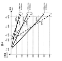
この可変分散スロープ補償器(11)中の第一の分散補償ファイバ群(21−1、2、3)と、第二の分散補償ファイバ群(22−1、2、3)の特性は下記のように設計されている。伝送ファイバの分散係数は図2に示すように、ゼロ分散波長がλ0aからλ0bの間でばらついているものとする。また、WDM信号波長の帯域は最短波長側をλL、最長波長側をλUとする。ここでゼロ分散波長が平均的な特性よりも短波長側に位置するファイバaと、ゼロ分散波長が平均的な特性よりも長波長側に位置するファイバbを考える。帯域内の代表波長λxにおける分散係数はファイバa及びファイバbのそれぞれにおいてDa及びDb(ps/nm/km)であるものとする。また、分散スロープはファイバa及びファイバbいずれの場合もS(ps/nm/nm/km)であるものとする。 The characteristics of the first dispersion compensating fiber group (21-1, 2, 3) and the second dispersion compensating fiber group (22-1, 2, 3) in the variable dispersion slope compensator (11) are as follows. Designed to be As shown in FIG. 2, the dispersion coefficient of the transmission fiber is such that the zero dispersion wavelength varies between λ0a and λ0b. Further, the WDM signal wavelength band is λL on the shortest wavelength side and λU on the longest wavelength side. Here, a fiber a in which the zero dispersion wavelength is located on the shorter wavelength side than the average characteristic and a fiber b in which the zero dispersion wavelength is located on the longer wavelength side than the average characteristic are considered. It is assumed that the dispersion coefficients at the representative wavelength λx in the band are Da and Db (ps / nm / km) in the fibers a and b, respectively. Further, the dispersion slope is assumed to be S (ps / nm / nm / km) for both the fiber a and the fiber b.
ここでDCFaはファイバaの分散及び分散スロープを補償するように、つまり、代表波長λxでの分散係数が−Daとなるように、また分散スロープが−Sとなるように設計する。また、DCFbはファイバbの分散及び分散スロープを補償するように、つまり、代表波長λxでの分散係数が−Dbとなるように、また分散スロープが−Sとなるように設計する。 Here, the DCFa is designed so as to compensate for the dispersion and dispersion slope of the fiber a, that is, so that the dispersion coefficient at the representative wavelength λx becomes −Da and the dispersion slope becomes −S. The DCFb is designed to compensate for the dispersion and dispersion slope of the fiber b, that is, so that the dispersion coefficient at the representative wavelength λx is −Db and the dispersion slope is −S.
言い換えると、光ファイバの分散スロープ(単位:ps/nm/nm/km)を分散係数(単位:ps/nm/km)で除した値で定義される相対分散スロープRDS(単位:/nm)を用いた場合に、DCFaは代表波長λxでの相対分散スロープRDSがRDSa=S/Daとなるように、DCFbは代表波長λxでの相対分散スロープRDSがRDSb=S/Dbとなるように設計される。 In other words, the relative dispersion slope RDS (unit: / nm) defined by the value obtained by dividing the dispersion slope (unit: ps / nm / nm / km) of the optical fiber by the dispersion coefficient (unit: ps / nm / km). When used, DCFa is designed so that the relative dispersion slope RDS at the representative wavelength λx is RDSa = S / Da, and DCFb is designed so that the relative dispersion slope RDS at the representative wavelength λx is RDSb = S / Db. The
具体的な数値例を図3に示す。伝送ファイバの分散は1540nm(λ0a)から1560nm(λ0b)の間でばらついているものとし、分散スロープは0.07ps/nm/nm/kmとする。また、WDM信号波長の帯域は最短波長側を1570nm(λL)、最長波長側を1610nm(λU)とし、信号帯域内の代表波長は、帯域の中心である1590nm(λx)とする。ここでファイバaのゼロ分散波長が分布の最短波側(1540nm)に位置するものとし、またファイバbのゼロ分散波長が分布の最長波長側(1560nm)に位置するものとする。この場合において、DCFaは分散スロープが−0.07ps/nm/nm/km、代表波長1590nmでの分散量が−3.5ps/nm/kmとなるように設計される。また、DCFbは分散スロープが−0.07ps/nm/nm/km、代表波長1590nmでの分散量が−2.1ps/nm/kmとなるように設計される。相対分散スロープRDSを用いて表現すると、図1中の数値例に示されるように、DCFa(21−1、2、3)のRDSは0.02/nm(=0.07/3.5)となるように設計される。また、DCFb(22−1、2、3)のRDSは0.033/nm(=0.07/2.1)となるように設計される。 Specific numerical examples are shown in FIG. The dispersion of the transmission fiber is assumed to vary between 1540 nm (λ0a) and 1560 nm (λ0b), and the dispersion slope is 0.07 ps / nm / nm / km. The WDM signal wavelength band is 1570 nm (λL) on the shortest wavelength side and 1610 nm (λU) on the longest wavelength side, and the representative wavelength in the signal band is 1590 nm (λx) which is the center of the band. Here, it is assumed that the zero dispersion wavelength of the fiber a is located on the shortest wave side (1540 nm) of the distribution, and the zero dispersion wavelength of the fiber b is located on the longest wavelength side (1560 nm) of the distribution. In this case, DCFa is designed so that the dispersion slope is -0.07 ps / nm / nm / km and the dispersion amount at the representative wavelength of 1590 nm is -3.5 ps / nm / km. DCFb is designed such that the dispersion slope is -0.07 ps / nm / nm / km and the dispersion amount at the representative wavelength of 1590 nm is -2.1 ps / nm / km. When expressed using the relative dispersion slope RDS, as shown in the numerical example in FIG. 1, the RDS of DCFa (21-1, 2, 3) is 0.02 / nm (= 0.07 / 3.5). Designed to be The RDS of DCFb (22-1, 2, 3) is designed to be 0.033 / nm (= 0.07 / 2.1).
さらに、DCFa群(21−1、2、3)及びDCFb群(22−1、2、3)を構成する各ファイバは、代表波長における分散量(分散補償量)が、ある規定の分散ステップ値Ds(ps/nm)に対してM倍(M=1、2、3。。。)となるように、あるいは2のN乗倍(N=1、2、3。。。)となるように設定されている。 具体的な数値例を挙げると、分散ステップ値(Ds)−50ps/nmに対して、2のN乗倍(N=1、2、3)つまり1倍、2倍、4倍となるように分散量を設定する場合を考える。図1の数値例に示されるように、DCFa群の各分散補償ファイバ(21−1、2、3)の代表波長1590nmにおける分散量はそれぞれ、−50、−100、−200ps/nmとなる。同様にDCFb群の各分散補償ファイバ(22−1、2、3)の代表波長1590nmにおける分散量もそれぞれ−50、−100、−200ps/nmとなる。この数値例におけるDCFa(21−1、2、3)及びDCFb(22−1、2、3)の分散プロファイルを図4に、代表特性値の一覧を図5に示す。 Furthermore, each of the fibers constituting the DCFa group (21-1, 2, 3) and the DCFb group (22-1, 2, 3) has a dispersion amount (dispersion compensation amount) at a representative wavelength having a certain dispersion step value. D times (ps / nm) M times (M = 1, 2, 3,...) Or 2 times N times (N = 1, 2, 3,...) Is set. As a specific numerical example, the dispersion step value (Ds) −50 ps / nm is 2 N times (N = 1, 2, 3), that is, 1 time, 2 times, 4 times. Consider the case of setting the amount of dispersion. As shown in the numerical example of FIG. 1, the dispersion amounts at the representative wavelength of 1590 nm of the dispersion compensating fibers (21-1, 2, 3) of the DCFa group are −50, −100, and −200 ps / nm, respectively. Similarly, the dispersion amounts at the representative wavelength of 1590 nm of the dispersion compensating fibers (22-1, 2, 3) of the DCFb group are -50, -100, and -200 ps / nm, respectively. FIG. 4 shows a dispersion profile of DCFa (21-1, 2, 3) and DCFb (22-1, 2, 3) in this numerical example, and FIG. 5 shows a list of representative characteristic values.
ここで、以上説明してきたように設計されたDCFa(21−1、2、3)及びDCFb(22−1、2、3)とから構成された、図1に示される可変分散スロープ補償器(11)において、各光スイッチ(23)を任意に切り替える場合を考える。光スイッチ(23)を切り替えることにより各DCF(21−1、2、3及び22−1、2、3)の接続組合せは自在に変化し、入力ポート(25)から出力ポート(26)の間の分散量は変化する。その一方で、異なる接続組合せにおいても、代表波長λxでの分散量が等しくなる組合せが複数存在する。例えば分散量−100ps/nmを実現する組合せは、分散量−100ps/nmのDCFa(21−2)単独の場合、あるいは分散量がいずれも−50ps/nmのDCFa(21−1)とDCFb(22−1)を組み合わせた場合、あるいは分散量−100ps/nmのDCFb(22−2)単独の場合、と3通りの場合が可能である。 Here, the variable dispersion slope compensator (shown in FIG. 1) composed of DCFa (21-1, 2, 3) and DCFb (22-1, 2, 3) designed as described above. 11) Consider a case where each optical switch (23) is arbitrarily switched. By switching the optical switch (23), the connection combinations of the DCFs (21-1, 2, 3 and 22-1, 2, 3) can be freely changed, and between the input port (25) and the output port (26). The amount of dispersion varies. On the other hand, even in different connection combinations, there are a plurality of combinations having the same dispersion amount at the representative wavelength λx. For example, a combination that realizes a dispersion amount of −100 ps / nm is a DCFa (21-2) with a dispersion amount of −100 ps / nm alone, or DCFa (21-1) and DCFb (with a dispersion amount of −50 ps / nm). When combining 22-1) or DCFb (22-2) having a dispersion amount of −100 ps / nm alone, three cases are possible.
表記の簡略化の為に、こうした組合せを識別する記号として、各組合せを「代表波長での全分散量の絶対値、d」と「選択したDCFbの全分散量を分散ステップDsで除した値、k」の二つの量を用いて「d ps−#k」と表すものとする。例えば、前述の分散量分散量−100ps/nmを実現する組合せは、分散量−100ps/nmのDCFa(21−2)単独の場合が「100ps−#0」と表記され、また、分散量がいずれも−50ps/nmのDCFa(21−1)とDCFb(22−1)を組み合わせた場合は「100ps−#1」と表記され、また、分散量−100ps/nmのDCFb(22−2)単独の場合が「100ps−#2」と表記される。 For simplification of description, as a symbol for identifying such combinations, each combination is expressed as “absolute value of total dispersion amount at representative wavelength, d” and “a value obtained by dividing the total dispersion amount of the selected DCFb by the dispersion step Ds”. , K ”, and“ d ps- # k ”. For example, in the combination that realizes the dispersion amount dispersion of −100 ps / nm described above, the DCFa (21-2) alone having a dispersion amount of −100 ps / nm is expressed as “100 ps- # 0”, and the dispersion amount is In any case, when DCFa (21-1) and DCFb (22-1) of −50 ps / nm are combined, it is expressed as “100 ps- # 1”, and DCFb (22-2) of dispersion amount −100 ps / nm A single case is described as “100 ps- # 2”.
光スイッチ(23)を切替えた時の各分散補償ファイバ(21−1、2、3及び22−1、2、3)の接続組合せを、この表記「d ps−#k」を用いて整理すると、図6のようになる。図中の○印は該当する分散補償ファイバを選択することを、×印は該当する分散補償ファイバを選択しないことを(つまり、スルーファイバ側を選択することを)意味する。
ここで、前述したように、DCFa(21−1、2、3)及びDCFb(22−1、2、3)の相対分散スロープ値が互いに異なる為、DCFの組合せを変化させると、(つまり、「選択したDCFbの全分散量を分散ステップDsで除した値、k」の値を変化させると、)その接続組合せにおける相対分散スロープRDS値を変化させることが可能となる。つまり、図6において全分散量が同一の組合せ間において、代表波長1590nmでの分散量はいずれも等しくなる一方で、帯域の両端1570nm及び1610nmでの分散量は可変することが可能となる。例えば、全分散量の絶対値d=−100ps/nmの場合を見ると、「100ps−#0」、「100ps−#1」、「100ps−#2」いずれの組合せにおいても代表波長1590nmでの分散量は−100ps/nmであるが、1570nmでの分散量は「100ps−#0」、「100ps−#1」、「100ps−#2」それぞれの場合で、−60、−46.7、−33.3ps/nmとなり、kの値の増加と共に減少していく。一方で1610nmでの分散量は「100ps−#0」、「100ps−#1」、「100ps−#2」それぞれの場合で、−140、−153.3、−166.7ps/nmsとなり、kの値の増加と共に増大していく。つまりkの値を変えることにより相対分散スロープRDSを変化させることが可能である。
The connection combination of the dispersion compensating fibers (21-1, 2, 3 and 22-1, 2, 3) when the optical switch (23) is switched is rearranged using this notation “d ps- # k”. As shown in FIG. In the figure, a circle indicates that the corresponding dispersion compensation fiber is selected, and a cross indicates that the corresponding dispersion compensation fiber is not selected (that is, the through fiber side is selected).
Here, as described above, since the relative dispersion slope values of DCFa (21-1, 2, 3) and DCFb (22-1, 2, 3) are different from each other, changing the combination of DCFs (that is, When the value of “the value obtained by dividing the total dispersion amount of the selected DCFb by the dispersion step Ds, k” is changed), the relative dispersion slope RDS value in the connection combination can be changed. That is, in FIG. 6, between the combinations having the same total dispersion amount, the dispersion amounts at the representative wavelength of 1590 nm are equal, while the dispersion amounts at both ends of the
前述したように、DCFa群(21−1、2、3)及びDCFb群(22−1、2、3)を構成する各ファイバは、代表波長における分散量(分散補償量)が、ある規定の分散ステップ値Ds(ps/nm)に対してM倍(M=1、2、3。。。)となるように、あるいは2のN乗倍(N=1、2、3。。。)となるように設定されている。従って、DCFa群(21−1、2、3)から適切な1つあるいは複数のファイバを選択してそれらを接続することにより、総分散量(d−k×Ds)を実現することが可能であり。同様にDCFb群(22−1、2、3)から適切な1つあるいは複数のファイバを選択してそれらを接続することにより、総分散量(k×Ds)を実現することが可能である。つまり、これらのファイバを接続することにより総分散量dの状態で、kの値を買えることにより分散スロープを変化することが可能となる。分散スロープ補償器内の全DCFの総量を抑制するためには、DCFa群(21−1、2、3)及びDCFb群(22−1、2、3)を構成する各ファイバを、代表波長における分散量(分散補償量)が、ある規定の分散ステップ値Ds(ps/nm)に対してあるいは2のN乗倍(N=1、2、3。。。)となるように設定することが効果的である。 As described above, each fiber constituting the DCFa group (21-1, 2, 3) and the DCFb group (22-1, 2, 3) has a certain amount of dispersion (dispersion compensation amount) at a certain wavelength. M times the dispersion step value Ds (ps / nm) (M = 1, 2, 3,...), Or N times 2 (N = 1, 2, 3,...). It is set to be. Therefore, it is possible to realize the total dispersion amount (d−k × Ds) by selecting an appropriate fiber or fibers from the DCFa group (21-1, 2, 3) and connecting them. Yes. Similarly, it is possible to realize the total dispersion amount (k × Ds) by selecting one or a plurality of appropriate fibers from the DCFb group (22-1, 2, 3) and connecting them. That is, by connecting these fibers, the dispersion slope can be changed by purchasing the value of k in the state of the total dispersion amount d. In order to suppress the total amount of all the DCFs in the dispersion slope compensator, each fiber constituting the DCFa group (21-1, 2, 3) and the DCFb group (22-1, 2, 3) is set at a representative wavelength. The dispersion amount (dispersion compensation amount) may be set so as to be a predetermined dispersion step value Ds (ps / nm) or a power of 2 times N (N = 1, 2, 3,...). It is effective.
この相対分散スロープRDSの変化の様子は図7に示す分散プロファイルでより明らかとなる。「代表波長での全分散量の絶対値、d」を固定した状態で、「選択したDCFbの全分散量を分散ステップDsで除した値、k」を変化させると、代表波長での分散量は変わらずに、分散スロープのみが変化していく。例えば、「100ps−#0」、「100ps−#1」、「100ps−#2」について言えば、代表波長1590nmでの分散量−100ps/nmを保持したまま、kの値を0、1、2と増加させていくと、分散スロープがより急峻になっていく様子が観測される。この現象は「代表波長での全分散量の絶対値、d」が100ps/nm以外の場合でも同様であり、やはりkを増加させていくと、代表波長での分散量を保持したまま分散スロープのみが急峻となっていく。つまり本発明の図1の構成によって、光スイッチ(23)を切り替えることにより、分散のみならず分散スロープまでもが可変となる、可変分散スロープ補償器が実現される。 The state of the change of the relative dispersion slope RDS becomes more apparent from the dispersion profile shown in FIG. When “the absolute value of the total dispersion amount at the representative wavelength, d” is fixed and “the value obtained by dividing the total dispersion amount of the selected DCFb by the dispersion step Ds, k” is changed, the dispersion amount at the representative wavelength Only the dispersion slope changes. For example, regarding “100 ps- # 0”, “100 ps- # 1”, “100 ps- # 2”, the value of k is set to 0, 1, while maintaining the dispersion amount −100 ps / nm at the representative wavelength of 1590 nm. As the value is increased to 2, it is observed that the dispersion slope becomes steeper. This phenomenon is the same even when “the absolute value of the total dispersion amount at the representative wavelength, d” is other than 100 ps / nm. If k is increased, the dispersion slope is maintained while maintaining the dispersion amount at the representative wavelength. Only becomes steep. In other words, the configuration of FIG. 1 of the present invention realizes a variable dispersion slope compensator in which not only dispersion but also dispersion slope is variable by switching the optical switch (23).
図1の構成では、分散ステップ値(Ds)−50ps/nmに対して、2のN乗倍(N=1、2、3)つまり1倍、2倍、4倍となるように分散量を設定し、DCFa群の各分散補償ファイバ(21−1、2、3)の代表波長1590nmにおける分散量はそれぞれ、−50、−100、−200ps/nmとした。この分散ステップ値(Ds)を減少させると、より精度の高い可変分散補償器が実現される。例えば、分散ステップ値(Ds)を−25ps/nmとし、さらにDCFa群及びDCFb群をそれぞれ4本のDCFから構成されれるようにし、2のN乗倍(N=1、2、3、4)つまり1倍、2倍、4倍、8倍となるように分散量を設定して、各分散補償ファイバの代表波長1590nmにおける分散量を図8に示すようにそれぞれ、−25、−50、−100、−200ps/nmとすると、図9に示すように代表波長での分散量のみならず、分散スロープについても実現可能な分散プロファイルが増大し、より精度の高い分散スロープ補償が実現される。 In the configuration of FIG. 1, the dispersion amount is set so that the dispersion step value (Ds) −50 ps / nm is 2 N times (N = 1, 2, 3), that is, 1 time, 2 times, and 4 times. The dispersion amounts at the representative wavelength of 1590 nm of the dispersion compensating fibers (21-1, 2, 3) of the DCFa group were set to −50, −100, and −200 ps / nm, respectively. When the dispersion step value (Ds) is decreased, a variable dispersion compensator with higher accuracy is realized. For example, the dispersion step value (Ds) is set to −25 ps / nm, and the DCFa group and the DCFb group are each composed of four DCFs, so that the N power of 2 (N = 1, 2, 3, 4). That is, the dispersion amount is set so as to be 1, 2 times, 4 times, and 8 times, and the dispersion amounts at the representative wavelength of 1590 nm of each dispersion compensating fiber are −25, −50, −, respectively, as shown in FIG. Assuming 100 and −200 ps / nm, as shown in FIG. 9, not only the dispersion amount at the representative wavelength but also the dispersion profile that can be realized for the dispersion slope increases, and dispersion slope compensation with higher accuracy is realized.
また、図1及び図3の例ではファイバaのゼロ分散波長を分布の最短波側(1540nm)に位置するものとし、またファイバbのゼロ分散波長を分布の最長波長側(1560nm)に位置するものとして、これに対応したDCFa及びDCFbの特性値を決定した。しかしながら、図2に示すように、ファイバaのゼロ分散波長が分布の短波長領域内のいずれかの波長上に位置し、ファイバbのゼロ分散波長が分布の長波長領域内のいずれかの波長上に位置するものとして、これに対応したこれに対応したDCFa及びDCFbの特性値を決定しても本特許は有効である。即ち、ファイバの分散スロープ(単位:ps/nm/nm/km)を分散係数(単位:ps/nm/km)で除した値で定義される相対分散スロープRDS(単位:/nm)を用いた場合に、DCFaは代表波長λxでの相対分散スロープRDSがRDSa=S/Daとなるように、DCFbは代表波長λxでの相対分散スロープRDSがRDSb=S/Dbとなるように設計し、RDSa<RDSbの関係を維持していれば本特許は有効となる。つまり、ファイバaのゼロ分散波長が1545nm、ファイバbのゼロ分散波長が分1555nmに位置するものとして、これに対応したこれに対応したDCFa及びDCFbの特性値を決定しても本特許は有効であり、設計の自由度は向上する。 1 and 3, the zero dispersion wavelength of the fiber a is positioned on the shortest wave side (1540 nm) of the distribution, and the zero dispersion wavelength of the fiber b is positioned on the longest wavelength side (1560 nm) of the distribution. As a thing, the characteristic value of DCFa and DCFb corresponding to this was determined. However, as shown in FIG. 2, the zero dispersion wavelength of the fiber a is located on any wavelength in the short wavelength region of the distribution, and the zero dispersion wavelength of the fiber b is any wavelength in the long wavelength region of the distribution. Even if the corresponding characteristic values of DCFa and DCFb corresponding to this are determined as those located above, this patent is effective. That is, the relative dispersion slope RDS (unit: / nm) defined by the value obtained by dividing the fiber dispersion slope (unit: ps / nm / nm / km) by the dispersion coefficient (unit: ps / nm / km) was used. In this case, DCFa is designed so that the relative dispersion slope RDS at the representative wavelength λx is RDSa = S / Da, and DCFb is designed so that the relative dispersion slope RDS at the representative wavelength λx is RDSb = S / Db. <This patent is effective if the relationship of RDSb is maintained. That is, assuming that the zero dispersion wavelength of the fiber a is 1545 nm and the zero dispersion wavelength of the fiber b is 1555 nm, this patent is effective even if the corresponding characteristic values of DCFa and DCFb are determined. Yes, the degree of design freedom is improved.
また、ここまでの実施例中の数値例では、代表波長(λx)を信号波長の中心波長(1590nm)としていたが、信号波長近傍の例えばITU−Grid波長である1589.57nmや1590.41nmを代表波長としても本特許は適用可能であり、また中心近傍でなくても長波長側の例えば1595nmといった任意の波長や、短波長側の任意の波長を代表波長としても本特許の有効性は損なわれない。 Further, in the numerical examples in the embodiments so far, the representative wavelength (λx) is the center wavelength (1590 nm) of the signal wavelength. However, for example, ITU-Grid wavelengths near 1589.57 nm and 1590.41 nm are used. This patent can be applied as a representative wavelength, and even if it is not near the center, the validity of this patent is impaired even if an arbitrary wavelength such as 1595 nm on the long wavelength side or an arbitrary wavelength on the short wavelength side is used as the representative wavelength. I can't.
また、ここまでの実施例中の数値例では、分散ステップ値(Ds)−50ps/nmに対して、2のN乗倍(N=1、2、3)つまり1倍、2倍、4倍となるように各DCFの分散量を設定したが、2のM倍(M=1、2、3。。。)つまり1倍、2倍、3倍としても本特許は適用可能である。また分散ステップ値(Ds)−50ps/nmに対して、厳密に2のN乗倍(N=1、2、3)、あるいは2のM倍(M=1、2、3。。。)でなくても、その近傍の値の分散量とすることによっても本特許は適用可能である。 Further, in the numerical examples in the embodiments so far, the dispersion step value (Ds) −50 ps / nm is 2 N times (N = 1, 2, 3), that is, 1 time, 2 times, 4 times. The dispersion amount of each DCF is set so as to be, but this patent is applicable to M times 2 (M = 1, 2, 3,...), That is, 1 time, 2 times, and 3 times. In addition, with respect to the dispersion step value (Ds) −50 ps / nm, strictly N times N (N = 1, 2, 3) or M times 2 (M = 1, 2, 3, ..). Even if it is not, this patent can also be applied by setting the amount of dispersion in the vicinity thereof.
実際の分散補償ファイバでは分散の波長依存性は厳密に直線ではなく、分散スロープに加えて、上に凸あるいは下に凸となる高次の波長依存特性が存在するため、さらに高精度の分散補償を必要とする場合にはこの影響を考慮する必要があるが、この場合においても分散スロープの成分は、本特許で高精度に補償可能であり、本特許の有効性は損なわれない。 In an actual dispersion compensation fiber, the wavelength dependence of dispersion is not strictly a straight line, and in addition to the dispersion slope, there is a higher-order wavelength dependence characteristic that is convex upward or convex downward. However, even in this case, the dispersion slope component can be compensated with high accuracy in this patent, and the effectiveness of this patent is not impaired.
以上説明してきたように、相対分散スロープRDS値の異なる第一の分散補償ファイバ群、及び第二の分散補償ファイバ群、及びこれらの分散補償ファイバ群の任意の接続組合せを実現するための光スイッチ群あるいはパッチケーブル群とにより、伝送ファイバのゼロ分散波長かつ分散スロープに呼応して分散補償器の補償する分散スロープを可変できる、可変分散スロープ補償器が構成可能となる。 As described above, the first dispersion compensating fiber group and the second dispersion compensating fiber group having different relative dispersion slope RDS values, and an optical switch for realizing an arbitrary connection combination of these dispersion compensating fiber groups By using the group or the patch cable group, it is possible to configure a variable dispersion slope compensator that can vary the dispersion slope compensated by the dispersion compensator in response to the zero dispersion wavelength and dispersion slope of the transmission fiber.
さらに、第一の分散補償ファイバ群、及び第二の分散補償ファイバ群を構成する各分散補償ファイバにおいて、それぞれの代表波長における分散補償量が、既定の分散補償ステップ量に対して整数倍、あるいは2のN乗(Nは整数)倍となるように設計することにより、高精度にスロープを調整可能な可変分散スロープ補償器を構成可能である。 Further, in each dispersion compensation fiber constituting the first dispersion compensation fiber group and the second dispersion compensation fiber group, the dispersion compensation amount at each representative wavelength is an integral multiple of a predetermined dispersion compensation step amount, or A variable dispersion slope compensator capable of adjusting the slope with high accuracy can be constructed by designing the power to be N times N (N is an integer).
さらに、想定される伝送ファイバのゼロ分散波長ばらつきに対して、ゼロ分散波長が分布中心より短波長側に位置した場合の伝送ファイバのRDS値と、第一の分散補償ファイバ群のRDS値とを一致させ、また、ゼロ分散波長が分布中心より長波長側に位置した場合の伝送ファイバのRDS値と、第二の分散補償ファイバ群のRDS値とを一致させることにより、広範な範囲にスロープを調整可能な可変分散スロープ補償器を構成可能である。 Furthermore, with respect to the assumed zero dispersion wavelength variation of the transmission fiber, the RDS value of the transmission fiber when the zero dispersion wavelength is located on the short wavelength side from the distribution center and the RDS value of the first dispersion compensation fiber group are: In addition, by matching the RDS value of the transmission fiber when the zero dispersion wavelength is located on the long wavelength side from the center of the distribution, and the RDS value of the second dispersion compensation fiber group, the slope can be expanded over a wide range. An adjustable variable dispersion slope compensator can be constructed.
また、本特許における分散補償ファイバ群は二つに限定されるものではなく、三群以上の分散補償ファイバ群を用いることにより、より高精度の補償が可能となり、設計自由度も向上する。 In addition, the dispersion compensation fiber group in this patent is not limited to two. By using three or more dispersion compensation fiber groups, more accurate compensation is possible and the degree of freedom in design is improved.
本発明の第2の実施例を図10、図11を用いて説明する。図10は本発明の第1の実施例である、可変分散スロープ補償器(11)を含む多中継伝送システムである。送信器(12)は合波器(13)によって多重されてWDM信号を形成し、光アンプ(14−1)で増幅された後に中継伝送路に入射される。伝送路は伝送光ファイバ(15−1、2。。。)、可変分散スロープ補償器(11−1、2。。。)、及び光アンプ(14−1、2。。。)とから構成され、中継伝送路を経たWDM信号は、分波器(16)で分波されて受信器(17)に達する。各可変分散スロープ補償器(11−1、2。。。)の分散補償量は、分散補償量設定手段(18)によって算出され、遠隔設定される。 A second embodiment of the present invention will be described with reference to FIGS. FIG. 10 shows a first embodiment of the present invention, which is a multi-relay transmission system including a variable dispersion slope compensator (11). The transmitter (12) is multiplexed by the multiplexer (13) to form a WDM signal, amplified by the optical amplifier (14-1), and then incident on the relay transmission line. The transmission path is composed of transmission optical fibers (15-1, 2...), Variable dispersion slope compensators (11-1, 2...), And optical amplifiers (14-1, 2...). The WDM signal that has passed through the relay transmission path is demultiplexed by the demultiplexer (16) and reaches the receiver (17). The dispersion compensation amount of each variable dispersion slope compensator (11-1, 2,...) Is calculated by the dispersion compensation amount setting means (18) and set remotely.
ここで各可変分散スロープ補償器(11)の分散補償量は図11に示すフローによって設定される。ここで、該当するスパン番号i(初期値1)に対して、可変分散スロープ補償器(11−i)の分散補償量を設定する場合を考える。まず、直前の伝送ファイバ(15−i)までの総分散量Dti(λ)を算出する。総分散量Dti(λ)は図10の構成の場合、可変分散スロープ補償器(11−i)の直前までの伝送ファイバの分散量の総和Df1(λ)+Df2(λ)+。。。+Dfi(λ)と、可変分散スロープ補償器(11−i)の直前までの可変部分散スロープ補償器の分散設定量の総和Dd1(λ)+Dd2(λ)+。。。+Dd(i−1)(λ)の和によって算出される。 Here, the dispersion compensation amount of each variable dispersion slope compensator (11) is set by the flow shown in FIG. Here, consider a case where the dispersion compensation amount of the variable dispersion slope compensator (11-i) is set for the corresponding span number i (initial value 1). First, the total dispersion amount Dti (λ) up to the immediately preceding transmission fiber (15-i) is calculated. In the case of the configuration of FIG. 10, the total dispersion amount Dti (λ) is the total sum Df1 (λ) + Df2 (λ) + of the dispersion amount of the transmission fiber until just before the variable dispersion slope compensator (11-i). . . + Dfi (λ) and the sum Dd1 (λ) + Dd2 (λ) + of the dispersion set amount of the variable part dispersion slope compensator up to immediately before the variable dispersion slope compensator (11-i). . . Calculated by the sum of + Dd (i−1) (λ).
伝送ファイバの分散量の総和Df1(λ)、Df2(λ)。。。Dfi(λ)は事前に測定されたフィールドデータを分散補償量設定手段(18)に手入力してもよいし、事前に測定されたフィールドデータを管理するテーブル領域を分散補償量設定手段(18)の内部あるいは分散補償量設定手段(18)がアクセス可能なエリアに設置し、このテーブルを参照することによって導出してもよい。また、別途分散測定手段を設けて、オンタイムで分散データを取得して、この値を用いて伝送ファイバの分散量を求めてもよい。また、直前までの可変分散スロープ補償器の分散設定量Dd1(λ)、Dd2(λ)、。。。、Dd(i−1)(λ)は、これまでに算出して実際に設定した分散設定量を分散補償量設定手段(18)の内部に保存しておくことによって取得可能である。 Total sum Df1 (λ) and Df2 (λ) of the dispersion amount of the transmission fiber. . . Dfi (λ) may be manually input field data measured in advance to the dispersion compensation amount setting means (18), or a table area for managing field data measured in advance is set as the dispersion compensation amount setting means (18). ) Or in an area accessible by the dispersion compensation amount setting means (18) and may be derived by referring to this table. Alternatively, a dispersion measurement unit may be provided separately to obtain dispersion data on time, and the dispersion amount of the transmission fiber may be obtained using this value. Also, dispersion setting amounts Dd1 (λ), Dd2 (λ) of the variable dispersion slope compensator until just before. . . , Dd (i−1) (λ) can be obtained by storing the dispersion setting amount calculated and actually set so far in the dispersion compensation amount setting means (18).
次に、代表波長での総分散量Dti(λx)、分散ステップ量Dsに対して、N×Ds < Dti(λx) < (N+1)×Ds を満たすゼロまたは正の自然数Nを求める。このことは、可変分散スロープ補償器(13)において設定可能な「代表波長での全分散量の絶対値、d」の中から、代表波長での総分散量Dti(λx)に最も近い値を選択することを意味している。 Next, a zero or positive natural number N satisfying N × Ds <Dti (λx) <(N + 1) × Ds is obtained with respect to the total dispersion amount Dti (λx) and dispersion step amount Ds at the representative wavelength. This means that a value closest to the total dispersion amount Dti (λx) at the representative wavelength is selected from “absolute value of total dispersion amount at the representative wavelength, d” that can be set in the variable dispersion slope compensator (13). Means to choose.
次に、n=Nとした後に、DCFaの代表波長での分散量を(n−k)×Ds、DCFbの代表波長での分散量をk×Dsとした時の接続組合せにおいて、分散量Ddi(λ)を算出する。この作業は、図6中の識別番号(n×Ds)ps−#kを選択することに相当する。 Next, after setting n = N, the dispersion amount Ddi in the connection combination when the dispersion amount at the representative wavelength of DCFa is (n−k) × Ds and the dispersion amount at the representative wavelength of DCFb is k × Ds. (Λ) is calculated. This operation corresponds to selecting the identification number (n × Ds) ps- # k in FIG.
ここで分散補償後の累積分散量の2乗和を最短波長の場合と最長波長の場合でそれぞれ算出し、さらにその和、T=(Dti(λL)+Ddi(λL))^2 + (Dti(λU)+Ddi(λU))^2を算出する。 Here, the sum of squares of the accumulated dispersion amount after dispersion compensation is calculated for each of the shortest wavelength and the longest wavelength, and the sum T = (Dti (λL) + Ddi (λL)) ^ 2 + (Dti (λU) + Ddi (λU)) ^ 2 is calculated.
算出したTはn、及びkの組合せとともにメモリに保存しておき、同様にして、n=N、かつk=0、1、2。。。nの各組み合わせにおけるTを算出する。また、同様にしてn=N+1、かつk=0、1、2。。。nの各組合せにおけるTを算出する。 The calculated T is stored in the memory together with the combination of n and k, and similarly, n = N and k = 0, 1, 2, and so on. . . T in each combination of n is calculated. Similarly, n = N + 1 and k = 0, 1, 2, and so on. . . T in each combination of n is calculated.
各組合せにおけるTの算出が終了したら、Tを最小とするn、kの組合せを検索し、この組合せを可変分散スロープ補償器(11−i)の設定量とする。つまりd=n×Dsとなる、「d ps−#k」の組み合わせを設定する。 When the calculation of T in each combination is completed, a combination of n and k that minimizes T is searched, and this combination is set as the set amount of the variable dispersion slope compensator (11-i). That is, a combination of “d ps- # k” that sets d = n × Ds is set.
以上の工程を、iを1つづつ増加させて逐次的に算出、設定し、全スパンにおいて可変分散スロープ補償器(13)の設定が終了すると、設定フローの終了となる。 The above steps are sequentially calculated and set by increasing i one by one, and when the setting of the variable dispersion slope compensator (13) is completed in all spans, the setting flow ends.
以上説明してきたフローは図12のように、直前の伝送ファイバまでの総分散量Dti(λ)を100%補償する場合の特性に対して、可変分散スロープ補償器(13)において設定可能な組合せの中から代表波長(λx)での分散量が最も近くなる2つのグループ(分散量N×Dsのグループ、及び分散量(N+1)×Dsのグループ)を選択し、さらに、これらの2つのグループに属する「(N×Ds)ps−#0」、「(N×Ds)ps−#1」、...「(N×Ds)ps−#N」及び「((N+1)×Ds)ps−#0」、「((N+1)×Ds)ps−#1」、...「((N+1)×Ds)ps−#N+1」の中から、両端の波長(λL及びλU)での二乗誤差が最も小さくなる組合せを選択することに相当する。このように、簡易なアルゴリズムにて可変分散スロープ補償器(13)において設定可能な組み合わせの中から帯域中での補償誤差が最小(あるいはほぼ最小)の組合せを選択することが可能となる。 上記フローによって選択された場合の本特許の効果についてシミュレーションした場合の結果を以下に示す。図10に示す伝送システム構成において、中継数を10とし、伝送ファイバ(15−1、2、。。。10)のゼロ分散波長は1540nm(λ0a)から1560nm(λ0b)の間の一様分布乱数によって設定した。また伝送ファイバ(15−1、2、。。。10)のファイバ長も60kmから90kmの間の一様分布乱数によって設定した。以上の10中継伝送システムを1000パターン生成し、各パターンに図11のフローを適用し、各分散スロープ補償器の分散量を設定し、各分散スロープ補償器出力での残留分散量を算出した。また、分散スロープは0.07ps/nm/nm/kmとし、WDM信号波長の帯域は最短波長側を1570nm(λL)、最長波長側を1610nm(λU)とし、信号帯域内の代表波長は、帯域の中心である1590nm(λx)とした。DCFa及びDCFbは、ゼロ分散波長が分布の最短波側(1540nm)および最長波長側(1560nm)に位置する場合のファイバを補償するように設計し、また分散ステップは50ps/nmとした。つまり各DCFa及びDCFbの特性値は前述の図5に示す値であり、図1に示す構成の可変分散スロープ補償器とした。
The flow described above is a combination that can be set in the variable dispersion slope compensator (13) with respect to the characteristics in the case where 100% of the total dispersion amount Dti (λ) up to the previous transmission fiber is compensated as shown in FIG. 2 groups (dispersion amount N × Ds group and dispersion amount (N + 1) × Ds group) having the closest dispersion amount at the representative wavelength (λx) are selected from the above two groups. “(N × Ds)
1000パターン計算した分散補償の一例を図13及び図14に示す。図13(a)及び図14(a)は各スパン毎の、分散スロープ補償器出力での残留分散量であり、図13(b)及び図14(b)には各スパンでの(乱数で与えられた)ファイバ長とゼロ分散波長、及び図11のフローによって選択されたDCF「d ps−#k」のd値及びk値を示す。図13(a)及び図14(a)には最短波長(1570nm)及び最長波長(1610nm)のそれぞれの値をプロットした。また、図13(a)及び図14(a)には比較のために従来方式、つまり伝送路の平均特性(ゼロ分散波長1550nm)に相当する、単一の相対分散スロープRDSを持つ1種類のDCFを分散ステップ50ps/nmにおいて調整した場合の結果を併記した。 An example of dispersion compensation calculated for 1000 patterns is shown in FIGS. FIGS. 13 (a) and 14 (a) show the residual dispersion amount at the output of the dispersion slope compensator for each span, and FIGS. 13 (b) and 14 (b) show (random numbers) in each span. FIG. 11 shows the fiber length and zero dispersion wavelength (given) and the d and k values of the DCF “d ps- # k” selected by the flow of FIG. In FIG. 13A and FIG. 14A, the values of the shortest wavelength (1570 nm) and the longest wavelength (1610 nm) are plotted. For comparison, FIGS. 13 (a) and 14 (a) show one type having a single relative dispersion slope RDS corresponding to the conventional method, that is, the average characteristic of the transmission line (zero dispersion wavelength 1550 nm). The results when DCF was adjusted at a dispersion step of 50 ps / nm are also shown.
図13に示されるように、伝送ファイバの分布によっては、本発明を適用しない場合に、残留分散量が累積して±100ps/nmに達する場合があることが判明する。しかしながら、本特許を適用することにより、残留分散は±20ps/nm以内に抑制可能であることが判明する。 As shown in FIG. 13, depending on the distribution of the transmission fiber, it is found that the residual dispersion amount may accumulate to reach ± 100 ps / nm when the present invention is not applied. However, applying this patent reveals that residual dispersion can be suppressed within ± 20 ps / nm.
分散による波形歪みの影響は、伝送信号のビットレートの2乗に比例して厳しくなり、例えば40GbpsのゼロチャープNRZ信号の場合の、伝送波形歪みを無視可能な許容分散量は例えば、(送信器及び受信器と特性に依存するが、)±80ps/nm程度となる。この場合、従来のような相対分散スロープが1種類のみである分散スロープ補償ファイバを用いたシステムでは、10中継後の受信端での残留分散が前記許容可能な分散量±80ps/nmを超えてしまうために、新規の分散補償器が受信器直前に必須となってくる。しかしながら本特許を適用することにより、受信端での残留分散量が大幅に削減され、図13のケースにおいても、受信端に新規の分散補償器は不要である。実際の分散補償ファイバでは設計値と実際の分散量の誤差があり、また分散の波長依存性も厳密には直線ではなく、上に凸となる、あるいは下に凸となる高次の波長依存性が存在するために、残留分散は図13の結果より増大するが、この影響は本発明のみならず、分散補償ファイバを用いた分散補償器の共通に作用するため、本発明の優位性は損なわれない。 The influence of waveform distortion due to dispersion becomes severer in proportion to the square of the bit rate of the transmission signal. For example, in the case of a zero chirp NRZ signal of 40 Gbps, the allowable dispersion amount in which transmission waveform distortion can be ignored is, for example, (transmitter and Depending on the receiver and characteristics, it will be about ± 80 ps / nm. In this case, in a conventional system using a dispersion slope compensating fiber having only one type of relative dispersion slope, the residual dispersion at the receiving end after 10 relays exceeds the allowable dispersion amount ± 80 ps / nm. Therefore, a new dispersion compensator is indispensable immediately before the receiver. However, by applying this patent, the amount of residual dispersion at the receiving end is greatly reduced, and no new dispersion compensator is required at the receiving end even in the case of FIG. In actual dispersion compensating fiber, there is an error between the design value and the actual dispersion amount, and the wavelength dependence of dispersion is not strictly a straight line, but it is convex upward or convex down. Therefore, the residual dispersion is larger than the result of FIG. 13, but this influence acts not only in the present invention but also in the dispersion compensator using the dispersion compensating fiber, so that the superiority of the present invention is lost. I can't.
また、図14の例では、従来型の分散スロープ補償ファイバを用いた場合でも受信端での残留分散量は±20ps/nm程度に抑圧されている。しかしながら、中継伝送路の途中においては、一時的に残留分散が±60ps/nm程度まで増大していることが判明する。分散による線形は波形歪みのみを考慮した場合には、伝送路の途中で残留分散がどれだけ発生したとしても、受信端において残留分散量が許容分散以内に抑制されていれば、その影響は無視可能である。しかしながら、自己位相変調(SPM)や相互位相変調(XPM)等といった非線形現象と分散の相互作用を考えた場合には、受信端においてのみならず、伝送路途中の各中継器出力毎に残留分散を抑制することが必要となる。本発明を適用することにより全中継器出力において残留分散量が±20ps/nm以内に抑制されていることが判明する。従って、非線形現象と分散の相互作用を考慮した、各スパン毎の厳密な分散補償にも、本特許は有効となる。 In the example of FIG. 14, the residual dispersion amount at the receiving end is suppressed to about ± 20 ps / nm even when the conventional dispersion slope compensating fiber is used. However, in the middle of the relay transmission path, it is found that the residual dispersion temporarily increases to about ± 60 ps / nm. If only the waveform distortion is considered in the linearity due to dispersion, no matter how much residual dispersion occurs in the middle of the transmission line, if the residual dispersion amount is suppressed within the allowable dispersion at the receiving end, the effect is ignored. Is possible. However, when considering the interaction between dispersion and non-linear phenomena such as self-phase modulation (SPM) and cross-phase modulation (XPM), the residual dispersion is not only at the receiving end but also at each relay output in the transmission path. It is necessary to suppress this. By applying the present invention, it is found that the residual dispersion amount is suppressed within ± 20 ps / nm at the output of all repeaters. Therefore, this patent is also effective for strict dispersion compensation for each span in consideration of the interaction between the nonlinear phenomenon and dispersion.
図15には1000パターン計算した場合の各中継器出力での残留分散量20000サンプル(1000パターン、10中継、最長波長と最短波長の2波長分)の分布状況を示す。同分布図は2ps/nm毎の分布数をプロットしたものであり、例えば本特許を適用した場合の1570nmの特性において、残留分散が+0ps/nm以上+2ps/nm未満を満たすサンプル数が467であることを示す。標準偏差は本特許を適用した場合14.2@1570nm及び16.4@1610nmであり、一方従来型の分散スロープ補償ファイバを用いた場合の標準偏差は35.2@1570nm及び40.9@1610nmである。本特許を適用することによって20000サンプルに渡り残留分散を±50ps/nm以内に抑圧可能であることが示されている。 FIG. 15 shows a distribution state of 20000 samples of residual dispersion (1000 patterns, 10 relays, two wavelengths of the longest wavelength and the shortest wavelength) at the output of each repeater when 1000 patterns are calculated. The distribution chart is a plot of the number of distributions every 2 ps / nm. For example, in the 1570 nm characteristic when this patent is applied, the number of samples satisfying a residual dispersion of +0 ps / nm or more and less than +2 ps / nm is 467. It shows that. The standard deviations are 14.2@1570 nm and 16.4@1610 nm when this patent is applied, while the standard deviations using the conventional dispersion slope compensating fiber are 35.2@1570 nm and 40.9@1610 nm. It is. By applying this patent, it has been shown that residual dispersion can be suppressed within ± 50 ps / nm over 20000 samples.
さらに、図8のように分散ステップを25ps/nmとした場合の、残留分散量の分布状況を図16に示す。図15と比較して、本特許の効果はさらに増大し、標準偏差は本特許を適用した場合7.3@1570nm及び7.9@1610nmであり、一方従来型の分散スロープ補償ファイバを用いた場合の標準偏差は34.7@1570nm及び36.2@1610nmである。従来型の分散スロープ補償ファイバを用いた場合には分散ステップを25ps/nmにしたとしても、代表波長1590nmでの補償精度が向上するのみで、帯域の両端1570nm及び1610nmでの残留分散は、分散ステップ50ps/nmの場合と殆ど変わらない。これに対し、本特許の場合では20000サンプルに渡り残留分散を±25ps/nm以内に抑圧可能であることが示されている。
Further, FIG. 16 shows the distribution of residual dispersion when the dispersion step is 25 ps / nm as shown in FIG. Compared with FIG. 15, the effect of this patent is further increased, and the standard deviation is 7.3@1570 nm and 7.9@1610 nm when this patent is applied, while using a conventional dispersion slope compensating fiber The standard deviations in the case are 34.7@1570 nm and 36.2@1610 nm. When a conventional dispersion slope compensating fiber is used, even if the dispersion step is set to 25 ps / nm, only the compensation accuracy at the representative wavelength of 1590 nm is improved, and the residual dispersion at both ends of the band of 1570 nm and 1610 nm is Almost the same as in the case of
図11に示すフローでは、直前の伝送ファイバ(15−i)までの総分散量Dti(λ)を算出する場合に、可変分散スロープ補償器(11−i)の直前までの伝送ファイバの分散量と、各中継器に設置された可変分散スロープ補償器(11−i)の直前までの可変分散スロープ補償器の分散設定量の総和によって算出を行ったが、これ以外に分散量を無視できない素子が存在する場合にはこれらの分散量を含めて算出することも可能である。また、送信側にて前置分散補償を行う場合には、この前置分散量を含めて総分散量Dti(λ)を算出することも可能である。また、図11に示すフローでは分散補償量が総分散量Dti(λ)の100%に近づけるような組合せを選択することになるが、過大な補償(例えば110%)、あるいは過小な補償(例えば90%)となるようなフローとしても、本特許の一般性は損なわれない。 In the flow shown in FIG. 11, when calculating the total dispersion amount Dti (λ) up to the immediately preceding transmission fiber (15-i), the dispersion amount of the transmission fiber up to just before the variable dispersion slope compensator (11-i). And the total of the dispersion set amount of the variable dispersion slope compensator up to immediately before the variable dispersion slope compensator (11-i) installed in each repeater. Can be calculated including these dispersion amounts. In addition, when pre-dispersion compensation is performed on the transmission side, the total dispersion amount Dti (λ) can be calculated including this pre-dispersion amount. Further, in the flow shown in FIG. 11, a combination is selected such that the dispersion compensation amount approaches 100% of the total dispersion amount Dti (λ). However, excessive compensation (eg, 110%) or too little compensation (eg, 90%), the generality of this patent is not impaired.
以上説明してきたように可変分散スロープ補償器内の光スイッチ群を遠隔操作可能とし、光伝送システム内の伝送ファイバの分散情報を元に、各可変分散スロープ補償器の所望の分散補償量を算出し、前記光スイッチを遠隔操作する光伝送システムとすることにより、受信端における残留分散のみならず、中継伝送システム全体に渡って、各中継器出力における残留分散を低減する光伝送システムを提供可能となる。 As described above, the optical switch group in the variable dispersion slope compensator can be remotely operated, and the desired dispersion compensation amount of each variable dispersion slope compensator is calculated based on the dispersion information of the transmission fiber in the optical transmission system. In addition, by using an optical transmission system that remotely controls the optical switch, it is possible to provide an optical transmission system that reduces not only the residual dispersion at the receiving end but also the residual dispersion at the output of each repeater over the entire relay transmission system. It becomes.
11:可変分散スロープ補償器
12:送信器
13:合波器
14:光アンプ
15:伝送ファイバ
16:分波器
17:受信器
18:分散補償量設定手段
21:RDSaを有する第一の分散補償ファイバ群
22:RDSbを有する第二の分散補償ファイバ群
23:光スイッチ
24:スルーファイバ
25:入力ポート
26:出力ポート
101:送信器
102:伝送ファイバ
103:分散補償ファイバ
104:受信器
λ0a:伝送ファイバのゼロ分散波長分布における最短波長
λ0b:伝送ファイバのゼロ分散波長分布における最長波長
λL:WDM伝送帯域における最短波長
λU:WDM伝送帯域における最長波長
λx:WDM伝送帯域中の代表波長。
11: variable dispersion slope compensator 12: transmitter 13: multiplexer 14: optical amplifier 15: transmission fiber 16: demultiplexer 17: receiver 18: dispersion compensation amount setting means 21: first dispersion compensation having RDSa Fiber group 22: second dispersion
Claims (10)
前記第一の分散補償ファイバ群の相対分散スロープとは異なる相対分散スロープが共通する少なくとも二つの分散補償ファイバを有する第二の分散補償ファイバ群と、
前記第一の分散補償ファイバ群及び前記第二の分散補償ファイバ群の前記分散補償ファイバ群に接続される伝送ファイバと、
前記第一の分散補償ファイバ群中及び第二の分散補償ファイバ群中の前記分散補償ファイバの任意の接続組み合わせを実現するための光スイッチ群あるいはパッチケーブル群と、を有することを特徴とする分散補償器。 A first dispersion compensating fiber group having at least two dispersion compensating fibers having a common relative dispersion slope ;
A second dispersion compensation fiber group having at least two dispersion compensation fibers having a common relative dispersion slope different from the relative dispersion slope of the first dispersion compensation fiber group;
A transmission fiber connected to the dispersion compensating fiber group of the first dispersion compensating fiber group and the second dispersion compensating fiber group;
And wherein Rukoto to have a, an optical switch group or patch cable group for realizing any connection combination of the dispersion compensating fiber in the first dispersion compensating fiber group and in the second dispersion compensation fiber group Dispersion compensator.
前記伝送ファイバのゼロ分散波長がゼロ分散波長の分布中心より短波長側に位置した場合の前記伝送ファイバの相対分散スロープと、前記第一の分散補償ファイバ群の相対分散スロープとを一致させ、かつ、前記伝送ファイバのゼロ分散波長の分布中心より長波長側に位置した場合の前記伝送ファイバの相対分散スロープと、前記第二の分散補償ファイバ群の相対分散スロープとを一致させたことを特徴とする分散補償器。 A dispersion compensator according to claims 2 to 6, connected to a transmission fiber,
Matching the relative dispersion slope of the transmission fiber when the zero dispersion wavelength of the transmission fiber is located on the shorter wavelength side than the distribution center of the zero dispersion wavelength, and the relative dispersion slope of the first dispersion compensating fiber group, and The relative dispersion slope of the transmission fiber when the transmission fiber is positioned on the longer wavelength side from the distribution center of the zero dispersion wavelength is matched with the relative dispersion slope of the second dispersion compensating fiber group. Dispersion compensator.
該信号を波長多重して出力する合波器と
該信号を増幅して出力する少なくとも1つの中継器と
伝送された該信号を受信する受信部と
前記受信部で受信された該信号の波長を分波し出力する分波器と
少なくとも1つの分散補償器と、
を有し、ファイバを介して該信号が伝送される光伝送システムにおいて、
前記分散補償器は、
相対分散スロープが共通する少なくとも二つの分散補償ファイバを有する第一の分散補償ファイバ群と、
前記第一の分散補償ファイバ群の相対分散スロープとは異なる相対分散スロープが共通する少なくとも二つの分散補償ファイバを有する第二の分散補償ファイバ群と、
前記第一の分散補償ファイバ群中及び第二の分散補償ファイバ群中の前記分散補償ファイバの任意の接続組み合わせを実現するための光スイッチ群あるいはパッチケーブル群と、を有することを特徴とする光伝送システム。 A transmitter that outputs signals of multiple wavelengths;
A multiplexer that multiplexes and outputs the signal, at least one repeater that amplifies and outputs the signal, a receiving unit that receives the transmitted signal, and a wavelength of the signal received by the receiving unit. A demultiplexer for demultiplexing and outputting, at least one dispersion compensator,
In an optical transmission system in which the signal is transmitted through a fiber,
The dispersion compensator is
A first dispersion compensating fiber group having at least two dispersion compensating fibers having a common relative dispersion slope ;
A second dispersion compensation fiber group having at least two dispersion compensation fibers having a common relative dispersion slope different from the relative dispersion slope of the first dispersion compensation fiber group;
An optical switch group or a patch cable group for realizing any connection combination of the dispersion compensation fibers in the first dispersion compensation fiber group and the second dispersion compensation fiber group Transmission system.
Priority Applications (3)
| Application Number | Priority Date | Filing Date | Title |
|---|---|---|---|
| JP2006342070A JP4826462B2 (en) | 2006-12-20 | 2006-12-20 | Dispersion compensator, optical transmission system, and optical transmission method |
| US11/833,086 US7457494B2 (en) | 2006-12-20 | 2007-08-02 | Dispersion compensator, optical transmission system and optical transmission method |
| CN2007101468818A CN101207446B (en) | 2006-12-20 | 2007-08-24 | Dispersion compensator, optical transmission system and optical transmission method |
Applications Claiming Priority (1)
| Application Number | Priority Date | Filing Date | Title |
|---|---|---|---|
| JP2006342070A JP4826462B2 (en) | 2006-12-20 | 2006-12-20 | Dispersion compensator, optical transmission system, and optical transmission method |
Publications (3)
| Publication Number | Publication Date |
|---|---|
| JP2008154123A JP2008154123A (en) | 2008-07-03 |
| JP2008154123A5 JP2008154123A5 (en) | 2009-10-01 |
| JP4826462B2 true JP4826462B2 (en) | 2011-11-30 |
Family
ID=39542380
Family Applications (1)
| Application Number | Title | Priority Date | Filing Date |
|---|---|---|---|
| JP2006342070A Expired - Fee Related JP4826462B2 (en) | 2006-12-20 | 2006-12-20 | Dispersion compensator, optical transmission system, and optical transmission method |
Country Status (3)
| Country | Link |
|---|---|
| US (1) | US7457494B2 (en) |
| JP (1) | JP4826462B2 (en) |
| CN (1) | CN101207446B (en) |
Families Citing this family (12)
| Publication number | Priority date | Publication date | Assignee | Title |
|---|---|---|---|---|
| US8107783B2 (en) * | 2008-07-07 | 2012-01-31 | Ofs Fitel, Llc | Stretcher fiber and module |
| CN101431376B (en) * | 2008-12-12 | 2011-07-20 | 武汉虹拓新技术有限责任公司 | Dispersion compensator of ultra-high capacity optical transmission system |
| JP5663606B2 (en) * | 2011-02-01 | 2015-02-04 | 日本電信電話株式会社 | Chromatic dispersion amount estimation method, chromatic dispersion compensation circuit, and receiver |
| EP3656069A1 (en) * | 2017-07-21 | 2020-05-27 | Telefonaktiebolaget LM Ericsson (publ) | Chromatic dispersion compensation |
| JP6965984B2 (en) * | 2018-02-27 | 2021-11-10 | 日本電気株式会社 | Equalizer, communication system and equalization method |
| CN111801903A (en) * | 2018-02-27 | 2020-10-20 | 日本电气株式会社 | Equalizer device, communication system, and equalizing method |
| JPWO2019176894A1 (en) | 2018-03-16 | 2021-01-14 | 日本電気株式会社 | Variable equalizer and control method of variable equalizer |
| US11044019B2 (en) * | 2018-05-11 | 2021-06-22 | Accelink Technologies Co., Ltd. | Method and device for chromatic dispersion compensation |
| US11764872B2 (en) * | 2018-09-21 | 2023-09-19 | Telefonaktiebolaget Lm Ericsson (Publ) | Optical dispersion compensator |
| CN109510665A (en) * | 2018-12-05 | 2019-03-22 | 中航光电科技股份有限公司 | A kind of adjustable delay combination optical transmission system of ultra wide band |
| US11290184B2 (en) * | 2019-03-01 | 2022-03-29 | Molex, Llc | Switchable dispersion compensating module |
| WO2022201778A1 (en) * | 2021-03-24 | 2022-09-29 | 日本電気株式会社 | Gain equalization device and gain equalization method |
Family Cites Families (16)
| Publication number | Priority date | Publication date | Assignee | Title |
|---|---|---|---|---|
| JP2006129503A (en) * | 1993-08-10 | 2006-05-18 | Fujitsu Ltd | Optical network, optical transmitter, optical receiver, optical amplifier, dispersion compensator, method of selecting signal light wavelength in optical network, wavelength multiplexer and wavelength demultiplexer |
| DE69528415T2 (en) * | 1994-05-25 | 2003-06-18 | At & T Corp | Optical transmission system with adjustable dispersion compensation |
| JP3760557B2 (en) | 1996-04-15 | 2006-03-29 | 住友電気工業株式会社 | Dispersion compensating fiber and optical transmission system including the same |
| CA2202586C (en) * | 1996-04-15 | 2003-05-06 | Masashi Onishi | Dispersion compensating fiber and optical transmission system including the same |
| US7054559B1 (en) * | 1997-09-04 | 2006-05-30 | Mci Communications Corporation | Method and system for modular multiplexing and amplification in a multi-channel plan |
| US6330383B1 (en) * | 1998-02-20 | 2001-12-11 | University Of Southern California | Disperson compensation by using tunable nonlinearly-chirped gratings |
| US6915040B2 (en) * | 1997-12-15 | 2005-07-05 | University Of Southern California | Devices and applications based on tunable wave-guiding bragg gratings with nonlinear group delays |
| JP2001197003A (en) * | 2000-01-11 | 2001-07-19 | Fujitsu Ltd | Device and method for dispersion compensation |
| JP2001228336A (en) * | 2000-02-17 | 2001-08-24 | Fujitsu Ltd | Method for repairing transmissive section and optical communication system |
| JP2002344385A (en) * | 2001-05-15 | 2002-11-29 | Kddi Submarine Cable Systems Inc | Dispersion compensator |
| US20030219198A1 (en) * | 2002-05-22 | 2003-11-27 | Sycamore Networks, Inc. | Routing in optical networks considering transmission impairments |
| US6937788B2 (en) * | 2002-09-04 | 2005-08-30 | Furukawa Electric North America | Adjustable dispersion compensator with few mode fibers and switchable mode converters |
| JP3752540B2 (en) * | 2002-12-06 | 2006-03-08 | 独立行政法人情報通信研究機構 | Optical pulse separation method and optical pulse separation device |
| JP2004254018A (en) * | 2003-02-19 | 2004-09-09 | Fujitsu Ltd | Dispersion compensating device and wavelength division multiplex communication system using the same |
| JP4312698B2 (en) * | 2004-11-08 | 2009-08-12 | 富士通株式会社 | Optical transmission network design method using wavelength division multiplexing transmission system |
| JP4448438B2 (en) * | 2004-12-17 | 2010-04-07 | 株式会社日立製作所 | Variable dispersion compensator, optical transmission system using the same, and dispersion compensation amount setting method |
-
2006
- 2006-12-20 JP JP2006342070A patent/JP4826462B2/en not_active Expired - Fee Related
-
2007
- 2007-08-02 US US11/833,086 patent/US7457494B2/en not_active Expired - Fee Related
- 2007-08-24 CN CN2007101468818A patent/CN101207446B/en not_active Expired - Fee Related
Also Published As
| Publication number | Publication date |
|---|---|
| CN101207446A (en) | 2008-06-25 |
| CN101207446B (en) | 2012-06-27 |
| JP2008154123A (en) | 2008-07-03 |
| US20080151377A1 (en) | 2008-06-26 |
| US7457494B2 (en) | 2008-11-25 |
Similar Documents
| Publication | Publication Date | Title |
|---|---|---|
| JP4826462B2 (en) | Dispersion compensator, optical transmission system, and optical transmission method | |
| AU682345B2 (en) | High capacity optical fiber network | |
| US8265485B2 (en) | Optical transmission system and method for chromatic dispersion compensation | |
| JPH0923187A (en) | Optical transmission system | |
| US6567577B2 (en) | Method and apparatus for providing chromatic dispersion compensation in a wavelength division multiplexed optical transmission system | |
| US7457546B2 (en) | Dispersion-managed optical transmission system | |
| KR20040021562A (en) | Adjustable dispersion compensator with few mode fibers and switchable mode converters | |
| JPH11331074A (en) | System and method for compensating distribution | |
| JP4280665B2 (en) | Dispersion compensation method and compensation node device | |
| US6868203B2 (en) | Optical transmission system | |
| US20020159119A1 (en) | Method and system for providing dispersion and dispersion slope compensation | |
| US9002211B2 (en) | Communication system, dispersion slope imparting section, and method for communicating | |
| JP5434593B2 (en) | Communication network and design method | |
| WO2002089363A1 (en) | Method and system for providing dispersion and dispersion slope compensation | |
| JP4161808B2 (en) | Optical transmission system | |
| JP4484608B2 (en) | Optical transmission system control method | |
| JPH08234255A (en) | Optical dispersion compensation circuit | |
| JP2006129503A (en) | Optical network, optical transmitter, optical receiver, optical amplifier, dispersion compensator, method of selecting signal light wavelength in optical network, wavelength multiplexer and wavelength demultiplexer | |
| US6577424B1 (en) | Chromatic dispersion compensator providing dispersion compensation to select channels of a wavelength division multiplexed signal | |
| EP4020846B1 (en) | Optical transport system | |
| JP2011015267A (en) | Wavelength dispersion compensation apparatus | |
| JP2006014360A (en) | Optical transmission system | |
| EP1041754A1 (en) | Method for the reduction of noise in a long-distance optical telecommunications system | |
| JPH11317705A (en) | Optical transmission device and optical communication system | |
| JP5371607B2 (en) | WDM transmission system |
Legal Events
| Date | Code | Title | Description |
|---|---|---|---|
| A521 | Written amendment |
Free format text: JAPANESE INTERMEDIATE CODE: A523 Effective date: 20090807 |
|
| A621 | Written request for application examination |
Free format text: JAPANESE INTERMEDIATE CODE: A621 Effective date: 20090807 |
|
| A521 | Written amendment |
Free format text: JAPANESE INTERMEDIATE CODE: A523 Effective date: 20090807 |
|
| A711 | Notification of change in applicant |
Free format text: JAPANESE INTERMEDIATE CODE: A712 Effective date: 20090911 |
|
| A131 | Notification of reasons for refusal |
Free format text: JAPANESE INTERMEDIATE CODE: A131 Effective date: 20110524 |
|
| A521 | Written amendment |
Free format text: JAPANESE INTERMEDIATE CODE: A523 Effective date: 20110720 |
|
| TRDD | Decision of grant or rejection written | ||
| A01 | Written decision to grant a patent or to grant a registration (utility model) |
Free format text: JAPANESE INTERMEDIATE CODE: A01 Effective date: 20110816 |
|
| A01 | Written decision to grant a patent or to grant a registration (utility model) |
Free format text: JAPANESE INTERMEDIATE CODE: A01 |
|
| A61 | First payment of annual fees (during grant procedure) |
Free format text: JAPANESE INTERMEDIATE CODE: A61 Effective date: 20110829 |
|
| FPAY | Renewal fee payment (event date is renewal date of database) |
Free format text: PAYMENT UNTIL: 20140922 Year of fee payment: 3 |
|
| FPAY | Renewal fee payment (event date is renewal date of database) |
Free format text: PAYMENT UNTIL: 20140922 Year of fee payment: 3 |
|
| LAPS | Cancellation because of no payment of annual fees |