JP4823963B2 - Cooking device - Google Patents
Cooking device Download PDFInfo
- Publication number
- JP4823963B2 JP4823963B2 JP2007114177A JP2007114177A JP4823963B2 JP 4823963 B2 JP4823963 B2 JP 4823963B2 JP 2007114177 A JP2007114177 A JP 2007114177A JP 2007114177 A JP2007114177 A JP 2007114177A JP 4823963 B2 JP4823963 B2 JP 4823963B2
- Authority
- JP
- Japan
- Prior art keywords
- cooking
- pressure
- rice
- heating
- state
- Prior art date
- Legal status (The legal status is an assumption and is not a legal conclusion. Google has not performed a legal analysis and makes no representation as to the accuracy of the status listed.)
- Expired - Fee Related
Links
- 238000010411 cooking Methods 0.000 title claims description 225
- 238000010438 heat treatment Methods 0.000 claims description 84
- 238000000034 method Methods 0.000 claims description 57
- 230000008569 process Effects 0.000 claims description 57
- 238000007789 sealing Methods 0.000 claims description 38
- 238000009835 boiling Methods 0.000 claims description 24
- 239000007788 liquid Substances 0.000 claims description 18
- 238000012423 maintenance Methods 0.000 claims description 16
- 238000001514 detection method Methods 0.000 claims description 11
- 230000000630 rising effect Effects 0.000 claims description 8
- 241000209094 Oryza Species 0.000 description 219
- 235000007164 Oryza sativa Nutrition 0.000 description 219
- 235000009566 rice Nutrition 0.000 description 219
- XLYOFNOQVPJJNP-UHFFFAOYSA-N water Substances O XLYOFNOQVPJJNP-UHFFFAOYSA-N 0.000 description 41
- 230000006698 induction Effects 0.000 description 32
- 238000009413 insulation Methods 0.000 description 7
- 230000001276 controlling effect Effects 0.000 description 6
- 235000019640 taste Nutrition 0.000 description 6
- 230000033228 biological regulation Effects 0.000 description 5
- 238000010521 absorption reaction Methods 0.000 description 4
- 230000007423 decrease Effects 0.000 description 4
- 235000013305 food Nutrition 0.000 description 4
- 238000003825 pressing Methods 0.000 description 4
- 238000006243 chemical reaction Methods 0.000 description 3
- 230000000694 effects Effects 0.000 description 3
- 238000012986 modification Methods 0.000 description 3
- 230000004048 modification Effects 0.000 description 3
- 238000012856 packing Methods 0.000 description 3
- 230000001681 protective effect Effects 0.000 description 3
- 230000001105 regulatory effect Effects 0.000 description 3
- 230000008016 vaporization Effects 0.000 description 3
- 230000009471 action Effects 0.000 description 2
- 230000006837 decompression Effects 0.000 description 2
- 230000005611 electricity Effects 0.000 description 2
- 239000012530 fluid Substances 0.000 description 2
- 239000000463 material Substances 0.000 description 2
- 230000007246 mechanism Effects 0.000 description 2
- 230000003020 moisturizing effect Effects 0.000 description 2
- 210000002421 cell wall Anatomy 0.000 description 1
- 230000008859 change Effects 0.000 description 1
- 238000007796 conventional method Methods 0.000 description 1
- 238000001816 cooling Methods 0.000 description 1
- 238000010586 diagram Methods 0.000 description 1
- 230000005674 electromagnetic induction Effects 0.000 description 1
- 239000000796 flavoring agent Substances 0.000 description 1
- 235000019634 flavors Nutrition 0.000 description 1
- 239000004973 liquid crystal related substance Substances 0.000 description 1
- 230000014759 maintenance of location Effects 0.000 description 1
- 239000000203 mixture Substances 0.000 description 1
- 239000012811 non-conductive material Substances 0.000 description 1
- 238000013021 overheating Methods 0.000 description 1
- 230000002093 peripheral effect Effects 0.000 description 1
- 238000003303 reheating Methods 0.000 description 1
- 238000010025 steaming Methods 0.000 description 1
- 230000005068 transpiration Effects 0.000 description 1
- 235000019583 umami taste Nutrition 0.000 description 1
- 229910000859 α-Fe Inorganic materials 0.000 description 1
Images


Landscapes
- Cookers (AREA)
Description
本発明は、調理器に関するものである。 The present invention relates to a cooker.
調理器の1つである圧力炊飯器は、炊飯鍋を収容する炊飯器本体と、前記炊飯器本体に開閉可能に取り付けられた蓋体とを備え、前記炊飯器本体内部に配設した加熱手段によって前記炊飯鍋を加熱することにより、炊飯鍋内にセットした飯米を炊飯するものである。
そして、前記蓋体には、排気通路の通気孔を閉塞する弁体を有する密閉手段を配設し、炊飯鍋内を大気圧より高い圧力に昇圧可能に構成している。
A pressure rice cooker, which is one of the cookers, includes a rice cooker body that houses a rice cooker, and a lid that is attached to the rice cooker body so as to be openable and closable, and is a heating means disposed inside the rice cooker body. The rice cooker set in the rice cooker is cooked by heating the rice cooker.
The lid body is provided with sealing means having a valve body that closes the vent hole of the exhaust passage so that the inside of the rice cooker can be boosted to a pressure higher than atmospheric pressure.
しかし、前記圧力炊飯器では、炊飯鍋内を密閉手段で密閉した状態で加熱手段によって加熱し、炊飯鍋内の水が沸騰しなければ大気圧より高い圧力に昇圧することはできない。
そのため、水の沸騰前の状態(予熱工程や昇温工程)や水が殆どなくなった状態(むらし工程や保温制御)では、例え密閉手段で炊飯鍋内を密閉しても、希望に応じて昇圧することはできない。
However, in the said pressure rice cooker, if the inside of a rice cooking pot is sealed with the sealing means, it will be heated by a heating means, and if the water in a rice cooking pot does not boil, it cannot raise pressure to a pressure higher than atmospheric pressure.
Therefore, in the state before the boiling of water (preheating process and temperature raising process) and in the state where water is almost gone (murare process and heat retention control), even if the inside of the rice cooker is sealed with a sealing means, as desired Boosting is not possible.
ここで、炊飯鍋の内圧を加減圧できるようにした調理器の先行技術文献情報としては次のものがある。 Here, there is the following as prior art document information of a cooker that can increase or decrease the internal pressure of the rice cooker.
この特許文献には、電気ポンプなどの減圧手段と、水タンクおよび加熱手段を有する蒸気発生手段とを搭載した調理器が記載されている。この調理器では、炊飯中に炊飯鍋内を密閉した状態で減圧手段を動作させ、炊飯鍋内を減圧することができる。また、加熱手段を動作させることにより、過熱蒸気を炊飯鍋内に供給することにより、該炊飯鍋内を所定の加圧状態に昇圧できるようにしている。 This patent document describes a cooker equipped with decompression means such as an electric pump and steam generation means having a water tank and heating means. In this cooking device, the inside of the rice cooking pan can be decompressed by operating the decompression means while the inside of the rice cooking pan is sealed during cooking. In addition, by operating the heating means, superheated steam is supplied into the rice cooking pan, so that the inside of the rice cooking pan can be boosted to a predetermined pressure state.
しかしながら、前記調理器では、水蒸気によって炊飯鍋内を昇圧させるため、細かな調圧ができないという問題がある。具体的には、炊飯鍋内の圧力は、炊飯鍋内の温度に大きな関係を有し、炊飯鍋内の温度より高温の蒸気を供給すれば昇圧することは可能であるが、低温の蒸気を供給すると逆に減圧されてしまう。しかも、水タンク内の水が沸騰するまでは炊飯鍋内を昇圧できないうえ、予熱工程などの低温時には大気圧より高い圧力に昇圧することもできない。 However, in the cooker, since the inside of the rice cooker is boosted with water vapor, there is a problem that fine pressure adjustment cannot be performed. Specifically, the pressure in the rice cooker has a large relationship with the temperature in the rice cooker, and it is possible to increase the pressure by supplying steam that is hotter than the temperature in the rice cooker. If supplied, the pressure is reduced. Moreover, the inside of the rice cooker cannot be increased until the water in the water tank boils, and it cannot be increased to a pressure higher than the atmospheric pressure at a low temperature such as a preheating step.
本発明は、従来の問題に鑑みてなされたもので、希望時期に圧力を投入可能な調理器を提供することを課題とするものである。 This invention is made | formed in view of the conventional problem, and makes it a subject to provide the cooker which can throw in pressure at a desired time.
前記課題を解決するため、本発明の第1の調理器は、調理鍋を収容する調理器本体と、前記調理器本体内に設けられ、前記調理鍋を加熱する加熱手段と、前記調理器本体に開閉可能に取り付けられ、前記調理鍋を閉塞する蓋体と、前記蓋体内に設けられ、前記調理鍋内と外部とを連通する排気通路と、前記蓋体内に設けられ、前記排気通路を閉塞して前記調理鍋内を加圧可能とするとともに、前記排気通路を開放して前記調理鍋内の圧力を大気圧と平衡させる密閉手段と、前記調理鍋内または調理鍋の温度を検出する温度検出手段と、前記密閉手段で調理鍋内を閉塞した状態で、該調理鍋内に気体を供給することにより前記加熱手段の加熱によることなく大気圧より高い圧力を付与する加圧手段と、前記温度検出手段による検出値に基づいて、前記加熱手段、密閉手段および加圧手段を制御して、予熱、昇温、沸騰維持、および、むらしの工程を順次実行して調理制御を行う制御手段と、を備え、前記制御手段による前記むらし工程は、前記密閉手段によって前記調理鍋内を大気開放した状態で行う第1ステップと、前記密閉手段によって前記調理鍋を加圧可能とし前記加圧手段によって大気圧より高い圧力に加圧した状態で行う第2ステップとを備える構成としている。 In order to solve the above problems, a first cooker of the present invention includes a cooker main body that accommodates a cooking pan, a heating unit that is provided in the cooker main body and heats the cooking pan, and the cooker main body. And a lid that closes the cooking pan, an exhaust passage that is provided in the lid and communicates with the outside of the cooking pan, and is provided in the lid and closes the exhaust passage. The inside of the cooking pan can be pressurized, the sealing means for opening the exhaust passage to balance the pressure in the cooking pan with the atmospheric pressure, and the temperature for detecting the temperature in the cooking pan or the cooking pan A pressure means for applying a pressure higher than atmospheric pressure without heating the heating means by supplying gas into the cooking pot in a state where the cooking pot is closed with the sealing means; and Based on the detection value by the temperature detection means The heating means controls the sealing means and pressure means, preheating, heating, boiling maintained, and comprises a control means for controlling cooking by sequentially executing the steaming step, the by the control means The unevenness process includes a first step performed in a state where the inside of the cooking pan is opened to the atmosphere by the sealing means, and the cooking pot can be pressurized by the sealing means and is pressurized to a pressure higher than the atmospheric pressure by the pressing means. And a second step performed in the above state .
この調理器は、調理鍋内に加熱手段の加熱によることなく圧力を付与する加圧手段を設けているため、調理鍋内の温度や残水量に拘わらず、該調理鍋内を強制的に昇圧することができる。即ち、希望時期に調理鍋内に圧力を投入することができるため、調理に係る制御フローの自由度を大幅に向上でき、最適な調理を行うことが可能になる。また、ユーザによる加水量の誤差や調理物の含水量の違いに拘わらず圧力を一定に制御することができる。 Since this cooking device is provided with a pressurizing means for applying pressure in the cooking pan without being heated by the heating means, the cooking pan is forcibly boosted regardless of the temperature in the cooking pan and the amount of remaining water. can do. That is, since pressure can be introduced into the cooking pan at a desired time, the degree of freedom in the control flow related to cooking can be greatly improved, and optimal cooking can be performed. Further, the pressure can be controlled to be constant regardless of the error in the amount of water added by the user or the difference in the moisture content of the cooked food.
また、調理器は、沸騰維持工程にて発生している調理鍋内の過剰な水分を第1ステップにて放出させた状態で、第2ステップにて調理物に対して圧力を付与することができる。これにより、調理物に対して味を浸透させることができる。また、調理物が米である場合には、アルファ化(分子崩壊)を促進させ、ねばりや甘みを増大させることができる。さらに、気体を供給することによる加圧手段はポンプを採用することができるため、簡単な構造で本発明を実施できる。 Further, cooker, excess moisture cooking the pot has occurred in boiling Teng kept step while being released in the first step, applying a pressure to the food in the second step Can do. Thereby, a taste can be osmose | permeated with respect to a foodstuff. In addition, when the cooked product is rice, it is possible to promote alpha-ization (molecular collapse) and increase stickiness and sweetness. Furthermore, since the pressurizing means by supplying gas can employ a pump, the present invention can be implemented with a simple structure.
この調理器では、前記むらし工程の後に、前記密閉手段によって前記調理鍋内を大気開放した状態で前記加熱手段によって加熱を行う2度炊き工程を更に設けることが好ましい。このようにすれば、調理物が含んだ余分な水分を確実に放出させることができるうえ、過剰な加熱により調理物に焦げが生じることを防止できる。 In this cooker, it is preferable to further provide a two-time cooking step in which heating is performed by the heating unit in a state where the inside of the cooking pan is opened to the atmosphere by the sealing unit after the unevenness step. In this way, it is possible to reliably release excess moisture contained in the cooked product and to prevent the cooked product from being burnt due to excessive heating .
この場合、前記2度炊き工程の後に、前記密閉手段によって前記調理鍋を加圧可能とし前記加圧手段によって大気圧より高い圧力に加圧した状態で行う第2むらし工程を更に設けることが好ましい。このようにすれば、調理物に対して味を浸透させることができる。また、調理物が米である場合には、ねばりや甘みを増大させることができる。 In this case, after the twice-cooking step, there may be further provided a second unevenness step in which the cooking pot can be pressurized by the sealing means and is pressurized to a pressure higher than atmospheric pressure by the pressure means. preferable. In this way, the taste can be infiltrated into the cooked product. Moreover, when cooking is rice, stickiness and sweetness can be increased.
そして、本発明の第2の調理器は、調理鍋を収容する調理器本体と、前記調理器本体内に設けられ、前記調理鍋を加熱する加熱手段と、前記調理器本体に開閉可能に取り付けられ、前記調理鍋を閉塞する蓋体と、前記蓋体内に設けられ、前記調理鍋内と外部とを連通する排気通路と、前記蓋体内に設けられ、前記排気通路を閉塞して前記調理鍋内を加圧可能とするとともに、前記排気通路を開放して前記調理鍋内の圧力を大気圧と平衡させる密閉手段と、前記調理鍋内または調理鍋の温度を検出する温度検出手段と、前記密閉手段で調理鍋内を閉塞した状態で、該調理鍋内に気体を供給することにより前記加熱手段の加熱によることなく大気圧より高い圧力を付与する加圧手段と、前記温度検出手段による検出値に基づいて、前記加熱手段、密閉手段および加圧手段を制御して、予熱、昇温、沸騰維持、および、むらしの工程を順次実行して調理制御を行う制御手段と、を備え、前記制御手段による前記むらし工程の後に、前記密閉手段によって前記調理鍋内を大気開放した状態で前記加熱手段によって加熱を行う2度炊き工程を設けるとともに、該2度炊き工程の後に、前記密閉手段によって前記調理鍋を加圧可能とし前記加圧手段によって大気圧より高い圧力に加圧した状態で行う第2むらし工程を更に設けた構成としている。And the 2nd cooker of this invention is provided in the said cooker main body which accommodates a cooking pot, the heating means which heats the said cooking pot, and is attached to the said cooker main body so that opening and closing is possible. A lid that closes the cooking pan; an exhaust passage that is provided in the lid and communicates the inside and outside of the cooking pan; and a cooking pan that is provided in the lid and closes the exhaust passage. The inside can be pressurized, the sealing means for opening the exhaust passage and balancing the pressure in the cooking pan with the atmospheric pressure, the temperature detecting means for detecting the temperature in the cooking pan or the cooking pan, A pressure means for applying a pressure higher than the atmospheric pressure without heating the heating means by supplying gas into the cooking pot in a state where the cooking pot is closed with a sealing means, and detection by the temperature detection means Based on the value, said heating means, Control means for controlling the closing means and the pressurizing means to perform cooking control by sequentially executing preheating, temperature rising, boiling maintenance, and unevenness steps, and the unevenness step of the unevenness step by the control means. Later, a two-time cooking step is performed in which the cooking means is heated by the heating means in a state where the cooking pot is opened to the atmosphere by the sealing means, and the cooking pot can be pressurized by the sealing means after the two-time cooking step. In addition, a second unevenness process is performed in a state where the pressure is increased to a pressure higher than the atmospheric pressure by the pressurizing unit.
さらに、前記昇温工程を、前記密閉手段によって前記調理鍋を加圧可能とし前記加圧手段によって大気圧より高い圧力に加圧した状態で行うことが好ましい。このようにすれば、調理物に対して短時間で内部まで熱を加えることができる。また、調理物が米である場合には、アルファ化を促進させ、食味(ねばりや甘み)を向上することができる。 Furthermore, it is preferable that the temperature raising step is performed in a state where the cooking pot can be pressurized by the sealing means and is pressurized to a pressure higher than atmospheric pressure by the pressure means. If it does in this way, heat can be applied to the inside in a short time with respect to a foodstuff. In addition, when the cooked product is rice, it is possible to promote alpha conversion and improve the taste (stickiness and sweetness).
この場合、前記沸騰維持工程は、前記密閉手段によって前記調理鍋内を大気開放して大気圧と平衡させる第1ステップと、前記密閉手段によって前記調理鍋を加圧可能とし前記加圧手段によることなく前記加熱手段によって大気圧より高い圧力に加圧した状態で行う第2ステップとを備えることが好ましい。ここで、沸騰維持工程に移行した直後は、調理鍋内に多量の蒸気が急激に発生し始めるため、密閉手段が急激な昇圧に対応できず、限度圧力を超える可能性がある。しかし、本発明では、沸騰維持工程では、第1ステップにて調理鍋内を大気圧と平衡させるため、このような問題が生じることを防止できる。そして、その後の第2ステップでは、従来と同様に加熱手段による加熱で調理鍋内を大気圧より高い圧力に昇圧するため、安定した調圧制御を行うことができる。 In this case, the boiling maintaining step includes the first step of opening the cooking pan to the atmosphere by the sealing means to equilibrate with the atmospheric pressure, and the pressurizing means by which the cooking pan can be pressurized by the sealing means. And a second step that is performed in a state where the pressure is higher than atmospheric pressure by the heating means. Here, immediately after shifting to the boiling maintenance step, a large amount of steam begins to be generated abruptly in the cooking pan, so that the sealing means cannot cope with the rapid pressure increase and may exceed the limit pressure. However, in the present invention, in the boiling maintaining process, the cooking pot is balanced with the atmospheric pressure in the first step, so that such a problem can be prevented from occurring. In the subsequent second step, the pressure in the cooking pan is raised to a pressure higher than the atmospheric pressure by heating by the heating means as in the conventional case, so that stable pressure control can be performed.
さらにまた、前記予熱工程を、前記密閉手段によって前記調理鍋を加圧可能とし前記加圧手段によって大気圧より高い圧力に加圧した状態で行うことが好ましい。このようにすれば、調理物に対する水の吸水を促進させることができる。 Furthermore, it is preferable that the preheating step is performed in a state where the cooking pot can be pressurized by the sealing means and pressurized to a pressure higher than atmospheric pressure by the pressing means. If it does in this way, the water absorption with respect to a foodstuff can be promoted.
具体的には、前記加圧手段の給気側に、前記調理鍋の側からの逆流を防止する逆止弁を設けることが好ましい。
また、前記調理制御が終了する直前または直後に、前記加圧手段を所定時間動作させることが好ましい。ここで、直前および直後とは、0から10秒程度の時間を空けた構成を含む。
このようにすれば、調理中の蒸気がポンプ内に侵入することによる故障を防止できる。
Specifically, it is preferable to provide a check valve for preventing a back flow from the cooking pan side on the air supply side of the pressurizing means.
Moreover, it is preferable to operate the pressurizing means for a predetermined time immediately before or after the cooking control is finished. Here, the term “immediately before and after” includes a configuration in which a time of about 0 to 10 seconds is left.
If it does in this way, the failure by the vapor | steam in cooking entering a pump can be prevented.
また、前記調理鍋内に気体を混合した液体を供給する液体供給手段を更に設けることが好ましい。このようにすれば、出来上がった調理物または保温状態の調理物に対して水分を付与することが可能になるため、しっとり感を与えることができる。 Moreover, it is preferable to further provide a liquid supply means for supplying a liquid in which a gas is mixed into the cooking pan. If it does in this way, since it becomes possible to provide a water | moisture content with respect to the completed cooked food or the cooked food of a heat retention state, a moist feeling can be given.
本発明の調理器では、調理鍋内に加熱手段の加熱によることなく圧力を付与する加圧手段を設けているため、希望時期に調理鍋内に圧力を投入することができる。その結果、調理に係る制御フローの自由度を向上でき、最適な調理を行うことが可能になる。 In the cooking device of the present invention, since the pressurizing means for applying pressure without heating by the heating means is provided in the cooking pan, it is possible to put pressure into the cooking pan at a desired time. As a result, the degree of freedom of the control flow related to cooking can be improved, and optimal cooking can be performed.
以下、本発明の実施の形態を図面に従って説明する。 Hereinafter, embodiments of the present invention will be described with reference to the drawings.
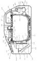
図1および図2は、本発明の第1実施形態に係る調理器である圧力炊飯器を示す。この圧力炊飯器は、電磁誘導加熱される調理鍋である炊飯鍋10を着脱可能に収容する炊飯器本体11と、該炊飯器本体11に回動可能に取り付けた蓋体24とからなる。
1 and 2 show a pressure rice cooker that is a cooker according to a first embodiment of the present invention. This pressure rice cooker includes a rice cooker body 11 that detachably accommodates a
前記炊飯器本体11は、筒形状をなす胴体12と、該胴体12の下端開口を閉塞する底体13と、胴体12の上端開口を覆うように取り付ける肩体14を有する外装体を備えている。肩体14には、その中央開口部の下側に筒状をなす内胴15と、非導電性材料からなる保護枠16とが配設されている。保護枠16の下部外周面には、炊飯鍋10の下部を誘導加熱する第1の加熱手段である誘導加熱コイル17がフェライトコア18を介して配設されている。また、保護枠16には、炊飯鍋10の温度を検出するための第1の温度検出手段である炊飯鍋用温度センサ19が配設されている。さらに、前記肩体14には、正面側に蓋体24のロック部34を係止するロック穴20が設けられている。さらにまた、肩体14の正面上側には、入力手段である複数のスイッチ21と、動作状況および操作状況を表示するための表示手段である液晶パネル22とを有する操作パネル23が配設されている。
The rice cooker main body 11 includes an exterior body having a cylindrical body 12, a bottom body 13 that closes a lower end opening of the body 12, and a shoulder body 14 that is attached to cover the upper end opening of the body 12. . The shoulder body 14 is provided with a cylindrical
前記蓋体24は、炊飯器本体11に開閉可能に取り付けられ、炊飯器本体11の開口部を閉塞するもので、炊飯器本体11の外装体と共に外表面材を構成する上板25と、該上板25の底を閉塞する下板26とを備えている。そして、下板26には、放熱板27と、第2の加熱手段である蓋ヒータ28と、炊飯鍋10の上端開口を閉塞する内蓋29とが配設されている。また、蓋体24の内部には、炊飯鍋10内の温度を検出する第2の温度検出手段である蓋体用温度センサ30が配設されている。
The
この蓋体24には、下板26の背部に肩体14に軸着されるヒンジ接続部31が設けられている。また、上板25の前部に該蓋体24を開放操作するための操作部材32が配設され、その背部(内部)にロック部材33が回動可能に取り付けられている。このロック部材33は、肩体14のロック穴20にロックするロック部34が下向きに突出するように設けられるとともに、前記操作部材32に押圧される突出部35が上向きに突出するように設けられ、図示しないスプリングによってロック方向に付勢されている。
The
そして、この蓋体24の内部には、炊飯鍋10内と外部とを連通する排気通路36が設けられ、この排気通路36に炊飯鍋10内を大気圧より高い圧力に昇圧するための密閉手段であるリリーフ弁37が配設されている。このリリーフ弁37は、炊飯制御時には炊飯鍋10内の圧力を調圧する役割をなすもので、円筒状をなす弁座部材38の上端開口に調圧ボール39が配設されたものである。この調圧ボール39は、例えば炊飯鍋10の内圧が1.25atmを超えると、炊飯鍋10内の蒸気により浮き上がり、炊飯鍋10内の蒸気を外部に排出するもので、マイコン55により動作される駆動手段であるソレノイド40の駆動により動作される。本実施形態では、ソレノイド40のロッド41を進出させることにより、調圧ボール39を押圧して開口上から後退させ、ロッド41を後退させることにより、自重で転動させて開口を閉鎖する構成としている。また、ロッド41には、後退させた加圧状態でロック部材33の突出部35の下部に進入して蓋体24の開放操作を阻止するリンク部材42が配設されている。なお、図中、符号43は、排気通路36を密閉した状態で、内部の調圧ボール39を動作させるためのパッキンである。
In addition, an
そして、本実施形態では、炊飯器本体11の背部に気体的変動による加圧手段である小型のダイヤフラムポンプ44が配設されている。このダイヤフラムポンプ44は、吸引部45と給気部46とを備えている。給気部46には、ヒンジ接続部31から蓋体24内に配管され、先端が炊飯鍋10内を臨むように配管された給気管47が接続されている。また、吸引部45には、図示しないエアフィルタが接続管を介して接続されている。
And in this embodiment, the
また、本実施形態では、炊飯器本体11の背部において、前記ダイヤフラムポンプ44の下部には、炊飯鍋10内に気体を混合した液体を供給する液体供給手段として、貯水槽48が設けられ、その下部に気化手段である加熱ヒータ49が配設されている。そして、貯水槽48の上部には供給管50は配置され、その先端が前記給気管47に分岐接続されている。なお、本実施形態では、胴体12において前記貯水槽48と対応する位置に給水口51が設けられ、この給水口51が開閉可能なカバー52により閉塞されている。なお、貯水槽48内の液体を気化する手段としては、加熱ヒータ49の代わりに超音波振動子を用いてもよい。
Moreover, in this embodiment, in the back part of the rice cooker main body 11, the water storage tank 48 is provided in the lower part of the said
前記構成の圧力炊飯器は、炊飯器本体11の正面側にホルダー53を介して配設した制御基板54に実装されたマイコン55によって、予め設定されたプログラムに従って炊飯制御および保温制御が実行される。なお、図中、符号56は制御基板54を冷却するためのファンである。
In the pressure rice cooker having the above configuration, rice cooking control and heat retention control are executed according to a preset program by the
この圧力炊飯器は、例えば、炊飯制御では、炊飯鍋10内を約50℃に維持する予熱工程を実行した後、ソレノイド40を動作させて炊飯鍋10内を密閉した状態で、炊飯鍋10内を沸騰させる昇温(中ぱっぱ)工程を実行する。そして、炊飯鍋10内が沸騰すると、水分が無くなる(ドライアップ)まで、リリーフ弁37で炊飯鍋10内を大気圧より高い所定圧力に調圧しながら沸騰状態を維持する沸騰維持(電力制御)工程を実行する。その後、蓋体用温度センサ30によってドライアップを検出すると、むらし工程を実行し、ソレノイド40を動作させて炊飯鍋10の内圧が大気圧と平衡するように開放して炊飯制御を終了する。また、炊飯制御が終了すると、続いて炊飯鍋10内を70℃に維持する保温制御を実行する。
For example, in the rice cooker control, this pressure rice cooker performs a preheating process for maintaining the inside of the
以上の炊飯制御および保温制御は従来と同様であるが、本実施形態では、誘導加熱コイル17の加熱によることなく炊飯鍋10内に強制的に圧力を付与することができるダイヤフラムポンプ44を搭載しているため、炊飯鍋10内の温度や残水量に拘わらず、炊飯鍋10内を強制的に昇圧することができる。即ち、希望時期に炊飯鍋10内に圧力を投入することができるため、炊飯に係る制御フローの自由度を大幅に向上でき、最適な炊飯を行うことが可能になる。
The above rice cooking control and heat retention control are the same as in the prior art, but in this embodiment, a
例えば、炊飯制御において、従来では加圧することができない低温の予熱工程にて、ソレノイド40を動作させて炊飯鍋10内を密閉した状態で、ダイヤフラムポンプ44を動作させることにより、炊飯鍋10内を大気圧より高い圧力に昇圧することができる。そして、ソレノイド40をオン、オフ制御して炊飯鍋10の内圧を加圧した状態と大気開放した状態とを繰り返すことにより、米に対する吸水を促進させることができる。
For example, in rice cooking control, by operating the
また、昇温工程(中ぱっぱ)では、炊飯鍋10内の水温が低温の場合に十分な加圧を行うことができなかったが、ダイヤフラムポンプ44を動作させることにより、炊飯鍋10内を大気圧より高い圧力に昇圧することができるため、米の細胞壁表面から内部のうま味成分を水中に溶出させることができ、その成分は、炊飯が進むにつれて全体の米の表面に再付着するため、炊き上げたご飯の食味(ねばりや甘み)を向上することができる。
Further, in the temperature raising step (medium chopping), sufficient pressurization could not be performed when the water temperature in the
また、沸騰維持(電力制御)工程では、ユーザによる炊飯鍋10内への給水量や米の含水量の違いにより、加圧時間や加圧値が増減する。そして、加圧時間が少ない場合にはダイヤフラムポンプ44を動作させることにより、設計通りの加圧時間を得ることができる。同様に、加圧値が変動する場合でも、ダイヤフラムポンプ44を動作させることにより一定の加圧値に維持できる。そのため、米のアルファ化を十分に促進させ、ユーザの水加減や米の含水量に伴う炊き上げ状態のバラツキを抑制できる。
Moreover, in a boiling maintenance (electric power control) process, pressurization time and a pressurization value increase / decrease with the difference in the amount of water supply to the
さらに、むらし工程では、炊飯鍋10内に水が残っていないため従来では維持しかできず、加圧することはできなかったが、ダイヤフラムポンプ44を動作させて加圧することにより、粘りのあるおいしいご飯を炊き上げることができる。
Furthermore, in the unevenness process, since water does not remain in the
さらにまた、従来では加圧できない保温制御では、ソレノイド40を動作させて炊飯鍋10内を密閉することにより、ご飯が含む水分の蒸散を抑制し、保湿を図ることができるとともに、保温電力を削減して省エネを図ることができる。しかも、ダイヤフラムポンプ44を動作させ、大気圧より高い圧力に昇圧することにより、炊飯鍋10内の空気が含むことが可能な飽和水蒸気量を増やすことができる。その結果、最適な保湿状態を確実に維持できる。
Furthermore, in the heat retention control that cannot be pressurized conventionally, the inside of the
しかも、本実施形態では、ダイヤフラムポンプ44に接続した給気管47に、気体を混合した液体である蒸気を供給する供給管50を分岐接続しているため、炊飯制御の実行中に加熱ヒータ49によって加熱を開始することにより、保温制御時に炊飯鍋10内に水蒸気を供給することもできる。そのため、しっとり感のある更に最適な保湿状態を維持できる。
In addition, in this embodiment, the
このように、本発明の圧力炊飯器では、炊飯鍋10内に空気を供給することにより該炊飯鍋10内を昇圧する構成としているため、迅速かつ細かな調圧が可能である。しかも、炊飯器本体11内の空気で昇圧する構成としているため、炊飯鍋10内の温度に影響は少ないうえ、炊飯鍋10内が低温であっても大気圧より高い圧力に昇圧することができる。
Thus, in the pressure rice cooker of this invention, since it is set as the structure which pressurizes the inside of this
因みに、液体供給手段として加熱ヒータ49の代わりに超音波振動子を適用した場合、供給する気液混同の流体温度は低いため、炊飯鍋10内の温度が低下することにより、炊飯鍋10の内圧が低下することになる。しかし、本実施形態では、加圧手段であるダイヤフラムポンプ44を動作させることにより、迅速に希望圧力に昇圧することができる。
Incidentally, when an ultrasonic vibrator is applied as the liquid supply means instead of the
図3は第2実施形態の圧力炊飯器を示す。この第2実施形態では、第1実施形態に示す供給管50をダイヤフラムポンプ44の吸引部45に接続することにより、空気の代わりに気液を混合した水蒸気により、炊飯鍋10内を昇圧させるようにした点で、第1実施形態と大きく相違している。なお、この場合には、液体の気化手段は、供給する流体温度を高めることができる点で、加熱ヒータ49を採用することが好ましい。言い換えれば、液体と一緒に空気を供給する第1実施形態に示す液体供給手段を、加圧手段として兼用している。
FIG. 3 shows a pressure rice cooker according to the second embodiment. In the second embodiment, by connecting the
この第2実施形態の圧力炊飯器でも、前記と同様に、密閉手段であるリリーフ弁37で排気通路36を閉塞した状態でダイヤフラムポンプ44を動作させることにより、炊飯鍋10内に気液を混合した高温の水蒸気を供給することにより、炊飯鍋10内を大気圧より高い圧力に昇圧することができるとともに、適量の水を供給することができる。
In the pressure rice cooker according to the second embodiment as well, the gas-liquid is mixed in the
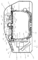
図4は第3実施形態の圧力炊飯器を示す。この第3実施形態では、蓋体24の内部に、炊飯鍋10内の圧力を検出する圧力検出手段として圧力センサ65を設け、この圧力センサ65の検出値に基づいてダイヤフラムポンプ44による加圧を調整する構成としている。また、この圧力センサ65において、炊飯鍋10内を臨ませる圧力センサパッキン66に対して、ダイヤフラムポンプ44の給気管47を分岐接続している。そして、この第3実施形態では、貯水槽48を有する液体供給手段は設けない構成とし、ダイヤフラムポンプ44を蓋体24内に配設している。さらに、第3実施形態では、ダイヤフラムポンプ44において、給気部(給気側)46に接続した給気管47に、炊飯鍋10からの逆流を防止する逆止弁67を介設している。
FIG. 4 shows a pressure rice cooker according to the third embodiment. In the third embodiment, a pressure sensor 65 is provided as pressure detection means for detecting the pressure in the
このように構成した第3実施形態では、第1実施形態と同様に、炊飯鍋10内の温度や残水量に拘わらず、炊飯鍋10内を強制的に昇圧することができるため、炊飯に係る制御フローの自由度を大幅に向上でき、最適な炊飯を行うことが可能になる。
In 3rd Embodiment comprised in this way, since the inside of the
次に、各実施形態の圧力炊飯器による炊飯制御について、具体的に説明する。 Next, the rice cooking control by the pressure rice cooker of each embodiment is demonstrated concretely.
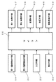
この炊飯制御では、マイコン55は、図5に示すように、まず、誘導加熱コイル17に通電を開始し、炊飯鍋10内の温度が約50℃を維持するように温度調節して加熱する予熱工程を実行する。この予熱工程は、誘導加熱コイル17と蓋ヒータ28の両方を動作させ、それぞれを独立してオン、オフ制御することにより行われる。本実施形態では、この予熱工程では、ソレノイド40を非動作状態とし、リリーフ弁37は、弁座部材38の開口を調圧ボール39によって閉塞させず、大気開放状態をなすようにしている。勿論、ダイヤフラムポンプ44も動作させていない。
In this rice cooking control, as shown in FIG. 5 , the
予め設定した時間が経過することにより予熱工程が終了すると、炊飯鍋10内の米を含む水を沸騰させる昇温(中ぱっぱ)工程を実行する。この昇温工程は、米の吸水を調整するために、開始当初は、誘導加熱コイル17に対して100%(フルパワー)の電力で通電し、所定時間後に予め設定した通電量に低下させる。その後、その通電量を略維持するように誘導加熱コイル17をオン、オフ制御することにより行われる。本実施形態では、この昇温工程では、ソレノイド40を動作させ、リリーフ弁37は、弁座部材38の開口を調圧ボール39によって閉塞し、炊飯鍋10内を加圧可能な状態とする。また、ダイヤフラムポンプ44を動作させ、炊飯鍋10内を約1.15atmに調圧する。なお、この昇温工程では、加熱中のご飯の温度の上昇勾配により、炊飯鍋10内に収容された炊飯容量を判別する容量判別工程を並行処理する。
When the preheating process is finished by elapse of a preset time, a temperature raising (medium-patch) process for boiling water containing rice in the
昇温工程により炊飯鍋10内が、予め設定した温度(蓋体用温度センサ30による検出値60℃)に達すると、沸騰状態を維持するように電力を調整する沸騰維持(電力制御)工程を実行する。この沸騰維持工程は、誘導加熱コイル17と蓋ヒータ28の両方を動作させ、それぞれを独立してオン、オフ制御することにより行われる。本実施形態の沸騰維持工程は、炊飯鍋10内を大気開放して大気圧と平衡させた状態で均し段階(第1ステップ)と、炊飯鍋10内を大気圧より高い圧力に昇圧させた状態で行う加圧段階(第2ステップ)とからなる構成としている。
When the inside of the
均し段階は、まず、ダイヤフラムポンプ44の動作を停止する。また、ソレノイド40の動作を停止することにより、リリーフ弁37は、調圧ボール39を後退させて、弁座部材38の開口を開放する。さらに、誘導加熱コイル17に対する通電量を低下させることにより、蒸気の発生を抑制し、炊飯鍋10の内圧を迅速に大気圧と平衡させる。なお、この均し段階の実行時間は、昇温工程で判断した炊飯容量、および、ユーザが設定した炊飯メニューに基づいて、30秒から3分の間で予め設定されている。即ち、炊飯メニューおよび炊飯容量が異なると、昇温工程時の余熱で吹きこぼれが生じる可能性も変わる。そのため、吹きこぼれが生じる可能性が高い条件のものは実行時間を長く設定し、可能性が低い条件のものは実行時間を短く設定している。
In the leveling step, first, the operation of the
加圧段階は、再びソレノイド40を動作させ、調圧ボール39によって炊飯鍋10内を加圧可能な状態とする。但し、この沸騰維持工程の加圧段階では、ダイヤフラムポンプ44を動作させることなく、誘導加熱コイル17による加熱、それに伴って炊飯鍋10内で加熱された水の蒸気により、該炊飯鍋10内を昇圧させる。また、誘導加熱コイル17に対する通電量を増大させる。なお、誘導加熱コイル17に対する通電は、昇温工程で判断した炊飯量に基づいて予め設定した温度に達すると通電量を低下させる。その後、炊飯鍋10内の残水量が少なくなり、誘導加熱コイル17に対する通電量を高め、米を炊き上げる(炊き上げ工程)。
In the pressurization stage, the
沸騰維持工程により炊飯鍋10内のドライアップを検出すると、炊飯鍋10内の余分な水分を放出させる第1むらし工程を実行する。この第1むらし工程は、誘導加熱コイル17は動作させることなく、蓋ヒータ28をオン、オフ制御することにより行われる。そして、本実施形態の第1むらし工程は、炊飯鍋10内を大気開放した状態で行うむらし1(第1ステップ)と、内圧を大気圧より高い圧力に加圧した状態で行うむらし2(第2ステップ)とからなる構成としている。
When dry-up in the
むらし1は、判別した炊飯容量に基づいて予め設定された時間行われる。本実施形態では、ソレノイド40を非動作状態とし、調圧ボール39によって大気開放状態をなすようにし、ダイヤフラムポンプ44も動作させずに行う。
The
むらし2は、同様に判別した炊飯容量に基づいて予め設定された時間行われる。本実施形態では、ソレノイド40を動作させ、調圧ボール39によって炊飯鍋10内を加圧可能な状態とし、ダイヤフラムポンプ44を動作させ、炊飯鍋10内を約1.15atmに調圧するように行う。
The
第1むらし工程が終了すると、米に含まれた余分な水分を放出および蒸発させるために、2度炊き(再加熱)工程を実行する。この2度炊き工程は、判別した炊飯容量に基づいた時間、かつ、設定された炊き上げ状態の硬さに基づいて予め設定された通電量で、誘導加熱コイル17および蓋ヒータ28をオン、オフ制御することにより行われる。そして、本実施形態では、ソレノイド40を非動作状態とし、調圧ボール39によって大気開放状態をなすようにし、ダイヤフラムポンプ44も動作させずに行う。
When the first unevenness process is completed, a twice-cooking (reheating) process is performed to release and evaporate excess moisture contained in the rice. This twice-cooking process turns the
2度炊き工程が終了すると、内蓋29に付着した水分を蒸発させるとともに、米に対して粘りを付与するために第2むらし工程(むらし3)を実行する。この第2むらし工程は、誘導加熱コイル17は動作させることなく、蓋ヒータ28をフルパワーで動作させることにより行われる。本実施形態では、ソレノイド40を動作させ、調圧ボール39によって炊飯鍋10内を加圧可能な状態とし、ダイヤフラムポンプ44を動作させ、炊飯鍋10内を約1.15atmに調圧するように行う。
When the twice-cooking process is completed, the water adhering to the
第2むらし工程を予め設定された時間実行すると、ソレノイド40を非動作状態とし、調圧ボール39によって大気開放状態をなすようにし、ダイヤフラムポンプ44も非動作状態として、保温制御に移行する。
When the second unevenness process is executed for a preset time, the
このように、本発明の炊飯制御では、加圧手段としてダイヤフラムポンプ44を設けているため、誘導加熱コイル17の加熱に伴う温度および蒸気の発生量に頼ることなく、強制的に炊飯鍋10の内圧を高めることができる。その結果、従来では大気圧より高い圧力に昇圧させることができない昇温工程やむらし工程で、炊飯鍋10の内圧を大気圧より高い圧力に高めることができる。
Thus, in the rice cooking control of the present invention, since the
そして、昇温工程で大気圧より高い圧力に昇圧することにより、調理物である米に対して短時間で内部まで熱を加えることができる。また、米のアルファ化を促進させ、炊き上げたご飯の食味(ねばりや甘み)を向上することができる。さらに、リリーフ弁37およびダイヤフラムポンプ44により、炊飯鍋10内を昇圧しているため、大気開放状態の場合と比較すると、同一の通電量で高い加熱量を得ることができる。その結果、省エネを図ることができる。
And by raising the pressure to a pressure higher than the atmospheric pressure in the temperature raising step, heat can be applied to the inside of the cooked rice in a short time. Moreover, the alpha conversion of rice can be promoted and the taste (stickiness and sweetness) of the cooked rice can be improved. Furthermore, since the inside of the
また、昇温工程の次に実行する沸騰維持工程では、まず、リリーフ弁37によって炊飯鍋10内を大気開放して大気圧と平衡させた状態で均し段階を実行し、炊飯鍋10内を大気圧と平衡させる。そのため、沸騰維持工程に移行した直後に、炊飯鍋10内で発生した蒸気により、リリーフ弁37が急激な昇圧に対応できず、限度圧力を超える危険性を回避できる。そして、その後の昇圧段階では、従来と同様に誘導加熱コイル17による加熱で炊飯鍋10内を大気圧より高い圧力に昇圧するため、安定した調圧制御を行うことができる。
Moreover, in the boiling maintenance process performed after a temperature rising process, first, the leveling step is performed in a state where the inside of the
さらに、第1むらし工程では、第1ステップにて炊飯鍋10内の余分な蒸気を放出させた状態で、第2ステップにて大気圧より高い圧力に昇圧させる。そのため、調理物である米に対して味を浸透させることができるうえ、アルファ化を促進させ、ねばりや甘みを増大させることができる。また、省エネを図ることができる。
Further, in the first unevenness process, the pressure is raised to a pressure higher than the atmospheric pressure in the second step in a state where excess steam in the
そして、第1むらし工程の後に、炊飯鍋10を大気開放した状態で加熱を行う2度炊き工程を更に設けているため、米が含んだ余分な水分を確実に放出させることができる。これにより、ユーザが設定した希望通りの硬さを実現できる。一方、この2度炊き工程では、誘導加熱コイル17を動作させて高い加熱量を付与するものである。そのため、この2度炊き工程を密閉した昇圧状態で行うと、炊飯鍋10の内部は過剰加熱になるため、ご飯に焦げが生じる可能性がある。しかし、本実施形態では、炊飯鍋10内を大気開放した状態で行うため、過剰加熱を防止し、焦げが生じることを防止できる。
And since the 2nd cooking process which heats in the state which open | released the
しかも、本実施形態では、米の硬さを調整する2度炊き工程の後に、更に第2むらし工程を設け、この第2むらし工程では、リリーフ弁37およびダイヤフラムポンプ44により、炊飯鍋10内を強制的に大気圧より高い圧力に昇圧させる。そのため、調理物である米に対して味を更に浸透させることができるうえ、ねばりや甘みを増大させることができる。また、省エネを図ることができる。
Moreover, in the present embodiment, after the twice-cooking process for adjusting the hardness of the rice, a second unevenness process is further provided. In the second unevenness process, the relief valve 37 and the
次に、炊飯制御が終了した後に引き続いて実行される保温制御について説明する。 Next, the heat retention control that is subsequently executed after the rice cooking control is completed will be described.
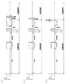
図6(A)に示すように、まず、保温制御に移行すると、10秒後にダイヤフラムポンプ44を6秒間動作させる。即ち、炊飯制御が終了し、ダイヤフラムポンプ44を停止するとともに、炊飯鍋10内を大気開放した状態で、予め設定した待機時間(10秒)が経過した後にダイヤフラムポンプ44を動作(保守駆動)させる。これにより、炊飯制御時に発生した蒸気やオネバ等がダイヤフラムポンプ44に逆流して侵入し、該ダイヤフラムポンプ44を故障させることを防止できる。
As shown in FIG. 6 (A), first, when shifting to the heat retention control, the
なお、本実施形態では、炊飯制御の終了直前の工程(むらし3)でダイヤフラムポンプ44によって炊飯鍋10内を強制的に昇圧したため、炊飯制御が終了した直後に、所定の待機時間経過するとダイヤフラムポンプ44を保守駆動させたが、図6(B)に示すように、炊飯制御が終了する直前の工程で、炊飯鍋10内を昇圧させない場合、炊飯制御が終了した直後に、待機時間を設けることなくダイヤフラムポンプ44を保守駆動させてもよい。または、図6(C)に示すように、炊飯制御の終了直前にダイヤフラムポンプ44を保守駆動させてもよい。勿論、炊飯制御の終了の所定時間前にダイヤフラムポンプ44を保守駆動させてもよい。
In addition, in this embodiment, since the inside of the
即ち、炊飯(調理)制御において、ダイヤフラムポンプ44によって炊飯鍋10内を昇圧させる工程は、炊飯(調理)メニューに応じて変更される。そのため、終了直前の工程でダイヤフラムポンプ44を動作させている場合には、炊飯制御が終了した直後に所定の待機時間経過後にダイヤフラムポンプ44を動作させ、終了直前の工程でダイヤフラムポンプ44を動作させていない場合には、炊飯制御の終了前後にダイヤフラムポンプ44を保守駆動させることができる。
That is, in the rice cooking (cooking) control, the step of increasing the pressure in the
次に、保温制御での温調について説明する。なお、本実施形態の保温制御は図7(A)に示す通りであり、従来の保温制御は図7(B)に示す通りである。そして、以下の説明では、本実施形態と従来の保温制御を比較しながら説明する。 Next, temperature control in the heat retention control will be described. In addition, the heat retention control of this embodiment is as shown to FIG. 7 (A), and the conventional heat retention control is as shown to FIG. 7 (B). In the following description, the present embodiment will be described while comparing conventional heat retention control.
また、保温制御では、まず、第1ステップとして保温温度を60℃に維持する第1低温保温工程を実行する。ここで、保温制御に移行した直後は、炊飯鍋10内の温度は約100℃である。そのため、この第1ステップでは、誘導加熱コイル17の動作は停止される。そして、炊飯鍋10内の温度が60℃まで降温すると、その温度を維持するように誘導加熱コイル17をオン、オフ制御する。なお、この第1ステップは、本実施形態では8時間実行され、従来では6時間実行される。
In the heat retention control, first, as a first step, a first low temperature heat retaining step for maintaining the heat retaining temperature at 60 ° C. is executed. Here, immediately after shifting to heat retention control, the temperature in the
時間の経過により低温保温による第1ステップが終了すると、第2ステップとして、保温温度が70℃になるように昇温させる第1昇温工程を実行する。なお、この第2ステップは、本実施形態および従来のいずれも2時間かけて70℃まで昇温するように、誘導加熱コイル17をオン、オフ制御する。
When the first step due to the low temperature insulation is completed with the passage of time, a first temperature raising step for raising the temperature so that the temperature keeping is 70 ° C. is executed as the second step. In the second step, the
第2ステップが終了すると、第3ステップとして保温温度を70℃に維持する第1高温保温工程を実行する。なお、第3ステップは、本実施形態および従来のいずれも4時間実行され、誘導加熱コイル17は70℃を維持するようにオン、オフ制御される。
When the second step is completed, a first high temperature heat retaining process for maintaining the heat retaining temperature at 70 ° C. is performed as a third step. Note that the third step is executed for 4 hours in both the present embodiment and the conventional method, and the
第3ステップが終了すると、第4ステップとして保温温度を60℃に維持する第2低温保温工程を実行する。この第4ステップでは、誘導加熱コイル17の動作は停止される。そして、炊飯鍋10内の温度が60℃まで降温すると、その温度を維持するように誘導加熱コイル17をオン、オフ制御する。なお、この第4ステップは、本実施形態では4時間実行され、従来では6時間実行される。
When the third step is completed, a second low temperature heat retaining step for maintaining the heat retaining temperature at 60 ° C. is performed as a fourth step. In the fourth step, the operation of the
第4ステップが終了すると、第5ステップとして、保温温度が70℃になるように昇温させる第2昇温工程を実行する。なお、この第5ステップは、本実施形態および従来のいずれも2時間かけて70℃まで昇温するように、誘導加熱コイル17をオン、オフ制御する。
When the fourth step is finished, as a fifth step, a second temperature raising step for raising the temperature so that the heat retention temperature becomes 70 ° C. is executed. In this fifth step, the
第5ステップが終了すると、第6ステップとして保温温度を70℃に維持する第2高温保温工程を実行する。なお、第6ステップは、本実施形態および従来のいずれもとりけしスイッチの操作により保温制御が停止されるまで実行され、誘導加熱コイル17は70℃を維持するようにオン、オフ制御される。
When the fifth step is completed, a second high temperature heat retaining step for maintaining the heat retaining temperature at 70 ° C. is performed as a sixth step. Note that the sixth step is executed until the heat insulation control is stopped by the operation of both the present embodiment and the conventional switch, and the
即ち、本実施形態と従来では、第1ステップから第6ステップまでの24時間を比べると消費電力は同一であるが、第2低温保温工程の時間を第1低温保温工程に割り当てた状態で制御を行うようにしている。そして、ユーザの使用習慣としては、炊き上げた米は24時間以上保温することは極めて少なく、保温開始から12時間以内に保温制御を停止させることが多い。よって、その実際の使用時間内では、低温保温時間が長くなっている。そのため、その分、省エネを図ることができるうえ、保温状態も向上することができる。 That is, in the present embodiment and the prior art, the power consumption is the same when comparing the 24 hours from the first step to the sixth step, but the control is performed in the state where the time of the second low temperature heat insulation process is assigned to the first low temperature heat insulation process. Like to do. And as a user's usage habits, the cooked rice is rarely kept warm for more than 24 hours, and often the heat keeping control is stopped within 12 hours from the start of keeping warm. Therefore, the low temperature heat retention time is longer within the actual use time. Therefore, it is possible to save energy and to improve the heat insulation state.
また、本実施形態では、ダイヤフラムポンプ44の給気側である給気部46に接続した給気管47を圧力センサパッキン66に分岐接続し、給気管47に逆止弁67を介設しているため、ダイヤフラムポンプ44に炊飯鍋10内で発生した蒸気やオネバが逆流することによる故障を防止できる。しかも、本実施形態では、炊飯制御が終了すると、ダイヤフラムポンプ44を所定時間動作させるため、給気管47内に侵入しているオネバや、蒸気が結露した水などを、炊飯鍋10に戻すことができる。その結果、ダイヤフラムポンプ44の故障を確実に防止できる。
In the present embodiment, the
図8はマイコンによる炊飯制御の変形例を示す。この変形例は、従来では昇圧できなかった予熱工程で、炊飯鍋10の内圧を大気圧より高い圧力に昇圧した状態と、平衡させた状態を交互に行うようにした点で、大きく相違している。また、ダイヤフラムポンプ44は、その動作停止状態が所定時間以上継続すると、所定時間動作させるようにした点で相違している。
FIG. 8 shows a modification of rice cooking control by a microcomputer. This modification is greatly different in that the state in which the internal pressure of the
具体的には、マイコン55は、予熱工程では、誘導加熱コイル17に通電を開始し、炊飯鍋10内の温度が約50℃を維持するように、誘導加熱コイル17と蓋ヒータ28の両方を動作させ、それぞれを独立してオン、オフ制御する。そして、この加熱制御と並行して、リリーフ弁37およびダイヤフラムポンプ44を制御し、大気開放状態と、密閉昇圧状態とを交互に繰り返すように制御する。
Specifically, in the preheating step, the
即ち、予熱工程を開始して60秒が経過すると、ソレノイド40を動作させ、調圧ボール39によって炊飯鍋10内を加圧可能な状態とし、ダイヤフラムポンプ44を動作させ、炊飯鍋10内を約1.15atmに調圧する。そして、この調圧状態が30秒経過すると、ソレノイド40を非動作状態とし、調圧ボール39によって大気開放状態をなすようにし、ダイヤフラムポンプ44も動作を停止する。そして、この停止(大気開放)状態が30秒経過すると、再び調圧状態とし、これらを予熱工程が完了するまで繰り返す。但し、予熱工程の終了時には、ソレノイド40を非動作状態とし、調圧ボール39によって大気開放状態をなすようにし、ダイヤフラムポンプ44も動作を停止した状態とする。
That is, when 60 seconds elapses after the preheating process is started, the
予熱工程が終了すると、前記と同様に、昇圧工程、沸騰維持工程、第1むらし工程、2度炊き工程、第2むらし工程を実行して保温制御に移行する。 When the preheating step is completed, the pressure raising step, the boiling maintaining step, the first unevenness step, the twice cooking step, and the second unevenness step are executed and the process proceeds to the heat retention control.
但し、沸騰維持工程では、リリーフ弁37によって炊飯鍋10内を密閉しているが、ダイヤフラムポンプ44は停止状態が維持される。そのため、この停止状態が300秒以上継続すると、5秒間、ダイヤフラムポンプを動作させる。また、保温制御に移行すると、前記実施形態では、ダイヤフラムポンプ44が停止状態を維持する。そのため、この保温制御においても、停止状態が300秒以上継続すると、5秒間、ダイヤフラムポンプを動作させる。これにより、ダイヤフラムポンプ44が蒸気やオネバ逆流により故障することを防止できるようにしている。
However, in the boiling maintenance step, the inside of the
このように、この炊飯制御では、予熱工程でも炊飯鍋10内を昇圧する構成としている。しかも、昇圧状態と大気開放状態とを所定時間毎に繰り返すように構成している。そのため、調理物である米に対する吸水を促進させることができる。
Thus, in this rice cooking control, it is set as the structure which pressurizes the inside of the
なお、本発明の調理器は、前記実施形態の構成に限定されるものではなく、種々の変更が可能である。 In addition, the cooking device of this invention is not limited to the structure of the said embodiment, A various change is possible.
例えば、第2実施形態では、内壁部57を進退させるための駆動手段としてダイヤフラムポンプ44を適用したが、進退可能な機構であればいずれでも適用可能であり、同様の作用および効果を得ることができる。
For example, in the second embodiment, the
また、前記各実施形態では、リリーフ弁37のみを適用した圧力炊飯器で説明したが、ステッピングモータにより通気孔に弁体を付勢する力を可変することにより、多段階の圧力調整が可能な調圧弁を適用した圧力炊飯器でも同様に適用可能である。この場合、リリーフ弁37によって大気開放するのではなく、調圧弁によって段階的に減圧することが可能になる。その結果、炊飯鍋10内の圧力(蒸気)が一気に蒸気口から噴出することを防止できるため、安全性を確保できる。
In each of the above embodiments, the pressure rice cooker to which only the relief valve 37 is applied has been described. However, by changing the force for urging the valve body to the vent hole by the stepping motor, multi-stage pressure adjustment is possible. The same can be applied to a pressure rice cooker to which a pressure regulating valve is applied. In this case, the pressure can be reduced stepwise by the pressure regulating valve instead of opening to the atmosphere by the relief valve 37. As a result, it is possible to prevent the pressure (steam) in the
さらに、前記実施形態では、加熱手段として誘導加熱コイル17と蓋ヒータ28とを搭載したが、誘導加熱コイル17の上部に位置する内胴の外周部に更に加熱手段として胴ヒータを配設したものでも、同様に適用可能である。
Further, in the above embodiment, the
勿論、本発明の強制加圧機構を搭載可能な機器は圧力炊飯器に限られず、所定の調理材料を調理する調理器にも同様に適用可能であり、同様の作用および効果を得ることができる。 Of course, the apparatus which can mount the forced pressurization mechanism of this invention is not restricted to a pressure rice cooker, It can apply similarly to the cooker which cooks a predetermined cooking material, and can acquire the same effect | action and effect. .
10…炊飯鍋(調理鍋)
11…炊飯器本体(調理器本体)
17…誘導加熱コイル(加熱手段)
19…炊飯鍋用温度センサ(温度検出手段)
24…蓋体
28…蓋ヒータ(加熱手段)
30…蓋体用温度センサ(温度検出手段)
36…排気通路
37…リリーフ弁(密閉手段)
40…ソレノイド(駆動手段)
44…ダイヤフラムポンプ(加圧手段、液体供給手段)
48…貯水槽(液体供給手段)
55…マイコン(制御手段)
10 ... Cooking pot (cooking pot)
11 ... Rice cooker body (cooker body)
17 ... induction heating coil (heating means)
19 ... Rice cooker temperature sensor (temperature detection means)
24 ...
30 ... Temperature sensor for lid (temperature detection means)
36 ... Exhaust passage 37 ... Relief valve (sealing means)
40 ... Solenoid (driving means)
44 ... Diaphragm pump (pressurizing means, liquid supply means)
48 ... Water tank (liquid supply means)
55. Microcomputer (control means )
Claims (11)
前記調理器本体内に設けられ、前記調理鍋を加熱する加熱手段と、
前記調理器本体に開閉可能に取り付けられ、前記調理鍋を閉塞する蓋体と、
前記蓋体内に設けられ、前記調理鍋内と外部とを連通する排気通路と、
前記蓋体内に設けられ、前記排気通路を閉塞して前記調理鍋内を加圧可能とするとともに、前記排気通路を開放して前記調理鍋内の圧力を大気圧と平衡させる密閉手段と、
前記調理鍋内または調理鍋の温度を検出する温度検出手段と、
前記密閉手段で調理鍋内を閉塞した状態で、該調理鍋内に気体を供給することにより前記加熱手段の加熱によることなく大気圧より高い圧力を付与する加圧手段と、
前記温度検出手段による検出値に基づいて、前記加熱手段、密閉手段および加圧手段を制御して、予熱、昇温、沸騰維持、および、むらしの工程を順次実行して調理制御を行う制御手段と、
を備え、
前記制御手段による前記むらし工程は、前記密閉手段によって前記調理鍋内を大気開放した状態で行う第1ステップと、前記密閉手段によって前記調理鍋を加圧可能とし前記加圧手段によって大気圧より高い圧力に加圧した状態で行う第2ステップとを備えることを特徴とする調理器。 A cooker body containing a cooking pot;
A heating means provided in the cooker body for heating the cooking pan;
A lid that is attached to the cooker body so as to be openable and closable, and closes the cooking pan;
An exhaust passage which is provided in the lid and communicates between the inside of the cooking pan and the outside;
A sealing means provided in the lid, capable of pressurizing the cooking pan by closing the exhaust passage, and opening the exhaust passage to balance the pressure in the cooking pan with atmospheric pressure;
Temperature detecting means for detecting the temperature of the cooking pot or the cooking pot;
In a state where the cooking pot is closed with the sealing means, a pressurizing means for applying a pressure higher than the atmospheric pressure by supplying gas into the cooking pot without heating the heating means,
Control for controlling cooking by controlling the heating means, the sealing means and the pressurizing means based on the detection value by the temperature detecting means , and sequentially executing the preheating, temperature rising, boiling maintenance and unevenness steps. Means,
Equipped with a,
The unevenness process by the control means includes a first step performed in a state in which the cooking pot is opened to the atmosphere by the sealing means, and the cooking pot can be pressurized by the sealing means, and the atmospheric pressure is increased by the pressurizing means. A cooking device comprising: a second step performed in a state of being pressurized to a high pressure .
前記調理器本体内に設けられ、前記調理鍋を加熱する加熱手段と、
前記調理器本体に開閉可能に取り付けられ、前記調理鍋を閉塞する蓋体と、
前記蓋体内に設けられ、前記調理鍋内と外部とを連通する排気通路と、
前記蓋体内に設けられ、前記排気通路を閉塞して前記調理鍋内を加圧可能とするとともに、前記排気通路を開放して前記調理鍋内の圧力を大気圧と平衡させる密閉手段と、
前記調理鍋内または調理鍋の温度を検出する温度検出手段と、
前記密閉手段で調理鍋内を閉塞した状態で、該調理鍋内に気体を供給することにより前記加熱手段の加熱によることなく大気圧より高い圧力を付与する加圧手段と、
前記温度検出手段による検出値に基づいて、前記加熱手段、密閉手段および加圧手段を制御して、予熱、昇温、沸騰維持、および、むらしの工程を順次実行して調理制御を行う制御手段と、
を備え、
前記制御手段による前記むらし工程の後に、前記密閉手段によって前記調理鍋内を大気開放した状態で前記加熱手段によって加熱を行う2度炊き工程を設けるとともに、該2度炊き工程の後に、前記密閉手段によって前記調理鍋を加圧可能とし前記加圧手段によって大気圧より高い圧力に加圧した状態で行う第2むらし工程を更に設けたことを特徴とする調理器。 A cooker body containing a cooking pot;
A heating means provided in the cooker body for heating the cooking pan;
A lid that is attached to the cooker body so as to be openable and closable, and closes the cooking pan;
An exhaust passage which is provided in the lid and communicates between the inside of the cooking pan and the outside;
A sealing means provided in the lid, capable of pressurizing the cooking pan by closing the exhaust passage, and opening the exhaust passage to balance the pressure in the cooking pan with atmospheric pressure;
Temperature detecting means for detecting the temperature of the cooking pot or the cooking pot;
In a state where the cooking pot is closed with the sealing means, a pressurizing means for applying a pressure higher than the atmospheric pressure by supplying gas into the cooking pot without heating the heating means,
Control for controlling cooking by controlling the heating means, the sealing means and the pressurizing means based on the detection value by the temperature detecting means , and sequentially executing the preheating, temperature rising, boiling maintenance and unevenness steps. Means,
Equipped with a,
After the unevenness process by the control means, a two-time cooking process is performed in which the cooking means is heated by the heating means in a state where the cooking pot is opened to the atmosphere by the sealing means, and the sealing is performed after the two-time cooking process. A cooking device, further comprising a second unevenness step, wherein the cooking pan can be pressurized by means and is pressurized to a pressure higher than atmospheric pressure by the pressure means .
Priority Applications (1)
| Application Number | Priority Date | Filing Date | Title |
|---|---|---|---|
| JP2007114177A JP4823963B2 (en) | 2006-09-13 | 2007-04-24 | Cooking device |
Applications Claiming Priority (3)
| Application Number | Priority Date | Filing Date | Title |
|---|---|---|---|
| JP2006248079 | 2006-09-13 | ||
| JP2006248079 | 2006-09-13 | ||
| JP2007114177A JP4823963B2 (en) | 2006-09-13 | 2007-04-24 | Cooking device |
Publications (3)
| Publication Number | Publication Date |
|---|---|
| JP2008093409A JP2008093409A (en) | 2008-04-24 |
| JP2008093409A5 JP2008093409A5 (en) | 2009-07-16 |
| JP4823963B2 true JP4823963B2 (en) | 2011-11-24 |
Family
ID=39376873
Family Applications (1)
| Application Number | Title | Priority Date | Filing Date |
|---|---|---|---|
| JP2007114177A Expired - Fee Related JP4823963B2 (en) | 2006-09-13 | 2007-04-24 | Cooking device |
Country Status (1)
| Country | Link |
|---|---|
| JP (1) | JP4823963B2 (en) |
Families Citing this family (9)
| Publication number | Priority date | Publication date | Assignee | Title |
|---|---|---|---|---|
| JP5124156B2 (en) * | 2007-04-09 | 2013-01-23 | 三洋電機株式会社 | Pressure cooker |
| JP5380669B2 (en) * | 2009-05-26 | 2014-01-08 | 象印マホービン株式会社 | Container with lid |
| JP5735398B2 (en) * | 2011-11-07 | 2015-06-17 | 象印マホービン株式会社 | Pressure cooker |
| JP5745553B2 (en) * | 2013-01-29 | 2015-07-08 | 三菱電機株式会社 | rice cooker |
| KR101597548B1 (en) * | 2014-08-29 | 2016-02-25 | 쿠쿠전자 주식회사 | Electric cooker |
| CN109124344B (en) * | 2017-06-19 | 2024-03-22 | 佛山市顺德区美的电热电器制造有限公司 | Cooking apparatus |
| JP7117596B2 (en) * | 2018-03-02 | 2022-08-15 | パナソニックIpマネジメント株式会社 | rice cooker |
| CN208988479U (en) * | 2017-07-28 | 2019-06-18 | 浙江绍兴苏泊尔生活电器有限公司 | Cooking utensil |
| CN214072902U (en) | 2020-11-23 | 2021-08-31 | 佛山市顺德区美的电热电器制造有限公司 | Pot body subassembly and cooking utensil |
Family Cites Families (4)
| Publication number | Priority date | Publication date | Assignee | Title |
|---|---|---|---|---|
| JPH07100057A (en) * | 1993-10-07 | 1995-04-18 | Matsushita Electric Ind Co Ltd | Rice cooker |
| JP3242569B2 (en) * | 1996-04-25 | 2001-12-25 | 象印マホービン株式会社 | Heating vessel |
| JPH1080357A (en) * | 1996-09-10 | 1998-03-31 | Kishimoto Akira | Rice cooking receptacle for microwave oven |
| JP3670973B2 (en) * | 2001-02-16 | 2005-07-13 | 象印マホービン株式会社 | rice cooker |
-
2007
- 2007-04-24 JP JP2007114177A patent/JP4823963B2/en not_active Expired - Fee Related
Also Published As
| Publication number | Publication date |
|---|---|
| JP2008093409A (en) | 2008-04-24 |
Similar Documents
| Publication | Publication Date | Title |
|---|---|---|
| JP4823963B2 (en) | Cooking device | |
| RU2468730C2 (en) | Method and device for cooking food, such as rice | |
| JP3417916B2 (en) | Steam discharge device of electric pressure cooker | |
| JP4873429B2 (en) | Pressure cooker | |
| JP2008048766A (en) | Pressure rice cooker and pressure rice cooking method | |
| EP1761111A2 (en) | Steam generation system for a household oven | |
| JP2011078533A (en) | Pressure rice cooker | |
| JP2007236730A (en) | Rice cooker | |
| JP4823831B2 (en) | Rice cooker control method and rice cooker | |
| JP4663347B2 (en) | Pressure cooker | |
| JP3851293B2 (en) | Pressure rice cooker and pressure rice cooking method | |
| JP4602938B2 (en) | Pressure cooker | |
| JP2011010974A (en) | Electric rice cooker | |
| JP4595239B2 (en) | Electric pressure cooker | |
| JP2011087615A (en) | Rice cooker | |
| JP3420962B2 (en) | Pressure cooker | |
| JP3349665B2 (en) | Pressure cooker | |
| JP2007321993A (en) | Heating cooker | |
| JP5124156B2 (en) | Pressure cooker | |
| JP2017035322A (en) | rice cooker | |
| JP6825993B2 (en) | Cooker | |
| JP6814100B2 (en) | Cooker | |
| JP4186821B2 (en) | rice cooker | |
| JP4036208B2 (en) | rice cooker | |
| JP4208137B2 (en) | rice cooker |
Legal Events
| Date | Code | Title | Description |
|---|---|---|---|
| A521 | Request for written amendment filed |
Free format text: JAPANESE INTERMEDIATE CODE: A523 Effective date: 20090529 |
|
| A621 | Written request for application examination |
Free format text: JAPANESE INTERMEDIATE CODE: A621 Effective date: 20090529 |
|
| A131 | Notification of reasons for refusal |
Free format text: JAPANESE INTERMEDIATE CODE: A131 Effective date: 20110621 |
|
| A521 | Request for written amendment filed |
Free format text: JAPANESE INTERMEDIATE CODE: A523 Effective date: 20110802 |
|
| TRDD | Decision of grant or rejection written | ||
| A01 | Written decision to grant a patent or to grant a registration (utility model) |
Free format text: JAPANESE INTERMEDIATE CODE: A01 Effective date: 20110906 |
|
| A01 | Written decision to grant a patent or to grant a registration (utility model) |
Free format text: JAPANESE INTERMEDIATE CODE: A01 |
|
| A61 | First payment of annual fees (during grant procedure) |
Free format text: JAPANESE INTERMEDIATE CODE: A61 Effective date: 20110907 |
|
| R150 | Certificate of patent or registration of utility model |
Ref document number: 4823963 Country of ref document: JP Free format text: JAPANESE INTERMEDIATE CODE: R150 Free format text: JAPANESE INTERMEDIATE CODE: R150 |
|
| FPAY | Renewal fee payment (event date is renewal date of database) |
Free format text: PAYMENT UNTIL: 20140916 Year of fee payment: 3 |
|
| R250 | Receipt of annual fees |
Free format text: JAPANESE INTERMEDIATE CODE: R250 |
|
| R250 | Receipt of annual fees |
Free format text: JAPANESE INTERMEDIATE CODE: R250 |
|
| R250 | Receipt of annual fees |
Free format text: JAPANESE INTERMEDIATE CODE: R250 |
|
| LAPS | Cancellation because of no payment of annual fees |