JP4820249B2 - Auxiliary step device for getting on and off the vehicle - Google Patents
Auxiliary step device for getting on and off the vehicle Download PDFInfo
- Publication number
- JP4820249B2 JP4820249B2 JP2006251865A JP2006251865A JP4820249B2 JP 4820249 B2 JP4820249 B2 JP 4820249B2 JP 2006251865 A JP2006251865 A JP 2006251865A JP 2006251865 A JP2006251865 A JP 2006251865A JP 4820249 B2 JP4820249 B2 JP 4820249B2
- Authority
- JP
- Japan
- Prior art keywords
- base
- shaft
- auxiliary step
- support
- shaped
- Prior art date
- Legal status (The legal status is an assumption and is not a legal conclusion. Google has not performed a legal analysis and makes no representation as to the accuracy of the status listed.)
- Expired - Fee Related
Links
- 230000035939 shock Effects 0.000 claims description 3
- 238000005452 bending Methods 0.000 claims description 2
- ULEBESPCVWBNIF-BYPYZUCNSA-N L-arginine amide Chemical compound NC(=O)[C@@H](N)CCCNC(N)=N ULEBESPCVWBNIF-BYPYZUCNSA-N 0.000 description 2
- 239000006096 absorbing agent Substances 0.000 description 2
- 238000005096 rolling process Methods 0.000 description 2
- 238000007796 conventional method Methods 0.000 description 1
- 230000000694 effects Effects 0.000 description 1
- 238000009434 installation Methods 0.000 description 1
- NJPPVKZQTLUDBO-UHFFFAOYSA-N novaluron Chemical compound C1=C(Cl)C(OC(F)(F)C(OC(F)(F)F)F)=CC=C1NC(=O)NC(=O)C1=C(F)C=CC=C1F NJPPVKZQTLUDBO-UHFFFAOYSA-N 0.000 description 1
- 230000001105 regulatory effect Effects 0.000 description 1
- 230000000630 rising effect Effects 0.000 description 1
- 239000000126 substance Substances 0.000 description 1
Images
Landscapes
- Vehicle Step Arrangements And Article Storage (AREA)
Description
本発明は、主として、車室のフロアーが地上から比較的高くミニバンと称されて販売される自動車の乗降用補助ステップ装置に関するものである。 The present invention mainly relates to an auxiliary step device for getting on and off an automobile that is sold with a relatively high floor of a passenger compartment called a minivan from the ground.
従来、この種の車室のフロアーが地上から比較的に高い車両の乗降用開口部には、乗車及び降車を容易にする各種の補助ステップ装置が提案されている。 2. Description of the Related Art Conventionally, various auxiliary step devices for facilitating getting on and off of a vehicle have been proposed in an entrance for getting on and off of a vehicle in which the floor of this type of cabin is relatively high from the ground.
車両の乗降用開口部の外側に常時固定的に配置することは、車体側壁より外に突出させて走行中に他車との衝突の危険があるため、足掛を充分に設置することができない。そこで、不使用時にフロアーの下に格納するタイプのもの、例えば、特開2001−18721号公報には、上下に平行に移動するように、左右に一対で前後に2組の平行なリンクをもって連結した補助ステップであって、前記リンクの一つと連繋した従動アームと駆動源に連繋したクランクとを連杆を介して軸着連結し、その連結部のストッパー面との衝突で張り出し位置及び格納位置にロックできるものが提案されている。 If the vehicle is always fixedly placed outside the vehicle entrance / exit opening, there is a risk of collision with another vehicle while the vehicle is running out of the side wall of the vehicle body. . Therefore, in a type that is stored under the floor when not in use, for example, Japanese Patent Application Laid-Open No. 2001-18721 is connected with two sets of parallel links in a pair on the left and right so as to move in parallel up and down. And a driven arm connected to one of the links and a crank connected to a drive source are connected to each other through a shaft, and the overhanging position and the retracted position are caused by a collision with a stopper surface of the connecting portion. Something that can be locked is proposed.
次に、乗降口に車室の床面より低いステップを具えた車両においては、特開平5−147472号公報に掲載されるように、ステップ上には内外方向へ延び、且つ該補助ステップを内外方向へ進退自在に支持するガイド溝を形成し、補助ステップは、L字型で基端部をガイド溝内に進退自在に支持されたアームと、アーム先端から屈曲して突出した板状の補助ステップ部からなり、ガイド溝の外側寄りの適所には一段低い段差が設けられ、前記アーム基端部が段差部に位置したときに前記アーム基端部を中心として補助ステップが回動して、補助ステップ部を乗降口の外部下方に突出するように設けてなる車両の乗降口の補助ステップが提案されている。 Next, in a vehicle having a step that is lower than the floor of the passenger compartment at the entrance / exit, as described in Japanese Patent Laid-Open No. 5-147472, the step extends inward and outward, and the auxiliary step is provided inside and outside. A guide groove that is supported so as to be able to advance and retract in the direction is formed, and the auxiliary step includes an L-shaped arm whose base end is supported so as to be able to advance and retract in the guide groove, and a plate-like auxiliary member that is bent and protrudes from the tip of the arm. It consists of a step part, a step that is one step lower is provided at a suitable position near the outside of the guide groove, and the auxiliary step rotates around the arm base end when the arm base end is located at the step, There has been proposed an auxiliary step for an entrance / exit of a vehicle in which an auxiliary step portion is provided so as to protrude outwardly from the entrance / exit.
次に、同じく、乗降口に車室の床面より低いステップを具えた車両においては、特開平10−328239号公報に提案されるように、車室内に格納する不使用位置と車室外に突出する使用位置との間を選択的に移動可能なる乗降用補助ステップを具備する可動ステップ機構と、車室内に格納する不使用位置と車室外に突出する使用位置との間を選択的に移動可能なる乗降用補助グリップ機構と、上記ステップの上記移動とグリップの上記移動とを連動する連結手段とを有し、前記可動ステップは、正面から見てコ字型、側面から見て逆L型のアームの両基端をフロアー上に左右に配備したヒンジに回動自在に軸支し、そのアームの先端部を車室の開口部より突出し、先端部端に取付けたヒンジを介して基端を連結している補助ステップをアームの前面に対しておおよそ90度回動自在に配備すると共に、その補助ステップと前記アームの先端部には、折畳み自在の二つ折り支板の両端を軸着差し渡して補助ステップをアームの先端部の前面に対して90度展開したステップ使用位置に支承するものがある。
前記特開2001−18721号公報は、左右に一対で前後に2組の平行なリンクをもって連結し、上下に移動する本格的な補助ステップであるから、床下に大きな設置空間が必要であり、大型バスでは可能であるが、ミニバンのような小型車両では設置スペースを確保できない。 The Japanese Patent Application Laid-Open No. 2001-18721 is a full-fledged auxiliary step that is connected with two pairs of parallel links in the front and back in a pair on the left and right, and moves up and down. This is possible with buses, but installation space cannot be secured with small vehicles such as minivans.
前記特開平5−147472号公報は、昇降口に車室の床面より低いステップ上を内外方向へ進退自在に支持するガイド溝を形成し、このガイド溝に進退自在に支持されるアームと、そのアームの先端に接続する補助ステップから構成するから、車室の床面と低いステップを連絡する立上がり壁に補助ステップを差入れる格納スペースがあることが必要であり、大型バスでは適用できるが、ミニバンのような小型車両ではそのスペースがなく、配備することができない。 In JP-A-5-147472, a guide groove is formed in a lift opening so as to be able to advance and retreat in and out on a step lower than the floor surface of the passenger compartment. Since it consists of an auxiliary step connected to the tip of the arm, it is necessary that there is a storage space for inserting the auxiliary step on the rising wall that connects the floor of the passenger compartment and the low step, which can be applied to large buses, Small vehicles such as minivans do not have that space and cannot be deployed.
前記特開平10−328239の車両用乗降補助装置は、折畳んだ補助ステップをフロアー上に格納するものであるから、フロアー上に格納スペースがないと格納できないものである。また、補助ステップの車室内から車室外への繰出しセット操作及び反対の格納操作には、グリップの操作により行えるが、補助ステップの格納立ち上げには、リンク部材16a、16bの折畳み操作を必要とし、格納操作が簡便でない。
The vehicle loading / unloading assisting device disclosed in Japanese Patent Laid-Open No. 10-328239 stores the folded auxiliary step on the floor, and therefore cannot be stored without a storage space on the floor. In addition, the extension step operation from the passenger compartment to the outside of the passenger compartment and the opposite storage operation can be performed by grip operation, but the folding operation of the
本発明は、かかる従来技術の改善を目的とするもので、補助ステップの格納スペースが小さく、ミニバン等の小型車に最適で、シンプル構造で、ハンドル操作で補助ステップの昇降と展開を同時に行え、その手動操作を軽減するダンパー機能を合わせ持たせてなるものである。 The purpose of the present invention is to improve such a conventional technique. The storage space for the auxiliary step is small, ideal for a small vehicle such as a minivan, etc., and has a simple structure. It has a damper function that reduces manual operation.
車両の凹陥ステップ部上に車両の前方側と後方側に離隔して設置された左右ベースと、基部と先端部とが略L形に屈曲し、前記左右ベースに夫々支承される同一軸線上の枢軸により、その基部の基端が回動自在に軸支され、その枢軸を中心に全体が回動して、先端部が凹陥ステップ部における奥壁側の近接格納位置と室外の使用位置に起立状態と垂下状態とに回動する左右L形アーム部と、縦横所要長さで、所要の厚みを持つ方形板から構成され、基端より先端側の左側面と右側面に、同一軸線上に配備した支軸を夫々外方に突出して有し、該支軸により前記左右L形アーム部の先端に支承されて回動自在に軸支されると共に、基端に接続する右側面の基端右側部に、前記支軸の軸線と平行の軸線の連係軸を後方に突設して有する補助ステップ板と、前記右ベースに設ける右側支板部に、前記枢軸を中心とする所用の半径の回動規制弧状孔が開設され、基端が前記枢軸に回転自在に支承され、前記回動規制弧状孔に嵌挿して回動角が規制される支軸を先端に固着して配備される支杆と、前記支軸に基部の基端が回転自在に軸支され、先端部の先端が前記補助ステップ板の連係軸に連結されるL形リンクと、前記L形リンクの基部と前記右L形アームの先端部の先端とに介在するダンパーと、前記右支板部の前端面と上端面を前記L形リンクの基部の基端に設けたコロ軸に回転自在に軸支されるコロと当接して前記支軸を中心にL形リンクを回動させるカム部とからなる車両乗降用補助ステップ装置にある。 Left and right bases installed on the front and rear sides of the vehicle on the recessed step portion of the vehicle, and a base and a tip bend in a substantially L shape, and are on the same axis supported by the left and right bases, respectively. The base end of the base is pivotally supported by the pivot, the whole pivots around the pivot, and the tip rises at the close storage position on the back wall side and the outdoor use position in the recessed step part. It consists of left and right L-shaped arm parts that rotate in a state and a suspended state, and a rectangular plate with the required length in the vertical and horizontal lengths, and on the same axis on the left side and right side from the base end Each of the provided support shafts protrudes outward, is supported by the support shaft at the tip of the left and right L-shaped arm portions, is pivotally supported, and is connected to the base end of the right side surface. On the right side, there is an auxiliary step having an linking shaft protruding rearward on an axis parallel to the axis of the support shaft. The right support plate provided on the right base and the right base plate is provided with a rotation restricting arc-shaped hole having a desired radius centered on the pivot, and a base end is rotatably supported on the pivot, and the rotation restricting arc A support shaft that is fixedly attached to the distal end of a support shaft that is inserted into the hole and whose rotation angle is regulated, and a base end of the base portion is rotatably supported by the support shaft, and the distal end of the distal end portion is the auxiliary An L-shaped link connected to the link shaft of the step plate, a damper interposed between the base of the L-shaped link and the distal end of the distal end of the right L-shaped arm, and a front end surface and an upper end surface of the right support plate A vehicle getting-on / off auxiliary step comprising a cam portion that abuts on a roller shaft rotatably supported on a roller shaft provided at the base end of the base portion of the L-shaped link and rotates the L-shaped link about the support shaft. In the device.
前記L形リンクは、前記右L形アームと同形のL形に基部と先端部とが屈曲して形成され、その屈曲部の右側外面にダンパーの基端ブラケットに開孔する軸受孔に挿通して連結するダンパー基端取付軸が突設されてなるように構成してもよいものである。 The L-shaped link is formed in the same L shape as the right L-shaped arm, with a base portion and a distal end portion bent, and is inserted into a bearing hole that opens in the proximal end bracket of the damper on the right outer surface of the bent portion. The damper base end mounting shaft to be connected may be configured to protrude.
前記カム部は、前記回動規制弧状孔の繰出側端を中心とする半径の弧状第1ガイド面と、枢軸8を中心とする半径の弧状第2ガイド面とが互いに切線で連続して構成されるようにしてもよいものである。
The cam portion is configured such that an arcuate first guide surface having a radius centered on the feeding side end of the rotation restricting arcuate hole and an arcuate second guide surface having a radius centering on the
前記左右L形アームの先端部の左右側板部において、補助ステップ板の支軸より基端の左右側面と基端との基端左右隅部に前記支軸を中心とする展開時に上方から対面する左右ストッパー部を設け、夫々に下方に突出する左右調整ボルトを螺合して配備してなるように構成してもよいものである。 In the left and right side plate portions at the distal end portion of the left and right L-shaped arms, the left and right side surfaces of the base end and the base end of the base step are opposed to the left and right corners of the base end from the support step shaft when deployed around the support shaft. The left and right stopper portions may be provided, and left and right adjustment bolts protruding downward may be screwed and arranged.
前記左ベースの左支板部の外側面には、ロックストッパーが装備されており、ロック軸の先端が左支板部から突出するように内部バネにより付勢されており、前記左L型アームが格納されたとき、そのロック軸が前記左L型アームの基部の係合孔と自動的に係合し、左右L型アームを格納状態にロックしてなるように構成してもよいものである。 A lock stopper is provided on the outer side surface of the left support plate portion of the left base, and an end of the lock shaft is urged by an internal spring so as to protrude from the left support plate portion. When the is stored, the lock shaft automatically engages with the engagement hole of the base of the left L-shaped arm, and the left and right L-shaped arms may be locked in the retracted state. is there.
前記左右L形アームの基部と先端部との左右中間部に左右緩衝ゴム座が配備されて、凹陥ステップ部の下部外側面に連接支承され、補助ステップ板に掛かる乗降者の荷重により動揺しないようにしてなる請求項1の車両乗降用補助ステップ装置。
Left and right cushioning rubber seats are provided at the left and right intermediate portions between the base and tip of the left and right L-shaped arms, and are connected to the lower outer surface of the recessed step portion so as not to be shaken by the load on the auxiliary step plate. The auxiliary step device for getting on and off the vehicle according to
本発明の車両乗降用補助ステップ装置は、前述のように構成されるから、ハンドルの操作により補助ステップ板を格納位置から車室外の使用位置に降下・移動して容易に配置することができる。 Since the auxiliary step device for getting on and off the vehicle according to the present invention is configured as described above, the auxiliary step plate can be easily lowered and moved from the storage position to the use position outside the passenger compartment by operating the handle.
右L形アームと補助ステップ板にはL形リンクが連係され、そのL形リンクの基端を軸支する支軸が枢軸を基端の支点とする支杆の先端に固着され、その支軸により繰出し側と格納側とに回動自在であると共に、枢軸を中心に回動角が規制され、かつ、回動規制孔を開設する右支承板の前端面と上端面とに形成されるカム部により支軸の位置が保持されてL形リンクが回動されるから起立格納位置に自動的に回動することができるものである。 An L-shaped link is linked to the right L-shaped arm and the auxiliary step plate, and a support shaft that pivotally supports the base end of the L-shaped link is fixed to a distal end of a support having the pivot as the base end. The cam is formed on the front end surface and the upper end surface of the right support plate that is rotatable about the feeding side and the storage side and whose rotation angle is restricted around the pivot axis and that opens the rotation restriction hole. Since the position of the support shaft is held by the portion and the L-shaped link is rotated, it can be automatically rotated to the standing storage position.
ダンパーにより格納位置から使用位置に繰出すときは、重量による落下移動を規制し、安全なスピードで降下させる。反対に格納するときは、降下のときに伸長して蓄積したスプリングの戻り力が作用して軽い力で格納できるものである。 When the damper is extended from the storage position to the use position, the drop movement due to the weight is restricted and it is lowered at a safe speed. On the other hand, when storing, the return force of the spring stretched and accumulated when descending acts and can be stored with a light force.
左右L形アームの先端部の中間に中間台座を配備しているので、左右L形アームを車室外に垂下したとき、車両を傷つけることなく、中間が車両の外側に支えられて安定して補助ステップを配備することができる。 Since an intermediate pedestal is provided in the middle of the tip of the left and right L-shaped arms, when the left and right L-shaped arms are hung outside the passenger compartment, the middle is supported on the outside of the vehicle without causing damage to the vehicle. Steps can be deployed.
左ベースに格納位置ロックストッパーが配備されているので走行中に動揺することかなく、安定した状態に格納できる。 Since the storage position lock stopper is provided on the left base, it can be stored in a stable state without being shaken during traveling.
よって、本発明の車両乗降用補助ステップ装置は、構造が簡単・堅牢・安価であり、機能的には補助ステップ板の使用位置への展開と、起立位置への格納とを容易に行えるものである。 Therefore, the auxiliary step device for getting on and off the vehicle according to the present invention is simple, robust and inexpensive, and functionally can easily deploy the auxiliary step plate to the use position and store it in the standing position. is there.
車両2の凹陥ステップ部4a上に車両2の前方側と後方側に離隔して設置された左右ベース5、6と、基部9a、10aと先端部9b、10bとが略L形に屈曲し、前記左右ベース5、6に夫々支承される同一軸線上の枢軸7、8により、その基部9a、10aの基端9a1、10a1が回動自在に軸支され、その枢軸7、8を中心に全体が回動して、先端左軸支部9b1と先端右軸支部10b1が凹陥ステップ部4aにおける奥壁側の近接格納位置と室外の使用位置に起立状態と垂下状態とに回動する左右L形アーム部9、10と、縦横所要長さで、所要の厚みを持つ方形板から構成され、基端11aより先端側の左側面11bと右側面11cに、同一軸線上に配備した支軸12、13を夫々外方に突出して有し、該支軸12、13を前記左右L形アーム部9、10の先端に支承されて回動自在に軸支されると共に、基端11aに接続する右側面11cの基端11c1に、前記支軸12、13の軸線と平行の軸線の連係軸14を後方に突設して有する補助ステップ板11と、前記右ベース6に設ける右側支板部6cに、前記枢軸8を中心とする所用の半径BR1の回動規制弧状孔18が開設され、基端が前記枢軸8に回転自在に支承され、前記回動規制弧状孔18に嵌挿して回動角が規制される支軸19を先端に固着して配備される支杆20と、前記支軸19に基部15aの基端15a1が回転自在に軸支され、先端部15bの先端15b1が前記補助ステップ板11の支軸14に連結されるL形リンク15と、前記L形リンク15の基部15aと右L形アーム10の先端部10bに連設するダンパー先端連結軸28とに介在すダンパー16と、前記右側支板部6cの前端面が前記回動規制弧状孔18の繰出側端を中心とする半径KR1の弧状第1ガイド面24aに形成され、前記右側支板部6cの上端面が前記枢軸8を中心とする半径KR2の弧状第2ガイド面24bに形成され、かつ、該弧状第1ガイド面24aと弧状第2ガイド面24bが同一切線で連続に接続されて形成されるカム部24と、該カム部24に当接するコロ23が前記L形リンク15の基部に設けたコロ軸22に回転自在に軸支され、支軸19を中心にL形リンク15を回動させる車両乗降用補助ステップ装置。
Left and
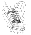
以下、本発明の車両乗降用補助ステップ装置を実施例である図面により説明すると、実施例の車両乗降用補助ステップ装置1は、図1に示すように、車両2の車室3の乗降口3a側の床面4を凹陥して凹陥ステップ部4aが設備されている。この凹陥ステップ4aの車両2では前方側である左隅に左ベース5を、車両2では後方側である右隅に右ベース6を夫々取付け、この左ベース5と右ベース6に夫々配備される同一軸線上の枢軸7、8により左L形アーム9の基部9aの基端9a1と、右L形アーム10の基部10aの基端10aを回動自在に軸支し、この左L形アーム9の先端部9bと右L形アーム10の先端部10bを、縦横所要長さで、所要の厚みを持つ方形板から構成される補助ステップ板11の基端11aより先端側の左側面11bと右側面11cに、夫々外方に突出して補助ステップ板11に同一軸線上に配備した支軸12、13により回動自在に軸支し、もって、先ず、左ベース5と右ベース6と左L形アーム9と右L形アーム10と補助ステップ板11を連結点の枢軸7、8及び支軸12、13を中心に回動自在に連結している。
DETAILED DESCRIPTION OF THE PREFERRED EMBODIMENTS Referring now to the drawings, which are embodiments of an auxiliary step device for getting on and off the vehicle according to the present invention, an
前記補助ステップ板11の基端11aに接続する右側面11cの基端11c1に、前記支軸12、13の軸線と平行の軸線の連係軸14を後方に突設している。この連係軸14と前記右ベース6との間にL形リンク15を介在して左右L形アーム9、10の回動時に支軸12、13を中心に補助ステップ板11を回動して補助ステップ板11の補助ステップへの展開と格納の折り畳みを行い、かつ、L形リンク15の基部15aと右L形アーム10の先端部10bの先端右軸支部10b1とにダンパー16を介在して操作力の軽減と作動の節度を図っている。
At the
前記左ベース5は、底板部5aに対して左右に離隔して立ち上がる左支板部5bと右支板部5cを具え、この左右支板部5b、5cに前記枢軸7の両端を支承する軸受孔(図示しない)が開孔されている。
The
前記左ベース5の左支板部5bの外側面には、ロックストッパー17が装備されており、ロック軸17aの先端が左支板部5bから突出するように内装バネ(図示しない)により付勢されており、前記左L型アーム9が格納されたとき、そのロック軸17aが前記左L型アーム9の基部9aの係合孔(図示しない)と自動的に係合し、左右L型アーム9、10を格納状態にロックするものである。
A
前記左L型アーム9の格納状態のロックを解除するには、ロックストッパー17の摘み17bを引き出すことにより、ロック軸17aがロックストッパー17内に没入して左L型アーム9の基部9aの係合孔(図示ない)との係合がなくなりロックの解除が行えるものでる。
To release the lock of the left L-shaped
前記右ベース6は、前記左ベース5と同じく底板部6aに対して左右に離隔して立ち上がる左支板部6bと右支板部6cを具え、この左右支板部6b、6cに前記枢軸8の両端を支承する軸受孔(6c1を除き図示しない)が開孔されている。
The
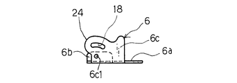
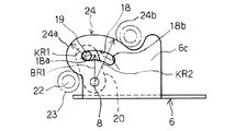
前記右ベース6は、図6に示すように、枢軸8を支承する前記軸受孔6c1を開孔する右側支板部6cに、その軸受孔6c1を中心とする所用の半径BR1の回動規制弧状孔18を開設し、基端が前記枢軸8に回転自在に支承され、前記回動規制弧状孔18に遊嵌する支軸19を先端に固着した支杆20を配備し、前記枢軸8を支点として前記支軸19を所用角度回動自在に配備し、前記L形リンク15の基部15aの基端15a1の長手方向内側に開孔した支軸受孔21に支軸19を嵌挿して回転自在に支承し、右側支板部6aの前端面と上端面を前記支軸受孔21より先端側である内側に設けたコロ軸22に回転自在に軸支されるコロ23と当接して支軸19を中心にL形リンク15を回動させるカム部24に形成している。
As shown in FIG. 6, the
前記カム部24は、前記回動規制弧状孔18の繰出側端18aを中心とする半径KR1の弧状第1ガイド面24aと、枢軸8を中心とする半径KR2の弧状第2ガイド面24bから構成されている。
The
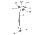
前記L形リンク15は、図8に示すように、前記右L形アーム10と同形のL形に基部15aを形成しており、その基部15aと先端部15bとの屈曲部15cの右側外面にダンパー16の基端ブラケット16aに開孔する軸受孔(図示しない)に挿通して連結するダンパー基端取付軸25が突設される。
As shown in FIG. 8, the L-shaped
前記L形リンク15の先端部15bの先端15b1に開孔する先端軸受孔26に前記補助ステップ板11の右側面の基端外側面に突設した連係軸14を挿通して回転自在に連結する。
A
前記左L形アーム9の先端部9bの先端左軸支部9b1と前記右L形アーム10の先端部10bの先端右軸支部10b1に連結するアーム連結前フレーム27の右端外面27bに外方に突出するダンパー先端連結軸28を設け、該ダンパー先端連結軸28を前記ダンパー16の先端ブラケット16bに開孔する軸受孔(図示しない)に嵌挿し、回転自在に連結している。
The left L-shaped
前記アーム連結前フレーム27の左端外面27aにハンドル29を取り付けている。
A
前記左L形アーム9において、その基部9aの左右に離隔して形成される左起立部9a11と右起立部9a12には、左軸受孔(図示しない)と右軸受孔(図示しない)が開孔され、その左軸受孔と右軸受孔の夫々には、前記枢軸7が嵌合し、また、前記右L形アーム10において、その基部10aの左右に離隔して形成させる左起立部10a11と右起立部10a12には、夫々左軸受孔(図示しない)と右軸受孔(図示しない)が開孔され、その左軸受孔と右軸受孔の夫々には、前記枢軸8が嵌合して回動自在に前記左右L形アーム9、10が支承される。
In the left L-shaped
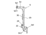
前記左L形アーム9の先端部9bにおいて、補助ステップ板11の基端の左側面に対面する先端左軸支部9b1が形成され、その先端左軸支部9b1には、軸受孔9b2が開孔されて補助ステップ板11の支軸12を嵌合し、また前記右L形アーム10の先端部10bにおいて、補助ステップ板11の基端の右側面に対面する先端右軸支部10b1が形成され、この先端右軸支部10b1には、軸受孔10b2を開孔して補助ステップ板11の支軸13が嵌合され、それらの支軸12、13を中心にして補助ステップ板11を起伏自在に支承している。
At the
前記左L形アーム9の先端部9bの先端左軸支部9b1において、補助ステップ板11の支軸12より基端の左右側面と基端との基端左隅部30に支軸12、13を中心とする展開時に上方から対面する左ストッパー部32を設け、夫々に下方に突出する左調整ボルト34を螺合して配備している。
In the distal left shaft supporting portion 9b1 of the
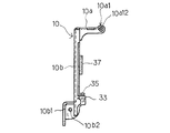
前記右L形アーム10の先端部10bの先端右軸支部10b1において、補助ステップ板11の支軸13より基端の右側面と基端との基端右隅部31に支軸12、13を中心とする展開時に上方から対面する右ストッパー部33を設け、夫々に下方に突出する右調整ボルト35を螺合して配備している。
In the distal right shaft support portion 10b1 of the
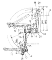
次に、図2において実線で示すように、左右L形アーム9、10が基部9a、10aの基端9a1、10a1の枢軸7、8を中心に車外に展開したとき、L形リンク15と左L形アーム9及び右L形アーム10との連係作動について、図10により説明すると、左L形アーム9と右L形アーム10が枢軸7、8を中心に乗降口3aより車外に回動し、夫々先端を下方に垂下したとき、左L形アーム9と右L形アーム10の先端部9b、10bの先端9b1、10b1の支軸12、13を中心にL形リンク15の作用で補助ステップ板11を引き上げて補助ステップ板11を水平に回動し、その角度に保持する。この水平位置において、左右ストッパー部32、33の左右調整ボルト34、35は、補助ステップ板11の基端左右隅部30、31の上面に夫々連接して乗降者の重量荷重に耐えて補助ステップ板11を水平状態に支える。
Next, as shown by the solid line in FIG. 2, when the left and right L-shaped
次に、前記左右L形アーム9、10が基部9a、10aの基端9a1、10a1の枢軸7、8を中心に車外に展開したとき、左右L形アーム連結前フレーム27の左端外面27aに支承するダンパー先端連結軸28と枢軸8との直線距離を半径AR2とすると、左右L形アーム9、10が凹陥ステップ部4aに格納されたときのダンパー先端連絡軸28とL形リンク15の基部15aのダンパー基端取付軸25との距離DR1に対して距離H分が伸長して大きいからダンパー16内のスプリング(図示しない)を伸長して復帰力を蓄積している。また、前記補助ステップ板11の重量がバランスしてハンドル29の操作を軽減している。また、ダンパー16のピストン(図示しない)に一方流通弁(図示しない)を設け、ダンパー16の先端連係軸28が繰出し作用を受けるとき、一方流通弁を閉鎖し、ピストンに開路する流通路(図示しない)を油が通過してピストンを一定のスピードで先端連係軸28を繰出し、安全なスピードで補助ステップ板11を降下・展開することができるようにしてもよいものである。
Next, when the left and right L-shaped
前記L形リンク15の基部15aの軸受孔21を右ベース6の右支板部6cに開孔した軸受け孔6c1を中心とする半径BR1で、回動規制弧状孔18内を移動できるように、軸受孔6c1に軸受けされる枢軸8に基部が回動自在に軸受けされる支杆20の先端に固着される支軸19に軸受けされるから、回動規制弧状孔18に規制され、また、カム部24の弧状第1ガイド面24aと弧状第2ガイド面24bに規制されてL形リンク15を回動する。
The bearing
前記左右L形アーム9、10の基部9a、10aと先端部9b、10bとの左右中間部9c、10cに左右緩衝ゴム座36、37が配備されて、凹陥ステップ部4aの下部外側面4a1に連接支承され、補助ステップ板11に掛かる乗降者の荷重により動揺しないように構成している。
Left and right
補助ステップ板11が図2の実線で示す位置から格納するときには、ハンドル29を握持して上方に引き上げると、左右L形アーム9、10は、左右ベース5、6の枢軸7、8を中心に回動し、支軸12、13の軌跡は、枢軸7、8と支軸12、13との距離を半径AR1である。
When the
次に、L形リンク15は、支軸19を支点として回動するが、L形リンク15の基部15aは、枢軸19を支点とすると共にコロ23をカム部24の弧状第1ガイド面24aに転接するときには、支軸19を回動規制弧状孔18の繰出端18aを中心にL形リンク15を回動する。即ち、支軸14は、支軸19を中心とする半径LR1で回動するから、上方では前記AR1の半径に対してMの距離だけ繰り出されてプラスするので、補助ステップ板11を支軸12、13を中心に基端を押し上げて左右L形アーム9、10の先端部9a、10aと同列に折り畳むものである。
Next, the L-shaped
次に、L形リンク15が支軸19を中心に回動し、コロ23が弧状第1ガイド面24aから弧状第2ガイド面24bに移動すると、支杆20の基部の枢軸8を中心する回動方向と回動規制弧状孔18の規制方向が一致するので支軸19は支杆20と共に、回動規制弧状孔18内を移動し、格納端18bに衝突する。そこで、枢軸8との関係では、補助ステップ板11を左右L形アーム9、10の先端部9b、10bの間に起立して、最小の容積に折り畳むものである。
Next, when the L-shaped
また、左右L形アーム9、10が繰り出されて垂下したとき、ダンパー基端取付軸25とダンパー先端連結軸28との距離は、DR2であるが、左右L形アーム9、10が格納されて起立したときは、Hの距離だけ縮小してDR1になるので、ダンパー16のロッド16dは、チューブ16c内に押し込まれており、内部にスプリングが配備されているときは、繰り出し時の圧縮されたスプリングの反発力で拡張してハンドル29の操作力を軽減する。そして、ロックストッパー17のロック軸17aの先端を前記左L型アーム9の基部9aの係合孔(図示しない)と自動的に係合し、左右L型アーム9、10を格納状態にロックするものである。
Further, when the left and right L-shaped
本発明の車両乗降用補助ステップ装置は、以上のようになるから、簡単・堅牢・安価な手段で対応することができるのである。 Since the auxiliary step device for getting on and off the vehicle according to the present invention is as described above, it can be handled by simple, robust, and inexpensive means.
よって、この発明の車両乗降用補助ステップ装置は、技術的に困難性がなく、ボランティアが容易に取り扱えるもので、取り扱いに画期的効果を奏するものである。 Therefore, the auxiliary step device for getting on and off the vehicle according to the present invention has no technical difficulty, can be easily handled by volunteers, and has an epoch-making effect in handling.
1 車両乗降用補助ステップ装置
2 車両
3 車室
3a 乗降口
4 床面
4a 凹陥ステップ部
4a1 下部外側面
5 左ベース
5a 底板部
5b 左支板部
5c 右支板部
6 右ベース
6a 底板部
6b 左支板部
6c 右支板部
6c1 軸受孔
7 枢軸
8 枢軸
9 左L形アーム
9a 基部
9a1 基端
9a11 左起立部
9a12 右起立部
9b 先端部
9b1 先端左軸支部
9b2 軸受孔
9c 左中間部
10 右L形アーム
10a 基部
10a1 基端
10a11 左起立部
10a12 右起立部
10b 先端部
10b1 先端右軸支部
10b2 軸受孔
10c 右中間部
11 補助ステップ板
11a 基端
11b 左側面
11c 右側面
11c1 基端右側部
12 支軸
13 支軸
14 連係軸
15 L形リンク
15a 基部
15a 基端
15b 先端部
15b1 先端
15c 屈曲部
16 ダンパー
16a 基端ブラケット
16b 先端ブラケット
16c チューブ
16d ロッド
17 ロックストッパー
17a ロック軸
17b 摘み
18 回動規制弧状孔
18a 繰出側端
18b 格納側端
19 支軸
20 支杆
21 支軸受孔
22 コロ軸
23 コロ
24 カム部
24a 弧状第1ガイド面
24b 弧状第2ガイド面
25 ダンパー基端取付軸
26 先端軸受孔
27 アーム連結前フレーム
27a 左端外面
27b 右端外面
28 ダンパー先端連結軸
29 ハンドル
30 基端左隅部
31 基端右隅部
32 左ストッパー部
33 右ストッパー部
34 左調整ボルト
35 右調整ボルト
36 左緩衝ゴム座
37 右緩衝ゴム座
AR1 半径
AR2 半径
BR1 半径
LR1 半径
LR2 半径
DR1 距離
DR2 距離
KR1 半径
KR2 半径
DESCRIPTION OF SYMBOLS 1 Vehicle entry / exit auxiliary step device 2 Vehicle 3 Car compartment 3a Entrance / exit 4 Floor surface 4a Recessed step portion 4a1 Lower outer surface 5 Left base 5a Bottom plate portion 5b Left support plate portion 5c Right support plate portion 6 Right base 6a Bottom plate portion 6b Left Support plate portion 6c Right support plate portion 6c1 Bearing hole 7 Pivot 8 Pivot 9 Left L-shaped arm 9a Base 9a1 Base end 9a11 Left standing portion 9a12 Right standing portion 9b Tip portion 9b1 Tip left shaft support portion 9b2 Bearing hole 9c Left middle portion 10 L-shaped arm 10a Base portion 10a1 Base end 10a11 Left standing portion 10a12 Right standing portion 10b Tip portion 10b1 Tip right shaft support portion 10b2 Bearing hole 10c Right middle portion 11 Auxiliary step plate 11a Base end 11b Left side surface 11c Right side portion 11c1 Base end right portion 11c1 Support shaft 13 Support shaft 14 Link shaft 15 L-shaped link 15a Base portion 15a Base end 15b Front end portion 15b1 Front end 15c Bending portion 16 Damper 16a Base end bracket 16b End bracket 16c Tube 16d Rod 17 Lock stopper 17a Lock shaft 17b Knob 18 Rotation restricting arcuate hole 18a Feeding side end 18b Storage side end 19 Support shaft 20 Support rod 21 Support bearing hole 22 Roller shaft 23 Roller 24 Cam portion 24a Arc-shaped first guide surface 24b Arc-shaped second guide surface 25 Damper base end mounting shaft 26 Tip bearing hole 27 Arm connection front frame 27a Left end outer surface 27b Right end outer surface 28 Damper tip connecting shaft 29 Handle 30 Base end Left corner 31 Base right corner 32 Left stopper 33 Right stopper 34 Left adjustment bolt 35 Right adjustment bolt 36 Left shock absorber seat 37 Right shock absorber seat AR1 radius AR2 radius BR1 radius LR1 radius LR2 radius DR1 distance DR2 distance KR1 Radius KR2 Radius
Claims (6)
Priority Applications (1)
| Application Number | Priority Date | Filing Date | Title |
|---|---|---|---|
| JP2006251865A JP4820249B2 (en) | 2006-09-15 | 2006-09-15 | Auxiliary step device for getting on and off the vehicle |
Applications Claiming Priority (1)
| Application Number | Priority Date | Filing Date | Title |
|---|---|---|---|
| JP2006251865A JP4820249B2 (en) | 2006-09-15 | 2006-09-15 | Auxiliary step device for getting on and off the vehicle |
Publications (2)
| Publication Number | Publication Date |
|---|---|
| JP2008068845A JP2008068845A (en) | 2008-03-27 |
| JP4820249B2 true JP4820249B2 (en) | 2011-11-24 |
Family
ID=39290813
Family Applications (1)
| Application Number | Title | Priority Date | Filing Date |
|---|---|---|---|
| JP2006251865A Expired - Fee Related JP4820249B2 (en) | 2006-09-15 | 2006-09-15 | Auxiliary step device for getting on and off the vehicle |
Country Status (1)
| Country | Link |
|---|---|
| JP (1) | JP4820249B2 (en) |
Families Citing this family (7)
| Publication number | Priority date | Publication date | Assignee | Title |
|---|---|---|---|---|
| JP5025595B2 (en) * | 2008-07-24 | 2012-09-12 | 日本フルハーフ株式会社 | Step device for vehicle |
| GB201001577D0 (en) * | 2010-02-01 | 2010-03-17 | Courtside Conversions Ltd | Raod vehicles |
| JP2013064239A (en) * | 2011-09-15 | 2013-04-11 | Kobelco Contstruction Machinery Ltd | Scaffold structure of construction machine |
| CN102837645B (en) * | 2012-07-20 | 2015-03-18 | 昆山西马克动力机械有限公司 | Trailer pedal |
| CN103231681B (en) * | 2013-04-17 | 2015-04-08 | 安徽江淮汽车股份有限公司 | Locking mechanism, connecting mechanism, connecting assembly and working method of locking mechanism |
| EP3659906A1 (en) * | 2018-11-27 | 2020-06-03 | Bombardier Inc. | Passenger door with deployable lower step |
| CN111645601A (en) * | 2020-05-21 | 2020-09-11 | 成都广通汽车有限公司 | Stepping structure and passenger car |
Family Cites Families (4)
| Publication number | Priority date | Publication date | Assignee | Title |
|---|---|---|---|---|
| JP2527243B2 (en) * | 1989-09-27 | 1996-08-21 | 三菱電機株式会社 | Fuel cell power generation system |
| JPH10328239A (en) * | 1997-05-30 | 1998-12-15 | Fuji Heavy Ind Ltd | Boarding and alighting auxiliary device for vehicle |
| JP2002166780A (en) * | 2000-11-29 | 2002-06-11 | Araco Corp | Folding stairway |
| JP3766800B2 (en) * | 2001-12-27 | 2006-04-19 | 株式会社トーシン | Folding stairs for vehicles |
-
2006
- 2006-09-15 JP JP2006251865A patent/JP4820249B2/en not_active Expired - Fee Related
Also Published As
| Publication number | Publication date |
|---|---|
| JP2008068845A (en) | 2008-03-27 |
Similar Documents
| Publication | Publication Date | Title |
|---|---|---|
| CN210970870U (en) | Foot pedal for motor vehicle | |
| JP4820249B2 (en) | Auxiliary step device for getting on and off the vehicle | |
| JPH1086739A (en) | Lift device for wheelchair in vehicle | |
| JP7662074B2 (en) | Vehicle boarding and alighting assistance device | |
| CN114954186A (en) | Handrail for taking on and off and sliding door mechanism | |
| US8042820B1 (en) | Driver's side large vehicle step | |
| WO2003059685A2 (en) | Wheelchair access system for a vehicle | |
| JP5161719B2 (en) | Elevating device for vehicle | |
| JP6285722B2 (en) | Front flapper device for platform in vehicle lifting device | |
| JP2005319886A (en) | Wheelchair slope device for railway vehicles | |
| JP2003127731A (en) | Getting-on and off auxiliary seat of vehicle | |
| JP2007068735A (en) | Vertically loading and unloading device for transportable fire-fighting pump | |
| JP4320626B2 (en) | Waterproof door device | |
| JP2003175760A (en) | Underfloor accommodation type lifter | |
| JP4022448B2 (en) | Anti-bending device for preventing the receiving platform from being bent | |
| US9849046B2 (en) | Occupant transfer apparatus for vehicle | |
| JP4384971B2 (en) | Seating / alighting seat for vehicles | |
| JP3089168B2 (en) | Wheelchair storage device for automobile | |
| JP2573139Y2 (en) | Truck lift equipment | |
| JP2001233148A (en) | Rush preventing device for truck | |
| JPH09142153A (en) | Wing opening/closing device for wing vehicle | |
| JP2006239067A (en) | Lifting apparatus for vehicle | |
| JP3058702U (en) | lift device | |
| JP4451261B2 (en) | Wheelchair mounted structure | |
| JP2601846Y2 (en) | Truck lift equipment |
Legal Events
| Date | Code | Title | Description |
|---|---|---|---|
| A621 | Written request for application examination |
Free format text: JAPANESE INTERMEDIATE CODE: A621 Effective date: 20090904 |
|
| A977 | Report on retrieval |
Free format text: JAPANESE INTERMEDIATE CODE: A971007 Effective date: 20110719 |
|
| TRDD | Decision of grant or rejection written | ||
| A01 | Written decision to grant a patent or to grant a registration (utility model) |
Free format text: JAPANESE INTERMEDIATE CODE: A01 Effective date: 20110726 |
|
| A01 | Written decision to grant a patent or to grant a registration (utility model) |
Free format text: JAPANESE INTERMEDIATE CODE: A01 |
|
| A61 | First payment of annual fees (during grant procedure) |
Free format text: JAPANESE INTERMEDIATE CODE: A61 Effective date: 20110902 |
|
| FPAY | Renewal fee payment (event date is renewal date of database) |
Free format text: PAYMENT UNTIL: 20140909 Year of fee payment: 3 |
|
| R150 | Certificate of patent or registration of utility model |
Free format text: JAPANESE INTERMEDIATE CODE: R150 |
|
| R250 | Receipt of annual fees |
Free format text: JAPANESE INTERMEDIATE CODE: R250 |
|
| R250 | Receipt of annual fees |
Free format text: JAPANESE INTERMEDIATE CODE: R250 |
|
| R250 | Receipt of annual fees |
Free format text: JAPANESE INTERMEDIATE CODE: R250 |
|
| R250 | Receipt of annual fees |
Free format text: JAPANESE INTERMEDIATE CODE: R250 |
|
| LAPS | Cancellation because of no payment of annual fees |
