JP4820155B2 - Corrugated duct, its construction method and chamber box - Google Patents
Corrugated duct, its construction method and chamber box Download PDFInfo
- Publication number
- JP4820155B2 JP4820155B2 JP2005343826A JP2005343826A JP4820155B2 JP 4820155 B2 JP4820155 B2 JP 4820155B2 JP 2005343826 A JP2005343826 A JP 2005343826A JP 2005343826 A JP2005343826 A JP 2005343826A JP 4820155 B2 JP4820155 B2 JP 4820155B2
- Authority
- JP
- Japan
- Prior art keywords
- duct
- corrugated
- base material
- cardboard
- corrugated cardboard
- Prior art date
- Legal status (The legal status is an assumption and is not a legal conclusion. Google has not performed a legal analysis and makes no representation as to the accuracy of the status listed.)
- Active
Links
Images


Description
この発明は、空調用や換気用等として設置される段ボール製ダクト及びその施工方法並びにチャンバーボックスに関するものである。 The present invention relates to a corrugated cardboard duct installed for air conditioning, ventilation, etc., its construction method, and a chamber box.
一般に、店舗建築等に設置される空調用ダクトには、金属製の筒体に断熱材としてグラスウールを巻き付けたものが使用されているが、このようなダクトは、重量が大きく嵩張ることから、施工現場への運搬や建築物への取り付けにコストがかかるだけでなく、撤去時に金属製の筒体からグラスウールを分離する必要があり、大量の産業廃棄物が発生するという問題がある。 In general, air conditioning ducts installed in store buildings, etc., are made of glass cylinders wrapped with glass wool as a heat insulating material. However, such ducts are heavy and bulky. Not only is it costly to transport to the site and attach to the building, but it is necessary to separate the glass wool from the metal cylinder when removed, which causes a problem that a large amount of industrial waste is generated.
その対策として、下記特許文献1,2においては、軽量で施工性や断熱性に優れ、撤去時の廃棄も容易な段ボール製のダクトが提案されている。このうち、特許文献1には、段ボールを材料とする基材に罫線を入れて、各側面板を形成し、基材を罫線に沿って側面板が角筒をなすように折り曲げ、基材の両端部を接続具で接合する構成が記載され、特許文献2には、ダクトを粘着テープで接続する構成が記載されている。
As countermeasures,
しかしながら、上記のような段ボール製ダクトでは、所定の基準を満たす不燃材として認定を受けられないため、基材の材料となる段ボールの両面にアルミ箔を貼り合わせることが考えられている。 However, since the corrugated board duct as described above cannot be certified as a non-combustible material that satisfies a predetermined standard, it is considered that aluminum foil is bonded to both sides of the corrugated cardboard that is the material of the base material.
ところが、この場合、重量やコストを考慮して、アルミ箔の厚さを50μm未満とすると、基材を罫線に沿って折り曲げた際、アルミ箔にクラックが発生し、不燃性や断熱性が低下するほか、外気が段ボール内部に侵入し、湿気により強度が低下するおそれがある。 However, in this case, considering the weight and cost, if the thickness of the aluminum foil is less than 50 μm, when the base material is bent along the ruled line, a crack occurs in the aluminum foil, and the nonflammability and the heat insulating properties are reduced. In addition, the outside air may enter the inside of the cardboard and the strength may decrease due to moisture.
また、基材を折り曲げた際に、段ボール内部の空気層が潰れて、断熱性が損われることもある。 Further, when the base material is bent, the air layer inside the cardboard may be crushed and the heat insulation may be impaired.
そこで、この発明は、薄いアルミ箔を使用しても、不燃性、断熱性及び耐湿性が確保される段ボール製ダクトを提供しようとするものである。 Therefore, the present invention is intended to provide a corrugated duct that ensures non-flammability, heat insulation and moisture resistance even when a thin aluminum foil is used.
上記課題を解決するため、この発明に係る段ボール製ダクトは、側面板が角筒をなすように罫線に沿って折り曲げる基材として、多層構造の段ボールの両面に熱可塑性樹脂を介してアルミ箔をラミネートし、また、アルミ箔の表面を塗料でコーティングして、段ボールの周縁をアルミテープでシールしたものを使用し、段目の小さい層が外側となるように基材を折り曲げたのである。 In order to solve the above-mentioned problems, a corrugated board duct according to the present invention is a base material that is bent along a ruled line so that a side plate forms a square tube. Lamination was performed, and the surface of the aluminum foil was coated with a paint, and the periphery of the cardboard was sealed with aluminum tape, and the base material was folded so that the small layer of the corrugation was outside.
この段ボール製ダクトでは、アルミ箔の表面が塗料で保護されて、基材の折曲時におけるクラックの発生が防止され、不燃性や断熱性の低下のほか、段ボール内部への外気侵入が防止されると共に、アルミテープのシールにより、基材の周縁からの着火や湿気の透過が防止される。 In this corrugated cardboard duct, the surface of the aluminum foil is protected with paint, preventing the occurrence of cracks when the base material is bent, preventing non-flammability and heat insulation, and preventing outside air from entering the corrugated cardboard. At the same time, the aluminum tape seal prevents ignition and moisture permeation from the periphery of the substrate.
また、折曲部分で変形しにくい段目の小さい層を外側としたことにより、外側部分の空気層の潰れが防止される。 Moreover, the outer layer is prevented from being crushed by forming the small layer of the step that is difficult to be deformed at the bent portion as the outside.
ここで、段目とは、段ボールの中しんの波形のことをいい、段目の大きさは、中しんの波長又は波高で表し、段目の方向は、中しんの段頂の延びる方向で表すものである。 Here, the corrugation means the corrugation of the corrugated cardboard, the corrugation size is represented by the wavelength or wave height of the corrugation, and the corrugation direction is the direction in which the top of the corrugation extends. It represents.
また、罫線とは、基材表面に設けた折曲用の溝であり、特別な治具を用いることなく、基材を所定の位置で折り曲げて、組立作業を行うことを可能とするものである。 The ruled line is a groove for bending provided on the surface of the base material, which allows the base material to be folded at a predetermined position without using a special jig and can be assembled. is there.
また、前記基材の一端の側面板に連設した継代片と、他端の側面板の端部とを重ねて、両面粘着テープで貼り合わせると共に、差込式の締結具で機械的に結合し、この継目の外側をアルミテープでシールして、基材端部の接合の位置決めをすることにより、保形性を高めると共に、基材の継目からの空気漏洩を防止することとしたのである。 In addition, the joint piece continuous to the side plate at one end of the base material and the end of the side plate at the other end are overlapped and bonded with a double-sided adhesive tape, and mechanically with a plug-in type fastener By joining and sealing the outside of this seam with aluminum tape and positioning the joining of the base material end, it was decided to improve shape retention and prevent air leakage from the joint of the base material is there.
そして、このような段ボール製ダクト同士を、例えば、前記基材と同一材料から成るソケットを用いて接続することにより、ダクトの接続部分からの空気漏洩を防止し、ワイヤ等による吊込状態での吊下強度を確保することとしたのである。 And, by connecting such cardboard ducts using, for example, a socket made of the same material as the base material, air leakage from the connecting portion of the duct is prevented, and in a suspended state by a wire or the like The suspension strength was secured.
また、前記段ボール製ダクトにより角筒状の本体を形成し、その両端に端板を被せ、下穴を開けて、ダクトを接続するカラーを取り付けたチャンバーボックスを製作し、チャンバーボックスの不燃性や断熱性を確保することとしたのである。 In addition, a rectangular tube-shaped main body is formed by the corrugated cardboard duct, end plates are put on both ends, a pilot hole is opened, and a chamber box with a collar for connecting the duct is manufactured. It was decided to ensure heat insulation.
この段ボール製ダクトでは、基材の段ボールの両面にアルミ箔をラミネートして、その表面を塗料でコーティングしたので、アルミ箔の表面が柔軟に保護され、アルミ箔が薄くても、基材の折り曲げに伴うアルミ箔のクラック発生が防止される。 In this corrugated cardboard duct, aluminum foil is laminated on both sides of the corrugated board of the base material, and the surface is coated with paint, so the surface of the aluminum foil is flexibly protected, and even if the aluminum foil is thin, the base material can be bent. The occurrence of cracks in the aluminum foil is prevented.
このため、クラックからの段ボールの露出による不燃性や断熱性の低下が防止され、結露による強度低下も防止される。 For this reason, the nonflammability and heat insulation fall by exposure of the corrugated cardboard from a crack are prevented, and the strength fall by dew condensation is also prevented.
また、段ボールの周縁をアルミテープでシールしたので、基材の周縁での段ボールの露出による不燃性の低下や、断熱性の低下も防止される。 Moreover, since the periphery of the corrugated cardboard is sealed with the aluminum tape, non-flammability deterioration and heat insulation deterioration due to exposure of the corrugated cardboard at the peripheral edge of the base material are prevented.
また、基材の接合を両面粘着テープ及び差込式の締結具で行い、継目の外側をアルミテープでシールしたので、接合の位置決めが正確化され、保形性が高められると共に、基材の継目からの空気漏洩が防止されて、優れた断熱性が得られる。 In addition, the base material is joined with a double-sided adhesive tape and a plug-in type fastener, and the outside of the seam is sealed with aluminum tape, so that the positioning of the joint is made accurate and the shape retention is improved. Air leakage from the seam is prevented, and excellent heat insulation is obtained.
さらに、軽量の基材を扁平に展開した状態で運搬できるので、輸送コストを削減でき、基材を展開状態から折り曲げることにより、簡単に組み立てることができるほか、ソケットを使用したダクトの接続や吊り込み等、施工作業も容易に行うことができる。 In addition, since lightweight substrates can be transported in a flattened state, transportation costs can be reduced, and the substrate can be easily assembled by folding it from the unfolded state, as well as connecting and hanging ducts using sockets. Construction work can be easily performed.
以下、この発明の実施の形態を添付図面に基づいて説明する。 Embodiments of the present invention will be described below with reference to the accompanying drawings.
この段ボール製ダクトは、空調用として設置されるものであり、図1に示すような基材Mから形成される。ダクトの大きさは、例えば、図5に示す組立状態において、内寸が400mm×300mmとなり、長さが1500mmとなるように設定されている。なお、複数枚の基材を周方向に継ぎ合わせて製作する場合には、例えば、内寸が600mm×600mm程度となるような大口径のダクトを形成することもできる。このとき、基材同士の継目は、端部同士を重ねて、両面粘着テープで貼り合わせると共に、差込式の締結具で機械的に結合し、この継目の外側をアルミテープでシールすることが望ましい。 This cardboard duct is installed for air conditioning, and is formed from a base material M as shown in FIG. For example, in the assembled state shown in FIG. 5, the size of the duct is set so that the inner dimension is 400 mm × 300 mm and the length is 1500 mm. When manufacturing a plurality of base materials joined together in the circumferential direction, for example, a large-diameter duct having an inner dimension of about 600 mm × 600 mm can be formed. At this time, the seams between the base materials can be bonded to each other with double-sided adhesive tape and mechanically joined with an insertion-type fastener, and the outside of the seam can be sealed with aluminum tape. desirable.
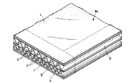
このダクトを構成する基材Mは、図2に示すような多層の断面構造となっており、複両面段ボール1の両面に、接着剤、例えば熱可塑性樹脂であるポリエチレン2を介してアルミニウムを薄く延ばしたアルミ箔3をラミネートし、アルミ箔3の表面を塗料4でコーティングしたものとされている。
The base material M constituting the duct has a multilayer cross-sectional structure as shown in FIG. 2, and aluminum is thinly formed on both sides of the double-
ここで、段ボール1としては、各層の段目の大きさの比が1:1.2〜1:2となるようにするのが好ましい。例えば、全体の厚さが約8mmであって、段目の大きい内側段の厚さが約5mm、段目の小さい外側段の厚さが約3mmのものを用いるとよい。また、この場合、段ボール1の中間のライナ5の厚さは0.2mm、外側両面のライナ6の厚さは0.32mm、中しん7の厚さは0.2mm以下とし、内側段の波長は9mm、外側段の波長は6mm以上とするのがよい。
Here, as the
そして、アルミ箔3の厚さは7〜50μm(好ましくは20μm程度)とし、折り曲げ時のクラック発生防止の点から、アルミ箔3には軟質アルミ箔を用いるのが好ましく、押出ラミネートするポリエチレン2の着量は10〜30g/m2、塗布する塗料4の着量は0.5〜2.0g/m2とするのが機能面及び重量・コスト面から好ましい。
The thickness of the
また、アルミ箔3のラミネート及び塗料4の塗布は、ライナ6が原紙の段階で行い、その後、ライナ6をコルゲータの熱板で押圧しつつ中しん7と貼り合わせるので、塗料4としては、ニトロセルロース系樹脂のニス等、耐熱性に優れたものが用いられる。
In addition, the lamination of the
このような基材Mにおいて、段ボール1の周縁は、図3に示すように、アルミ箔の片面に粘着力を付与したアルミテープ8(鎖線で表示)を貼り付けてシールされ、基材Mの周縁で段ボール1が露出しないようになっている。
In such a base material M, as shown in FIG. 3, the periphery of the
そして、基材Mには、図1に示すように、段ボール1の段目に直交する方向に罫線9を入れて、各一対の側面板10,11及び継代片12を形成し、基材Mの一端の継代片12と、他端の側面板11の端部には、ピン穴13を複数個ずつ設ける。また、他端の側面板11の両側部にもピン穴14を1個又は必要により複数個ずつ設ける。
Then, as shown in FIG. 1, a
上記のような基材MをダクトDに組み立てるには、図4及び図5に示すように、基材Mを罫線9に沿って各一対の側面板10,11が角筒をなすように折り曲げる。このとき、罫線9が段ボール1の段目に直交しているので、基材Mは段目の影響を受けることなく、罫線9に沿って正確な位置で折れ曲がり、精度のよい角筒が形成される。
In order to assemble the base material M as described above into the duct D, as shown in FIGS. 4 and 5, the base material M is bent along the
そして、継代片12の外面に予め貼り付けておいた両面粘着テープ15(図4に鎖線で表示)により、継代片12と他端の側面板11とを重ねた状態で貼り合わせ、ピン穴13に締結具16を差し込んで、基材Mの両端部を接合し、その継目の外側をアルミテープ17(図5に鎖線で表示)でシールする。
Then, the double-sided adhesive tape 15 (indicated by a chain line in FIG. 4) previously attached to the outer surface of the
ここで、締結具16としては、図14に示すように、ピン穴13に差し込んで頭部16aを押すと、爪16bが拡径して内側の基材Mに嵌めたフランジ部材16cの挿通穴から抜け止めされるプラスチック製の締結ピンや、図15に示すように、一方の基材Mに取り付けた凸部材16dを、他方の基材Mに取り付けた凹部材16eに押し込んで係合させるプラスチック製の締結ボタンを用いるとよい。
Here, as the
このように、両面粘着テープ15及びアルミテープ17による接着だけでなく、締結具16により機械的に締結しておくと、両面粘着テープ15及びアルミテープ17によるシール効果が得られるだけでなく、基材Mの接合の位置決めを正確に行うことができ、経年変化でテープ15,17の接着力が低下した場合でも、ダクトの形状が維持される。
Thus, not only the adhesion by the double-sided pressure-sensitive
このような段ボール製ダクトDでは、基材Mの段ボール1の両面にポリエチレン2を介してアルミ箔3をラミネートし、その表面を塗料4でコーティングしたので、基材Mの表面粗さが改善され、圧力損失が低減されると共に、アルミ箔3の表面が柔軟に保護され、また、アルミ箔3と段ボール1のライナとの伸び率の差がポリエチレン2の弾性で吸収されるので、ポリエチレン2と塗料4の相乗効果により、基材Mの折り曲げに伴うアルミ箔3のクラック発生が防止される。
In such a corrugated cardboard duct D, the
このため、罫線9に沿った稜部におけるクラックからの段ボール1の露出による不燃性の低下や、防湿性が損なわれることに伴う断熱性の低下が防止され、結露による強度低下も防止される。
For this reason, the nonflammability fall by exposure of the
また、段ボール1の周縁をアルミテープ8でシールしたので、基材Mの周縁での段ボール1の露出による不燃性の低下や、断熱性の低下も防止される。
Moreover, since the periphery of the
さらに、軽量の基材Mを扁平に展開した状態で施工現場へ運搬できるので、輸送コストを削減でき、基材Mを展開状態から折り曲げることにより、簡単に組み立てることができるので、現場での作業負荷が増大することもない。 Furthermore, since the lightweight base material M can be transported to the construction site in a flat state, the transportation cost can be reduced, and the base material M can be easily assembled by folding it from the expanded state. The load does not increase.
なお、この組立状態において、図5に示すように基材Mを使用すると、段目の小さい外側段部分の空気層の潰れが防止されると共に、基材Mの表面が平滑となって輻射熱の反射効率が高くなるので、断熱性等が向上するほか、罫線9に沿った折曲時にアルミ箔3にクラックが発生しにくくなり、美観にも優れたものとなる。
In this assembled state, when the base material M is used as shown in FIG. 5, the air layer in the outer step portion having a small step is prevented from being crushed, and the surface of the base material M is smoothed to generate radiant heat. Since the reflection efficiency is increased, heat insulation and the like are improved, and the
次に、上記のように組み立てたダクトDを接続するには、まず、図6に示すように、ダクトD同士を突き合わせ、その突合部をアルミテープ18(鎖線で表示)の巻き付けによりシールする。なお、この巻き付けに先立って、ダクトDの端部同士を短く切断したアルミテープで仮止めしておくと、突合部への巻き付けを容易に行うことができる。 Next, in order to connect the duct D assembled as described above, first, as shown in FIG. 6, the ducts D are butted together and the abutting portion is sealed by winding an aluminum tape 18 (indicated by a chain line). Prior to this winding, if the ends of the duct D are temporarily fixed with an aluminum tape that has been cut short, the winding around the abutting portion can be easily performed.
続いて、図7に示すように、ダクトDの突合部の外周に、基材Mと同一材料の帯材から成るソケットSを罫線19に沿って折り曲げつつ巻き付ける。この罫線19は、ソケットSの内周がダクトDの外周よりも少し大きくなる位置に入れておく。
Subsequently, as shown in FIG. 7, a socket S made of a strip made of the same material as the base material M is wound around the outer periphery of the abutting portion of the duct D while being bent along the ruled
その後、側面板11のピン穴14及びソケットSに設けたピン穴を利用して、ダクトDとソケットSとを締結具16で結合すると共に、ソケットSの両端の重合部20を、その部分に設けたピン穴を利用して、締結具16で結合する。
Thereafter, using the pin holes 14 of the
このように、ダクトDをアルミテープ18だけでなく、ソケットSで包囲して機械的に補強しつつ接続すると、建築物に吊り込んで取り付けた状態において、接続部が屈曲するような変形が防止される。
In this way, when the duct D is connected not only with the
なお、締結具16として、図14に示すような締結ピンを使用した場合、ダクトDの内部には、締結具16の先端部が突出するが、突出量は8mm程度と僅かであるため、管内の圧力損失には大きな影響はないと考えられる。
When a fastening pin as shown in FIG. 14 is used as the
また、ダクトDと丸ダクトとを接続するには、図8に示すように、丸ダクトの端部が差し込まれる取出しカラー21をダクトDに取り付ける。
Further, in order to connect the duct D and the round duct, the take-out
この取出しカラー21をダクトDの組立時に予め取り付けておく場合には、ダクトDに下穴22を開け、ダクトDの内側からシーリング剤を塗布した取出しカラー21の円筒部を下穴22に挿入して外側へ突出させ、取出しカラー21のフランジ部をダクトDの内面に沿わせて、締結具16により固定する。
When the take-out
また、取出しカラー21をダクトDの設置後に取り付ける場合でも、ダクトDが建築物に取り付けられたままの状態で、ダクトDに簡単に下穴22を開けることができるので、取出しカラー21のフランジをダクトDの外側から下穴22の周囲に当接して、締結具16で固定することにより、丸ダクトを容易に接続することができる。なお、取出しカラー21を角筒状として、同様の方法により、角形ダクトを接続することもできる。
Even when the take-out
一方、この段ボール製ダクトDを建築物に吊り込む際には、図9に示すように、通常のスチール製ダクトと同様、天井から垂下する2本の吊下ボルト23の下端間にアングル材24を渡し、このアングル材24でダクトDを受け止める方法を採用することもできる。
On the other hand, when the corrugated duct D is suspended in the building, as shown in FIG. 9, the
しかしながら、このような吊り込み方法の他にも、段ボール製のダクトDがスチール製のものよりも大幅に軽量であることを活かして、以下のような吊り込み方法を採用することにより、コストダウンを図ることも考えられる。 However, in addition to such a hanging method, taking advantage of the fact that the corrugated duct D is significantly lighter than the steel one, it is possible to reduce the cost by adopting the following hanging method. It is also possible to plan.
その一つとして、図10に示すように、ダクトDの一対の側面板11にリングピン25を差し込んでおき、2本の吊下ボルト23とリングピン25とをワイヤ26で繋ぐ吊り込み方法が可能となる。
As one of them, as shown in FIG. 10, there is a suspension method in which a
また、図11に示すように、ダクトDの一対の側面板11に差し込んだリングピン25間に1本のワイヤ27を渡し、このワイヤ27を1本の吊下ボルト23に掛けて吊り込む方法も可能となる。
Further, as shown in FIG. 11, a method of passing one
また、図12に示すように、ダクトDの下面から両側面にベルト28を沿わせ、その両端部間に1本のワイヤ27を渡し、このワイヤ27を1本の吊下ボルト23に掛けて吊り込む方法も可能となる。
Further, as shown in FIG. 12, a
さらに、図13に示すように、ダクトDを接続する金属製ニップルTにワイヤ26を挿通する吊穴33を設け、吊下ボルト23とニップルTとをワイヤ26で繋いで吊り込むこともできる。この場合、ニップルTとして、ダクトDの内側に差し込まれる差込筒部34の中央部外周に、ダクトDの端面が当接するフランジ35を設けたものを用い、フランジ35に吊穴33を形成するとよい。
Further, as shown in FIG. 13, a
そのほか、ダクトDに複数の他のダクトを接続する場合には、図16に示すように、ダクトDに連通して取り付けるチャンバーボックス29として、ダクトDと同様の基材Mを使用して同様の工法で角筒状の本体30を製作し、その両端に、角筒状に継ぎ合わせた縁板を有する端板31を被せ、本体30及び端板31に適宜下穴を開けて複数のカラー32を取り付けたものを使用すればよい。
In addition, when connecting a plurality of other ducts to the duct D, as shown in FIG. 16, the same base material M as the duct D is used as the
D ダクト
M 基材
1 段ボール
2 ポリエチレン
3 アルミ箔
4 塗料
5,6 ライナ
7 中しん
8 アルミテープ
9 罫線
10,11 側面板
12 継代片
13,14 ピン穴
15 両面粘着テープ
16 締結具
17,18 アルミテープ
S ソケット
19 罫線
20 重合部
21 取出しカラー
22 下穴
23 吊下ボルト
24 アングル材
25 リングピン
26,27 ワイヤ
28 ベルト
29 チャンバーボックス
30 本体
31 端板
32 カラー
T ニップル
33 吊穴
34 差込筒部
35 フランジ
D Duct
Claims (10)
Priority Applications (1)
| Application Number | Priority Date | Filing Date | Title |
|---|---|---|---|
| JP2005343826A JP4820155B2 (en) | 2005-11-29 | 2005-11-29 | Corrugated duct, its construction method and chamber box |
Applications Claiming Priority (1)
| Application Number | Priority Date | Filing Date | Title |
|---|---|---|---|
| JP2005343826A JP4820155B2 (en) | 2005-11-29 | 2005-11-29 | Corrugated duct, its construction method and chamber box |
Publications (2)
| Publication Number | Publication Date |
|---|---|
| JP2007147185A JP2007147185A (en) | 2007-06-14 |
| JP4820155B2 true JP4820155B2 (en) | 2011-11-24 |
Family
ID=38208790
Family Applications (1)
| Application Number | Title | Priority Date | Filing Date |
|---|---|---|---|
| JP2005343826A Active JP4820155B2 (en) | 2005-11-29 | 2005-11-29 | Corrugated duct, its construction method and chamber box |
Country Status (1)
| Country | Link |
|---|---|
| JP (1) | JP4820155B2 (en) |
Cited By (1)
| Publication number | Priority date | Publication date | Assignee | Title |
|---|---|---|---|---|
| KR101715603B1 (en) * | 2016-04-21 | 2017-03-13 | 대원실업 주식회사 | Aluminum foil layered double corrugated board |
Families Citing this family (17)
| Publication number | Priority date | Publication date | Assignee | Title |
|---|---|---|---|---|
| JP5111971B2 (en) * | 2007-08-02 | 2013-01-09 | 株式会社栗本鐵工所 | Corrugated board assembly duct |
| JP5002503B2 (en) * | 2008-03-21 | 2012-08-15 | 大成建設株式会社 | Nipple connection method for corrugated duct |
| JP5528720B2 (en) * | 2009-04-22 | 2014-06-25 | 大成建設株式会社 | Air outlet device |
| JP3156870U (en) * | 2009-11-05 | 2010-01-21 | 有限会社テクノフロンティア | Heat exchange structure |
| JP2011102648A (en) * | 2009-11-10 | 2011-05-26 | Kyoritsu Air Tech Inc | Ventilator |
| JP5466490B2 (en) * | 2009-11-17 | 2014-04-09 | 三建設備工業株式会社 | Corrugated cardboard duct base material and corrugated cardboard member manufacturing method |
| JP4779055B2 (en) * | 2010-01-12 | 2011-09-21 | 卓一 望月 | Ventilation passage assembly kit |
| KR101029559B1 (en) | 2010-11-22 | 2011-04-15 | (주)세이크엠이씨 | Air duct made of corrugated board |
| US9200729B2 (en) | 2013-05-24 | 2015-12-01 | Paul E. HOBBS | Combination hanger and reinforcement bracket |
| JP6301187B2 (en) * | 2014-05-13 | 2018-03-28 | レンゴー株式会社 | Laminate sheet for offshore target and offshore target using the same |
| JP6618715B2 (en) * | 2015-06-19 | 2019-12-11 | 協立エアテック株式会社 | Air conditioning chamber installation structure |
| CN105156774A (en) * | 2015-08-06 | 2015-12-16 | 中交一航局安装工程有限公司 | Manufacturing and mounting process for composite phenolic aldehyde aluminum foil air pipes |
| JP2017156051A (en) * | 2016-03-04 | 2017-09-07 | 協立エアテック株式会社 | Air conditioning chamber |
| JP7052984B2 (en) * | 2017-09-01 | 2022-04-12 | トヨタホーム株式会社 | Air conditioning chamber and air conditioning equipment |
| JP2020020530A (en) * | 2018-08-01 | 2020-02-06 | 株式会社竹中工務店 | Corrugated board duct |
| JP7308738B2 (en) | 2019-12-09 | 2023-07-14 | フジモリ産業株式会社 | Branch chamber for air conditioning |
| JP7250385B1 (en) | 2022-07-14 | 2023-04-03 | 日本グランデ株式会社 | Chamber box type charcoal power clean system |
Family Cites Families (19)
| Publication number | Priority date | Publication date | Assignee | Title |
|---|---|---|---|---|
| JPS489694Y1 (en) * | 1970-06-19 | 1973-03-14 | ||
| JPH0242805Y2 (en) * | 1984-09-19 | 1990-11-15 | ||
| JPS61109981U (en) * | 1984-12-25 | 1986-07-11 | ||
| JPH0129076Y2 (en) * | 1986-05-02 | 1989-09-05 | ||
| JP2514210B2 (en) * | 1987-07-23 | 1996-07-10 | 日産自動車株式会社 | Method for etching semiconductor substrate |
| JPH0293214U (en) * | 1989-01-11 | 1990-07-24 | ||
| JPH0332367A (en) * | 1989-06-28 | 1991-02-12 | Fuji Electric Co Ltd | Controller for power source apparatus |
| JPH0389094A (en) * | 1989-08-30 | 1991-04-15 | Sumitomo Metal Ind Ltd | Thermoplastic pipe joint and manufacture thereof |
| JPH062043U (en) * | 1992-06-11 | 1994-01-14 | 大成建設株式会社 | Assembled duct |
| JPH08338569A (en) * | 1995-01-24 | 1996-12-24 | Asano Seiki:Kk | Suspender metal and suspending/supporting method |
| JPH08267628A (en) * | 1995-03-30 | 1996-10-15 | Sekisui Chem Co Ltd | Flame-retardant composite heat insulating material and heat insulating material for air conditioning duct for rooling stock |
| JP3533586B2 (en) * | 1995-04-14 | 2004-05-31 | 協立エアテック株式会社 | Flexible duct suspension device |
| JP2996907B2 (en) * | 1995-12-15 | 2000-01-11 | 鹿島建設株式会社 | Duct unit and its on-site assembly method |
| JP3856921B2 (en) * | 1997-09-24 | 2006-12-13 | ティーオーエー株式会社 | Packing material for equipment packing |
| JP4291447B2 (en) * | 1999-03-10 | 2009-07-08 | トーセツ株式会社 | Air duct installation method |
| JP2002267245A (en) * | 2001-03-12 | 2002-09-18 | Hitachi Plant Eng & Constr Co Ltd | Duct |
| JP3584445B2 (en) * | 2001-10-16 | 2004-11-04 | 株式会社栗本鐵工所 | Air-conditioning chamber duct connection structure |
| JP2004036992A (en) * | 2002-07-03 | 2004-02-05 | Japan Aibitsuku:Kk | Duct and hanging metal piece for duct |
| JP4450641B2 (en) * | 2004-02-20 | 2010-04-14 | 株式会社ジャパンアイビック | Flexible joint material for ducts |
-
2005
- 2005-11-29 JP JP2005343826A patent/JP4820155B2/en active Active
Cited By (1)
| Publication number | Priority date | Publication date | Assignee | Title |
|---|---|---|---|---|
| KR101715603B1 (en) * | 2016-04-21 | 2017-03-13 | 대원실업 주식회사 | Aluminum foil layered double corrugated board |
Also Published As
| Publication number | Publication date |
|---|---|
| JP2007147185A (en) | 2007-06-14 |
Similar Documents
| Publication | Publication Date | Title |
|---|---|---|
| JP4820155B2 (en) | Corrugated duct, its construction method and chamber box | |
| JP6622155B2 (en) | Insulation duct products | |
| CA2110430C (en) | Laminated non-combustible board for forming ductwork and headers | |
| US6901711B2 (en) | Facing and faced building insulation | |
| US20040123539A1 (en) | Facing and faced insulation assembly | |
| JP4791428B2 (en) | Duct connection structure | |
| WO2007086737A1 (en) | Wall element | |
| JP5111971B2 (en) | Corrugated board assembly duct | |
| JP5002503B2 (en) | Nipple connection method for corrugated duct | |
| JP2008292024A (en) | Noncombustible heat insulating duct | |
| CN201218387Y (en) | Fast-fixing heat insulation plate of air distribution pipe | |
| JP5843139B2 (en) | Paper round cylindrical duct | |
| JPH0630140U (en) | Heat-insulating adhesive sheet | |
| KR20090012441A (en) | A method for producing a lightened duct and ducts made thereby | |
| JP2006063794A (en) | Wall member | |
| JP4675069B2 (en) | Corrugated duct assembly structure | |
| JP2000038884A (en) | Winding structure for shutter curtain | |
| JP4524198B2 (en) | Thermal insulation panel for curved surface in heat storage tank and method of attaching heat insulating material to curved surface of heat storage tank using the same | |
| KR200372035Y1 (en) | Fixed structure of heat contractility band | |
| JP2007205695A (en) | Flexible duct and its manufacturing method | |
| JP5466490B2 (en) | Corrugated cardboard duct base material and corrugated cardboard member manufacturing method | |
| JP2023124296A (en) | Foldable duct and method for manufacturing the same | |
| JP2015017746A (en) | Corrugated cardboard duct | |
| JP2003232466A (en) | Piping method in building | |
| JPH10196882A (en) | Pipe body heat insulating material protection cylinder and pipe body insulating material protecting tool |
Legal Events
| Date | Code | Title | Description |
|---|---|---|---|
| A621 | Written request for application examination |
Free format text: JAPANESE INTERMEDIATE CODE: A621 Effective date: 20080819 |
|
| A131 | Notification of reasons for refusal |
Free format text: JAPANESE INTERMEDIATE CODE: A131 Effective date: 20110215 |
|
| A521 | Request for written amendment filed |
Free format text: JAPANESE INTERMEDIATE CODE: A523 Effective date: 20110415 |
|
| TRDD | Decision of grant or rejection written | ||
| A01 | Written decision to grant a patent or to grant a registration (utility model) |
Free format text: JAPANESE INTERMEDIATE CODE: A01 Effective date: 20110809 |
|
| A01 | Written decision to grant a patent or to grant a registration (utility model) |
Free format text: JAPANESE INTERMEDIATE CODE: A01 |
|
| A61 | First payment of annual fees (during grant procedure) |
Free format text: JAPANESE INTERMEDIATE CODE: A61 Effective date: 20110902 |
|
| FPAY | Renewal fee payment (event date is renewal date of database) |
Free format text: PAYMENT UNTIL: 20140909 Year of fee payment: 3 |
|
| R150 | Certificate of patent or registration of utility model |
Ref document number: 4820155 Country of ref document: JP Free format text: JAPANESE INTERMEDIATE CODE: R150 Free format text: JAPANESE INTERMEDIATE CODE: R150 |
|
| R250 | Receipt of annual fees |
Free format text: JAPANESE INTERMEDIATE CODE: R250 |
|
| R250 | Receipt of annual fees |
Free format text: JAPANESE INTERMEDIATE CODE: R250 |
|
| R250 | Receipt of annual fees |
Free format text: JAPANESE INTERMEDIATE CODE: R250 |
|
| R250 | Receipt of annual fees |
Free format text: JAPANESE INTERMEDIATE CODE: R250 |
|
| R250 | Receipt of annual fees |
Free format text: JAPANESE INTERMEDIATE CODE: R250 |
|
| R250 | Receipt of annual fees |
Free format text: JAPANESE INTERMEDIATE CODE: R250 |
|
| R250 | Receipt of annual fees |
Free format text: JAPANESE INTERMEDIATE CODE: R250 |