JP4819633B2 - Belt type continuously variable transmission for saddle riding type vehicle and saddle riding type vehicle - Google Patents
Belt type continuously variable transmission for saddle riding type vehicle and saddle riding type vehicle Download PDFInfo
- Publication number
- JP4819633B2 JP4819633B2 JP2006260952A JP2006260952A JP4819633B2 JP 4819633 B2 JP4819633 B2 JP 4819633B2 JP 2006260952 A JP2006260952 A JP 2006260952A JP 2006260952 A JP2006260952 A JP 2006260952A JP 4819633 B2 JP4819633 B2 JP 4819633B2
- Authority
- JP
- Japan
- Prior art keywords
- case
- belt
- primary
- continuously variable
- variable transmission
- Prior art date
- Legal status (The legal status is an assumption and is not a legal conclusion. Google has not performed a legal analysis and makes no representation as to the accuracy of the status listed.)
- Active
Links
Images


Classifications
-
- F—MECHANICAL ENGINEERING; LIGHTING; HEATING; WEAPONS; BLASTING
- F16—ENGINEERING ELEMENTS AND UNITS; GENERAL MEASURES FOR PRODUCING AND MAINTAINING EFFECTIVE FUNCTIONING OF MACHINES OR INSTALLATIONS; THERMAL INSULATION IN GENERAL
- F16H—GEARING
- F16H57/00—General details of gearing
- F16H57/02—Gearboxes; Mounting gearing therein
- F16H57/025—Support of gearboxes, e.g. torque arms, or attachment to other devices
-
- F—MECHANICAL ENGINEERING; LIGHTING; HEATING; WEAPONS; BLASTING
- F16—ENGINEERING ELEMENTS AND UNITS; GENERAL MEASURES FOR PRODUCING AND MAINTAINING EFFECTIVE FUNCTIONING OF MACHINES OR INSTALLATIONS; THERMAL INSULATION IN GENERAL
- F16H—GEARING
- F16H57/00—General details of gearing
- F16H57/04—Features relating to lubrication or cooling or heating
- F16H57/0412—Cooling or heating; Control of temperature
- F16H57/0415—Air cooling or ventilation; Heat exchangers; Thermal insulations
-
- F—MECHANICAL ENGINEERING; LIGHTING; HEATING; WEAPONS; BLASTING
- F16—ENGINEERING ELEMENTS AND UNITS; GENERAL MEASURES FOR PRODUCING AND MAINTAINING EFFECTIVE FUNCTIONING OF MACHINES OR INSTALLATIONS; THERMAL INSULATION IN GENERAL
- F16H—GEARING
- F16H57/00—General details of gearing
- F16H57/04—Features relating to lubrication or cooling or heating
- F16H57/048—Type of gearings to be lubricated, cooled or heated
- F16H57/0487—Friction gearings
- F16H57/0489—Friction gearings with endless flexible members, e.g. belt CVTs
-
- F—MECHANICAL ENGINEERING; LIGHTING; HEATING; WEAPONS; BLASTING
- F16—ENGINEERING ELEMENTS AND UNITS; GENERAL MEASURES FOR PRODUCING AND MAINTAINING EFFECTIVE FUNCTIONING OF MACHINES OR INSTALLATIONS; THERMAL INSULATION IN GENERAL
- F16H—GEARING
- F16H9/00—Gearings for conveying rotary motion with variable gear ratio, or for reversing rotary motion, by endless flexible members
- F16H9/02—Gearings for conveying rotary motion with variable gear ratio, or for reversing rotary motion, by endless flexible members without members having orbital motion
- F16H9/04—Gearings for conveying rotary motion with variable gear ratio, or for reversing rotary motion, by endless flexible members without members having orbital motion using belts, V-belts, or ropes
- F16H9/12—Gearings for conveying rotary motion with variable gear ratio, or for reversing rotary motion, by endless flexible members without members having orbital motion using belts, V-belts, or ropes engaging a pulley built-up out of relatively axially-adjustable parts in which the belt engages the opposite flanges of the pulley directly without interposed belt-supporting members
- F16H9/16—Gearings for conveying rotary motion with variable gear ratio, or for reversing rotary motion, by endless flexible members without members having orbital motion using belts, V-belts, or ropes engaging a pulley built-up out of relatively axially-adjustable parts in which the belt engages the opposite flanges of the pulley directly without interposed belt-supporting members using two pulleys, both built-up out of adjustable conical parts
- F16H9/18—Gearings for conveying rotary motion with variable gear ratio, or for reversing rotary motion, by endless flexible members without members having orbital motion using belts, V-belts, or ropes engaging a pulley built-up out of relatively axially-adjustable parts in which the belt engages the opposite flanges of the pulley directly without interposed belt-supporting members using two pulleys, both built-up out of adjustable conical parts only one flange of each pulley being adjustable
-
- F—MECHANICAL ENGINEERING; LIGHTING; HEATING; WEAPONS; BLASTING
- F16—ENGINEERING ELEMENTS AND UNITS; GENERAL MEASURES FOR PRODUCING AND MAINTAINING EFFECTIVE FUNCTIONING OF MACHINES OR INSTALLATIONS; THERMAL INSULATION IN GENERAL
- F16H—GEARING
- F16H57/00—General details of gearing
- F16H57/02—Gearboxes; Mounting gearing therein
- F16H2057/0203—Gearboxes; Mounting gearing therein the gearbox is associated or combined with a crank case of an engine
Abstract
Description
本発明は、鞍乗型車両(例えば、自動二輪車)用のベルト式無段変速機、及び、ベルト式無段変速機が搭載された鞍乗型車両に関する。 The present invention relates to a belt type continuously variable transmission for a saddle type vehicle (for example, a motorcycle) and a saddle type vehicle equipped with the belt type continuously variable transmission.
スクータ型の自動二輪車等の鞍乗型車両には、広くVベルト式無段変速機が使われている。このVベルト式無段変速機は、エンジン等の動力源の出力が入力されるプライマリ軸と、駆動輪への出力を取り出すセカンダリ軸とにそれぞれ配された溝幅可変の一対のプライマリシーブ及びセカンダリシーブで構成され、両シーブにVベルトを巻掛し、溝幅調節機構により各シーブの溝幅を変えることで、Vベルトの各シーブに対する巻掛け径を調節し、それにより両シーブ間で変速比を無段階的に調節するというものである。 V-belt type continuously variable transmissions are widely used in straddle-type vehicles such as scooter type motorcycles. This V-belt type continuously variable transmission includes a pair of primary sheaves and secondarys with variable groove widths arranged on a primary shaft to which an output of a power source such as an engine is input and a secondary shaft that extracts output to drive wheels, respectively. Consists of sheaves, V-belts are wrapped around both sheaves, and the groove width of each sheave is changed by the groove width adjustment mechanism to adjust the winding diameter of each sheave of the V-belt, thereby shifting between the sheaves The ratio is adjusted steplessly.
通常、プライマリシーブ及びセカンダリシーブは、相互間にV溝を形成する固定フランジ及び可動フランジとから構成され、各可動フランジがプライマリ軸又はセカンダリ軸の軸線方向に移動自在に設けられている。そして、溝幅調節機構により可動フランジを移動させることによって、変速比を無段階に調節できるようになっている。 Usually, the primary sheave and the secondary sheave are composed of a fixed flange and a movable flange that form a V-groove therebetween, and each movable flange is provided so as to be movable in the axial direction of the primary shaft or the secondary shaft. The gear ratio can be adjusted steplessly by moving the movable flange by the groove width adjusting mechanism.
従来、この種のVベルト式無段変速機として、溝幅調節のためのプライマリシーブの可動フランジの移動を電動モータで行うようにしたものがある。斯かるベルト式無段変速機は、電動モータの移動推力により、プライマリシーブの溝幅を狭める方向(Top側)、及び溝幅を広げる方向(Low側)のいずれの方向にも可動フランジを移動させることができるので、プライマリシーブの溝幅を自由に調節することができる(例えば、特許文献1等参照)。
本発明者は、鞍乗型車両用のベルト式無段変速機について、今までにない新規な鞍乗型車両用のベルト式無段変速機を開発している。 The present inventor has developed a belt-type continuously variable transmission for a saddle-type vehicle that has never been developed as a belt-type continuously variable transmission for a saddle-type vehicle.
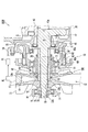
当該開発中の新規な鞍乗型車両用のベルト式無段変速機1000に関し、プライマリシーブ周辺部を図1に示す。図1中の11はプライマリ軸を、12はプライマリシーブを、13は溝幅調節機構を、17はVベルトを、30はクランク部を、42はクランクウエブを、51は固定フランジを、52は可動フランジをそれぞれ示している。また、プライマリ軸11のクランクジャーナル41とケース14との間には、すべり軸受41aを介在させており、ケース14の一部は、プライマリ軸11のクランクウエブ42の側面に近接している。
FIG. 1 shows the periphery of the primary sheave of the belt type continuously
本発明者は、このような構造のベルト式無段変速機1000について、耐久試験を行った。その結果、プライマリ軸11のクランクウエブ42の側面と、ケース14との近接部位Sに磨耗が生じる場合があることが分かった。斯かる磨耗は、斯かるベルト式無段変速機1000を搭載した鞍乗型車両の安全性を直ちに損なわせるものではないが、異音が生じたり、磨耗粉等により潤滑部等の性能が低下したりするなどの不具合を生じさせる可能性があることがわかった。
The inventor conducted a durability test on the belt-type continuously
本発明に係るベルト式無段変速機は、上述した磨耗を抑えるために考えられたものである。 The belt type continuously variable transmission according to the present invention is conceived to suppress the above-described wear.
本発明に係る鞍乗型車両用のベルト式無段変速機は、プライマリシーブ及びセカンダリシーブのV溝にVベルトが巻掛けられており、プライマリシーブ及びセカンダリシーブの溝幅を変えることによって、変速比を無段階に制御する鞍乗型車両用のベルト式無段変速機であって、クランクウエブを備えたクランク部と、クランク部より片側に延在し、プライマリシーブが装着された延在部とを備えたプライマリ軸と、延在部の先端側に固定的に配設された固定フランジと、延在部の基端側にプライマリ軸に対して軸方向に移動可能に配設された可動フランジとからなるプライマリシーブと、可動フランジを軸方向に移動させることによってプライマリシーブの溝幅を調節する溝幅調節機構と、プライマリシーブと溝幅調節機構を覆い、一部が前記クランクウエブに近接したケースとを備え、ケースは、プライマリシーブの固定フランジ側においてプライマリ軸を回転可能に支持するとともに、プライマリシーブの可動フランジ側において溝幅調節機構を支持し、クランクウエブとケースが近接する部位において、前記Vベルトに作用する張力によりプライマリシーブに作用する軸方向荷重によって、ケースがプライマリ軸に対して動く移動量(移動距離)よりも、前記Vベルトに張力が作用していない状態でのクランクウエブとケースとの隙間の方が広いことを特徴としている。 In a belt type continuously variable transmission for a saddle riding type vehicle according to the present invention, a V belt is wound around the V grooves of the primary sheave and the secondary sheave. A belt type continuously variable transmission for a straddle-type vehicle for continuously controlling the ratio, comprising a crank portion having a crank web and an extending portion extending from one side of the crank portion to which a primary sheave is mounted A fixed shaft that is fixedly disposed on the distal end side of the extending portion, and a movable that is disposed on the proximal end side of the extending portion so as to be movable in the axial direction with respect to the primary shaft. A primary sheave composed of a flange, a groove width adjusting mechanism that adjusts the groove width of the primary sheave by moving the movable flange in the axial direction, and a portion of the primary sheave and the groove width adjusting mechanism. A case adjacent to the crank web, and the case rotatably supports the primary shaft on the fixed flange side of the primary sheave and supports the groove width adjusting mechanism on the movable flange side of the primary sheave. The tension is acting on the V-belt rather than the amount of movement (movement distance) by which the case moves relative to the primary shaft due to the axial load acting on the primary sheave due to the tension acting on the V-belt. It is characterized by a wider gap between the crank web and the case when there is not.
この場合、鞍乗型車両用のベルト式無段変速機は、プライマリ軸に装着され、プライマリシーブの固定フランジに当接したスリーブと、スリーブとケースとの間に装着され、外輪がケースに固定された軸受とを備えていてもよい。 In this case, a belt-type continuously variable transmission for a saddle-ride type vehicle is mounted on a primary shaft and is mounted between a sleeve abutting on a fixed flange of the primary sheave and the sleeve and the case, and the outer ring is fixed to the case. May be provided.
また、プライマリシーブが装着された側とは反対側にクランク部から延在した延在部に、プライマリ軸が、ケースに対してプライマリシーブが装着された側に移動するのを規制する移動規制手段を備えていてもよい。 Further, a movement restricting means for restricting the primary shaft from moving to the side where the primary sheave is mounted with respect to the case in the extending portion extending from the crank portion on the side opposite to the side where the primary sheave is mounted May be provided.
また、移動規制手段は、プライマリシーブが装着された側とは反対側にクランク部から延在した延在部において、プライマリ軸とケースとの間に装着した軸受と、軸受をプライマリ軸及びケースに係合させる係合部材とを備えていてもよい。 Further, the movement restricting means includes a bearing mounted between the primary shaft and the case, and a bearing mounted on the primary shaft and the case, in an extending portion extending from the crank portion on the side opposite to the side on which the primary sheave is mounted. An engaging member to be engaged may be provided.
係合部材には、例えば、サークリップを用いることができる。 For example, a circlip can be used as the engaging member.
また、他の実施形態に係る鞍乗型車両用のベルト式無段変速機は、クランクウエブとケースが近接する部位において、クランクウエブにケースが接触して磨耗することを防止する磨耗防止手段を備えている。 In addition, the belt type continuously variable transmission for a saddle riding type vehicle according to another embodiment includes wear prevention means for preventing the case from coming into contact with the crank web at a portion where the crank web and the case are close to each other. I have.
磨耗防止手段は、クランクウエブとケースが近接する部位において、クランクウエブとケースとの間に取り付けられたスラストワッシャでもよい。 The wear preventing means may be a thrust washer attached between the crank web and the case at a portion where the crank web and the case are close to each other.
また、磨耗防止手段は、クランクウエブとケースが近接する部位において、クランクウエブとケースとの間に取り付けたスラスト軸受でもよい。 Further, the wear preventing means may be a thrust bearing attached between the crank web and the case at a portion where the crank web and the case are close to each other.
また、磨耗防止手段は、クランクウエブとケースが近接する部位において、プライマリ軸とケースとの間に取り付けたラジアル軸受でもよい。 Further, the wear preventing means may be a radial bearing attached between the primary shaft and the case at a portion where the crank web and the case are close to each other.
この鞍乗型車両用のベルト式無段変速機によれば、クランクウエブとケースが近接する部位において、ベルトに作用する張力によりプライマリシーブに作用する軸方向荷重によって、ケースがプライマリ軸に対して動く移動量よりも、ケースとクランクウエブとの隙間が広いので、クランクウエブとケースとの近接部位に生じる磨耗を抑えることができる。 According to the belt type continuously variable transmission for a saddle-ride type vehicle, the case is moved relative to the primary shaft by an axial load acting on the primary sheave due to the tension acting on the belt at a portion where the crank web and the case are close to each other. Since the gap between the case and the crank web is wider than the amount of movement, it is possible to suppress wear that occurs in the vicinity of the crank web and the case.
また、磨耗防止手段を設けた鞍乗型車両用のベルト式無段変速機によれば、クランクウエブとケースが近接する部位において、磨耗防止手段によってクランクウエブとケースとの磨耗を防止することができる。 Further, according to the belt type continuously variable transmission for the saddle riding type vehicle provided with the wear preventing means, the wear between the crank web and the case can be prevented by the wear preventing means at the portion where the crank web and the case are close to each other. it can.
以下、本発明の一実施形態に係る鞍乗型車両用のベルト式無段変速機を図面に基づいて説明する。なお、同じ作用を奏する部材・部位には同じ符号を付して説明している。 Hereinafter, a belt type continuously variable transmission for a straddle-type vehicle according to an embodiment of the present invention will be described with reference to the drawings. In addition, the same code | symbol is attached | subjected and demonstrated to the member and site | part which show | plays the same effect | action.
本発明者は上述した磨耗の原因を以下のように考えた。 The inventor considered the cause of the above-described wear as follows.
図1に示すように、プライマリシーブ12の固定フランジ51と可動フランジ52との間に形成されるV溝には、Vベルト17が巻き掛けられている。Vベルト17に張力が作用すると、V溝の内側面に分力が作用し、固定フランジ51と可動フランジ52をそれぞれ軸方向に離す方向に力が作用する。図1に示すベルト式無段変速機1000において、固定フランジ51に作用する軸方向荷重Aは、スリーブ73、抜け止めナット74(ロックナット)を介してプライマリ軸11を図中左側に移動させる方向に作用する。他方、可動フランジ52に作用する軸方向荷重Bは、溝幅調節機構13を介して、クランクウエブ42に近接する部分においてケース14を図中右側に移動させる方向に作用する。プライマリ軸11を図中左側に移動させる方向に力が作用し、かつ、クランクウエブ42に近接する部分においてケース14を図中右側に移動させる方向に力が作用した場合には、プライマリ軸11のクランクウエブ42の側面とケース14の近接部位Sが接触し磨耗が生じる可能性があり、斯かる事象が磨耗の原因と考えるに至った。
As shown in FIG. 1, a
そこで、本発明者は上記の検討を基に、鞍乗型車両用のベルト式無段変速機1000についてクランクウエブ42とケース14が近接する部位Sにおける磨耗を抑える種々の改変を考えた。
In view of the above, the present inventor has considered various modifications to suppress wear in the portion S where the
まず、本発明の第1実施形態に係る鞍乗型車両用のベルト式無段変速機1001を説明する。
First, a belt type continuously
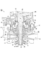
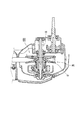
第1実施形態に係る鞍乗型車両用のベルト式無段変速機1001は、図2及び図3に示すように、プライマリ軸11と、プライマリシーブ12と、溝幅調節機構13と、ケース14と、セカンダリ軸15と、セカンダリシーブ16と、Vベルト17を備えている。
As shown in FIGS. 2 and 3, a belt type continuously
この鞍乗型車両用のベルト式無段変速機1001は、プライマリシーブ12及びセカンダリシーブ16のV溝にVベルト17が巻掛けられており、プライマリシーブ12及びセカンダリシーブ16の溝幅を変えることによって、変速比を無段階に制御する。
In the belt type continuously
詳しくは、プライマリ軸11は、図2に示すように、クランク部30と、クランク部30より片側に延在し、プライマリシーブ12が装着された延在部32を備えている。この実施形態では、プライマリ軸11は、エンジン33に取り付けられたクランクシャフトであり、略中央部にクランク部30が設けられている。クランク部30は、クランクジャーナル41と、クランクウエブ42と、クランクピン43と、コンロッド44と、ピストン45を構成する各部材が連結されている。このプライマリ軸11は、クランク部30から両側に延在している。両側の延在部32、34はそれぞれケース14に回転可能に支持されている。
Specifically, as shown in FIG. 2, the primary shaft 11 includes a
プライマリシーブ12及び溝幅調節機構13は、プライマリ軸11の図2中の左側に延在した延在部32にそれぞれ装着されている。当該延在部32にはスプライン32aが形成されており、端部には後述するロックナット74を取り付けるための雄ねじ32bが形成されている。
The
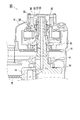
プライマリシーブ12は、図4に拡大して示すように、固定フランジ51と、可動フランジ52で構成されている。固定フランジ51は延在部32の先端側に固定的に配設されており、可動フランジ52は延在部32の基端側にプライマリ軸11に対して軸方向に移動可能に配設されている。この実施形態では、プライマリシーブ12の固定フランジ51と可動フランジ52は、それぞれ略円盤状の部材であり、軸方向で対向する面がそれぞれ円錐面51a、52aで形成されている。固定フランジ51と可動フランジ52とは、互いの円錐面51a、52aを対向させることにより、相互間にVベルト17が巻き掛けられるV溝を形成している。
As shown in an enlarged view in FIG. 4, the
固定フランジ51の中央部には、プライマリ軸11に挿通される挿通穴55が形成されており、斯かる挿通穴55の内周面にはプライマリ軸11のスプラインに応じたスプラインが形成されている。また、可動フランジ52の中央部には、後述する溝幅調節機構13に取り付けるための取付部56が形成されている。
An
溝幅調節機構13は、図4に示すように、可動フランジ52を軸方向に移動させることによってプライマリシーブ12の溝幅を調節する機構である。この実施形態では、溝幅調節機構13は、スライダ61と、送り部材62と、ガイド部材63と、歯車64と、固定側支持部材65とで構成されている。
As shown in FIG. 4, the groove
このベルト式無段変速機1001は、プライマリシーブ12及び溝幅調節機構13をプライマリ軸11に取り付ける部材として、回転側支持部材71と、第1スリーブ72と、第2スリーブ73と、ロックナット74を備えている。
The belt type continuously
ケース14は、図2に示すように、プライマリシーブ12と溝幅調節機構13を覆い、一部がクランクウエブ42に近接している。また、ケース14は、プライマリシーブ12の固定フランジ51側においてプライマリ軸11を回転可能に支持するとともに、プライマリシーブ12の可動フランジ52側において溝幅調節機構13を支持している。この実施形態では、ケース14は、複数の部材を接合したものであり、全体としてプライマリ軸11、プライマリシーブ12、溝幅調節機構13を覆っている。そして、ケース14の一部は、上述したプライマリ軸11のクランクウエブ42に近接した位置に延在している。
As shown in FIG. 2, the
この実施形態に係るベルト式無段変速機1001では、固定フランジ51は、図4に示すように、回転側支持部材71、第1スリーブ72、固定フランジ51、第2スリーブ73、ロックナット74の順でプライマリ軸11に装着されている。第1スリーブ72と固定フランジ51は、それぞれプライマリ軸11のスプライン32aに噛み合った状態で装着されており、プライマリ軸11と一緒に回転する。第2スリーブ73は、プライマリ軸11に装着した部材であり、一端を固定フランジ51に当接させており、プライマリ軸11の端部に形成された雄ねじ32bに螺合させたロックナット74によってプライマリ軸11から抜けないようになっている。プライマリ軸11の端部は、第2スリーブ73とケース14との間に装着した軸受75によって、回転可能に支持されている。
In the belt type continuously
第1スリーブ72は軸方向に沿って配設されたガイド機構76を備えている。溝幅調節機構13のスライダ61はガイド機構76によって軸方向に沿って移動するように第1スリーブ72に装着されている。可動フランジ52はスライダ61に取り付けられている。スライダ61には、軸受77を介して送り部材62と歯車64が取り付けられている。歯車64にはモータ81の出力が入力される。また、送り部材62の外周面には雄ねじ62aが形成されており、ケース14に固定的に配設されたガイド部材63の内周面に形成された雌ねじ63aに噛み合わせている。
The
溝幅調節機構13のガイド部材63は、プライマリ軸11に装着された回転側支持部材71に軸受78を介して取り付けられ、かつ、ケース14に固定的に配設された固定側支持部材65に取り付けられている。これにより、ガイド部材63は、プライマリ軸11の回転にかかわらず、ケース14に対して固定的に配設されている。なお、この実施形態では、軸受78は、固定側支持部材65と回転側支持部材71との間に、軸方向に摺動可能に装着されている。回転側支持部材71はプライマリ軸11に固定されており、固定側支持部材65はケース14に対して固定されている。プライマリ軸11がケース14に対して軸方向に相対的に移動すると、これに応じて回転側支持部材71が固定側支持部材65に対して軸方向に相対移動する。
The
この溝幅調節機構13によって、可動フランジ52は、モータ81の回転、及び、送り部材62とガイド部材63との噛み合いに応じて、スライダ61とともに軸方向に移動する。
By this groove
プライマリシーブ12の固定フランジ51と可動フランジ52により形成されるV溝には、Vベルト17が巻き掛けられている。Vベルト17は、図3に示すように、セカンダリ軸15に装着されたセカンダリシーブ16に巻き掛けられている。セカンダリシーブ16の溝幅は、可動フランジ52に装着されたばねによって、プライマリシーブ12の溝幅の変化に応じた溝幅に調整される。すなわち、プライマリシーブ12の溝幅は、制御装置82によって制御されるモータ81の回転に応じて変化し、図2、図3に示すように、プライマリシーブ12の溝幅が狭い場合には、セカンダリシーブ16の溝幅が広くなる。反対に、図5、図6に示すように、プライマリシーブ12の溝幅が広くなるとセカンダリシーブ16の溝幅が狭くなる。
The
この実施形態では、図4に示すように、クランクウエブ42とケース14が近接する部位Sにおいて、Vベルト17に作用する張力によりプライマリシーブ12に作用する軸方向荷重によって、ケース14がプライマリ軸11に対して動く移動量(移動距離)よりも、Vベルト17に張力が作用していない状態でのクランクウエブ42とケース14との隙間の方を広くしている。
In this embodiment, as shown in FIG. 4, in a region S where the
このベルト式無段変速機1001は、Vベルト17の張力を受けて、プライマリシーブ12の固定フランジ51と可動フランジ52を軸方向に離す方向に力が作用する。この実施形態では、固定フランジ51に作用する軸方向荷重Aは、第2スリーブ73とロックナット74を介してプライマリ軸11を、図4中の左へ移動させるように作用する。これに対し、可動フランジ52に作用する軸方向荷重Bは、スライダ61、軸受77、送り部材62、ガイド部材63、固定側支持部材65を介して、ケース14のクランクウエブ42に近接する部分に伝わり、クランクウエブ42に近接する部分において、ケース14を図4中の右へ移動させるように作用する。
The belt type continuously
このためVベルト17の張力を受けて、プライマリシーブ12の固定フランジ51と可動フランジ52を軸方向に離す方向に力が作用すると、プライマリ軸11のクランクウエブ42とケース14が近接する部位Sにおいて、クランクウエブ42が左に移動し、ケース14が右に移動して、両者の距離が近くなる。
For this reason, when a force acts in the direction of separating the fixed
この実施形態では、クランクウエブ42とケース14が近接する部位Sにおいて、Vベルト17に作用する張力によりプライマリシーブ12に作用する軸方向荷重によって、ケース14がプライマリ軸11に対して動く移動量よりも、ケース14とクランクウエブ42との隙間Sを広くしているので、ケース14とクランクウエブ42とが接触せず、クランクウエブ42とケース14が近接する部位Sに磨耗が生じるのを防止することができる。
In this embodiment, in the region S where the
これにより、ベルト式無段変速機1001において、斯かる部位Sの磨耗に起因する不具合の発生を防止することができる。
Thereby, in the belt-type continuously
次に、本発明の第2実施形態を説明する。 Next, a second embodiment of the present invention will be described.
本発明の第2実施形態に係る鞍乗型車両用のベルト式無段変速機1002は、図7に示すように、プライマリ軸11に装着され、プライマリシーブ12の固定フランジ51に当接した第2スリーブ73と、第2スリーブ73とケース14との間に装着され、外輪がケース14に固定された軸受75とを備えている。
A belt type continuously
第2スリーブ73は、プライマリ軸11に装着され、プライマリシーブ12の固定フランジ51に当接している。軸受75は、内輪を第2スリーブ73に装着し、外輪をケース14に装着し、ケース14の内周面にサークリップ91を取り付けてケース14に固定している。
The
詳しくは、図7に示す例では、第2スリーブ73の外周面には図7中の右端部にフランジ73aが形成されており、軸受75を第2スリーブ73に装着するとともに、このフランジ73aに当接させている。さらに、ケース14の軸受75を装着する部分には、軸受75を装着する方向の奥側に、軸受75を着座させる受け部92を備えている。そして、ケース14に軸受75を装着した状態で、サークリップ91で軸受75をケース14に固定している。
Specifically, in the example shown in FIG. 7, a
この実施形態によれば、図7に示すように、プライマリシーブ12の固定フランジ51に作用した力Aは、第2スリーブ73のフランジ部73a、軸受75、サークリップ91を介してケース14に力が伝わる。これに対して、可動フランジ52に作用した力Bは、スライダ61、軸受77、送り部材62、ガイド部材63、固定側支持部材65を介して、ケース14に伝わる。このように、固定フランジ51に作用した力Aと、可動フランジ52に作用した力Bは、いずれもケース14に伝わり、ケース14によって支持される。この際、ケース14には微小な弾性変形が生じることも考えられる。この実施形態では、斯かる弾性変形によってケース14がクランクウエブ42に近づく距離よりも、ケース14とクランクウエブ42との隙間Sを広くしている。このため、ケース14とクランクウエブ42とが接触せず、クランクウエブ42とケース14が近接する部位Sに磨耗が生じるのを防止することができる。
According to this embodiment, as shown in FIG. 7, the force A acting on the fixing
次に、本発明の第3実施形態を説明する。 Next, a third embodiment of the present invention will be described.
本発明の第3実施形態に係る鞍乗型車両用のベルト式無段変速機1003は、図8に示すように、プライマリシーブ12が装着された側とは反対側にクランク部30から延在した延在部34に、プライマリ軸11がケース14に対してプライマリシーブ12が装着された側に移動するのを規制する移動規制手段100を備えたものである。
As shown in FIG. 8, a belt type continuously
この場合、プライマリシーブ12が装着された側とは反対側にクランク部30から延在した延在部34に、プライマリ軸11がケース14に対してプライマリシーブ12が装着された側に移動するのを規制する移動規制手段100によって、プライマリ軸11が左へ動く移動量を小さく抑えることができる。これにより、クランクウエブ42とケース14が近接する部位Sにおいて、ケース14とクランクウエブ42とが接触し難くなり、クランクウエブ42とケース14が近接する部位Sに磨耗が生じるのをより確実に防止することができる。なお、クランクウエブ42とケース14が近接する部位Sについては図2参照。
In this case, the primary shaft 11 moves to the side where the
図8に示す実施形態では、移動規制手段100は、プライマリシーブ12が装着された側とは反対側にクランク部30から延在した延在部34において、プライマリ軸11とケース14との間に装着した軸受101を備え、軸受101をプライマリ軸11及びケース14に係合させた構造を採用している。
In the embodiment shown in FIG. 8, the movement restricting means 100 is provided between the primary shaft 11 and the
詳しくは、プライマリ軸11には、スリーブ104が装着されており、軸受101は、このスリーブ104とケース14との間に装着されている。プライマリ軸11の軸端には、ロックナット105が装着されてスリーブ104の抜け止めが施されている。そして、ケース14の内周面によって、軸受101の外輪がケース14に対して図8中の左へ移動するのを規制している。さらに、スリーブ104に取り付けられたサークリップ103によって、軸受101の内輪がスリーブ104に対して図8中の右へ移動するのを規制している。なお、この実施形態では、ケース14は、プライマリ軸11にスリーブ104、軸受101、ロックナット105等を取り付けることができるように、ケース14の図8中の右側面を別部材106で構成し、当該別部材106をボルト107で取り付けている。
Specifically, a
この実施形態によれば、図8に示すように、プライマリシーブ12が装着された側とは反対側に延在した延在部34において、サークリップ103によって、軸受101がプライマリ軸11及びケース14に係合し、プライマリ軸11がケース14に対してプライマリシーブ12が装着された側(図8中の左側)に移動するのが規制されている。これにより、プライマリ軸11が左へ動く移動量を小さく抑えることができ、クランクウエブ42とケース14が近接する部位Sにおいて、ケース14とクランクウエブ42とが接触し難くなり、クランクウエブ42とケース14が近接する部位Sに磨耗が生じるのをより確実に防止することができる。クランクウエブ42とケース14が近接する部位Sについては図2参照。
According to this embodiment, as shown in FIG. 8, the
以上、プライマリシーブ12が装着された側とは反対側にクランク部30から延在した延在部34に、プライマリ軸11がケース14に対してプライマリシーブ12が装着された側に移動するのを規制する移動規制手段100を例示したが、移動規制手段100は、上記の実施形態に限定されるものではない。
As described above, the primary shaft 11 moves to the side where the
次に、本発明の第4実施形態を説明する。 Next, a fourth embodiment of the present invention will be described.
本発明の第4実施形態に係る鞍乗型車両用のベルト式無段変速機1004は、図9に示すように、クランクウエブ42とケース14が近接する部位Sにおいて、クランクウエブ42にケース14が接触して磨耗することを防止する磨耗防止手段200を備えている。
As shown in FIG. 9, the belt type continuously
磨耗防止手段200として、この実施形態では、クランクウエブ42とケース14との間にスラストワッシャ201を取り付けている。
In this embodiment, a
この実施形態によれば、クランクウエブ42とケース14が近接する部位Sにおいて、ケース14とクランクウエブ42とが直接接触することなく、スラストワッシャ201が介在していることにより、クランクウエブ42とケース14が近接する部位Sに生じる磨耗を不具合が生じない程度に緩和させることができる。
According to this embodiment, in the part S where the
スラストワッシャ201としては、クランクウエブ42とケース14との間にワッシャを介在させるとよいが、ワッシャは、1枚だけでなく、複数枚取り付けてもよい。
As the
なお、磨耗防止手段200としては、スラストワッシャ201に代えて、クランクウエブ42とケース14との間にスラスト軸受を取り付けてもよい。この場合、クランクウエブ42とケース14との間に軸方向に作用する力をスラスト軸受で受けることができるから、クランクウエブ42とケース14が接触することがなく、クランクウエブ42とケース14に近接する部位Sに磨耗が生じるのを確実に防止することができる。
As the
次に、本発明の第5実施形態を説明する。 Next, a fifth embodiment of the present invention will be described.
本発明の第5実施形態に係る鞍乗型車両用のベルト式無段変速機1005は、図10に示すように、上述した磨耗防止手段200として、クランクウエブ42とケース14が近接する部位Sにおいて、プライマリ軸11とケース14との間に軸受202を取り付けたものである。
As shown in FIG. 10, a belt type continuously
この実施形態によれば、クランクウエブ42とケース14が近接する部位Sにおいて、プライマリ軸11とケース14との間に軸受202を取り付けており、ケース14とプライマリ軸11との相対的な位置関係を軸受202によって規制することができる。このため、クランクウエブ42とケース14との接触を確実に防止でき、クランクウエブ42とケース14に近接する部位Sに磨耗が生じるのを確実に防止することができる。斯かる軸受202には、例えば、ボールベアリングを採用するとよく、さらに好ましくはスラスト方向に作用する力に対応できるアンギュラコンタクトラジアル軸受を用いるとよい。
According to this embodiment, the
以上、クランクウエブ42とケース14が近接する部位Sにおいて、クランクウエブ42にケース14が接触して磨耗することを防止する磨耗防止手段200を例示したが、磨耗防止手段200は上述した実施形態に限定されるものではない。
As described above, the wear prevention means 200 for preventing the
以上、本発明の一実施形態に係る鞍乗型車両用のベルト式無段変速機を説明したが、本発明に係る鞍乗型車両用のベルト式無段変速機は上記の実施形態に限定されるものではない。 The belt type continuously variable transmission for a saddle type vehicle according to one embodiment of the present invention has been described above. However, the belt type continuously variable transmission for a saddle type vehicle according to the present invention is limited to the above embodiment. Is not to be done.
本発明は、上述した実施形態に係る鞍乗型車両用のベルト式無段変速機に限らず、種々の構成部材が異なるものであっても、同様に、ケースと、プライマリ軸のクランクウエブの側面との近接部位に接触や、磨耗が生じることに起因する課題を有する場合において、広く適応できる。 The present invention is not limited to the belt type continuously variable transmission for the saddle riding type vehicle according to the above-described embodiment, and similarly, the case and the crank shaft of the primary shaft are different even if various components are different. In the case where there is a problem caused by contact or wear occurring in the vicinity of the side surface, it can be widely applied.
例えば、図7に示す、第2スリーブ73を、プライマリ軸11に装着し、プライマリシーブ12の固定フランジ51に当接させ、第2スリーブ73とケース14との間に装着した軸受75の外輪がケース14に固定した構造と、図8に示す、プライマリシーブ12が装着された側とは反対側にクランク部30から延在した延在部34に、プライマリ軸11がケース14に対してプライマリシーブ12が装着された側に移動するのを規制する移動規制手段100を備えた構造とは、組み合わせることができる。
For example, the outer sleeve of the
これにより両構造は、ともに、クランクウエブ42とケース14が近接する部位Sにおいて、クランクウエブ42がケース14に近づくように、プライマリ軸11が動くのを小さく抑える構造である。両構造を組み合わせると、両構造は協働してクランクウエブ42とケース14が近接する部位Sにおいて、クランクウエブ42がケース14に近づくように、プライマリ軸11が動くのをより確実に小さく抑えることができる。
Thus, both structures are structures that suppress the movement of the primary shaft 11 so that the
さらに、斯かる図7、図8に示す両構造は、それぞれ上述した磨耗防止手段を組み合わせることができる。この場合、図7、図8に示す両構造が、クランクウエブ42とケース14が近接する部位Sにおいて、クランクウエブ42がケース14に近づくように、プライマリ軸11が動くのを小さく抑える構造であるから、クランクウエブ42とケース14が近接する部位Sに配設される磨耗防止手段200(例えば、スラストワッシャ、スラスト軸受、ラジアル軸受)をより適切に機能させることができ、クランクウエブ42とケース14に近接する部位Sに磨耗が生じるのを確実に防止するだけでなく、ベルト式無段変速機の動作がよりスムーズになり、異音などの発生もより効果的に低減する。
Furthermore, both the structures shown in FIGS. 7 and 8 can be combined with the above-described wear prevention means. In this case, both structures shown in FIGS. 7 and 8 are structures that suppress the movement of the primary shaft 11 so that the
また、プライマリ軸とケースとの間に装着した軸受を、スリーブやサークリップによって、プライマリ軸やケースに係合させた構造を例示したが、軸受をプライマリ軸やケースに係合させる構造なども、他の構造を採用することができる。 Further, the structure in which the bearing mounted between the primary shaft and the case is engaged with the primary shaft or the case by the sleeve or the circlip, but the structure for engaging the bearing with the primary shaft or the case, etc. Other structures can be employed.
以上のとおり、本発明に係るベルト式無段変速機は、鞍乗型車両用のベルト式無段変速機として広く利用可能である。 As described above, the belt-type continuously variable transmission according to the present invention can be widely used as a belt-type continuously variable transmission for a straddle-type vehicle.
11 プライマリ軸
12 プライマリシーブ
13 溝幅調節機構
14 ケース
15 セカンダリ軸
16 セカンダリシーブ
17 Vベルト
30 クランク部
32 延在部
32a スプライン
33 エンジン
34 延在部
41 クランクジャーナル
41a すべり軸受
42 クランクウエブ
43 クランクピン
44 コンロッド
45 ピストン
51 固定フランジ
52 可動フランジ
55 挿通穴
56 取付部
61 スライダ
62 送り部材
63 ガイド部材
64 歯車
65 固定側支持部材
71 回転側支持部材
72 第1スリーブ
73 第2スリーブ
73a フランジ
74 ロックナット
75 軸受
76 ガイド機構
77 軸受
78 軸受
81 モータ
82 制御装置
91 サークリップ
92 受け部
100 移動規制手段
101 軸受
103 係合部材(サークリップ)
200 磨耗防止手段
201 スラストワッシャ
202 軸受
1000 ベルト式無段変速機
1001 第1実施形態に係るベルト式無段変速機
1002 第2実施形態に係るベルト式無段変速機
1003 第3実施形態に係るベルト式無段変速機
1004 第4実施形態に係るベルト式無段変速機
1005 第5実施形態に係るベルト式無段変速機
A 軸方向荷重
B 軸方向荷重
S クランクウエブとケースが近接する部位
11
200
Claims (7)
クランクウエブを備えたクランク部と、前記クランク部より片側に延在し、前記プライマリシーブが装着された延在部とを備えたプライマリ軸と、
前記延在部の先端側に固定的に配設された固定フランジと、前記延在部の基端側にプライマリ軸に対して軸方向に移動可能に配設された可動フランジとからなるプライマリシーブと、
前記可動フランジを軸方向に移動させることによってプライマリシーブの溝幅を調節する溝幅調節機構と、
前記プライマリシーブと溝幅調節機構を覆い、一部が前記クランクウエブに近接したケースとを備え、
前記ケースは、プライマリシーブの固定フランジ側においてプライマリ軸を回転可能に支持するとともに、前記プライマリシーブの可動フランジ側において溝幅調節機構を支持し、
前記クランクウエブとケースが近接する部位において、前記Vベルトに作用する張力によりプライマリシーブに作用する軸方向荷重によって、ケースがプライマリ軸に対して動く移動量よりも、前記Vベルトに張力が作用していない状態での前記クランクウエブとケースとの隙間が広く、
前記プライマリシーブが装着された側とは反対側に前記クランク部から延在した延在部に、前記プライマリ軸が、ケースに対してプライマリシーブが装着された側に移動するのを規制する移動規制手段を備えたことを特徴とする鞍乗型車両用のベルト式無段変速機。 A belt type continuously variable belt for a straddle type vehicle in which a V belt is wound around a V groove of a primary sheave and a secondary sheave, and a gear ratio is continuously controlled by changing a groove width of the primary sheave and the secondary sheave. A transmission,
A primary shaft comprising a crank portion provided with a crank web, and an extending portion that extends to one side from the crank portion and is fitted with the primary sheave;
A primary sheave comprising a fixed flange fixedly disposed on the distal end side of the extending portion and a movable flange disposed on the proximal end side of the extending portion so as to be movable in the axial direction with respect to the primary shaft. When,
A groove width adjusting mechanism for adjusting the groove width of the primary sheave by moving the movable flange in the axial direction;
Covering the primary sheave and the groove width adjusting mechanism, a part of which is close to the crank web,
The case supports the primary shaft rotatably on the fixed flange side of the primary sheave and supports the groove width adjusting mechanism on the movable flange side of the primary sheave,
In the region where the crank web and the case are close to each other, the axial load acting on the primary sheave due to the tension acting on the V-belt causes the tension to act on the V-belt rather than the amount of movement of the case relative to the primary shaft. the gap between the crank web and the case in the non state is widely,
Movement restriction that restricts movement of the primary shaft to the side where the primary sheave is mounted with respect to the case in an extending portion extending from the crank portion on the side opposite to the side where the primary sheave is mounted A belt-type continuously variable transmission for a saddle-ride type vehicle characterized by comprising means .
前記スリーブとケースとの間に装着され、外輪がケースに固定された軸受と
を備えた請求項1に記載の鞍乗型車両用のベルト式無段変速機。 A sleeve mounted on the primary shaft and in contact with a fixed flange of the primary sheave;
The belt type continuously variable transmission for a straddle-type vehicle according to claim 1, further comprising: a bearing mounted between the sleeve and the case, and an outer ring fixed to the case.
A straddle-type vehicle equipped with the belt-type continuously variable transmission for a straddle-type vehicle according to any one of claims 1 to 6 .
Priority Applications (6)
| Application Number | Priority Date | Filing Date | Title |
|---|---|---|---|
| JP2006260952A JP4819633B2 (en) | 2006-09-26 | 2006-09-26 | Belt type continuously variable transmission for saddle riding type vehicle and saddle riding type vehicle |
| TW096131270A TWI331662B (en) | 2006-09-26 | 2007-08-23 | Belt type continuously variable transmission for straddle-type vehicles and straddle-type vehicle |
| AT07253741T ATE549546T1 (en) | 2006-09-26 | 2007-09-21 | CONTINUOUSLY VARIABLE TRANSMISSION OVER A TAPE |
| EP07253741A EP1908994B1 (en) | 2006-09-26 | 2007-09-21 | Belt type continuously variable transmission |
| CN201210008277.XA CN102518763B (en) | 2006-09-26 | 2007-09-26 | For variable v-belt drive and the Straddle-type vehicle of Straddle-type vehicle |
| CN2007101520022A CN101153648B (en) | 2006-09-26 | 2007-09-26 | Belt type continuously variable transmission |
Applications Claiming Priority (1)
| Application Number | Priority Date | Filing Date | Title |
|---|---|---|---|
| JP2006260952A JP4819633B2 (en) | 2006-09-26 | 2006-09-26 | Belt type continuously variable transmission for saddle riding type vehicle and saddle riding type vehicle |
Related Child Applications (1)
| Application Number | Title | Priority Date | Filing Date |
|---|---|---|---|
| JP2011134824A Division JP5209759B2 (en) | 2011-06-17 | 2011-06-17 | Belt type continuously variable transmission for saddle riding type vehicle and saddle riding type vehicle |
Publications (2)
| Publication Number | Publication Date |
|---|---|
| JP2008082390A JP2008082390A (en) | 2008-04-10 |
| JP4819633B2 true JP4819633B2 (en) | 2011-11-24 |
Family
ID=38926380
Family Applications (1)
| Application Number | Title | Priority Date | Filing Date |
|---|---|---|---|
| JP2006260952A Active JP4819633B2 (en) | 2006-09-26 | 2006-09-26 | Belt type continuously variable transmission for saddle riding type vehicle and saddle riding type vehicle |
Country Status (5)
| Country | Link |
|---|---|
| EP (1) | EP1908994B1 (en) |
| JP (1) | JP4819633B2 (en) |
| CN (2) | CN102518763B (en) |
| AT (1) | ATE549546T1 (en) |
| TW (1) | TWI331662B (en) |
Families Citing this family (3)
| Publication number | Priority date | Publication date | Assignee | Title |
|---|---|---|---|---|
| US8449424B2 (en) | 2011-03-17 | 2013-05-28 | Fairfield Manufacturing Company Inc. | Integral electric motor with speed sensor, planetary gearbox and steering means |
| JP5945527B2 (en) * | 2013-10-23 | 2016-07-05 | ジヤトコ株式会社 | Continuously variable transmission and control method of continuously variable transmission |
| JP5876188B1 (en) * | 2015-01-14 | 2016-03-02 | ヤマハ発動機株式会社 | Engine system and saddle riding type vehicle |
Family Cites Families (12)
| Publication number | Priority date | Publication date | Assignee | Title |
|---|---|---|---|---|
| JP2699067B2 (en) | 1986-01-29 | 1998-01-19 | ヤマハ発動機株式会社 | Control device for friction type continuously variable transmission for vehicles |
| JP2950957B2 (en) | 1990-09-20 | 1999-09-20 | ヤマハ発動機株式会社 | Continuously variable transmission for motorcycles |
| JP3043061B2 (en) | 1990-11-30 | 2000-05-22 | ヤマハ発動機株式会社 | V-belt type automatic transmission for motorcycles |
| JP2002019682A (en) * | 2000-07-05 | 2002-01-23 | Yamaha Motor Co Ltd | Power transmission of engine for motorcycle |
| JP2003301903A (en) * | 2002-04-08 | 2003-10-24 | Yamaha Motor Co Ltd | Engine |
| DE60328594D1 (en) * | 2002-04-08 | 2009-09-10 | Yamaha Motor Co Ltd | Motor |
| JP2005036855A (en) * | 2003-07-18 | 2005-02-10 | Toyota Motor Corp | Belt-type continuously variable transmission |
| US7237638B2 (en) * | 2003-09-30 | 2007-07-03 | Honda Motor Co., Ltd. | V-belt type continuously variable transmission |
| JP4014555B2 (en) * | 2003-09-30 | 2007-11-28 | 本田技研工業株式会社 | V belt type continuously variable transmission |
| JP4523323B2 (en) * | 2004-04-20 | 2010-08-11 | 本田技研工業株式会社 | Soundproof structure in power unit |
| CN100523550C (en) * | 2004-06-28 | 2009-08-05 | 雅马哈发动机株式会社 | Belt type continuously variable transmission for saddle-riding type vehicle and saddle-riding type vehicle |
| CN100356045C (en) * | 2004-07-12 | 2007-12-19 | 雅马哈发动机株式会社 | Power transmission unit |
-
2006
- 2006-09-26 JP JP2006260952A patent/JP4819633B2/en active Active
-
2007
- 2007-08-23 TW TW096131270A patent/TWI331662B/en active
- 2007-09-21 EP EP07253741A patent/EP1908994B1/en active Active
- 2007-09-21 AT AT07253741T patent/ATE549546T1/en active
- 2007-09-26 CN CN201210008277.XA patent/CN102518763B/en active Active
- 2007-09-26 CN CN2007101520022A patent/CN101153648B/en active Active
Also Published As
| Publication number | Publication date |
|---|---|
| CN102518763B (en) | 2015-11-25 |
| EP1908994A1 (en) | 2008-04-09 |
| EP1908994B1 (en) | 2012-03-14 |
| TW200831806A (en) | 2008-08-01 |
| CN101153648A (en) | 2008-04-02 |
| TWI331662B (en) | 2010-10-11 |
| CN102518763A (en) | 2012-06-27 |
| JP2008082390A (en) | 2008-04-10 |
| ATE549546T1 (en) | 2012-03-15 |
| CN101153648B (en) | 2012-10-24 |
Similar Documents
| Publication | Publication Date | Title |
|---|---|---|
| US20080312013A1 (en) | Belt Continuously Variable Transmission for Straddle Type Vehicle, and Straddle Type Vehicle | |
| WO2005090828A1 (en) | Belt type continuously variable transmission, power unit having belt type continuously variable transmission, vehicle carrying belt type continuously variable transmission, and sheave for continuously variable transmission | |
| JP4819633B2 (en) | Belt type continuously variable transmission for saddle riding type vehicle and saddle riding type vehicle | |
| US20230279937A1 (en) | Continuously variable transmission for recreational vehicles and related components | |
| EP1691108B1 (en) | Metal belt | |
| JP5209759B2 (en) | Belt type continuously variable transmission for saddle riding type vehicle and saddle riding type vehicle | |
| US6334826B1 (en) | V belt type automatic transmission | |
| JP6108321B2 (en) | Belt type continuously variable transmission | |
| CA2403065C (en) | Drive ring cvt belt | |
| CN101828048A (en) | Shaft of belt-type continuously variable transmission, stationary sheave half for continuously variable transmission, method for production thereof, and continuously variable transmission | |
| JP4783694B2 (en) | Tension adjusting device and belt-driven bicycle | |
| JP2006017133A (en) | Bearing device | |
| WO2018051741A1 (en) | Belt-type stepless transmission | |
| JP5556730B2 (en) | Belt type continuously variable transmission | |
| JP3195868B2 (en) | Variable speed pulley device | |
| US9528591B2 (en) | Vehicle transmission | |
| JP2005163850A (en) | Continuously variable transmission | |
| JP2007032704A (en) | Auto tensioner | |
| JP2005163851A (en) | Continuously variable transmission | |
| JP2003120758A (en) | Belt for continuously variable transmission | |
| JP2005140235A (en) | Metal belt type continuously variable transmission | |
| JP2009103155A (en) | Power transmission chain and power transmission device | |
| JP2007100763A (en) | V-belt automatic transmission | |
| JP2002250416A (en) | Vehicle-mounted v-belt speed variable change gear | |
| JPH0547594U (en) | Belt type continuously variable transmission |
Legal Events
| Date | Code | Title | Description |
|---|---|---|---|
| A621 | Written request for application examination |
Free format text: JAPANESE INTERMEDIATE CODE: A621 Effective date: 20090803 |
|
| A131 | Notification of reasons for refusal |
Free format text: JAPANESE INTERMEDIATE CODE: A131 Effective date: 20110421 |
|
| A977 | Report on retrieval |
Free format text: JAPANESE INTERMEDIATE CODE: A971007 Effective date: 20110428 |
|
| A521 | Request for written amendment filed |
Free format text: JAPANESE INTERMEDIATE CODE: A523 Effective date: 20110617 |
|
| TRDD | Decision of grant or rejection written | ||
| A01 | Written decision to grant a patent or to grant a registration (utility model) |
Free format text: JAPANESE INTERMEDIATE CODE: A01 Effective date: 20110818 |
|
| A01 | Written decision to grant a patent or to grant a registration (utility model) |
Free format text: JAPANESE INTERMEDIATE CODE: A01 |
|
| A61 | First payment of annual fees (during grant procedure) |
Free format text: JAPANESE INTERMEDIATE CODE: A61 Effective date: 20110901 |
|
| FPAY | Renewal fee payment (event date is renewal date of database) |
Free format text: PAYMENT UNTIL: 20140909 Year of fee payment: 3 |
|
| R150 | Certificate of patent or registration of utility model |
Ref document number: 4819633 Country of ref document: JP Free format text: JAPANESE INTERMEDIATE CODE: R150 Free format text: JAPANESE INTERMEDIATE CODE: R150 |
|
| R250 | Receipt of annual fees |
Free format text: JAPANESE INTERMEDIATE CODE: R250 |
|
| R250 | Receipt of annual fees |
Free format text: JAPANESE INTERMEDIATE CODE: R250 |
|
| R250 | Receipt of annual fees |
Free format text: JAPANESE INTERMEDIATE CODE: R250 |
|
| R250 | Receipt of annual fees |
Free format text: JAPANESE INTERMEDIATE CODE: R250 |
|
| R250 | Receipt of annual fees |
Free format text: JAPANESE INTERMEDIATE CODE: R250 |
|
| R250 | Receipt of annual fees |
Free format text: JAPANESE INTERMEDIATE CODE: R250 |
|
| R250 | Receipt of annual fees |
Free format text: JAPANESE INTERMEDIATE CODE: R250 |
|
| R250 | Receipt of annual fees |
Free format text: JAPANESE INTERMEDIATE CODE: R250 |
|
| R250 | Receipt of annual fees |
Free format text: JAPANESE INTERMEDIATE CODE: R250 |
|
| R250 | Receipt of annual fees |
Free format text: JAPANESE INTERMEDIATE CODE: R250 |