JP4819359B2 - Electro-hydraulic brake device and monitoring method thereof - Google Patents
Electro-hydraulic brake device and monitoring method thereof Download PDFInfo
- Publication number
- JP4819359B2 JP4819359B2 JP2004533350A JP2004533350A JP4819359B2 JP 4819359 B2 JP4819359 B2 JP 4819359B2 JP 2004533350 A JP2004533350 A JP 2004533350A JP 2004533350 A JP2004533350 A JP 2004533350A JP 4819359 B2 JP4819359 B2 JP 4819359B2
- Authority
- JP
- Japan
- Prior art keywords
- pump
- hydraulic
- electric motor
- discharge output
- brake device
- Prior art date
- Legal status (The legal status is an assumption and is not a legal conclusion. Google has not performed a legal analysis and makes no representation as to the accuracy of the status listed.)
- Expired - Fee Related
Links
Images


Classifications
-
- B—PERFORMING OPERATIONS; TRANSPORTING
- B60—VEHICLES IN GENERAL
- B60T—VEHICLE BRAKE CONTROL SYSTEMS OR PARTS THEREOF; BRAKE CONTROL SYSTEMS OR PARTS THEREOF, IN GENERAL; ARRANGEMENT OF BRAKING ELEMENTS ON VEHICLES IN GENERAL; PORTABLE DEVICES FOR PREVENTING UNWANTED MOVEMENT OF VEHICLES; VEHICLE MODIFICATIONS TO FACILITATE COOLING OF BRAKES
- B60T8/00—Arrangements for adjusting wheel-braking force to meet varying vehicular or ground-surface conditions, e.g. limiting or varying distribution of braking force
- B60T8/32—Arrangements for adjusting wheel-braking force to meet varying vehicular or ground-surface conditions, e.g. limiting or varying distribution of braking force responsive to a speed condition, e.g. acceleration or deceleration
- B60T8/34—Arrangements for adjusting wheel-braking force to meet varying vehicular or ground-surface conditions, e.g. limiting or varying distribution of braking force responsive to a speed condition, e.g. acceleration or deceleration having a fluid pressure regulator responsive to a speed condition
- B60T8/40—Arrangements for adjusting wheel-braking force to meet varying vehicular or ground-surface conditions, e.g. limiting or varying distribution of braking force responsive to a speed condition, e.g. acceleration or deceleration having a fluid pressure regulator responsive to a speed condition comprising an additional fluid circuit including fluid pressurising means for modifying the pressure of the braking fluid, e.g. including wheel driven pumps for detecting a speed condition, or pumps which are controlled by means independent of the braking system
- B60T8/4072—Systems in which a driver input signal is used as a control signal for the additional fluid circuit which is normally used for braking
- B60T8/4081—Systems with stroke simulating devices for driver input
-
- B—PERFORMING OPERATIONS; TRANSPORTING
- B60—VEHICLES IN GENERAL
- B60T—VEHICLE BRAKE CONTROL SYSTEMS OR PARTS THEREOF; BRAKE CONTROL SYSTEMS OR PARTS THEREOF, IN GENERAL; ARRANGEMENT OF BRAKING ELEMENTS ON VEHICLES IN GENERAL; PORTABLE DEVICES FOR PREVENTING UNWANTED MOVEMENT OF VEHICLES; VEHICLE MODIFICATIONS TO FACILITATE COOLING OF BRAKES
- B60T13/00—Transmitting braking action from initiating means to ultimate brake actuator with power assistance or drive; Brake systems incorporating such transmitting means, e.g. air-pressure brake systems
- B60T13/10—Transmitting braking action from initiating means to ultimate brake actuator with power assistance or drive; Brake systems incorporating such transmitting means, e.g. air-pressure brake systems with fluid assistance, drive, or release
- B60T13/12—Transmitting braking action from initiating means to ultimate brake actuator with power assistance or drive; Brake systems incorporating such transmitting means, e.g. air-pressure brake systems with fluid assistance, drive, or release the fluid being liquid
- B60T13/14—Transmitting braking action from initiating means to ultimate brake actuator with power assistance or drive; Brake systems incorporating such transmitting means, e.g. air-pressure brake systems with fluid assistance, drive, or release the fluid being liquid using accumulators or reservoirs fed by pumps
- B60T13/148—Arrangements for pressure supply
-
- B—PERFORMING OPERATIONS; TRANSPORTING
- B60—VEHICLES IN GENERAL
- B60T—VEHICLE BRAKE CONTROL SYSTEMS OR PARTS THEREOF; BRAKE CONTROL SYSTEMS OR PARTS THEREOF, IN GENERAL; ARRANGEMENT OF BRAKING ELEMENTS ON VEHICLES IN GENERAL; PORTABLE DEVICES FOR PREVENTING UNWANTED MOVEMENT OF VEHICLES; VEHICLE MODIFICATIONS TO FACILITATE COOLING OF BRAKES
- B60T17/00—Component parts, details, or accessories of power brake systems not covered by groups B60T8/00, B60T13/00 or B60T15/00, or presenting other characteristic features
- B60T17/18—Safety devices; Monitoring
- B60T17/22—Devices for monitoring or checking brake systems; Signal devices
- B60T17/221—Procedure or apparatus for checking or keeping in a correct functioning condition of brake systems
-
- B—PERFORMING OPERATIONS; TRANSPORTING
- B60—VEHICLES IN GENERAL
- B60T—VEHICLE BRAKE CONTROL SYSTEMS OR PARTS THEREOF; BRAKE CONTROL SYSTEMS OR PARTS THEREOF, IN GENERAL; ARRANGEMENT OF BRAKING ELEMENTS ON VEHICLES IN GENERAL; PORTABLE DEVICES FOR PREVENTING UNWANTED MOVEMENT OF VEHICLES; VEHICLE MODIFICATIONS TO FACILITATE COOLING OF BRAKES
- B60T8/00—Arrangements for adjusting wheel-braking force to meet varying vehicular or ground-surface conditions, e.g. limiting or varying distribution of braking force
- B60T8/32—Arrangements for adjusting wheel-braking force to meet varying vehicular or ground-surface conditions, e.g. limiting or varying distribution of braking force responsive to a speed condition, e.g. acceleration or deceleration
- B60T8/34—Arrangements for adjusting wheel-braking force to meet varying vehicular or ground-surface conditions, e.g. limiting or varying distribution of braking force responsive to a speed condition, e.g. acceleration or deceleration having a fluid pressure regulator responsive to a speed condition
- B60T8/40—Arrangements for adjusting wheel-braking force to meet varying vehicular or ground-surface conditions, e.g. limiting or varying distribution of braking force responsive to a speed condition, e.g. acceleration or deceleration having a fluid pressure regulator responsive to a speed condition comprising an additional fluid circuit including fluid pressurising means for modifying the pressure of the braking fluid, e.g. including wheel driven pumps for detecting a speed condition, or pumps which are controlled by means independent of the braking system
- B60T8/4036—Pump units characterised by their failure-responsive means
-
- B—PERFORMING OPERATIONS; TRANSPORTING
- B60—VEHICLES IN GENERAL
- B60T—VEHICLE BRAKE CONTROL SYSTEMS OR PARTS THEREOF; BRAKE CONTROL SYSTEMS OR PARTS THEREOF, IN GENERAL; ARRANGEMENT OF BRAKING ELEMENTS ON VEHICLES IN GENERAL; PORTABLE DEVICES FOR PREVENTING UNWANTED MOVEMENT OF VEHICLES; VEHICLE MODIFICATIONS TO FACILITATE COOLING OF BRAKES
- B60T8/00—Arrangements for adjusting wheel-braking force to meet varying vehicular or ground-surface conditions, e.g. limiting or varying distribution of braking force
- B60T8/32—Arrangements for adjusting wheel-braking force to meet varying vehicular or ground-surface conditions, e.g. limiting or varying distribution of braking force responsive to a speed condition, e.g. acceleration or deceleration
- B60T8/34—Arrangements for adjusting wheel-braking force to meet varying vehicular or ground-surface conditions, e.g. limiting or varying distribution of braking force responsive to a speed condition, e.g. acceleration or deceleration having a fluid pressure regulator responsive to a speed condition
- B60T8/40—Arrangements for adjusting wheel-braking force to meet varying vehicular or ground-surface conditions, e.g. limiting or varying distribution of braking force responsive to a speed condition, e.g. acceleration or deceleration having a fluid pressure regulator responsive to a speed condition comprising an additional fluid circuit including fluid pressurising means for modifying the pressure of the braking fluid, e.g. including wheel driven pumps for detecting a speed condition, or pumps which are controlled by means independent of the braking system
- B60T8/404—Control of the pump unit
Description
本発明は、液圧源が電子制御ユニットによって制御可能であり、液圧源が電動機によって駆動される液圧ポンプと、このポンプによって圧力を供給可能な高圧アキュムレータとによって形成されている、“ブレーキ−バイ−ワイヤ”のタイプの自動車用電気油圧式ブレーキ装置に関する。本発明は更に、この種の電気油圧式ブレーキ装置を監視する方法に関する。 According to the present invention, a “brake” is formed by a hydraulic pressure pump that can be controlled by an electronic control unit, the hydraulic pressure source being driven by an electric motor, and a high-pressure accumulator that can supply pressure by the pump. The present invention relates to an electrohydraulic brake device for vehicles of the “by-wire” type. The invention further relates to a method for monitoring such an electrohydraulic brake device.
特許文献1により、ブレーキ装置をチェックするための方法と装置が知られている。その際、圧力媒体に溶けていないガスまたは空気の量は、車輪ブレーキ内で上昇および低下した圧力の時間的な変化から、圧力媒体内のガス量を求めることによって決定される。その際、空気またはガスが液圧システム内に既に侵入しているときに初めて、空気またはガスの量が判定されることは不利であると見なされる。この公知の方法の他の欠点は、自動車の停止状態でしかブレーキシステムの検査を行うことができないことにある。
そこで、本発明の課題は、できるだけ早い時点で、例えばシステムへの空気またはガスの侵入時に既に、空気またはガスを判定することができる、冒頭に述べた種類の自動車ブレーキ装置を検査するための手段を提供することである。更に、ブレーキシステムの操作に依存しないでおよび自動車の運転中にブレーキシステムを検査できるようにすべきである。 The object of the present invention is therefore a means for inspecting a motor vehicle braking device of the kind mentioned at the beginning, which can already determine air or gas at the earliest possible time, for example when air or gas enters the system. Is to provide. Furthermore, it should be possible to inspect the brake system independently of the operation of the brake system and while driving the vehicle.
この課題は本発明に従い、ポンプの吸込み側のガス量または空気量を判定するためにポンプの油圧吐出出力を監視する手段が設けられていることによって解決される。 This problem is solved according to the present invention by providing means for monitoring the hydraulic discharge output of the pump to determine the amount of gas or air on the suction side of the pump.
発明思想を具体化するために、油圧吐出出力の監視が、液圧ポンプを駆動する電動機の起電力(電動力)を判定することによって行われる。 In order to embody the inventive concept, the hydraulic discharge output is monitored by determining the electromotive force (electric force) of the electric motor that drives the hydraulic pump.
有利な実施形では、油圧吐出出力の監視が、液圧ポンプを駆動する電動機の電力消費を判定することによって行われる。 In an advantageous embodiment, the hydraulic discharge output is monitored by determining the power consumption of the motor driving the hydraulic pump.
他の有利な実施形では、油圧吐出出力の監視が、液圧ポンプを駆動する電動機の回転速度を判定することによって行われる。 In another advantageous embodiment, the hydraulic discharge output is monitored by determining the rotational speed of the electric motor that drives the hydraulic pump.
低価格の有利な実施形では、回転速度がポンプを駆動する電動機の起電力から求められる。そのために、本発明に従い、電動機の動作周波数が好ましくは25Hzであり、低域フィルタの時定数が好ましくは4msecである。 In a low-cost advantageous embodiment, the rotational speed is determined from the electromotive force of the motor that drives the pump. Therefore, according to the present invention, the operating frequency of the motor is preferably 25 Hz, and the time constant of the low-pass filter is preferably 4 msec.
更に、課題は方法では、ポンプの吸込み側のガス量または空気量がポンプの油圧吐出出力の決定によって判定されることによって解決される。 Furthermore, the problem is solved in the method by determining the amount of gas or air on the suction side of the pump by determining the hydraulic discharge output of the pump.
本発明による方法の他の有利な特徴は従属請求項9〜14から明らかである。 Other advantageous features of the method according to the invention are apparent from the dependent claims 9-14.
添付の図を参照した実施の形態の次の記載において本発明による方法を詳しく説明する。 The method according to the invention will be described in detail in the following description of the embodiments with reference to the accompanying figures.
図1に概略的に示したブレーキ装置は実質的に、ブレーキペダル1によって操作可能な二系統型の油圧式圧力発生器またはタンデム構造のマスターシリンダ2と、タンデムマスターシリンダ2と協働する変位シミュレータ3と、タンデムマスターシリンダ2に付設された圧力媒体貯蔵容器4と、油圧式圧力源と、概略的に示した制御ユニットHCU6と、電子制御兼調整ユニットECU16とからなっている。この制御ユニットは特に、圧力調整のために必要なすべての要素を含み、この制御ユニットには、例えば自動車の後車軸に付設された車輪ブレーキ7,8が接続されている。示唆的に示した車輪センサ24,25は車輪の回転速度を測定する働きをする。それ自体公知のタンデムマスターシリンダ2は2個のピストン9,10によって画成された互いに分離された圧力室14,15を備えている。この圧力室は圧力媒体貯蔵容器4に接続可能であり、かつHCU6を介して車輪ブレーキ7,8に接続可能である。前述の圧力源は、電動機22とこの電動機22によって駆動されるポンプ23とからなるモータ−ポンプ−装置20と、ポンプに対して並列に接続された圧力制限弁26と、ポンプ23に圧力を加えることができる高圧アキュムレータ21とによって形成されている。高圧アキュムレータ21によって加えられる液圧は圧力センサ35によって監視される。
The brake device schematically shown in FIG. 1 is substantially a dual hydraulic pressure generator or
更に図1から明らかなように、車輪ブレーキ7,8は管路5によって第1の圧力室14に接続されている。この管路5には、分離弁11が装置されている。この分離弁は通電しないときに開放する(SO−)2/2方向制御弁として形成され、第1の圧力室14を遮断することができる。第2の液圧管路34はポンプ23の圧力側または高圧アキュムレータ21を、車輪ブレーキ7,8の手前に接続配置された2個の2/2方向制御弁または入口弁17,18の入口ポートに接続する。この入口弁は電磁操作可能で、アナログ制御可能で、好ましくは通電しないときに閉じる(SG−)。同様に電磁操作可能で、アナログ制御可能で、好ましくは通電しないときに閉じる(SG−)2/2方向制御弁または出口弁27,28は、車輪ブレーキ7,8を圧力媒体貯蔵容器4に接続することができる。一方、電磁操作可能で、好ましくは通電しないときに開放する(SO−)圧力補償弁13は、車輪ブレーキ7,8に加えられる圧力を車輪毎に調整することができる。
Further, as is clear from FIG. 1, the wheel brakes 7 and 8 are connected to the
更に、車輪ブレーキ7,8に圧力センサ30,31が付設されている。この圧力センサによって、車輪ブレーキ7,8内の液圧が測定される。前述の電子式調整兼制御ユニットECU16には、圧力センサ19,30,31,35と車輪回転速度センサ24,25と好ましくは冗長的に形成されマスターブレーキシリンダ2に付設されたブレーキング要求検出装置33との出力信号が供給される。この電子式調整兼制御ユニットはモータ−ポンプ−装置20と前述の弁11,13,17,18,27,28を制御する働きをする。
Furthermore,
前述のブレーキ装置(その運転は専門家に知られている)の液圧制御ユニットHCU6は、電動機22に供給される電圧の時間的な変化を検出するA/Dコンバータ32を備えている。電動機22は通常のごとく、例えば175Hzの比較的に高い周波数で作動させられる。A/Dコンバータ32の出力信号は電子式制御兼調整ユニット16に供給され、そこで評価される。申し分のない評価を行うことができるようにするために、A/Dコンバータ32の評価すべき出力信号をろ波しなければならない。なぜなら、整流時に生じる火花形成に基づいて強いノイズを生じるからである。そのために、ECU16は図示していない低域フィルタを備えている。この低域フィルタの時定数はいわゆる整流火花から生じ、好ましくは4msecである。その際、電動機22は前述の比較的に高い周波数ではなく、好ましくは25Hzの低い周波数で作動させられる。
The hydraulic control unit HCU6 of the aforementioned brake device (whose operation is known to experts) includes an A /
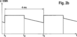
図2aに示したろ波した信号の変化から明らかなように、t1とt2の間の時間インターバルにおいて、電動機は一定の電圧で運転される。t2とt3の間の時間インターバルでは、電動機はジェネレータ運転を続け、起電力を発生する。区間t2−t3に示した起電力の変化は、電動機が負荷下で作動しかつ排他的に圧力媒体をシステムに供給するポンプ23を駆動するケースに相当する。これに対して、図2bには、t2−t3の区間における、電動機22の起電力の変化が示してある。この電動機は空気またはガスを吸い込むポンプ23を駆動する。空気またはガスの吸込みを確実に判定するために、起電力の現在の値をECU16に記憶された、所望な負荷運転を示す値と比較することにより、電動機は常に監視される。すなわち、自動車の連続運転でのポンプの吸込み側の監視が行われる。
Shows braze As is apparent from the change in the wave signal in Fig. 2a, the time interval between t 1 and t 2, the motor is operated at a constant voltage. The time interval between t 2 and t 3, the motor continues to generators operating, generates an electromotive force. The change in electromotive force shown in the section t 2 -t 3 corresponds to a case in which the motor operates under a load and drives the pump 23 that exclusively supplies the pressure medium to the system. On the other hand, FIG. 2b shows the change in the electromotive force of the
本発明の範囲内において、多数の変形を行うことができる。例えば起電力の代わりに、ポンプを駆動する電動機の電力消費を、ポンプの送出出力を示すものとして使用することができる。更に、一定の電圧で運転されるモータの回転数を、ポンプの送出出力を示す値をして使用することができる。 Many variations can be made within the scope of the present invention. For example, instead of the electromotive force, the power consumption of the motor driving the pump can be used as an indication of the pump output. Furthermore, the number of rotations of the motor operated at a constant voltage can be used as a value indicating the pump output.
Claims (14)
ポンプの油圧吐出出力を、ポンプの油圧吐出出力に特有の、電動機の値に基づいて監視し、当該特有の値の現在の値を、電子制御ユニット内で前もって定められた値と比較することにより、ポンプの吸込み側のガス量または空気量をポンプの油圧吐出出力に基づいて判定する手段が設けられていることを特徴とする電気油圧式ブレーキ装置。A "brake-by-wire" formed by a hydraulic pressure source that can be controlled by an electronic control unit, the hydraulic pressure source being driven by an electric motor, and a high pressure accumulator capable of supplying pressure by this pump In the type of electro-hydraulic brake device for automobiles,
By monitoring the hydraulic discharge output of the pump based on the value of the motor specific to the hydraulic discharge output of the pump and comparing the current value of the specific value with a predetermined value in the electronic control unit , electro-hydraulic brake system, characterized in that means for determining based on the suction side of the gas quantity or amount of air pump to the hydraulic discharge output of the pump is provided.
ポンプの油圧吐出出力がポンプの油圧吐出出力に特有の、電動機の値に基づいて判定され、ポンプの油圧吐出出力に特有の、電動機の値の現在の値を電子制御ユニット内で予め定められた値と比較することにより、ポンプの吸込み側のガス量または空気量がポンプの油圧吐出出力に基づいて判定されることを特徴とする前記方法。A "brake-by-wire" formed by a hydraulic pressure source that can be controlled by an electronic control unit, the hydraulic pressure source being driven by an electric motor, and a high pressure accumulator capable of supplying pressure by this pump In a method of monitoring an electrohydraulic brake device for automobiles of the type
The hydraulic discharge output of the pump is determined based on the value of the electric motor specific to the hydraulic discharge output of the pump, and the current value of the electric motor value specific to the hydraulic discharge output of the pump is predetermined in the electronic control unit. The method according to claim 1, wherein the amount of gas or air on the suction side of the pump is determined based on the hydraulic discharge output of the pump by comparing with the value .
Applications Claiming Priority (5)
| Application Number | Priority Date | Filing Date | Title |
|---|---|---|---|
| DE10236973.9 | 2002-08-13 | ||
| DE10236973 | 2002-08-13 | ||
| DE10252728.8 | 2002-11-13 | ||
| DE10252728A DE10252728B4 (en) | 2002-08-13 | 2002-11-13 | Electrohydraulic brake system and method for its monitoring |
| PCT/EP2003/008872 WO2004022402A1 (en) | 2002-08-13 | 2003-08-09 | Electro-hydraulic braking system and method to monitor the latter |
Publications (2)
| Publication Number | Publication Date |
|---|---|
| JP2005535516A JP2005535516A (en) | 2005-11-24 |
| JP4819359B2 true JP4819359B2 (en) | 2011-11-24 |
Family
ID=30775201
Family Applications (1)
| Application Number | Title | Priority Date | Filing Date |
|---|---|---|---|
| JP2004533350A Expired - Fee Related JP4819359B2 (en) | 2002-08-13 | 2003-08-09 | Electro-hydraulic brake device and monitoring method thereof |
Country Status (2)
| Country | Link |
|---|---|
| JP (1) | JP4819359B2 (en) |
| DE (1) | DE10252728B4 (en) |
Families Citing this family (4)
| Publication number | Priority date | Publication date | Assignee | Title |
|---|---|---|---|---|
| DE102010028083A1 (en) * | 2009-04-23 | 2010-11-11 | Continental Teves Ag & Co. Ohg | Method for calibrating a pump motor in a pressure control system |
| JP5352602B2 (en) * | 2011-01-31 | 2013-11-27 | 本田技研工業株式会社 | Brake device for vehicle |
| JP5498541B2 (en) | 2012-07-19 | 2014-05-21 | 本田技研工業株式会社 | Braking force generator for vehicle |
| DE102013214094B3 (en) * | 2013-04-18 | 2014-08-28 | Ford Global Technologies, Llc | Method for detecting error condition of hydraulic brake system of motor car, involves comparing current value of brake booster and volume value with current-volume reference values during detection of error condition of brake system |
Citations (8)
| Publication number | Priority date | Publication date | Assignee | Title |
|---|---|---|---|---|
| JPH08501614A (en) * | 1992-09-25 | 1996-02-20 | アイティーティー・オートモーティブ・ヨーロップ・ゲーエムベーハー | Hydraulic pump flow rate control method and circuit configuration thereof |
| JPH09501124A (en) * | 1993-07-31 | 1997-02-04 | ルーカス インダストリーズ パブリック リミテッド カンパニー | Testing and speed control of electric motors in vehicles with electronically controlled braking systems |
| JPH09207763A (en) * | 1996-02-03 | 1997-08-12 | Robert Bosch Gmbh | Method and device for inspecting vehicle brake device |
| JPH09216557A (en) * | 1996-02-03 | 1997-08-19 | Robert Bosch Gmbh | Inspection method and device of vehicular brake device |
| JPH11286271A (en) * | 1998-02-05 | 1999-10-19 | Toyota Motor Corp | Hydraulic brake device |
| JP2000118388A (en) * | 1998-10-19 | 2000-04-25 | Toyota Motor Corp | Pump device and brake device including the same |
| JP2002541010A (en) * | 1999-03-30 | 2002-12-03 | ロベルト・ボッシュ・ゲゼルシャフト・ミト・ベシュレンクテル・ハフツング | Brake device and method for controlling and / or monitoring pump of brake device |
| JP2003521406A (en) * | 1998-07-09 | 2003-07-15 | コンティネンタル・テーベス・アクチエンゲゼルシヤフト・ウント・コンパニー・オッフェネ・ハンデルスゲゼルシヤフト | Method and apparatus for brake pressure regulation and inlet valve opening |
Family Cites Families (2)
| Publication number | Priority date | Publication date | Assignee | Title |
|---|---|---|---|---|
| DE19603863B4 (en) * | 1996-02-03 | 2008-04-03 | Robert Bosch Gmbh | Method and devices for checking the brake system of a vehicle |
| DE19828553C1 (en) * | 1998-06-26 | 2000-02-03 | Bosch Gmbh Robert | Pump control method for automobile electrohydraulic braking system |
-
2002
- 2002-11-13 DE DE10252728A patent/DE10252728B4/en not_active Expired - Fee Related
-
2003
- 2003-08-09 JP JP2004533350A patent/JP4819359B2/en not_active Expired - Fee Related
Patent Citations (8)
| Publication number | Priority date | Publication date | Assignee | Title |
|---|---|---|---|---|
| JPH08501614A (en) * | 1992-09-25 | 1996-02-20 | アイティーティー・オートモーティブ・ヨーロップ・ゲーエムベーハー | Hydraulic pump flow rate control method and circuit configuration thereof |
| JPH09501124A (en) * | 1993-07-31 | 1997-02-04 | ルーカス インダストリーズ パブリック リミテッド カンパニー | Testing and speed control of electric motors in vehicles with electronically controlled braking systems |
| JPH09207763A (en) * | 1996-02-03 | 1997-08-12 | Robert Bosch Gmbh | Method and device for inspecting vehicle brake device |
| JPH09216557A (en) * | 1996-02-03 | 1997-08-19 | Robert Bosch Gmbh | Inspection method and device of vehicular brake device |
| JPH11286271A (en) * | 1998-02-05 | 1999-10-19 | Toyota Motor Corp | Hydraulic brake device |
| JP2003521406A (en) * | 1998-07-09 | 2003-07-15 | コンティネンタル・テーベス・アクチエンゲゼルシヤフト・ウント・コンパニー・オッフェネ・ハンデルスゲゼルシヤフト | Method and apparatus for brake pressure regulation and inlet valve opening |
| JP2000118388A (en) * | 1998-10-19 | 2000-04-25 | Toyota Motor Corp | Pump device and brake device including the same |
| JP2002541010A (en) * | 1999-03-30 | 2002-12-03 | ロベルト・ボッシュ・ゲゼルシャフト・ミト・ベシュレンクテル・ハフツング | Brake device and method for controlling and / or monitoring pump of brake device |
Also Published As
| Publication number | Publication date |
|---|---|
| DE10252728A1 (en) | 2004-02-26 |
| JP2005535516A (en) | 2005-11-24 |
| DE10252728B4 (en) | 2011-02-17 |
Similar Documents
| Publication | Publication Date | Title |
|---|---|---|
| US5727852A (en) | Method and device for controlling an ABS antilock braking / ASR traction control system | |
| CN101868385B (en) | Brake actuating unit | |
| US5895100A (en) | Brake apparatus for an electric vehicle to maximize regenerative energy | |
| US9522668B2 (en) | Brake apparatus | |
| KR100819978B1 (en) | Brake system for hybrid and electric vehicle and control method thereof | |
| JP5456314B2 (en) | Method for determining initial pressure in automotive brake systems. | |
| JP3258316B2 (en) | Hydraulic pressure control device for braking device | |
| US7976109B2 (en) | Failsafe operation of a hybrid brake system for a vehicle | |
| US6705683B2 (en) | Method for monitoring the emergency braking capability of an electrohydraulic braking system | |
| KR20140131364A (en) | Method for operating a brake system and a brake system | |
| CN103596825B (en) | Method for operating a braking system | |
| CN104837695B (en) | For running brakes method and wherein execute this method braking system | |
| CA2545469A1 (en) | Roll stability control system | |
| JP2005517570A (en) | How to adjust set variable brake pressure | |
| JP3695186B2 (en) | Brake control device for vehicle | |
| US6302497B1 (en) | Vehicle brake control system | |
| JP2004520988A (en) | Control method of electro-hydraulic brake device | |
| US20070108836A1 (en) | Electrohydraulic brake system for motor vehicles | |
| JPH03501007A (en) | A method of monitoring the operation or functioning of a device, system or system component | |
| JP2005523839A (en) | Active hydraulic brake booster type vehicle brake device and control method therefor | |
| JP4819359B2 (en) | Electro-hydraulic brake device and monitoring method thereof | |
| US20060017319A1 (en) | Electrohydraulic brake system and method of monitoring it | |
| JP4119245B2 (en) | Device for controlling electromagnetically operable valves of electrohydraulic brake devices | |
| JP4739195B2 (en) | Method for monitoring an electrohydraulic brake system | |
| JP5391061B2 (en) | Electronically controlled brake system and brake pressure control method in the brake system |
Legal Events
| Date | Code | Title | Description |
|---|---|---|---|
| A621 | Written request for application examination |
Free format text: JAPANESE INTERMEDIATE CODE: A621 Effective date: 20060720 |
|
| A131 | Notification of reasons for refusal |
Free format text: JAPANESE INTERMEDIATE CODE: A131 Effective date: 20091117 |
|
| A521 | Written amendment |
Free format text: JAPANESE INTERMEDIATE CODE: A523 Effective date: 20100215 |
|
| RD04 | Notification of resignation of power of attorney |
Free format text: JAPANESE INTERMEDIATE CODE: A7424 Effective date: 20100519 |
|
| A131 | Notification of reasons for refusal |
Free format text: JAPANESE INTERMEDIATE CODE: A131 Effective date: 20101012 |
|
| A521 | Written amendment |
Free format text: JAPANESE INTERMEDIATE CODE: A523 Effective date: 20110111 |
|
| TRDD | Decision of grant or rejection written | ||
| A01 | Written decision to grant a patent or to grant a registration (utility model) |
Free format text: JAPANESE INTERMEDIATE CODE: A01 Effective date: 20110802 |
|
| A01 | Written decision to grant a patent or to grant a registration (utility model) |
Free format text: JAPANESE INTERMEDIATE CODE: A01 |
|
| A61 | First payment of annual fees (during grant procedure) |
Free format text: JAPANESE INTERMEDIATE CODE: A61 Effective date: 20110901 |
|
| FPAY | Renewal fee payment (event date is renewal date of database) |
Free format text: PAYMENT UNTIL: 20140909 Year of fee payment: 3 |
|
| R150 | Certificate of patent or registration of utility model |
Free format text: JAPANESE INTERMEDIATE CODE: R150 |
|
| LAPS | Cancellation because of no payment of annual fees |