JP4817883B2 - Rotary polygon mirror controller - Google Patents
Rotary polygon mirror controller Download PDFInfo
- Publication number
- JP4817883B2 JP4817883B2 JP2006051169A JP2006051169A JP4817883B2 JP 4817883 B2 JP4817883 B2 JP 4817883B2 JP 2006051169 A JP2006051169 A JP 2006051169A JP 2006051169 A JP2006051169 A JP 2006051169A JP 4817883 B2 JP4817883 B2 JP 4817883B2
- Authority
- JP
- Japan
- Prior art keywords
- polygon mirror
- signal
- speed
- rotary polygon
- counting
- Prior art date
- Legal status (The legal status is an assumption and is not a legal conclusion. Google has not performed a legal analysis and makes no representation as to the accuracy of the status listed.)
- Expired - Fee Related
Links
Images


Landscapes
- Laser Beam Printer (AREA)
- Mechanical Optical Scanning Systems (AREA)
- Facsimile Scanning Arrangements (AREA)
- Control Of Electric Motors In General (AREA)
Description
本発明は、たとえば画像信号によって変調されたレーザビーム等により感光体を走査して画像を形成する画像形成装置に関し、特にレーザビームを偏向させるための回転多面鏡の回転速度を制御する回転多面鏡制御装置に関する。 The present invention relates to an image forming apparatus that forms an image by scanning a photosensitive member with, for example, a laser beam modulated by an image signal, and more particularly to a rotating polygon mirror that controls the rotation speed of a rotating polygon mirror for deflecting a laser beam. The present invention relates to a control device .
電子や新方式の画像形成装置、たとえばレーザビームプリンタは、半導体レーザから出力されるレーザビームを画像信号によって変調し、そのレーザビームを回転多面鏡によって偏向することで、感光ドラムをスキャンする。レーザビームのスキャンによって静電潜像が形成されると、その潜像がトナーにより現像されて、トナー像が用紙に転写され、定着のために熱処理される。 Electronic and new image forming apparatuses, such as laser beam printers, scan a photosensitive drum by modulating a laser beam output from a semiconductor laser with an image signal and deflecting the laser beam with a rotating polygon mirror. When an electrostatic latent image is formed by scanning with a laser beam, the latent image is developed with toner, the toner image is transferred to a sheet, and heat-treated for fixing.
回転多面鏡を回転駆動するスキャナモータの回転速度を制御するために、水平同期信号を用いる方法がある。この方法によれば、スキャナモータにより偏向されたレーザビームを所定の位置で検出して、その検出信号を水平同期信号として出力する。そして、目標回転数における水平同期信号の周期と同一周期の基準信号を発生し、この基準信号と検出される水平同期信号の周期を互いに比較し、両信号周期が一致するようにスキャナモータの回転速度を制御する(特許文献1等参照)。 In order to control the rotation speed of the scanner motor that rotationally drives the rotary polygon mirror, there is a method that uses a horizontal synchronization signal. According to this method, the laser beam deflected by the scanner motor is detected at a predetermined position, and the detection signal is output as a horizontal synchronization signal. Then, a reference signal having the same period as that of the horizontal synchronizing signal at the target rotational speed is generated, the reference signal and the detected horizontal synchronizing signal are compared with each other, and the rotation of the scanner motor is performed so that both signal periods coincide with each other. The speed is controlled (see Patent Document 1).
レーザビームプリンタでは、この基準信号は固定されているのが一般的である。しかしながら、シートの表面と裏面とに交互に画像形成する両面印刷の場合、裏面の画像は表面の画像の熱処理による定着後まもなく行われる。そのため、裏面への画像形成時に加熱によって縮小していたシートは時間経過につれて伸長する。裏面に形成された画像も、シートの伸長とともに伸長(拡大)してしまう。この画像の伸張を防止するためには、裏面については、シートの伸張率を折り込んで表面より小さな画像を形成する必要がある。特許文献2には、表面に画像が形成されたシートの収縮率を計算して裏面に形成する画像の大きさや位置を補正する技術が記載されている。
特許文献2の方法では、印刷対象の画像データに対して、あらかじめ画像を変倍するという画像処理を施してその大きさを補正している。そのために、たとえば印刷後にシートが伸張するのであれば、シートの伸張により元のサイズに戻る率であらかじめ画像を縮小しておくことになる。その結果印刷される画像は、画素数が本来の画像の画素数とは異なる。すなわち、印刷された画像の品質はオリジナルと比較して劣化している。縮小により、本来印刷されるはずの画像から画素が間引かれた画像となり、たとえば画像中の細線が飛んだり、斜めの線や輪郭の階段形状が著しくなる。
In the method of
本発明は上記従来例に鑑みてなされたもので、画像を劣化させることなく、シートの伸縮に伴う画像サイズの補正を行える画像形成装置およびその画像形成装置に用いられるモータ制御装置とその方法を提供することを目的とする。 The present invention has been made in view of the above conventional example. An image forming apparatus capable of correcting an image size accompanying expansion and contraction of a sheet without degrading an image, and a motor control apparatus and method used in the image forming apparatus. The purpose is to provide.
さらに本発明は、シートの伸縮に伴う画像サイズの補正を、モータの回転数を短時間で変更して定常動作させることで、画質の劣化がない上に印刷処理の遅延も生じることなく実現できる画像形成装置およびそび画像形成装置に用いるモータ制御装置及び方法を提供することを目的とする。 Furthermore, the present invention can realize image size correction accompanying sheet expansion / contraction by changing the number of rotations of the motor in a short time to perform a steady operation without causing deterioration in image quality and without delaying the printing process. An object of the present invention is to provide an image forming apparatus and a motor control apparatus and method used in the image forming apparatus.
上記目的を達成するために本発明は以下の構成を備える。 In order to achieve the above object, the present invention comprises the following arrangement .
あるいは、画像信号に基づいて変調されたレーザの回転多面鏡による反射光で像担持体を走査することにより前記像担持体上に潜像を形成する画像形成装置において、前記回転多面鏡の回転周期を検出し、あらかじめ定めた回転数における回転周期を基準周期とし、該回転周期と基準周期を比較することにより加速命令信号あるいは減速命令信号を出力することにより回転多面鏡の回転数を制御する回転多面鏡制御装置であって、
前記レーザを検出しビーム検出信号を出力するビーム検出手段と、
前記ビーム検出信号の周波数を(1/m)に分周して前記回転多面鏡の速度制御クロック信号とする速度制御クロック生成手段と、
前記ビーム検出信号の周波数を(1/n)に分周して前記回転多面鏡の速度可変クロックとする可変速度クロック発生手段と、
前記回転多面鏡があらかじめ定めた回転数で回転する際の該ビーム検出信号の周期をm倍にした値を前記回転多面鏡の目標速度値として格納する目標速度設定手段と、
前記目標速度値を初期値とし前記速度可変クロックによりカウントアップあるいはカウントダウンすることにより回転多面鏡の目標速度を可変する目標速度可変手段と、
前記目標速度可変手段のカウントアップあるいはカウントダウン値を設定する可変範囲設定手段と、
基準クロック信号を生成する基準クロック信号発生手段と、
前記基準クロック信号を以って前記速度制御クロック信号の奇数番目にカウントを開始し、前記目標速度可変手段出力値までカウントする第1カウント手段と、
前記基準クロック信号を以って前記速度制御クロック信号の偶数番目にカウントを開始し、前記目標速度可変手段出力値までカウントする第2カウント手段とを有し、
前記第1カウント手段と前記第2カウント手段の両方がカウント停止している期間は回転多面鏡の駆動手段に加速命令信号を出力し、
前記第1カウント手段と前記第2カウント手段の両方がカウント動作をしている期間は回転多面鏡の駆動手段に減速命令信号を出力し、
前記第1カウント手段と前記第2カウント手段の一方がカウント動作をしている期間は回転多面鏡の駆動手段に加速命令信号及び減速命令信号の何れも出力しないことにより回転多面鏡の回転数を可変速制御する。
Alternatively, the image forming device for forming a latent image on the image bearing member by scanning the image bearing member by the reflection light that by the rotary polygonal mirror modulated lasers based on the image signal, the rotary polygon mirror The rotation cycle of the rotary polygon mirror is detected by outputting the acceleration command signal or the deceleration command signal by comparing the rotation cycle with the reference cycle. A rotary polygon mirror control device for controlling,
A beam detection means for outputting the detected beam detect signal the lasers,
A speed control clock generating means for dividing the frequency of the beam detection signal into (1 / m) to be a speed control clock signal of the rotary polygon mirror;
Variable speed clock generating means for dividing the frequency of the beam detection signal into (1 / n) to be a variable speed clock of the rotary polygon mirror;
Target speed setting means for storing, as a target speed value of the rotary polygon mirror, a value obtained by multiplying the period of the beam detection signal when the rotary polygon mirror rotates at a predetermined rotation number by m times;
Target speed variable means for varying the target speed of the rotary polygon mirror by counting up or counting down with the speed variable clock with the target speed value as an initial value;
Variable range setting means for setting a count-up or count-down value of the target speed variable means;
Reference clock signal generating means for generating a reference clock signal;
First counting means for starting counting to an odd number of the speed control clock signal with the reference clock signal and counting to the target speed variable means output value;
A second counting means that starts counting to the even-numbered speed control clock signal with the reference clock signal and counts up to the target speed variable means output value;
During the period when both the first counting means and the second counting means are stopped, an acceleration command signal is output to the driving means of the rotary polygon mirror,
During the period when both the first counting means and the second counting means are counting, a deceleration command signal is output to the driving means of the rotary polygon mirror,
During the period when one of the first counting means and the second counting means is counting, neither the acceleration command signal nor the deceleration command signal is output to the driving device of the rotary polygon mirror, so that the rotational speed of the rotary polygon mirror is set. Variable speed control.
あるいは、画像信号に基づいて変調されたレーザの回転多面鏡による反射光で像担持体を走査することにより前記像担持体上に潜像を形成する画像形成装置において、回転多面鏡の回転周期を検出し、あらかじめ定めた回転数における回転周期を基準周期とし、該回転周期と基準周期を比較することにより加速命令信号あるいは減速命令信号を出力することにより回転多面鏡の回転数を制御する回転多面鏡制御装置であって、
前記回転多面鏡の回転周期を検出し回転検出信号を出力する回転検出手段と、
前記回転検出信号の周波数を(1/p)に分周して前記回転多面鏡の速度制御クロック信号とする速度制御クロック生成手段と、
前記回転検出信号の周波数を(1/q)に分周して前記回転多面鏡の速度可変クロックとする可変速度クロック発生手段と、
前記回転多面鏡が所定回転数で回転する際の前記ビーム検出信号の周期をp倍にした値を前記回転多面鏡の目標速度値として格納する目標速度設定手段と、
前記目標速度値を初期値とし前記速度可変クロックによりカウントアップあるいはカウントダウンすることにより回転多面鏡の目標速度を可変する目標速度可変手段と、
前記目標速度可変手段のカウントアップあるいはカウントダウン値を設定する可変範囲設定手段と、
基準クロック信号を生成する基準クロック信号発生手段と、
前記基準クロック信号を以って前記速度制御クロック信号の奇数番目にカウントを開始し、前記目標速度可変手段出力値までカウントする第1カウント手段と、
前記基準クロック信号を以って前記速度制御クロック信号の偶数番目にカウントを開始し、前記目標速度可変手段出力値までカウントする第2カウント手段とを有し、
前記第1カウント手段と前記第2カウント手段の両方がカウント停止している期間は回転多面鏡の駆動手段に加速命令信号を出力し、
前記第1カウント手段と前記第2カウント手段の両方がカウント動作をしている期間は回転多面鏡の駆動手段に減速命令信号を出力し、
前記第1カウント手段と前記第2カウント手段の一方がカウント動作をしている期間は回転多面鏡の駆動手段に加速命令信号及び減速命令信号の何れも出力しないことにより回転多面鏡の回転数を可変速制御する。
Alternatively, the image forming device for forming a latent image on the image bearing member by scanning the image bearing member by the reflection light that by the rotary polygonal mirror modulated lasers based on the image signal, the rotary polygon mirror Controls the rotation speed of the rotary polygon mirror by detecting the rotation cycle, using the rotation cycle at a predetermined rotation speed as a reference cycle, and comparing the rotation cycle with the reference cycle and outputting an acceleration command signal or a deceleration command signal A rotating polygon mirror control device,
Rotation detection means for detecting a rotation period of the rotary polygon mirror and outputting a rotation detection signal;
A speed control clock generating means for dividing the frequency of the rotation detection signal into (1 / p) to obtain a speed control clock signal of the rotary polygon mirror;
A variable speed clock generating means that divides the frequency of the rotation detection signal into (1 / q) to make a speed variable clock of the rotary polygon mirror;
Target speed setting means for storing, as a target speed value of the rotary polygon mirror, a value obtained by multiplying the period of the beam detection signal when the rotary polygon mirror rotates at a predetermined rotation number by p times;
Target speed variable means for varying the target speed of the rotary polygon mirror by counting up or counting down with the speed variable clock with the target speed value as an initial value;
Variable range setting means for setting a count-up or count-down value of the target speed variable means;
Reference clock signal generating means for generating a reference clock signal;
First counting means for starting counting to an odd number of the speed control clock signal with the reference clock signal and counting to the target speed variable means output value;
A second counting means that starts counting to the even-numbered speed control clock signal with the reference clock signal and counts up to the target speed variable means output value;
During the period when both the first counting means and the second counting means are stopped, an acceleration command signal is output to the driving means of the rotary polygon mirror,
During the period when both the first counting means and the second counting means are counting, a deceleration command signal is output to the driving means of the rotary polygon mirror,
During the period when one of the first counting means and the second counting means is counting, neither the acceleration command signal nor the deceleration command signal is output to the driving device of the rotary polygon mirror, so that the rotational speed of the rotary polygon mirror is set. Variable speed control.
本発明によれば、モータの回転数を可変制御して短時間で回転数の変更を完了させて定常動作させることができる。また、1回の走査時間を可変制御することにより、加熱処理による画像のサイズ変動を防止できる。 According to the present invention, the rotational speed of the motor can be variably controlled, and the change of the rotational speed can be completed in a short time to perform a steady operation. In addition, by variably controlling one scanning time, it is possible to prevent image size variation due to heat treatment.
[第1の実施形態]
<電子写真式画像形成装置>
図11は本実施形態に係るプリントシステムのブロック図である。プリントシステムは、ネットワークやシリアルインターフェース等を介して接続されたホストコンピュータ2104とレーザビームプリンタ2001とで構成される。プリンタコントローラ2103は、プリンタ2001全体を制御するコントローラである。プリンタコントローラ2103は、たとえばホストコンピュータ2104から受信した印刷データを2値ビットマップデータに展開し、必要な画像処理を施すなどの処理を行う。また、プリンタコントローラ2103は、エンジンコントローラ2002から出力されるタイミング信号(水平同期信号及び垂直同期信号及びドットクロック信号)従って画像データをエンジンコントローラに供給する。エンジンコントローラ2002は、エンジン部2003から送られる信号(ビーム検出信号や用紙検出信号)に基づいてタイミング信号を生成し、画像データをプリンタコントローラ2103から受信する。エンジンコントローラ2002はまた、受信した画像データをパルス幅変調したビデオ信号としてエンジン部2003に供給する。
[First Embodiment]
<Electrophotographic image forming apparatus>
FIG. 11 is a block diagram of the print system according to the present embodiment. The printing system includes a
エンジン部2003は、受信したビデオ信号に基づいてレーザ素子をオン/オフ駆動し、レーザ光により予備帯電された感光ドラムを走査することで静電潜像を形成する。さらに、エンジン部2003は、静電潜像をトナーで現像し、トナー像をシートに転写し、トナー像をシート上に熱定着して画像を形成する。エンジン部には、ビーム検出センサ58が設けられており、検出信号はエンジンコントローラ2002に入力される。エンジンコントローラ2002には、回転多面鏡制御部2002bとエンジンコントローラ2002全体を制御するプロセッサ2002aとが含まれる。回転多面鏡制御部2002bは、エンジン2003に設けられている回転多面鏡駆動回路54を介してモータを制御する。プロセッサ2002aは、たとえば回転多面鏡制御部2002bのレジスタ類に数値を設定するなどの操作を行う。
The
操作パネル2006には液晶等のディスプレイと、操作用のボタンあるいはタッチパッドが設けられている。
The
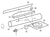
図12は、電子写真方式のプリンタ装置2001全体、特にエンジン部2003の概略構成を示す図である。本実施形態のプリンタはモノクロームレーザビームプリンタである。このプリンタはホストコンピュータ2104より入力した印刷データに基づいて得られる画像データで変調されたレーザ光をポリゴンミラー53により感光ドラム57を走査して静電潜像を形成する。そして、この静電潜像をトナー現像して可視画像を得、これを中間転写体709へ転写して可視画像を形成する。そして更に、この可視画像を転写材702へ転写し、転写材702上に可視画像を定着させる。以上の制御を行うエンジン部2003は、感光ドラム57を有するドラムユニット、接触帯電ローラ717を有する一次帯電部、クリーニング部、現像部、中間転写体709、用紙カセット701や各種ローラ703、704、705、707を含む給紙部、転写ローラ709を含む転写部及び定着部725によって構成されている。
FIG. 12 is a diagram illustrating a schematic configuration of the entire
ドラムユニット713は、感光ドラム(感光体)57と感光ドラム57のホルダを兼ねたクリーニング機構を有するクリーナ容器714とを一体に構成したものである。このドラムユニット713はプリンタ本体に対して着脱自在に支持され、感光ドラム57の寿命に合わせて容易にユニット交換可能に構成されている。感光ドラム57はアルミシリンダの外周に有機光導電体層を塗布して構成し、クリーナ容器714に回転可能に支持されている。感光ドラム57は、図示しない駆動モータの駆動力が伝達されて回転するもので、駆動モータは感光ドラム57を画像形成動作に応じて反時計回り方向に回転させる。感光ドラム57への露光は、スキャナ部730から送られるレーザ光を感光ドラム57の表面を選択的に露光させることにより静電潜像が形成されるように構成されている。スキャナ部730では、変調されたレーザ光を、モータ60により画像信号の水平同期信号を同期して回転するポリゴンミラーにより反射し、レンズ55、反射鏡56を介して感光ドラム57を照射する。
The
現像部は、静電潜像を可視画像化するために現像器721を備えた構成を有する。現像器721には、スリーブ722と、スリーブ722の外周に圧接する塗布ブレード723がそれぞれ設けられる。
The developing unit includes a developing
ブラック現像器721のスリーブ722は感光ドラム57に対して例えば300μm程度の微小間隔を持って配置されている。現像器721は、器内に内蔵された送り込み部材によってトナーを搬送すると共に、時計回り方向に回転するスリーブの外周に塗布ブレード723によって塗布するように摩擦帯電によってトナーへ電荷を付与する。また、スリーブ722に現像バイアスを印加することにより、静電潜像に応じて感光ドラム57に対して現像を行って感光ドラム57にブラックトナーによる可視画像を形成する。
The
中間転写体709は、感光ドラム57に接触して感光ドラム57の回転に伴って回転するように構成されたもので、カラー画像形成時に時計回り方向に回転し、感光ドラム57から可視画像の転写を受ける。また、中間転写体709は画像形成時に後述する転写ローラ710が接触して転写材702を挟持搬送することにより転写材702に中間転写体709上の可視画像を同時に転写する。中間転写体の外周部には、中間転写体709の回転方向に関する位置を検知するためのTOPセンサ709a及びRSセンサと、中間転写体に転写されたトナー像の濃度を検知するための濃度センサが配置されている。
The
転写ローラ710は、感光ドラム57に対して接離可能に支承された転写帯電器を備えたもので、金属軸を中抵抗発泡弾性体により巻回することによって構成されている。
The
転写ローラ710は、図8に実線で示すように中間転写体709上に可視画像を多重転写している間は、可視画像を乱さぬように下方に離開している。そして、中間転写体709上に可視画像が形成された後は、この可視画像を転写材702に転写するタイミングにあわせてカム部材(不図示)により転写ローラ710を図示点線で示す上方に位置させる。これにより転写ローラ710は転写材702を介して中間転写体709に所定の押圧力で圧接すると共に、バイアス電圧が印加され、中間転写体709上の可視画像が転写材702に転写される。
As shown by the solid line in FIG. 8, the
定着部725は、転写材702を搬送させながら、転写された可視画像を定着させるものであり、転写材702を加熱する定着ローラ726と、転写材702を定着ローラ726に圧接させるための加圧ローラ727とを備えている。定着ローラ726と加圧ローラ727とは中空状に形成され、内部にそれぞれヒータ728,729が内蔵されている。即ち、可視画像を保持した転写材702は定着ローラ726と加圧ローラ727とにより搬送されると共に、熱及び圧力を加えることによりトナーが表面に定着される。
The fixing
可視画像定着後の転写材702は、その後排紙ローラ734,735,736によって排紙部737へ排出して画像形成動作を終了する。
The
<光学走査ユニット>
図4は本実施形態を含む光学走査ユニットの構成図である。光学走査ユニットはエンジン部2003の一部である。光学走査ユニットは、半導体レーザ51やポリゴンミラー54、回転多面鏡駆動回路53、感光ドラム57等を含み、感光ドラム57上に画像データに応じた静電潜像を形成するユニットである。半導体レーザ51から出射したレーザビームはシリンドリカルレンズ52を通って回転多面鏡53に到達する。回転多面鏡53は、スキャナモータを含む回転多面鏡駆動回路54によって等角速度で回転している。レーザビームは、回転多面鏡54の回転速度に同期して、画像信号によってパルス幅変調されている。回転多面鏡53に到達したレーザビームは回転多面鏡53によって偏向され、f−θレンズ55によって平面に投影された光の線速度が等速度となるように変換される。このためレーザビームは、感光ドラム57の表面を長手方向に等速で走査する。また、f−θレンズ55を通ったレーザビームは、感光ドラム57の画像が形成される領域(画像領域という)を照射しない位置に設けられたビーム検出(以下BDと略す)センサ58により受光される。画像領域では、レーザビームはf−θレンズ55を通って反射ミラー56により反射され、感光ドラム57上を照射する。感光ドラム57は予備的に帯電されており、レーザビームの照射によって静電潜像が形成される。感光ドラム57に形成された静電潜像はトナーにより現像されてトナー像となり、トナー像が用紙に転写され定着されて用紙上に画像が形成される。
<Optical scanning unit>
FIG. 4 is a configuration diagram of an optical scanning unit including the present embodiment. The optical scanning unit is a part of the
<回転多面鏡の制御回路>
図6は、回転多面鏡を回転させるスキャナモータを制御するためのモータ駆動装置の概略図である。図6において、回転多面鏡制御部2002aには、目標速度値608、基準信号であるSCNCLK信号26が入力される。このほか、速度制御開始信号や速度可変命令信号等も入力される。回転多面鏡制御部2002aは、加速命令信号44および減速命令信号45を出力する。加速命令信号44および減速命令信号45は回転多面鏡駆動回路602に入力される。回転多面鏡駆動回路602からは3相ブラシレスモータ601を駆動するための駆動電流603,604,605が出力される。3相ブラシレスモータ601には位置検出素子606が設けられている。位置検出素子606からは3本の位置検出信号607が回転多面鏡駆動回路602に入力される。回転多面鏡駆動回路602は、モータ601の回転等には、検出されたモータ601の回転位相に応じたタイミングで駆動電流を出力してモータ601に電流を供給して回転させる。以下、各ブロックについて説明する。ただし、回転多面鏡制御部2002aに関しては、最後に詳しく説明する。
<Rotary polygon mirror control circuit>
FIG. 6 is a schematic diagram of a motor driving device for controlling a scanner motor that rotates the rotary polygon mirror. In FIG. 6, a
<回転多面鏡駆動回路>
図7は回転多面鏡駆動回路602のブロック図である。図8は回転多面鏡駆動回路のタイミングチャートである。図7において、701はチャージポンプ、702はチャージポンプコンデンサである。チャージポンプ701にアクティブ(この場合‘L’レベル)の加速命令信号44が入力されると、定電流がチャージポンプ701からチャージポンプコンデンサ702に流れて電荷が蓄積される(たとえば図8のタイミング801)。また、チャージポンプ701にアクティブ(この場合‘L’レベル)の減速命令信号45が入力されると、定電流がチャージポンプコンデンサ702からチャージポンプ701に流れ出して電荷を放電する(たとえば図8のタイミング802)。703は位相補償回路で、チャージポンプ出力708に対して、モータ特性に応じたゲイン及び位相調整を行う。マトリクス回路705は、予め設定した基準電圧710と比較し、位相補正出力709が基準電圧710より大きい時は駆動開始信号を出力する(たとえば図8のタイミング803)。位相補正出力709が基準電圧710より小さい時は駆動停止信号を出力する(たとえば図8のタイミング804)。両者が等しければ中立状態である(たとえば図8のタイミング805)。モータ素子駆動素子706は、マトリクス回路705からの駆動制御信号711に応じた駆動電流をモータ601に入力する。なお、駆動開始信号とは、駆動制御信号711によりモータを加速する信号状態にあるとき、その駆動制御信号711を指す。駆動停止信号とは、駆動制御信号711によりモータを減速する信号状態にあるとき、その駆動制御信号711を指す。
<Rotating polygon mirror drive circuit>
FIG. 7 is a block diagram of the rotary polygon
例として3相ブラシレスモータ601を駆動させる場合について説明する。図9は、マトリクス回路705の動作シーケンス図、図10はモータ駆動素子706の動作説明図である。図10に示すように、u,v,wという3相の各相ごとに2つ1組のトランジスタが設けられている。図10では各相の識別記号u,v,wが、トランジスタ名および信号名の添え字に付されている。また、1組のトランジスタの一方はアップ用であり他方はダウン用である。図10ではアップ用はトランジスタ名および信号名の添え字にupと、ダウン用は同じくdnと記載されている。とアップ用トランジスタとダウン用とは排他的にオンされる。一つの相のコイルに流される電流は、アップ用トランジスタをオンにした場合ととダウン用トランジスタをオンにした場合とで、その方向が逆となる。したがって増速時には、回転子の回転位相に応じたタイミング各相のコイルに電流を流すことで、引力と斥力とを生じさせて回転子を加速することができる。
As an example, a case where the three-
さて、図10の各トランジスタには図9の駆動制御信号が入力される。図9において、駆動制御信号711は、モータを駆動する駆動トランジスタ(Quup、Qudn、Qvup、Qvdn、Qvup、Qvdn)を制御するための制御信号の組である。制御信号には、信号CTLuup、CTLudn、CTLvup、CTLvdn、CTLwup、CTLwdnおよび電源切り替え信号が含まれる。駆動開始(加速)時には、モータ37に回転位相に応じて電流を供給し、回転を増速させるための駆動制御信号711がマトリクス回路705から出力される。駆動停止(減速)時には、トランジスタの上側(up用)をオン、下側(down用)をオフすることによりモータ601への通電を停止させる制御信号が出力される。駆動開始信号及び駆動停止信号の何れも出力しない状態では、例えば、トランジスタの制御信号(CTLuup、CTLudn、CTLvup、CTLvdn、CTLwup、CTLwdn)は駆動開始信号と同様の制御信号がマトリクス回路から出力される。ただし、電源切り替え信号がアクティブとなり、トランジスタへ供給する電源電圧レベルを減圧させてモータ601への供給電流が減少する。
Now, the drive control signal of FIG. 9 is input to each transistor of FIG. In FIG. 9, a
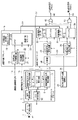
<回転多面鏡制御部>
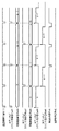
図1は第1の実施形態を示す回転多面鏡制御部2002aのブロック図である。回転多面鏡制御部2002aは、加速命令信号44および減速命令信号45を生成する。図2A−図2Cは、回転多面鏡制御部2002bの主要ブロックのタイミングチャートである。図2Bは例として回転数を減じる制御を行った場合の、図2Cは回転数を増す制御を行った場合の図である。
<Rotating polygon mirror control unit>
FIG. 1 is a block diagram of a rotary polygon
図1において、半導体レーザ51内のレーザダイオード(LD)1から出射したレーザビームL1は回転多面鏡53により偏向されBDセンサ58を含むBD回路2によりBD信号3を出力する。BD信号3はBD信号ゲートブロック4に入力され、速度可変カウントBD信号11および速度制御BD信号13が生成される。速度可変カウントBD信号11は、速度可変ブロック16に入力されて、速度可変カウンタ23のクロックとして使用される。速度制御BD信号13は、速度制御ブロック27に入力される。速度制御ブロック27には、カウンタ値24も入力されており、SNCCLK信号26をクロックとするカウンタa32およびカウンタb38によって生成されるカウント値に基づいて、加速命令信号44及び減速命令信号45が生成される。これら信号によって、前述の通りスキャナモータの回転速度が加速あるいは減速されて、一定速度で安定する。以下、各ブロックについて説明する。
In FIG. 1, a
[BD信号ゲートブロック]
BD信号3は、ビームBDゲートブロック4に入力される。BD信号3から、LPFで構成される波形整形回路5でノイズ成分が除去された後、BDゲート発生回路7に入力される。BDゲート発生回路7は、速度可変カウント用BDゲート信号8及び速度制御用BDゲート信号9を生成する。速度可変カウント用BDゲート信号8の周波数はビーム出力信号6の周波数の1/nに、速度制御用BDゲート信号9の周波数はビーム出力信号6の周波数の1/mとなるように設定される。また、いずれのゲート信号も、アクティブ(負論理)の期間にビーム出力信号6がアクティブとなるように同期がとられている。図2A−図2Cに示すタイミング図では、例としてm=4、n=2に設定している。
[BD signal gate block]
The
速度可変カウントBD信号発生回路10は、ビーム出力信号6をBDゲート発生回路7から入力される速度可変カウント用BDゲート信号8でゲートする。すなわち、2つの信号がともにアクティブである場合にアクティブとなる信号が出力される。本例では信号は負論理であるから、具体的には信号の論理和が出力される。こうすることにより、ビーム出力信号6から、速度可変カウント用BDゲート信号8と同周波数の成分が抽出されて速度可変カウント用BD信号11として出力される。
The speed variable count BD
一方速度制御BD信号発生回路12は、ビーム出力信号6をBDゲート発生回路7から入力される速度制御用BDゲート信号9でゲートする。すなわち、2つの信号がともにアクティブである場合にアクティブとなる信号が出力される。本例では信号は負論理であるから、具体的には信号の論理和が出力される。こうすることにより、ビーム出力信号6から、速度制御用BDゲート信号9と同周波数の成分が抽出されて速度制御BD信号13として出力される。図2Aおよび図2Bにその例を示す。速度可変カウントBD信号11は、ビーム検出信号6をn(すなわち2)分周した信号であり、速度制御BD信号13は、ビーム検出信号6をm(すなわち4)分周した信号である。
On the other hand, the speed control BD
[速度可変ブロック]
目標速度設定レジスタ19には、kビットの目標速度初期値20を格納する。目標速度初期値20は回転多面鏡が所定回転数時に出力されるBD信号3の基本周期のm倍(m≧1)とし、スキャナクロックSCNCLK(以下SCNCLKと略す)26の周期の倍数で表される。これは後述する速度制御ブロック27の動作クロックとしてSCNCLK26を用いているためである。分周比mおよびSCNCLKの周期は一定に決められるから、目標速度初期値20は、目標となるBD信号3の周期に応じて決定される。目標速度初期値は、最終的には目標速度に応じた値まで増加されるカウント値24の初期値である。望ましくは、現在の回転多面鏡の回転数に応じた値が設定される。また図1ではレジスタに値を設定するための機構は設けられていないが、不図示の制御回路から値を設定することができる。これは目標速度初期値は現在のスキャナモータの回転数に応じた値が設定されるのが望ましく、スキャナモータの回転数は変更され得るためである。
[Speed variable block]
The target
目標速度入力制御回路17は、不示図の本体制御回路から入力される速度制御開始信号14に応じて、目標速度初期値20を速度可変カウンタ23にロードするための初期値設定ロード信号18を生成する。
The target speed
可変範囲設定回路21は可変範囲設定信号22を出力する。可変範囲設定信号22は、不示図の本体制御回路から入力される速度可変命令信号15に応じて、速度可変カウンタ23の動作を開始させる。
The variable
速度可変カウンタ23は、可変範囲設定信号22の出力期間(アクティブな期間)に、ロードされた目標速度初期値20を初期値として、速度可変カウント用BD信号11に同期してカウントアップを行う。その出力はk’ビット(k’≧k)の可変速度値24として速度制御ブロック27へ出力される。図2Aの例では、目標速度初期値20をαとした場合、可変範囲設定信号22がアクティブ(負論理)出力されている間、速度可変カウンタ23はカウントアップ動作を行う。可変範囲設定信号22がインアクティブとなると、速度可変カウンタ23はカウントアップを停止する。図2Aでは、可変速度値24が7カウントした値(α+7)に至るとカウントは停止する。この値(α+7)がスキャナモータの回転数の目標値(目標速度)に相当する。後述するとおり、モータの回転速度は、カウント値に対応する目標速度に減速または加速されて、その速度で安定する。図2Aおよび図2Bでは、初期値20に対して回転周期を伸張したことにより回転多面鏡53の回転数が減少する。
The
[速度制御ブロック]
分周器28は、速度制御BD信号13を2分周した分周器出力信号29を生成し、それをカウント開始信号a発生回路30およびカウント開始信号b発生回路34に入力する(図2B参照)。カウント開始信号a発生回路30は、例えば分周器出力信号29の立上りエッジに同期したカウント開始信号a31を生成する。一方、カウント開始信号b発生回路34は、たとえば分周器出力信号29の立下りエッジに同期したカウント開始信号b35を生成する。
[Speed control block]
The
カウンタa32は、カウント開始信号a31を起点にSCNCLK発生回路25から入力されるSCNCLK26をカウントする。可変速度値aラッチ33は、可変速度値24をカウント開始信号a31に同期してラッチし、ラッチした値を可変速度値a34としてカウンタa32に出力する。カウンタa32は、カウント開始信号a31の立下りエッジから、初期値を0としてカウントを開始する。カウンタa32は、カウント値が可変速度値a34に達するまでカウントを続行する。なお、カウンタa32が、カウント値が可変速度値a34に達することをカウンタa32が満了する、という。これは他のカウンタについても同様である。カウンタa出力信号35はカウント開始信号a31の立下りエッジに同期して立ち上がり、可変速度値a34と一致した点で立ち下がるパルスとなる。すなわち、カウンタaの出力信号35は、カウント開始信号a31の立下りエッジに同期して立ち上がり、(SCNCLKの周期ts)×(可変速度値a34の値)の期間が経過すると立ち下がる信号である。
The counter a32 counts SCNCLK 26 input from the
同様にカウンタb38はカウント開始信号b37を起点にSCNCLK26をカウントする。可変速度値bラッチ39は、可変速度値24をカウント開始信号b37に同期してラッチし、ラッチした値を可変速度値b40としてカウンタb36に出力する。カウンタb38は、カウンタb出力信号41の立ち下がりエッジから、初期値を0としてカウントを開始する。カウンタb38は、カウント値が可変速度値b40に達するまでカウントを続行する。カウンタb出力信号41はカウント開始信号b37の立下りエッジに同期して立ち上がり、可変速度値b40と一致した点で立ち下がるパルスとなる。すなわち、カウンタbの出力信号41は、カウント開始信号b37の立下りエッジに同期して立ち上がり、(SCNCLKの周期ts)×(可変速度値b40の値)の期間が経過すると立ち下がる信号である。
Similarly, the counter b38 counts
ORゲート42は、カウンタa出力信号35とカウンタb出力信号41との論理を生成し、その論理和信号を加速命令信号44として出力する。加速命令信号のロウレベルの期間に、チャージポンプキャパシタはチャージされて、モータを加速する制御信号が出力される。すなわち加速命令信号44は負論理の信号であるといえる。加速命令信号44が負(すなわちアクティブ)となるのは、カウンタa32とカウンタb38のいずれか一方が満了し、他方のカウントが開始されるまでの期間である。カウンタa32とカウンタb38とのうち少なくともいずれか一方が必ずカウント動作をしているのであれば、加速命令信号44はアクティブとはならない。
The
NANDゲート43は、カウンタa出力信号35とカウンタb出力信号41とのNAND信号を生成して、そのNAND信号を減速命令信号45として出力する。減速命令信号のロウレベルの期間に、チャージポンプキャパシタは放電されて、モータを減速する制御信号が出力される。すなわち減速命令信号45は負論理の信号であるといえる。減速命令信号45が負(すなわちアクティブ)となるのは、カウンタa32とカウンタb38の両方が平行してカウントしている期間である。カウンタa32とカウンタb38とのうち、多くともいずれか一方しかカウント動作をしているのであれば、減速命令信号45はアクティブとはならない。
The
たとえば、可変速度aラッチ33にラッチされる値と、可変速度bラッチ39にラッチされる値がひとしく、一定であると仮定する。ラッチされる値は、ビーム検出信号の周期(すなわち回転多面鏡モータの回転周期)をm倍した時間をSCNCLKの周期によって示した値である。この場合、回転多面鏡の回転周期のm倍の時間が、カウンタa32及びカウンタb38でカウントされる時間と等しければ、加速命令信号44も減速命令信号45もアクティブになることはない。回転多面鏡の回転周期が短くなり(すなわち回転が速くなり)回転多面鏡の回転周期のm倍の時間が、カウンタa32及びカウンタb38でカウントされる時間よりも短くなると、カウンタa32及びカウンタb38とは並列にカウント動作する期間が生じる。その期間に対応して減速命令信号45はロウレベル(アクティブ)になり、モータは減速する。逆に、回転多面鏡の回転周期のm倍の時間が、カウンタa32及びカウンタb38でカウントされる時間よりも長くなると、カウンタa32及びカウンタb38のいずれもが動作していない期間が生じる。その期間に対応して加速命令信号44はロウレベル(アクティブ)になり、モータは加速する。この結果、回転多面鏡を駆動するモータの回転速度は、回転多面鏡が、可変速度aラッチ33および可変速度bラッチ39にラッチされた値に対応する回転速度となる値で安定する。
For example, assume that the value latched by the variable speed a
本実施形態では、可変速度aラッチ33および可変速度bラッチ39に与える値を、望ましくは回転多面鏡の現在の回転速度に対応した値を初期値とし、目標の回転速度に対応した値まで段階的に(本例では1ずつ)増加させる。こうすることで、回転速度の目標値が、最終的な目標値に達するまで漸増していくために、円滑な速度制御を実現できる。それによって、速度変化に要する時間を短縮できる。
In this embodiment, the values given to the variable speed a
図2Bは減速時の信号の例を示す。目標初期値はαであり、α+7が目標値である。目標値は、目標となる回転多面鏡の回転速度に応じて決定される。すなわち図2Bの例では、初期値で示される期間に対して7×ts(SCNCLKの周期)を加えた期間が、目標となる回転多面鏡の回転周期である。したがって、不図示の本体制御部は、速度可変カウントBD信号11の7周期に相当する時間、速度可変命令信号15をアクティブに維持する。
FIG. 2B shows an example of a signal during deceleration. The target initial value is α, and α + 7 is the target value. The target value is determined according to the rotational speed of the target rotary polygon mirror. That is, in the example of FIG. 2B, a period obtained by adding 7 × ts (the SCNCLK period) to the period indicated by the initial value is the target rotation period of the rotary polygon mirror. Therefore, the main body control unit (not shown) keeps the speed
図2Cは加速時の信号のタイミングの一例を示す。加速時には、最終的な目標値が目標値の初期値よりも小さくなるため、カウンタa32およびカウンタb38でカウントされる値は徐々に短くなる。その結果、加速命令信号44がロウレベル(アクティブ)になる期間が生じ、回転多面鏡を駆動するモータは加速する。
FIG. 2C shows an example of signal timing during acceleration. At the time of acceleration, since the final target value is smaller than the initial value of the target value, the values counted by the counter a32 and the counter b38 are gradually shortened. As a result, a period in which the
<制御の例>
図3は第1の実施形態における回転多面鏡制御部の動作概要図である。この例では、回転多面鏡53の現在の回転数Pは32000[rpm]、面数Nは12である。また、BD信号3の周期τbdは、τbd=1/(R×N/60)=1/(32000×12/60)=156.25[μs]となる。目標速度初期値20は、τbd×mをSCNCLKの1周期を単位として表した値であり、(τbd×m)/(SCNCLK26の周期)と表せる。速度制御BD信号13の分周設定値mは4であるから、SCNCLK26の周波数を16MHzとすると、目標速度初期値20は、156.25μs×4×16MHz=10000となる。
<Example of control>
FIG. 3 is an operation schematic diagram of the rotary polygon mirror control unit in the first embodiment. In this example, the current rotational speed P of the
一方、速度可変カウント用BD信号11の分周設定値nが2であり、速度可変カウンタに設定される値はビーム検出信号のm(本例ではm=4)倍であるから、速度制御毎の可変速度値24の値は4/2=2である。すなわち速度の制御はn×τbdの周期を単位とするのに対して、可変速度値24のカウント周期はm×τbdであり、可変速度値24が2変化するごとに、目標速度値が1単位(すなわちSCNCLKの1周期)変化する。目標速度初期値20を10000とした場合、制御比率は2/10000=0.02[%]となる。すなわち、本実施形態のモータ制御装置は、目標速度初期値が10000であれば、回転多面鏡の速度を、0.02パーセントずつ加速あるいは減速させる制御を行うことができる。
On the other hand, the frequency division setting value n of the speed variable count BD signal 11 is 2, and the value set in the speed variable counter is m (m = 4 in this example) times the beam detection signal. The value of the
したがって、回転多面鏡53の回転数を1[%]減じるためには、速度可変カウンタ23は、ロードされた目標速度初期値20から初めて、その1[%]アップした値までカウントする。すなわち、速度可変命令信号15を、可変速度カウンタ23がカウントを開始してから1[%]アップした値となるまでアクティブに維持する。初期値が10000であれば、1パーセントは100であるから、速度可変カウンタ23が100カウントするまで、速度可変命令信号15はアクティブに維持される。なお、たとえば可変範囲設定回路21にこの変化させる値をセットし、可変範囲設定回路21は、速度可変カウント用BD信号11をセットされた値だけ数え終えたなら速度可変命令信号15がインアクティブになるように構成することもできる。
Therefore, in order to reduce the rotation speed of the
さて、速可変カウント数の100は、速度制御BD信号13の50周期すなわち31.250[ms](=156.25μs×4×50)に相当する。したがって、多面鏡の回転数にして32000rpm(速度可変カウント値にして10000に相当)から1%減速して31680rpm(速度可変カウント値にして10100に相当)に減速するまでに、31.250msの時間を要することになる。これは加速時においても同様である。
The speed variable count number 100 corresponds to 50 periods of the speed
[変形例]
さてここで、図1の速度可変ブロック16の変形例を説明する。図1の速度可変カウンタ23はアップカウントするカウントとしているが、本例ではアップカウントとダウンカウントの切り替え信号を持つ。そして、目標速度初期値レジスタ19とともに、最終目標速度値レジスタを持つ。たとえば図3の例では、目標速度初期値レジスタ19に10000が、最終目標速度値レジスタに10100がセットされる。そして、目標速度初期値レジスタ19の値と、最終目標速度値レジスタの値とを比較する比較器をさらに備える。その比較の結果、目標速度初期値レジスタ19の値の方が大きければ(すなわち加速ならば)、カウンタ23の切り替え信号は「ダウンカウント」となる。逆であれば(すなわち減速ならば)、「アップカウント」となる。さらに、可変範囲設定回路21は、速度可変命令信号15がいったんアクティブにされると、不図示の可変範囲終了信号がアクティブになるまで可変範囲設定信号22をアクティブにするように構成される。速度可変カウンタ24の出力は、第1実施形態同様速度制御ブロック27に入力されると共に、比較器に入力される。比較器のもうひとつの入力には、最終目標速度値レジスタが接続されている。すなわちこの比較器は速度可変カウンタ24の値と最終目標速度値レジスタの値とを比較する。両者が等しければ、出力信号である可変範囲終了信号をアクティブにする。この結果、可変範囲設定信号22がインアクティブになって速度可変カウンタ23によるカウントは停止する。他の構成は前述した第1実施形態と同様である。
[Modification]
Now, a modification of the
このようにすることで、目標速度初期値から最終目標速度値まで、段階的に回転多面鏡の駆動モータを加速または減速できる。さらに、最終目標速度値を不図示の本体制御部によりあらかじめ算出してレジスタに設定しておけば、最終目標速度でモータ及び多面鏡は安定駆動される。 In this way, the drive motor of the rotary polygon mirror can be accelerated or decelerated stepwise from the target speed initial value to the final target speed value. Furthermore, if the final target speed value is calculated in advance by a main body control unit (not shown) and set in the register, the motor and the polygon mirror are stably driven at the final target speed.
第1実施形態及び変形例に示した本発明をまとめると以下のように説明できる。すなわち、回転多面鏡の駆動用モータの回転周期あるいはその整数倍の値をカウンタ値で表す。これを、周期指数という。そして、目標回転数の周期に相当する周期指数のパルス幅をもつ信号を2つ生成する。それらの信号の位相は180度ずらされている。これら2つの信号が実施形態のカウント出力信号a35およびカウント出力信号b41に相当する。目標回転数に対応する周期指数が、現在の回転数に対応する周期指数よりも短ければ、前記2つのパルスには間隙が生じる。この間隙が加速命令信号となる。逆に目標回転数に対応する周期指数が、現在の回転数に対応する周期指数よりも長ければ、前記2つのパルスには重複が生じる。この重複が減速命令信号となる。間隙も重複もなければ、その周期指数が目標回転数に対応する周期指数である。このときは加速命令信号も減速命令信号もない。ただしある信号が出力されるとは、その信号がアクティブとなるということであり、アクティブでない間でも実際にはインアクティブレベルの信号が出力され続けている。ここで本件発明では、目標とする周期指数を、現在の多面鏡の回転数に対応する周期指数の時間が経過する毎に、ある初期値から一定数ずつ、カウンタにより増加(減速時)あるいは減少(加速時)させて出力する。すなわちこのカウンタが周期指数の出力手段となる。ある初期値とは望ましくは現在の多面鏡の回転数に対応する周期指数の値である。また一定数とは実施形態では1である。 The present invention shown in the first embodiment and the modification can be summarized as follows. That is, the rotation period of the driving motor for the rotary polygon mirror or a value that is an integer multiple thereof is represented by a counter value. This is called a periodic index. Then, two signals having a pulse width with a cycle index corresponding to the cycle of the target rotational speed are generated. The phases of these signals are shifted by 180 degrees. These two signals correspond to the count output signal a35 and the count output signal b41 of the embodiment. If the periodic index corresponding to the target rotational speed is shorter than the periodic index corresponding to the current rotational speed, a gap occurs between the two pulses. This gap becomes an acceleration command signal. On the contrary, if the cycle index corresponding to the target rotation speed is longer than the cycle index corresponding to the current rotation speed, the two pulses are overlapped. This overlap is a deceleration command signal. If there is no gap or overlap, the cycle index is a cycle index corresponding to the target rotational speed. At this time, there is no acceleration command signal or deceleration command signal. However, the output of a signal means that the signal becomes active, and an inactive level signal continues to be output even while it is not active. Here, according to the present invention, the target periodic index is increased (during deceleration) or decreased by a certain number from a certain initial value every time the period index corresponding to the current rotational speed of the polygon mirror elapses. (When accelerating) and output. That is, this counter becomes a period exponent output means. The initial value is preferably a value of a periodic index corresponding to the current rotational speed of the polygon mirror. Further, the certain number is 1 in the embodiment.
[第2の実施形態]
図5は、第3の実施形態における回転検出回路のブロック図である。60はスキャナモータ、61はホール素子で磁束密度の磁界を受感させることにより電位差が発生する。r1およびr2はホール素子61にバイアスを加えるバイアス抵抗である。スキャナモータ60の回転によりホール素子61から電圧が出力される。62のホール信号増幅部で、OPアンプ63により差動増幅回路を構成している。バイアス回路64は回転検出信号65の直流レベルを調整するが接地しても良い。ホール信号増幅部62にて所定の増幅率に増幅された回転検出信号65は第1の実施形態におけるBD信号3に変わる信号として回転多面鏡53の速度制御信号として用いる。動作については同様のため以下は省略する。
[Second Embodiment]
FIG. 5 is a block diagram of a rotation detection circuit according to the third embodiment. 60 is a scanner motor, 61 is a Hall element, and a potential difference is generated by sensing a magnetic field of magnetic flux density. r1 and r2 are bias resistors for applying a bias to the
以上の通り、画像形成装置における両面印字の際に定着直後の用紙に印字された画像に対する伸長に対して、スキャナモータの回転数を可変制御することにより主副の走査時間を可変することにより熱変化による印字画像の補正が可能となる。 As described above, when the double-sided printing in the image forming apparatus is performed, the main / sub scanning time is varied by variably controlling the rotation speed of the scanner motor with respect to the expansion of the image printed on the sheet immediately after fixing. The print image can be corrected by the change.
特に、スキャナモータ回転数の可変速制御により、ある回転数で定常回転しているモータを異なる回転数で定常回転させるためには、モータの慣性モーメントに起因して長時間を要する。このため、モータの変速制御を開始してから目標回転数で定常回転するまでの時間、画像形成を開始することができず、印刷時間が長引き、印刷処理の生産性の向上を妨げる原因となっていた。これは副走査方向についても同様である。本実施形態の装置は、モータの回転数を変化させて定常回転させるまでの時間を短縮することで、印刷処理を遅延させることなく、また、形成される画像の画素数を変えることなく、シート上に形成される画像サイズを変更することができる。 In particular, it takes a long time due to the moment of inertia of the motor in order to cause the motor that is constantly rotating at a certain rotation speed to rotate at a different rotation speed by variable speed control of the scanner motor rotation speed. For this reason, the image formation cannot be started for the time from the start of the gear shift control to the steady rotation at the target rotation speed, which causes the printing time to be prolonged and hinders the improvement of the productivity of the printing process. It was. The same applies to the sub-scanning direction. The apparatus according to the present embodiment reduces the time required for steady rotation by changing the number of rotations of the motor, so that the printing process is not delayed and the number of pixels of the formed image is not changed. The size of the image formed on the top can be changed.
以上説明したように、本発明の実施形態及びその変形例によれば、画像形成装置における両面印字の際に定着直後の用紙に印字された画像に対する伸長に対して、スキャナモータの回転数を可変制御する。こうすることにより主副の走査時間を可変とし、熱変化による印字画像の補正が可能となるという効果を奏する。さらに、補正の際にスムースにスキャナモータの回転を変化させ目標とする回転数に迅速に到達させることができる。 As described above, according to the embodiment of the present invention and the modification thereof, the rotation speed of the scanner motor can be changed with respect to the expansion of the image printed on the sheet immediately after fixing in the double-sided printing in the image forming apparatus. Control. This makes it possible to make the main and sub scanning times variable and to correct the printed image due to thermal changes. Furthermore, it is possible to quickly change the rotation speed of the scanner motor during correction to quickly reach the target rotation speed.
またスキャナモータ回転数の可変速制御において、急激な変速制御はモータの慣性モーメントによる影響から制御時間に長時間を要するのに対して、変速制御における変速比率を低くする。こうすることにより、スキャナモータの慣性モーメントの影響を抑えることが可能となり、制御時間の短縮化が図れるという効果を奏する。 In the variable speed control of the scanner motor rotation speed, a rapid shift control requires a long control time due to the influence of the moment of inertia of the motor, whereas the shift ratio in the shift control is lowered. By doing so, the influence of the moment of inertia of the scanner motor can be suppressed, and the control time can be shortened.
なお本発明は、複数の機器(例えばホストコンピュータ、インタフェイス機器、リーダ、プリンタなど)から構成されるシステムに適用しても、一つの機器からなる装置(例えば、複写機、ファクシミリ装置など)に適用してもよい。また本発明の目的は、前述の実施形態の機能を実現するプログラムコードを記録した記録媒体を、システムあるいは装置に供給し、そのシステムあるいは装置のコンピュータが記憶媒体に格納されたプログラムコードを読み出し実行することによっても達成される。この場合、記憶媒体から読み出されたプログラムコード自体が前述した実施形態の機能を実現することになり、そのプログラムコード自体およびプログラムコードを記憶した記憶媒体は本発明を構成することになる。 Note that the present invention can be applied to a system (for example, a copier, a facsimile machine, etc.) consisting of a single device even if it is applied to a system composed of a plurality of devices (eg, a host computer, interface device, reader, printer, etc.). You may apply. Another object of the present invention is to supply a recording medium recording a program code for realizing the functions of the above-described embodiments to a system or apparatus, and the system or apparatus computer reads out and executes the program code stored in the storage medium. Is also achieved. In this case, the program code itself read from the storage medium realizes the functions of the above-described embodiments, and the program code itself and the storage medium storing the program code constitute the present invention.
また、本発明には、プログラムコードの指示に基づき、コンピュータ上で稼働しているオペレーティングシステム(OS)などが実際の処理の一部または全部を行い、その処理によって前述した実施形態の機能が実現される場合も含まれる。さらに、記憶媒体から読み出されたプログラムコードが、コンピュータに挿入された機能拡張カードやコンピュータに接続された機能拡張ユニットに備わるメモリに書込まれた場合についても、本発明は適用される。その場合、書き込まれたプログラムコードの指示に基づき、その機能拡張カードや機能拡張ユニットに備わるCPUなどが実際の処理の一部または全部を行い、その処理によって前述した実施形態の機能が実現される。 Further, according to the present invention, the operating system (OS) running on the computer performs part or all of the actual processing based on the instruction of the program code, and the functions of the above-described embodiments are realized by the processing. This is also included. Furthermore, the present invention is also applied to the case where the program code read from the storage medium is written into a memory provided in a function expansion card inserted into the computer or a function expansion unit connected to the computer. In that case, based on the instruction of the written program code, the CPU of the function expansion card or the function expansion unit performs part or all of the actual processing, and the functions of the above-described embodiments are realized by the processing. .
1 レーザダイオード(LD)
2 ビーム検出(BD)回路
4 ビーム検出(BD)信号ゲートブロック
7 ビーム検出(BD)ゲート信号発生回路
10 速度可変カウント用ビーム検出(BD)信号発生回路
12 速度制御用ビーム検出(BD)信号発生回路
16 速度可変ブロック
17 目標速度入力制御回路
19 目標速度設定レジスタ
21 可変範囲設定回路
23 速度可変カウンタ
25 スキャナクロック(SCCLK)発生回路
27 速度制御ブロック
28 分周器(1/2)
30 カウント開始信号a発生回路
32 カウンタa
33 可変速度値aラッチ
36 カウント開始信号b発生回路
38 カウンタb
39 可変速度値bラッチ
44 加速命令信号
45 減速命令信号
1 Laser diode (LD)
2 Beam detection (BD) circuit 4 Beam detection (BD)
30 Count start signal a generating
33 Variable speed value a
39 Variable speed
Claims (4)
前記レーザを検出しビーム検出信号を出力するビーム検出手段と、
前記ビーム検出信号の周波数を(1/m)に分周して前記回転多面鏡の速度制御クロック信号とする速度制御クロック生成手段と、
前記ビーム検出信号の周波数を(1/n)に分周して前記回転多面鏡の速度可変クロックとする可変速度クロック発生手段と、
前記回転多面鏡があらかじめ定めた回転数で回転する際の該ビーム検出信号の周期をm倍にした値を前記回転多面鏡の目標速度値として格納する目標速度設定手段と、
前記目標速度値を初期値とし前記速度可変クロックによりカウントアップあるいはカウントダウンすることにより回転多面鏡の目標速度を可変する目標速度可変手段と、
前記目標速度可変手段のカウントアップあるいはカウントダウン値を設定する可変範囲設定手段と、
基準クロック信号を生成する基準クロック信号発生手段と、
前記基準クロック信号を以って前記速度制御クロック信号の奇数番目にカウントを開始し、前記目標速度可変手段出力値までカウントする第1カウント手段と、
前記基準クロック信号を以って前記速度制御クロック信号の偶数番目にカウントを開始し、前記目標速度可変手段出力値までカウントする第2カウント手段とを有し、
前記第1カウント手段と前記第2カウント手段の両方がカウント停止している期間は回転多面鏡の駆動手段に加速命令信号を出力し、
前記第1カウント手段と前記第2カウント手段の両方がカウント動作をしている期間は回転多面鏡の駆動手段に減速命令信号を出力し、
前記第1カウント手段と前記第2カウント手段の一方がカウント動作をしている期間は回転多面鏡の駆動手段に加速命令信号及び減速命令信号の何れも出力しないことにより回転多面鏡の回転数を可変速制御することを特徴とする回転多面鏡制御装置。 In an image forming apparatus that forms a latent image on the image carrier by scanning the image carrier with light reflected by a rotary polygon mirror of a laser modulated based on an image signal, the rotation period of the rotary polygon mirror is detected. And a rotation polygon mirror that controls the rotation number of the rotation polygon mirror by outputting an acceleration command signal or a deceleration command signal by comparing the rotation cycle and the reference cycle with a rotation cycle at a predetermined rotation number as a reference cycle. A control device,
Beam detection means for detecting the laser and outputting a beam detection signal;
A speed control clock generating means for dividing the frequency of the beam detection signal into (1 / m) to be a speed control clock signal of the rotary polygon mirror;
Variable speed clock generating means for dividing the frequency of the beam detection signal into (1 / n) to be a variable speed clock of the rotary polygon mirror;
Target speed setting means for storing, as a target speed value of the rotary polygon mirror, a value obtained by multiplying the period of the beam detection signal when the rotary polygon mirror rotates at a predetermined rotation number by m times;
Target speed variable means for varying the target speed of the rotary polygon mirror by counting up or counting down with the speed variable clock with the target speed value as an initial value;
Variable range setting means for setting a count-up or count-down value of the target speed variable means;
Reference clock signal generating means for generating a reference clock signal;
First counting means for starting counting to an odd number of the speed control clock signal with the reference clock signal and counting to the target speed variable means output value;
A second counting means that starts counting to the even-numbered speed control clock signal with the reference clock signal and counts up to the target speed variable means output value;
During the period when both the first counting means and the second counting means are stopped, an acceleration command signal is output to the driving means of the rotary polygon mirror,
During the period when both the first counting means and the second counting means are counting, a deceleration command signal is output to the driving means of the rotary polygon mirror,
During the period when one of the first counting means and the second counting means is counting, neither the acceleration command signal nor the deceleration command signal is output to the driving device of the rotary polygon mirror, so that the rotational speed of the rotary polygon mirror is set. A rotary polygon mirror control device characterized by variable speed control.
前記速度可変クロックの前記ビーム検出信号に対する分周比nを前記速度制御クロック信号の前記ビーム検出信号に対する分周比m以上とすることを特徴とする請求項1に記載の回転多面鏡制御装置。 The division ratio m of the speed control clock signal to the beam detection signal is the same value as the number of surfaces of the rotary polygon mirror, an integer multiple value, or a factor value within the number of surfaces of the rotary polygon mirror,
2. The rotary polygon mirror control device according to claim 1 , wherein a division ratio n of the speed variable clock with respect to the beam detection signal is greater than or equal to a division ratio m of the speed control clock signal with respect to the beam detection signal.
前記回転多面鏡の回転周期を検出し回転検出信号を出力する回転検出手段と、
前記回転検出信号の周波数を(1/p)に分周して前記回転多面鏡の速度制御クロック信号とする速度制御クロック生成手段と、
前記回転検出信号の周波数を(1/q)に分周して前記回転多面鏡の速度可変クロックとする可変速度クロック発生手段と、
前記回転多面鏡があらかじめ定めた回転数で回転する際の前記ビーム検出信号の周期をp倍にした値を前記回転多面鏡の目標速度値として格納する目標速度設定手段と、
前記目標速度値を初期値とし前記速度可変クロックによりカウントアップあるいはカウントダウンすることにより回転多面鏡の目標速度を可変する目標速度可変手段と、
前記目標速度可変手段のカウントアップあるいはカウントダウン値を設定する可変範囲設定手段と、
基準クロック信号を生成する基準クロック信号発生手段と、
前記基準クロック信号を以って前記速度制御クロック信号の奇数番目にカウントを開始し、前記目標速度可変手段出力値までカウントする第1カウント手段と、
前記基準クロック信号を以って前記速度制御クロック信号の偶数番目にカウントを開始し、前記目標速度可変手段出力値までカウントする第2カウント手段とを有し、
前記第1カウント手段と前記第2カウント手段の両方がカウント停止している期間は回転多面鏡の駆動手段に加速命令信号を出力し、
前記第1カウント手段と前記第2カウント手段の両方がカウント動作をしている期間は回転多面鏡の駆動手段に減速命令信号を出力し、
前記第1カウント手段と前記第2カウント手段の一方がカウント動作をしている期間は回転多面鏡の駆動手段に加速命令信号及び減速命令信号の何れも出力しないことにより回転多面鏡の回転数を可変速制御することを特徴とする回転多面鏡制御装置。 In an image forming apparatus that forms a latent image on the image carrier by scanning the image carrier with light reflected by a rotary polygon mirror of a laser modulated based on an image signal, the rotation period of the rotary polygon mirror is detected. Rotating polygon mirror control that controls the number of rotations of the rotating polygon mirror by outputting the acceleration command signal or the deceleration command signal by comparing the rotation cycle with the reference cycle at the rotation cycle at a predetermined rotation speed A device,
Rotation detection means for detecting a rotation period of the rotary polygon mirror and outputting a rotation detection signal;
A speed control clock generating means for dividing the frequency of the rotation detection signal into (1 / p) to obtain a speed control clock signal of the rotary polygon mirror;
A variable speed clock generating means that divides the frequency of the rotation detection signal into (1 / q) to make a speed variable clock of the rotary polygon mirror;
Target speed setting means for storing, as a target speed value of the rotary polygon mirror, a value obtained by multiplying the period of the beam detection signal by p times when the rotary polygon mirror is rotated at a predetermined rotation number;
Target speed variable means for varying the target speed of the rotary polygon mirror by counting up or counting down with the speed variable clock with the target speed value as an initial value;
Variable range setting means for setting a count-up or count-down value of the target speed variable means;
Reference clock signal generating means for generating a reference clock signal;
First counting means for starting counting to an odd number of the speed control clock signal with the reference clock signal and counting to the target speed variable means output value;
A second counting means that starts counting to the even-numbered speed control clock signal with the reference clock signal and counts up to the target speed variable means output value;
During the period when both the first counting means and the second counting means are stopped, an acceleration command signal is output to the driving means of the rotary polygon mirror,
During the period when both the first counting means and the second counting means are counting, a deceleration command signal is output to the driving means of the rotary polygon mirror,
During the period when one of the first counting means and the second counting means is counting, neither the acceleration command signal nor the deceleration command signal is output to the driving device of the rotary polygon mirror, so that the rotational speed of the rotary polygon mirror is set. A rotary polygon mirror control device characterized by variable speed control.
前記速度可変クロックの前記回転検出信号に対する分周比qを前記速度制御クロック信号の前記ビーム検出信号に対する分周比p以上とすることを特徴とする請求項3に記載の回転多面鏡制御装置。 A frequency dividing ratio m of the speed control clock signal to the rotation detection signal is set to the same value, an integer multiple value, or a factor value as the number of pulses of the rotation detection signal output while the rotary polygon mirror makes one round,
4. The rotary polygon mirror control device according to claim 3 , wherein a frequency division ratio q of the speed variable clock to the rotation detection signal is equal to or higher than a frequency division ratio p of the speed control clock signal to the beam detection signal.
Priority Applications (1)
| Application Number | Priority Date | Filing Date | Title |
|---|---|---|---|
| JP2006051169A JP4817883B2 (en) | 2006-02-27 | 2006-02-27 | Rotary polygon mirror controller |
Applications Claiming Priority (1)
| Application Number | Priority Date | Filing Date | Title |
|---|---|---|---|
| JP2006051169A JP4817883B2 (en) | 2006-02-27 | 2006-02-27 | Rotary polygon mirror controller |
Publications (3)
| Publication Number | Publication Date |
|---|---|
| JP2007236031A JP2007236031A (en) | 2007-09-13 |
| JP2007236031A5 JP2007236031A5 (en) | 2009-04-16 |
| JP4817883B2 true JP4817883B2 (en) | 2011-11-16 |
Family
ID=38556062
Family Applications (1)
| Application Number | Title | Priority Date | Filing Date |
|---|---|---|---|
| JP2006051169A Expired - Fee Related JP4817883B2 (en) | 2006-02-27 | 2006-02-27 | Rotary polygon mirror controller |
Country Status (1)
| Country | Link |
|---|---|
| JP (1) | JP4817883B2 (en) |
Families Citing this family (1)
| Publication number | Priority date | Publication date | Assignee | Title |
|---|---|---|---|---|
| JP5765915B2 (en) | 2009-12-22 | 2015-08-19 | キヤノン株式会社 | Image forming apparatus |
Family Cites Families (1)
| Publication number | Priority date | Publication date | Assignee | Title |
|---|---|---|---|---|
| JP4371628B2 (en) * | 2002-04-01 | 2009-11-25 | キヤノン株式会社 | Image forming apparatus and control method thereof |
-
2006
- 2006-02-27 JP JP2006051169A patent/JP4817883B2/en not_active Expired - Fee Related
Also Published As
| Publication number | Publication date |
|---|---|
| JP2007236031A (en) | 2007-09-13 |
Similar Documents
| Publication | Publication Date | Title |
|---|---|---|
| JP5510125B2 (en) | Image forming apparatus and brushless motor control program | |
| JP6702768B2 (en) | Image forming device | |
| JP2011209565A (en) | Image forming apparatus | |
| JP5246520B2 (en) | Optical scanning apparatus, image forming apparatus, and control program | |
| JPH1134390A (en) | Image-forming apparatus | |
| US8068751B2 (en) | Image forming apparatus | |
| JP4817883B2 (en) | Rotary polygon mirror controller | |
| JP4881012B2 (en) | Image forming apparatus | |
| JP4850639B2 (en) | Motor control device, motor control method, and electrophotographic image forming apparatus | |
| US10289020B2 (en) | Laser scanning device capable of detecting abnormal state, image forming apparatus, abnormality detection method | |
| JP6525571B2 (en) | Image forming device | |
| JP2014168907A (en) | Image formation apparatus, light source lighting control method and program | |
| JP2012113233A (en) | Light beam scanner, image forming device, and light beam scanning method | |
| JP2001282052A (en) | Image forming device | |
| JP6781808B2 (en) | Motor control device, sheet transfer device, document reader and image forming device | |
| JP2017171477A (en) | Image formation apparatus | |
| JP2006154250A (en) | Image forming apparatus | |
| JP2008026792A (en) | Image forming apparatus | |
| JP2005168138A (en) | Motor controller, image forming apparatus, and motor control method | |
| JP2008110517A (en) | Image forming apparatus | |
| JP6350496B2 (en) | Image forming apparatus | |
| JP2000289247A (en) | Imaging apparatus | |
| JP5676994B2 (en) | Image forming apparatus | |
| JP4823922B2 (en) | Optical scanning system | |
| JP2003224996A (en) | Drive method for stepping motor |
Legal Events
| Date | Code | Title | Description |
|---|---|---|---|
| A521 | Written amendment |
Free format text: JAPANESE INTERMEDIATE CODE: A523 Effective date: 20090227 |
|
| A621 | Written request for application examination |
Free format text: JAPANESE INTERMEDIATE CODE: A621 Effective date: 20090227 |
|
| A977 | Report on retrieval |
Free format text: JAPANESE INTERMEDIATE CODE: A971007 Effective date: 20110613 |
|
| A131 | Notification of reasons for refusal |
Free format text: JAPANESE INTERMEDIATE CODE: A131 Effective date: 20110617 |
|
| A521 | Written amendment |
Free format text: JAPANESE INTERMEDIATE CODE: A523 Effective date: 20110808 |
|
| TRDD | Decision of grant or rejection written | ||
| A01 | Written decision to grant a patent or to grant a registration (utility model) |
Free format text: JAPANESE INTERMEDIATE CODE: A01 Effective date: 20110826 |
|
| A01 | Written decision to grant a patent or to grant a registration (utility model) |
Free format text: JAPANESE INTERMEDIATE CODE: A01 |
|
| A61 | First payment of annual fees (during grant procedure) |
Free format text: JAPANESE INTERMEDIATE CODE: A61 Effective date: 20110830 |
|
| FPAY | Renewal fee payment (event date is renewal date of database) |
Free format text: PAYMENT UNTIL: 20140909 Year of fee payment: 3 |
|
| FPAY | Renewal fee payment (event date is renewal date of database) |
Free format text: PAYMENT UNTIL: 20140909 Year of fee payment: 3 |
|
| LAPS | Cancellation because of no payment of annual fees |