JP4817719B2 - Image forming system and post-processing apparatus - Google Patents
Image forming system and post-processing apparatus Download PDFInfo
- Publication number
- JP4817719B2 JP4817719B2 JP2005156198A JP2005156198A JP4817719B2 JP 4817719 B2 JP4817719 B2 JP 4817719B2 JP 2005156198 A JP2005156198 A JP 2005156198A JP 2005156198 A JP2005156198 A JP 2005156198A JP 4817719 B2 JP4817719 B2 JP 4817719B2
- Authority
- JP
- Japan
- Prior art keywords
- sheet
- processing
- post
- rfid tag
- information
- Prior art date
- Legal status (The legal status is an assumption and is not a legal conclusion. Google has not performed a legal analysis and makes no representation as to the accuracy of the status listed.)
- Expired - Fee Related
Links
- 238000012805 post-processing Methods 0.000 title claims description 136
- 238000000034 method Methods 0.000 claims description 75
- 238000007639 printing Methods 0.000 claims description 73
- 230000015572 biosynthetic process Effects 0.000 claims description 56
- 238000012545 processing Methods 0.000 claims description 56
- 238000007599 discharging Methods 0.000 claims description 3
- 238000009499 grossing Methods 0.000 claims 1
- 230000027455 binding Effects 0.000 description 41
- 238000009739 binding Methods 0.000 description 41
- 230000015654 memory Effects 0.000 description 24
- 238000012937 correction Methods 0.000 description 21
- 238000003860 storage Methods 0.000 description 13
- 239000012467 final product Substances 0.000 description 11
- 230000006870 function Effects 0.000 description 11
- 239000012790 adhesive layer Substances 0.000 description 8
- 238000003825 pressing Methods 0.000 description 6
- 239000000853 adhesive Substances 0.000 description 5
- 230000001070 adhesive effect Effects 0.000 description 5
- 238000010586 diagram Methods 0.000 description 5
- 239000000203 mixture Substances 0.000 description 5
- 239000000047 product Substances 0.000 description 5
- 238000012546 transfer Methods 0.000 description 5
- 239000010410 layer Substances 0.000 description 4
- 238000004891 communication Methods 0.000 description 3
- 238000013500 data storage Methods 0.000 description 3
- 230000003028 elevating effect Effects 0.000 description 3
- 238000007726 management method Methods 0.000 description 3
- 239000004065 semiconductor Substances 0.000 description 3
- 238000000926 separation method Methods 0.000 description 3
- 238000004804 winding Methods 0.000 description 3
- 230000007423 decrease Effects 0.000 description 2
- 238000009826 distribution Methods 0.000 description 2
- 230000000694 effects Effects 0.000 description 2
- 238000005516 engineering process Methods 0.000 description 2
- 239000003292 glue Substances 0.000 description 2
- 239000002184 metal Substances 0.000 description 2
- 229910052751 metal Inorganic materials 0.000 description 2
- 239000011347 resin Substances 0.000 description 2
- 229920005989 resin Polymers 0.000 description 2
- 238000011144 upstream manufacturing Methods 0.000 description 2
- 239000003086 colorant Substances 0.000 description 1
- 230000008878 coupling Effects 0.000 description 1
- 238000010168 coupling process Methods 0.000 description 1
- 238000005859 coupling reaction Methods 0.000 description 1
- 238000011161 development Methods 0.000 description 1
- 208000010727 head pressing Diseases 0.000 description 1
- 238000010438 heat treatment Methods 0.000 description 1
- 238000003384 imaging method Methods 0.000 description 1
- 230000010365 information processing Effects 0.000 description 1
- 239000000696 magnetic material Substances 0.000 description 1
- 239000000463 material Substances 0.000 description 1
- 238000004806 packaging method and process Methods 0.000 description 1
- 238000004080 punching Methods 0.000 description 1
- 239000007779 soft material Substances 0.000 description 1
- 239000002699 waste material Substances 0.000 description 1
Images


Classifications
-
- G—PHYSICS
- G06—COMPUTING; CALCULATING OR COUNTING
- G06K—GRAPHICAL DATA READING; PRESENTATION OF DATA; RECORD CARRIERS; HANDLING RECORD CARRIERS
- G06K15/00—Arrangements for producing a permanent visual presentation of the output data, e.g. computer output printers
- G06K15/02—Arrangements for producing a permanent visual presentation of the output data, e.g. computer output printers using printers
-
- B—PERFORMING OPERATIONS; TRANSPORTING
- B42—BOOKBINDING; ALBUMS; FILES; SPECIAL PRINTED MATTER
- B42C—BOOKBINDING
- B42C19/00—Multi-step processes for making books
- B42C19/06—Multi-step processes for making books starting with webs not provided for elsewhere
-
- G—PHYSICS
- G06—COMPUTING; CALCULATING OR COUNTING
- G06K—GRAPHICAL DATA READING; PRESENTATION OF DATA; RECORD CARRIERS; HANDLING RECORD CARRIERS
- G06K17/00—Methods or arrangements for effecting co-operative working between equipments covered by two or more of main groups G06K1/00 - G06K15/00, e.g. automatic card files incorporating conveying and reading operations
- G06K17/0022—Methods or arrangements for effecting co-operative working between equipments covered by two or more of main groups G06K1/00 - G06K15/00, e.g. automatic card files incorporating conveying and reading operations arrangements or provisions for transferring data to distant stations, e.g. from a sensing device
- G06K17/0025—Methods or arrangements for effecting co-operative working between equipments covered by two or more of main groups G06K1/00 - G06K15/00, e.g. automatic card files incorporating conveying and reading operations arrangements or provisions for transferring data to distant stations, e.g. from a sensing device the arrangement consisting of a wireless interrogation device in combination with a device for optically marking the record carrier
-
- B—PERFORMING OPERATIONS; TRANSPORTING
- B42—BOOKBINDING; ALBUMS; FILES; SPECIAL PRINTED MATTER
- B42P—INDEXING SCHEME RELATING TO BOOKS, FILING APPLIANCES OR THE LIKE
- B42P2261/00—Manufacturing; Forming
- B42P2261/04—Producing books by printing sheets in following order, e.g. for ordering via the Internet
Landscapes
- Engineering & Computer Science (AREA)
- General Engineering & Computer Science (AREA)
- Physics & Mathematics (AREA)
- General Physics & Mathematics (AREA)
- Theoretical Computer Science (AREA)
- Computer Networks & Wireless Communication (AREA)
- Folding Of Thin Sheet-Like Materials, Special Discharging Devices, And Others (AREA)
- Accessory Devices And Overall Control Thereof (AREA)
- Control Or Security For Electrophotography (AREA)
Description
本発明は画像形成システム、特に、電子写真方式あるいは静電記録式などによる複写機・プリンタ・オンデマンド印刷機などの画像形成装置と製本や紙折りなど画像形成後の後処理を行なう後処理装置とを含む画像形成システムに関し、更に、該画像形成システムを構成する後処理装置に関するものである。
The present invention relates to an image type Narushi stems, in particular, after performing post-processing after image formation, such as folding the image forming apparatus and bookbinding and paper such as an electrophotographic method or an electrostatic recording type, such as by a copying machine, printer, on-demand printing machine relates to an image forming system including a processor, also it relates to the post-processing apparatus constituting the image forming system.
シートなどの印刷媒体への従来の印刷処理は、原稿から製版を製作する製版工程、製版から実際にインクを載せる刷版(さっぱん)を製作する刷版工程、この刷版を印刷機に取り付け印刷を行なう印刷工程、と多くの工程を要し、その成果物を得るために多大な時間を要する。又、製版・刷版を製作する工数や印刷機の調整工数、印刷機自体の設備費など非常に高いコストを要する。このため、印刷における高いコストを低減するためには、大量の印刷を行うこと、コストパフォーマンスを低減することが必須の条件であった。 The conventional printing process for printing media such as sheets consists of a plate making process for making a plate making from a manuscript, a plate making process for producing a printing plate on which ink is actually placed from the plate making, and attaching this printing plate to a printing machine. A printing process for performing printing and many processes are required, and a great deal of time is required to obtain the product. In addition, very high costs are required, such as man-hours for plate making and printing plates, man-hours for adjusting the printing press, and equipment costs for the printing press itself. For this reason, in order to reduce the high cost in printing, it was indispensable to perform a large amount of printing and to reduce cost performance.
しかし、近年、情報処理技術並びに印刷デバイスの機能が発展するに伴い、DTP(Desk Top Publishing)等で作成されたデジタルデータを、製版・刷版工程を経ずに電子写真方式等によるプリンタで直接印刷できるようになり、小部数の印刷を短納期で実行することが可能になっている。又、これら印刷デバイスにはフィニッシャーやソータ、コレータ(丁合機)、封書作成または製本機など後処理装置が付属している場合もあり、これらの後処理装置を正確に動作させるための印刷属性を設定することで、印刷から製本処理に至る一連の作業がほとんど人手を介さずに一気に処理できるようになって来ている。この技術はいわゆるオンデマンド印刷と呼ばれる技術分野であり、小規模ロットの印刷や、個別メッセージを印刷したダイレクトメールの印刷を低コストで実現するものである。このような印刷デバイスと後処理装置によるシステムでは、一般にこれらを直列に接続し、印刷デバイスに搭載された制御部を後処理装置とオンラインで接続することによって後処理装置を含めて一括で制御する。 However, in recent years, with the development of information processing technology and printing device functions, digital data created by DTP (Desk Top Publishing) etc. can be directly transferred to a printer using an electrophotographic method, etc. without going through plate making and printing plate processes. Printing is now possible, and it is possible to print a small number of copies with a short delivery time. In addition, these printing devices may have post-processing devices such as finishers, sorters, collators (collating machines), sealed letter making or bookbinding machines, and printing attributes for operating these post-processing devices accurately. With this setting, a series of operations from printing to bookbinding can be processed at a stretch with little manual intervention. This technology is a technical field called so-called on-demand printing, and realizes printing of small lots and direct mail printing of individual messages at a low cost. In a system using such a printing device and a post-processing apparatus, these are generally connected in series, and a control unit mounted on the printing device is connected to the post-processing apparatus online to control the post-processing apparatus and the like collectively. .
しかしながら、オンデマンド印刷の請負業者は、通常複数の印刷デバイスを所有し、印刷依頼者の依頼する部数や種類によって印刷デバイスを使い分けることになる。例えば、カラーページと白黒ページとが混載された印刷物を製作する場合、カラーページはカラープリンタで、白黒ページはモノクロプリンタで印刷する。これは、カラープリンタは白黒印刷のコストが白黒専用プリンタより高いからである。この例のように最終的な成果物がカラーと白黒の印刷物が混載されたものの場合、少なくともどちらかの印刷デバイスから印刷物を人手で取り出し、他方と合流させなければならない。このような割り込みがある状態で、片方の印刷デバイスの制御部で後処理装置を制御して、自動でカラー・白黒混載の成果物を製作するのは困難である。 However, an on-demand printing contractor usually has a plurality of printing devices, and uses different printing devices depending on the number and type of copies requested by the print requester. For example, when producing a printed matter in which a color page and a monochrome page are mixedly mounted, the color page is printed by a color printer, and the monochrome page is printed by a monochrome printer. This is because a color printer has a higher monochrome printing cost than a monochrome printer. When the final product is a mixture of color and black-and-white prints as in this example, the prints must be manually removed from at least one of the printing devices and merged with the other. In the state where there is such an interruption, it is difficult to automatically produce a color / monochrome mixed product by controlling the post-processing apparatus by the control unit of one printing device.
一方、最終成果物の形態にも、シート束を中央で折り、その折り部をホチキス等で綴じ止めする中綴じ製本、シートを折らずにその端部をホチキス等で綴じ止めする簡易製本、シート束の背をバインドテープ等で糊付けするくるみ製本等がある。これらに対応する為、中綴じ製本・簡易製本を行なうフィニッシャーと、くるみ製本を行なうくるみ製本機等、複数の後処理装置を使い分ける必要がある。 On the other hand, even in the form of the final product, saddle-stitched binding in which a sheet bundle is folded at the center and the folded portion is stapled with a staple, etc. There are case bindings that glue the back of the bundle with binding tape. In order to cope with these, it is necessary to use a plurality of post-processing devices such as a finisher that performs saddle stitching and simple binding and a case binding machine that performs case binding.
従って、複数の印刷デバイスに対し複数の後処理装置をそれぞれ個別に直列配置したりオンライン接続すると、必要となる印刷デバイス及び後処理装置が重複して多大な設備の無駄が発生してしまうことになる。そこで、複数の印刷デバイスで様々な後処理装置を共用する場合、それぞれの装置に制御部を持ち印刷デバイスの制御部とは接続されていないオフラインの後処理装置が有用である。ところが、オフラインの後処理装置を複数連携させて成果物を得る場合、後処理装置毎に印刷属性の設定を手動でする必要があり作業が煩雑であるうえ、誤設定をする可能性があるという問題点がある。 Therefore, if a plurality of post-processing devices are individually arranged in series or connected online to a plurality of printing devices, the necessary printing devices and post-processing devices are duplicated, resulting in a great waste of equipment. Become. Therefore, when various post-processing apparatuses are shared by a plurality of printing devices, an offline post-processing apparatus that has a control unit in each apparatus and is not connected to the control unit of the printing device is useful. However, when obtaining a deliverable by linking multiple offline post-processing devices, it is necessary to manually set the print attribute for each post-processing device, which is cumbersome and may be misconfigured. There is a problem.
これに対し、例えば特許文献1では、印刷デバイスで印刷属性に対応したバーコードを印刷物自体に印刷付加し、これを後処理装置上流側の用紙パス上に配置されたバーコードリーダで読取り、後処理装置を制御する例が示されている。又、特許文献2の例では、印刷デバイスで印刷属性に対応した「ジョブシート」を印刷物とは別に印刷する。ジョブシートには印刷属性等を示す複数の文字情報と、それに対応したバーコードが記載されている。オペレータはジョブシートを後処理装置上に載置し、所望の処理に対応するバーコード部を後処理装置上に配置されたハンディ・バーコードリーダで選択することで後処理装置を制御するのである。このようにして、オフラインの後処理装置であっても個別に印刷属性等の設定をすることなくオンラインにおける後処理並みに後処理作業の自動化が可能となる。
しかしながら、複数のオフラインの後処理装置を連携させて成果物を得る場合、印刷物がどの時点の後処理まで完了しているかを知り得ることは、特に異種ジョブを混合して処理しなければならない場合の誤操作を防ぐ上で必要である。これを可能にするためには印刷物に後処理の履歴を残しておく必要がある。 However, when obtaining a product by linking multiple offline post-processing devices, knowing at what point the post-processing of the printed product is completed can be done especially when different jobs must be mixed and processed It is necessary to prevent misoperation. In order to make this possible, it is necessary to leave a history of post-processing on the printed matter.
ところが、上記従来例で用いられるバーコードは書き換えができないので、後処理履歴を印刷物やジョブシートに残すことができない。 However, since the barcode used in the conventional example cannot be rewritten, the post-processing history cannot be left on the printed matter or job sheet.
すなわち、特許文献1の例のように印刷物に印刷属性をバーコードで付加する場合、バーコードは情報化密度が低く、一方で成果物に大きなバーコードが印刷されているのは外観上問題があるため情報量が限定され、複数の後処理の連携情報のような高度な印刷属性を付加することができない。又、特許文献2の例では、ジョブシートにまずオペレータがペン等で記入し次にそれに対応するバーコードをバーコードリーダで読み取って印刷属性を付加することが記載されている。従って、その作業自体が煩雑であり、しかもオペレータのペン入力ミスやバーコード読取り選択ミスが発生する恐れがある。
That is, when a print attribute is added to a printed matter with a barcode as in the example of
ところで、近年普及が著しい技術分野に無線周波数識別(RFID)タグ(以降RFIDタグと呼ぶ)がある。このRFIDタグはバッテリーレスで、専用のリーダライタでその内部のメモリ内にあるデータの読み出し・書き込みを非接触で行なうことができる。又、メモリ素子を使用するため情報化密度が非常に高い。更に、大きさも1mm以下の「μチップ」(株式会社日立製作所製)と呼ばれるものも開発され、様々な媒体への実装性も高い。 By the way, a radio frequency identification (RFID) tag (hereinafter referred to as an RFID tag) is a technical field that has been widely spread in recent years. This RFID tag is battery-less and can read and write data in its internal memory in a non-contact manner with a dedicated reader / writer. Moreover, since the memory element is used, the information density is very high. In addition, a so-called “μ chip” (manufactured by Hitachi, Ltd.) having a size of 1 mm or less has been developed, and is highly mountable on various media.
本発明の目的は、上記画像形成処理における問題点に鑑み、RFIDタグによって複数のオフラインの後処理装置を連携させるような複雑な印刷属性の受け渡しを可能にすることで、作業のさらなる自動化を図り、オンデマンド印刷における生産性を大幅に向上させることにある。本発明は、かかる画像形成システム、更に、画像形成システムを構成する後処理装置を提供する。
In view of the above problems in the image forming process, an object of the present invention is to further facilitate the work by enabling delivery of complicated print attributes such that a plurality of offline post-processing devices are linked by an RFID tag. It is to greatly improve the productivity in on-demand printing. The present invention, such an image type Narushi stem further provides a post-processing apparatuses constituting the image forming system.
かかる課題を解決するために、本発明の画像形成システムは、後処理を含むジョブ情報に基づいて記録媒体上に画像形成して該記録媒体を排出する画像形成手段と、排出された前記記録媒体に少なくとも前記ジョブ情報と前記画像形成に応じて設定される画像形成固有情報とを含む属性情報を書込んだRFIDタグを付帯するRFIDタグ付帯手段とを有する少なくとも1つの画像形成装置と、前記RFIDタグから前記属性情報を読み取る読取手段と、前記読み取られた属性情報に基づいて前記記録媒体の後処理を制御する制御手段と、前記記録媒体に付帯したRFIDタグに後処理が完了したことを示す履歴情報を含む後処理固有情報を前記属性情報として付加する書込手段とを有する少なくとも1つの後処理装置とを有することを特徴とする。
In order to solve this problem, an image forming system of the present invention includes an image forming unit that forms an image on a recording medium based on job information including post-processing, and discharges the recording medium, and the discharged recording medium At least one image forming apparatus including an RFID tag attached means for attaching an RFID tag to which attribute information including at least the job information and image formation unique information set according to the image formation is written, and the RFID A reading means for reading the attribute information from the tag, a control means for controlling the post-processing of the recording medium based on the read attribute information, and the RFID tag attached to the recording medium indicating that the post-processing is completed And at least one post-processing device having writing means for adding post-processing specific information including history information as the attribute information .
ここで、前記画像形成固有情報は、画像形成を行なった時刻情報、画像濃度情報、両面印刷か片面印刷かを識別する印刷モード情報のうち少なくとも1つを含む。また、前記後処理装置のうち少なくとも1つは、前記ジョブ情報と前記画像形成固有情報とに基づいて記録媒体の反りを補正して平滑化する反り補正手段を更に有する。また、前記RFIDタグ付帯手段は、画像形成した記録媒体毎に前記RFIDタグを付帯する。
Here, before Symbol image forming specific information includes time information to perform image formation, the image density information, at least one of the print mode information identifying whether duplex printing or simplex printing. Further, at least one of the post-processing devices further includes a warp correction unit that corrects and smoothes the warp of the recording medium based on the job information and the image formation unique information. Further, the RFID tag attachment means attaches the RFID tag to each recording medium on which an image is formed .
又、本発明の画像形成システムは、後処理を含むジョブ情報に基づいて記録媒体上に画像形成して該記録媒体を排出する画像形成手段と、排出された前記記録媒体に少なくとも前記ジョブ情報と前記画像形成に応じて設定される画像形成固有情報とを含む属性情報を書込んだRFIDタグを付帯するRFIDタグ付帯手段とを有する少なくとも1つの画像形成装置と、前記RFIDタグから前記属性情報を読み取る読取手段と、前記読み取られた属性情報に基づいて前記記録媒体の後処理を制御する制御手段とを有する少なくとも1つの後処理装置とを有し、前記RFIDタグ付帯手段は、前記ジョブ情報と前記画像形成固有情報とに基づいて記録媒体の反り量を予測し、前記予測値が所定の反り量を超えた記録媒体に前記RFIDタグを付帯させることを特徴とする。
Further, the image forming system of the present invention includes an image forming means for forming an image on a recording medium based on job information including post-processing and discharging the recording medium, and at least the job information on the discharged recording medium. At least one image forming apparatus having an RFID tag attached means for attaching an RFID tag to which attribute information including attribute information including image formation unique information set according to the image formation is written, and the attribute information from the RFID tag. At least one post-processing device that includes a reading unit that reads and a control unit that controls post-processing of the recording medium based on the read attribute information, and the RFID tag-attached unit includes the job information, A warping amount of a recording medium is predicted based on the image formation unique information, and the RFID tag is attached to a recording medium whose predicted value exceeds a predetermined warping amount .
又、本発明の後処理装置は、画像形成された記録媒体に付帯されたRFIDタグから、後処理を含むジョブ情報と画像形成に応じて設定される画像形成固有情報とを含む属性情報を読み取る読取手段と、前記読み取られた属性情報に基づいて前記記録媒体の後処理を制御する制御手段と、前記制御手段に制御される、RFIDタグを付帯する前記記録媒体を供給するトレイと、所定数の前記記録媒体毎に製本処理をする製本手段と、製本処理が終了すると前記RFIDタグの内容を消去する消去手段と、を有することを特徴とする。ここで、前記制御手段に制御される、RFIDタグを付帯する前記記録媒体を供給する複数のトレイと、該複数のトレイからの前記記録媒体を丁合い処理する丁合い手段と、丁合い処理の終了を前記RFIDタグに書込む書込手段とを更に有する。
The post-processing apparatus of the present invention reads attribute information including job information including post-processing and image formation unique information set in accordance with image formation from an RFID tag attached to the image-formed recording medium. A reading means; a control means for controlling post-processing of the recording medium based on the read attribute information ; a tray for supplying the recording medium with an RFID tag controlled by the control means; and a predetermined number A bookbinding unit that performs a bookbinding process for each of the recording media, and an erasing unit that erases the contents of the RFID tag when the bookbinding process is completed . Here, a plurality of trays for supplying the recording medium attached with the RFID tag controlled by the control means, a collating means for collating the recording medium from the plurality of trays, and collating processing Write means for writing the end into the RFID tag .
以上述べたように、本発明によれば、RFIDタグを記録媒体に添付することで、1つの後処理装置で、或いは複数のオフラインの後処理装置を連携し、作業を自動化できる画像形成システムが構築できる為、オンデマンド印刷における生産性を大幅に向上させることが可能となる。 As described above, according to the present invention, there is provided an image forming system capable of automating work by attaching an RFID tag to a recording medium, in one post-processing device or in cooperation with a plurality of offline post-processing devices. Since it can be constructed, productivity in on-demand printing can be greatly improved.
本発明は、上記効果を奏する画像形成システムを構成する後処理装置を提供できる。 The present invention can provide a post-processing apparatus that constitutes the image imaging system that Sosu the above effect.
以下、本発明の実施形態を添付図面を用いて説明する。尚、本実施形態では各シートにRFIDタグを付帯する第1の動作例と、「反り補正」が必要なシートのみにRFIDタグを付帯する第2の動作例との2つの具体例を示すが、例えばシート束の上下端のシートあるいはいずれかにはRFIDタグを付帯する等の、付帯するRFIDタグの使用数がかかる具体例の中間である種々の例が考えられ、開示された基本的な内容の範囲である限り本発明はこれらも含むものである。 Hereinafter, embodiments of the present invention will be described with reference to the accompanying drawings. In this embodiment, two specific examples are shown: a first operation example in which an RFID tag is attached to each sheet, and a second operation example in which an RFID tag is attached only to a sheet that requires “warping correction”. Various examples in which the number of attached RFID tags is intermediate between such specific examples, such as attaching RFID tags to the upper and lower sheets of the sheet bundle or any of them, are considered and disclosed. As long as it is within the scope of the contents, the present invention includes these.
<本実施形態の画像形成システムの構成例>
図1は、本発明に係る実施形態の画像形成システムの概略構成を示す図である。
<Example of Configuration of Image Forming System of Present Embodiment>
FIG. 1 is a diagram showing a schematic configuration of an image forming system according to an embodiment of the present invention.
本画像形成システムは、各種文書・図形をアプリケーションソフトウェアを動作させて作成し、プリンタドライバと呼ばれる起動ソフトウェアでこれらの文書を出力する為のコンピュータ100、この信号を受けてシートに画像形成を行なうためのフルカラープリンタ101及びモノクロプリンタ102、これらのプリンタから出力されたシートを取り出しセットすると指定された順番でモノクロプリントシートとカラープリントシートを混合し丁合いするコレータ103、コレータにより丁合いが済んだシート束をセットして最終的な成果物を得るくるみ製本機104及び簡易製本用のフィニッシャ105から構成される。
In this image forming system, various documents and graphics are created by operating application software, and a
各プリンタの制御部101a、102aは、コンピュータ100とネットワーク100aを介してオンラインで接続され、それぞれに応じた画像情報及び共通情報である後処理情報を含むジョブ情報が分配される。
The
各プリンタ101、102のシート搬送方向下流側には、RFIDタグ106aをシート106に添付するRFIDタグ付帯装置201-1、201-2が接続されている。各RFIDタグ付帯装置201-1、201-2は、タグ貼付器202-1、202-2とRFIDタグに情報を書き込むリーダライタ203-1、203-2が備わり、前記制御部101a、102aによって前記ジョブ情報を含むシート属性情報が書き込まれる。尚、リーダライタ203-1、203-2は書込み専用であってもよい。
At the downstream side in the sheet conveying direction of the
各プリンタ101、102と各後処理装置103、104、105とは、装置間が電気的に接続されておらず、当該後処理装置はオフライン型の後処理装置となっている。各後処理装置には、RFIDタグ106aの情報を読取り、各後処理の固有情報を書き込むリーダライタ103b、104b、105bが備わり、シート106を介して伝達されるシート属性情報に基づきそれぞれの制御部103a、104a、105aによって後処理がなされる。尚、後述するように実際には、リーダライタ103b、104b、105bは読取り用のリーダライタ303、304、402、502と、書込み用のリーダライタ306、407、507とからなり、それぞれ読取り専用、書込み専用であってもよい。
The
又、画像形成装置101、102及び後処理装置103、104、105の間のシート束の受け渡し101d、102d、103c、103dは、オペレータによる手作業でも、搬送装置による自動作業でもよい。
The
尚、図1に示す破線のネットワーク100bは、コンピュータ100と後処理装置103、104、105とを接続する他の例であり、コンピュータ100が画像形成装置101、102と各後処理装置103、104、105とを総合的に管理することを可能とするものであり、例えば、各制御部101a〜105aへの制御プログラムのダウンロードによる入れ替えなどを行なって、システムを第1の動作例の仕様にしたり第2の動作例の仕様にするなど柔軟にシステム変更することも可能になる。
A
以下に、本実施形態の画像形成システムを構成する各構成要素について、更に説明する。尚、以下の説明では、画像形成装置であるプリンタ101、102とRFIDタグ付帯装置201とを独立した装置として説明するが、上述の如くRFIDタグ付帯装置201はプリンタ101、102の制御部101a、102aにより制御されるのが一般的であり、通常オプションとして付加されるが、予めプリンタ101、102内に一体化していても構わない。
Below, each component which comprises the image forming system of this embodiment is further demonstrated. In the following description, the
(カラープリンタ101の構成例)
次に、カラープリンタ101の構成例について、図2を用いて説明する。
(Configuration example of color printer 101)
Next, a configuration example of the
図2は、カラープリンタ101の概略構成を示す側面図であり、同図において、1013はポリゴンミラーで、4つ(C、M、Y、K)の半導体レーザより発光された4本のレーザ光を受ける。4本のレーザ光の内の最初の一本は、ミラー1014、1015、1016を経て感光ドラム1017を走査し、次の1本は、ミラー1018、1019、1020を経て感光ドラム1021を走査し、次の1本は、ミラー1022、1023、1024を経て感光ドラム1025を走査し、次の1本は、ミラー1026、1027、1028を経て感光ドラム1029を走査する。
FIG. 2 is a side view showing a schematic configuration of the
1030はイエロー(Y)のトナーを供給する現像器であり、レーザ光に従い、感光ドラム1017上にイエローのトナー像を形成する。1031はマゼンタ(M)のトナーを供給する現像器であり、レーザ光に従い、感光ドラム1021上にマゼンタのトナー像を形成する。1032はシアン(C)のトナーを供給する現像器であり、レーザ光に従い、感光ドラム1025上にシアンのトナー像を形成する。1033はブラック(K)のトナーを供給する現像器であり、レーザ光に従い、感光ドラム1029上にブラックのトナー像を形成する。
A developing
以上、4色(Y、M、C、K)のトナー像が出力媒体であるシートに転写され、フルカラーの出力画像を得ることができる。 As described above, toner images of four colors (Y, M, C, K) are transferred to a sheet as an output medium, and a full-color output image can be obtained.
シートカセット1034、1035及び手差しトレイ1036のいずれかより供給されたシートは、レジストローラ1037を経て、転写ベルト1038上に吸着されて搬送される。このシートの供給のタイミングと同期がとられて、予め感光ドラム1017、1021、1025、1029には各色のトナーが現像されており、シートの搬送と共に該シートにトナーが転写される。各色のトナーが転写されたシートは、分離されて搬送ベルト1039により搬送され、定着器1040によってトナーが加圧及び加熱されて溶融しシートに定着される。定着器1040を通過したシートは、装置外部へ排出する。又、フラッパ1050により一旦下方向へ導かれて、シートの後端がフラッパ1050を通過した後、スイッチバックさせてこれにより、各シートは、フェイスダウン状態で装置外部へ排出することや、そのままシートが反転した状態で再び転写ベルト1038へ導き裏面に画像形成されて両面プリントされたシートを得ることも可能である。尚、4つの感光ドラム1017、1021、1025、1029は、距離dを存して等間隔に配置されている。シートは、搬送ベルト1029により一定速度Vで搬送され、このタイミングの同期がとられて、4つの半導体レーザは駆動される。
The sheet supplied from any one of the
(モノクロプリンタ102の構成例)
次に、モノクロプリンタ102の構成について、図3を用いて説明する。
(Configuration example of monochrome printer 102)
Next, the configuration of the
図3は、モノクロプリンタ102の概略構成を示す側面図であり、同図において、1113はポリゴンミラーで、半導体レーザより発光されたレーザ光を受ける。このレーザ光は、ミラー1114、1115、1116を経て感光ドラム1117を走査する。1130は黒色のトナーを供給する現像器で、レーザ光に従い、感光ドラム1117上にトナー像を形成し、該トナー像がシートに転写され、出力画像を得ることができる。
FIG. 3 is a side view showing a schematic configuration of the
シートカセット1134、1135及び手差しトレイ1136のいずれかより供給されたシートは、レジストローラ1137を経て転写ベルト1138上に吸着されて搬送される。このシートの供給のタイミングと同期がとられて、予め感光ドラム1117にはトナーが現像されており、シートの搬送と共に、トナーがシートに転写される。トナーが転写されたシートは分離されて、定着器1140によって、トナーが加圧及び加熱されて溶融しシートに定着される。定着器1140を通過したシートは、装置外部へ排出される。又、フラッパ1050により一旦下方向へ導かれて、シートの後端がフラッパ1050を通過した後、スイッチバックさせてこれにより、各シートは、フェイスダウン状態で装置外部へ排出することや、そのままシートが反転した状態で再び転写ベルト1138へ導き裏面に画像形成されて両面プリントされたシートを得ることも可能である。
A sheet supplied from any one of the
(RFIDタグ付帯装置201の構成例)
次に、RFIDタグ付帯装置201の構成について、図4を用いて説明する。尚、RFIDタグ付帯装置201は各プリンタ101、102の下流側に配置されるが、ここではカラープリンタ101に配置された場合の説明をする。
(Configuration example of RFID tag attached device 201)
Next, the configuration of the RFID tag attached
プリンタにより画像形成されたシートは、矢印a方向に搬送され、タグ貼付器202によって所定の位置にRFIDタグが添付される。そして、リーダライタ203でシート属性情報をRFIDタグ内のメモリ部に書き込み、トレイ204に排出する。尚、図4のタグ貼付器202が図1のタグ貼付器202-1、202-2に相当し、リーダライタ203がリーダライタ203-1、203-2に相当する。
The sheet on which the image is formed by the printer is conveyed in the direction of arrow a, and an RFID tag is attached to a predetermined position by the
(RFIDタグ及びタグシートの構成例)
次に、RFIDタグの構成について、図5を用いて説明する。
(Configuration example of RFID tag and tag sheet)
Next, the configuration of the RFID tag will be described with reference to FIG.
RFIDタグ20は、メモリ部21をマウントしてアンテナパターン22を形成した薄肉回路基板であるフレキシブル回路基板23により板状に形成されている。又、このRFIDタグ20はバッテリーレスであって、該RFIDタグ20のアンテナパターン22から、リーダーライタ203が備えるコイル状のアンテナ部203a(図6参照)を介して、電磁界結合される。
The
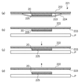
図9に、本実施形態で仕様されるタグシート221の詳細構成例を示す。
FIG. 9 shows a detailed configuration example of the
タグシート221は、複数のRFIDタグ20がベーステープ222上に配列されたものである。
The
図9の(a)に示すようにベーステープ222上には粘着層223が形成され、これによってRFIDタグ20はベーステープ上に仮固定されている。又、RFIDタグ20のベーステープ側と反対面は粘着層225が形成されている。ベーステープ222及びRFIDタグ20を覆うように剥離テープ223が粘着層223、225によって仮固定されている。
As shown in FIG. 9A, an
シートPにRFIDタグ20を貼り付ける時は、図9の(b)のように剥離テープ224を剥離する。粘着層223、225のそれぞれベーステープ222、RFIDタグ20に対する接着力は、剥離テープ224に対する接着力より強く設定されているため、剥離テープのみがタグシート221から剥離する。
When the
この状態で、図9の(c)のようにシートPとRFID側粘着層225のみが接触するように接触・加圧する。
In this state, as shown in FIG. 9C, contact and pressurization are performed so that only the sheet P and the RFID-side
次に、図9の(d)のようにタグシート221をシートPから離間させると、粘着層225によるRFIDタグ20とシートPの接着力は、粘着層223とRFIDタグ20間の接着力よりも強く設定されているため、RFIDタグ20はタグシートから剥離し、シートPに固着される。
Next, when the
次に、タグ貼付器202及びリーダライタ203の詳細構成について、図6乃至図8を用いて説明する。
Next, detailed configurations of the
図6に示すように、タグ貼付器202はRFIDタグ付帯装置201本体に固定されたガイド211にタグシート保持部212が上下方向に移動自在に支持され、図示しない昇降手段で駆動される。タグシート221は、タグシート保持部212に回転自在に支持されるタグシートボビン213から、同じく回転自在に支持されるベース巻取りカラー216の矢印b方向の回転により引き出される。タグシート221は、更に、タグシート保持部212にヘッド加圧部材215によって上下方向移動自在に付勢された貼付ヘッド214によって、シートPと対向するように張架される。又、タグシートボビン213及びタグシート221の剥離テープ224を巻き取る剥離テープ巻取りカラー217は図示しない付勢手段によりそれぞれ矢印c、dの回転方向に付勢され、ヘッド加圧部材215とともにタグシート221が緩むのを防止している。
As shown in FIG. 6, the
以下、タグシート221を用いてタグ貼付器202によってRFIDタグ20をシートPに貼り付ける動作を、図6乃至図8に従って順に説明する。
Hereinafter, the operation of attaching the
図6に示すように、シートPが矢印e方向に搬送されて所定のRFID貼付位置で一旦停止する。タグシート221上のRFIDタグ20は貼付ヘッド214のほぼ中央の位置に配置されるようにベース巻取りカラー216を駆動して位置決めされている。
この時、タグシート221の剥離テープ224は剥離テープ巻取りカラー217によってRFIDタグ20から剥離され、RFIDタグ表面は粘着層225が露出する状態となっている(タグシート詳細を示す図9の(b)の状態)。
As shown in FIG. 6, the sheet P is conveyed in the direction of arrow e and temporarily stops at a predetermined RFID application position. The
At this time, the peeling
次に、図7に示すように、タグシート保持部212を図示しない昇降手段を駆動して矢印fの方向に移動させる。RFIDタグ20はシートPにヘッド加圧部材215で作用する加圧力で接触・押圧される(タグシート詳細を示す図9の(c)の状態)。この時、シートPの貼付ヘッド214と対向する面はRFIDタグ付帯装置201に固定的に設置される貼付台218が支持している。
Next, as shown in FIG. 7, the tag
次に、図8に示すように、タグシート保持部212を図示しない昇降手段を駆動して矢印g方向に移動させ、シートPと貼付ヘッド214を離間させる。この時、RFIDタグ20はタグシート221から剥離し、シートPに固着される(タグシート詳細を示す図9の(d)の状態)。以上の動作によって、タグ貼付器202によってRFIDタグ20がシートPに貼り付けられる。
Next, as shown in FIG. 8, the tag
次に、シートPは図8の矢印e方向に再び搬送され、リーダライタ203のアンテナ部203a近傍を通過する際にシート属性情報をRFIDタグ20に書きこむ。
Next, the sheet P is conveyed again in the direction of the arrow e in FIG. 8, and the sheet attribute information is written to the
RFIDタグと装置本体を電磁結合するためのリーダライタ203のアンテナ部203aが配置される。リーダライタ本体203cはアンテナ部203aとワイヤハーネス203bで接続される。尚、リーダライタ203はアンテナ部203aと一体化され203aの位置に配置されてもよい。そして、シートPはトレイ204上に排出される。
An
尚、RFIDタグ20のシートへの貼り付け処理の制御については、異なる制御が第1の動作例、第2の動作例として後述される。
In addition, regarding the control of the process of attaching the
(コレータ103の構成例)
次に、コレータの構成について、図10を用いて説明する。
(Configuration example of collator 103)
Next, the configuration of the collator will be described with reference to FIG.
図10は、コレータ103の概略構成例を示す側面図である。以下説明するコレータ103の動作は、全てコレータ内部の制御部103aにより制御されている。
FIG. 10 is a side view showing a schematic configuration example of the
カラープリンタ101及びモノクロプリンタ102から排出されたシート束はそれぞれ給紙トレイ301、302にセットされる。給紙トレイ301、302の近傍にはそれぞれリーダライタ303、304が配置されており、セットされたシート束毎にシート属性情報を読み取る。尚、リーダライタ303、304の構成はリーダライタ203と同様の構成である。又、リーダライタ303、304は読取り専用、リーダライタ203は書込み専用であってもよい。
Sheet bundles discharged from the
図10では、給紙トレイ301、302のそれぞれ上方にリーダライタ303、304を配置しているが、給紙トレイが樹脂製であればその下方近傍に配置してもよい。又、給紙トレイ301、302が近接している場合リーダライタ303で給紙トレイ302上のシート束情報を誤って読み取ってしまう場合がある。このような場合は、図10に示すように給紙トレイ301の下部に磁性体である金属のシールド板320を設けることにより、電磁波を遮断しそれぞれのシート束のみと通信することが可能である。尚、第1の動作例では各シートにRFIDタグを付帯するが、この場合はリーダライタ303、304は各トレイのシート束の最上のシートに付帯するRFIDタグから画像形成固有情報を読み取る。一方、第2の動作例では以下に説明する反り補正のシートのみにRFIDタグを付帯するので、リーダライタ303、304は各トレイのシート束のいずれかのシートに付帯するRFIDタグからジョブ情報を読み取る。
In FIG. 10, the reader /
第1の動作例の場合、読み取った情報を元に給紙トレイ301、302にそれぞれセットされたカラーシートとモノクロシートを給紙ローラ305で選択的に給紙することで、ジョブに従ったカラー・モノクロのシート混合が行なわれる。
In the case of the first operation example, color sheets and monochrome sheets set in the
シートが装置内のパス320を搬送される途中で、RFIDタグに書き込まれているシート毎の情報がリーダライタ306で個別に読み取られる。読み取った情報を元に、反り補正手段307を制御してシート毎に平滑化が図られメイントレイ308上に排紙される。又、リーダライタ306はシートがコレータで処理をされたという履歴をシート上のRFIDタグに書き込む。尚、リーダライタ306の構成はリーダライタ203と同様である。
The information for each sheet written in the RFID tag is individually read by the reader /
次に、反り補正手段307の説明を図11及び図12を用いて行なう。 Next, the warp correction means 307 will be described with reference to FIGS.
プリンタから出力されたシートは平面性が悪化している場合がある。シートPの平面性が悪化する原因は以下の様に考えられる。シートPがプリンタの定着器によって加熱されると、シートP上のトナーは溶融し、同時にシートPに含まれる水分は蒸発する。定着器を通過しプリンタから排出された時のトナー及びシートPの模式図を、図11に示す。定着器を通過した直後のシートP及びトナーTは高温だが排出・放置中に周囲に放熱することで温度が低下してくる。このときトナーTは溶融状態から凝固するため図の矢印α方向に示すように収縮してくる。又、シートPは周囲の水分を吸収するため矢印β方向に示すように膨張してくる。この結果バイメタルと同様に矢印Cに示すようにトナー像のある面側が凹となるようにシートPに反りが生じる。 The sheet output from the printer may have deteriorated flatness. The reason why the flatness of the sheet P deteriorates is considered as follows. When the sheet P is heated by the fixing device of the printer, the toner on the sheet P is melted, and at the same time, moisture contained in the sheet P is evaporated. FIG. 11 shows a schematic diagram of the toner and the sheet P when passing through the fixing device and being discharged from the printer. The sheet P and the toner T immediately after passing through the fixing device are hot, but the temperature is lowered by releasing heat to the surroundings while being discharged and left. At this time, since the toner T is solidified from the molten state, the toner T contracts as indicated by the arrow α in the figure. Further, the sheet P expands as shown by the arrow β direction in order to absorb the surrounding moisture. As a result, like the bimetal, the sheet P is warped so that the surface on which the toner image is present is concave as indicated by an arrow C.
上記説明はトナーTがシートPの図における上面にある場合だが、シートPの下面にある場合は反りがCと反対になることは無論である。又、プリンタは両面画像形成の機能を有しているので、トナーTがシートPの上下面両方に存在する場合がある。この場合は、両トナー層の厚みの差で反り方向が変化する。すなわち仮に上面のトナー層が下面より厚い場合、上面の収縮量が大きくなり、図11中のC方向に反りが生じる。コレータ103で品位の高い丁合いを行なう為には、上記のような両方向のシートの反りを補正する反り補正手段が必要となる。
The above description is for the case where the toner T is on the upper surface in the drawing of the sheet P. However, when the toner T is on the lower surface of the sheet P, the warpage is of course opposite to C. Further, since the printer has a function of forming a double-sided image, the toner T may exist on both the upper and lower surfaces of the sheet P. In this case, the warping direction changes due to the difference in thickness between the two toner layers. In other words, if the toner layer on the upper surface is thicker than the lower surface, the amount of shrinkage on the upper surface increases and warpage occurs in the C direction in FIG. In order to perform collation with high quality by the
図12に、反り補正手段の詳細構成例を示す。 FIG. 12 shows a detailed configuration example of the warp correction means.
反り補正手段307は2組のローラ対で構成される。ハードローラ331、334は表面が金属または樹脂製の硬質な材料で形成され、回転自在の従動ローラであり、上下方向に移動可能に構成される。そして、それぞれ対向するソフトローラ332、333に対して図示しない加圧手段によって押圧・離間が行なわれる。更に、その加圧力は前記加圧手段で可変に設定できるように構成される。ソフトローラ332、333は表面がゴムまたはスポンジ等軟質な材料で形成され、ハードローラ331、334より大径であり、図示しない駆動源により回転駆動が入力される。ローラ対331と332及び333と334は、図12のように相対的な位置関係が逆になるよう配置される。
The warp correction means 307 is composed of two pairs of rollers. The
以上に説明した反り補正手段の動作は次のようになる。 The operation of the warp correction means described above is as follows.
図12の(a)のように上に凸形状のそりを有するシートの場合、上流側ローラ対のハードローラ331を図示しない加圧手段で矢印g方向に押圧作動させる。すると、ローラ対のニップ部にはシートの反り方向と反対の下に凸形状のニップ332aが形成される。一方、下流側ローラ対333、334は離間状態である。ソフトローラ332を回転駆動させ、上凸形状の反りを有するシートを反り補正手段内を通過させると上述したように反り方向と反対方向に腰つけがなされる為、シートの反りが補正され平滑化する。
In the case of a sheet having an upwardly convex warp as shown in FIG. 12A, the
図12の(b)のように下に凸形状のそりを有するシートの場合、下流側ローラ対のハードローラ334を図示しない加圧手段で矢印h方向に押圧作動させる。すると、ローラ対のニップ部にはシートの反り方向と反対の上に凸形状のニップ333aが形成される。一方、下流側ローラ対331、332は離間状態である。ソフトローラ333を回転駆動させ、下に凸形状の反りを有するシートを反り補正手段内を通過させると上述したように反り方向と反対方向に腰つけがなされる為、シートの反りが補正され平滑化する。
In the case of a sheet having a downwardly convex warp as shown in FIG. 12B, the
腰つけの強さは図示しない加圧手段の加圧力を変化させて調節が可能である。この調節量は、実際のシートの反り量を計測する方法もあるが、本例ではシートに付帯させたRFIDタグのシート属性情報により予測している。 The strength of sitting down can be adjusted by changing the pressing force of a pressing means (not shown). Although there is a method of measuring the actual amount of warping of the sheet, this adjustment amount is predicted by sheet attribute information of an RFID tag attached to the sheet in this example.
図12をもとに説明したが、シートの反り量はシートが冷却される温度とともに変化する。シートの温度は時間と共に低下するが、その低下度合いはシートの種類に応じた比熱、トナー層Tの厚さすなわち印刷濃度等の条件によって変化する。又、シート自身の腰の強さすなわちシートの種類に応じたヤング率およびトナー層Tの厚さすなわち印刷濃度等によって、その温度の時の反り量も変化する。従って、シートの反り量を予測するには、プリンタから出力されてからコレータで処理している現在までの経過時間、シートの種類、印刷濃度および片面・両面印刷の種別等、各シート毎の画像形成固有情報を元に精度よく推定が可能となる。 As described with reference to FIG. 12, the amount of warpage of the sheet changes with the temperature at which the sheet is cooled. The temperature of the sheet decreases with time, but the degree of decrease varies depending on conditions such as the specific heat according to the type of sheet, the thickness of the toner layer T, that is, the printing density. Further, the amount of warpage at that temperature also varies depending on the stiffness of the sheet itself, that is, the Young's modulus corresponding to the type of sheet, the thickness of the toner layer T, that is, the printing density, and the like. Therefore, in order to predict the amount of warping of the sheet, the image for each sheet such as the elapsed time from the output from the printer to the current processing by the collator, the type of sheet, the printing density and the type of single-sided / double-sided printing Accurate estimation is possible based on the formation unique information.
反り補正手段307を通過したシートはトレイ308上に排出される。
The sheet that has passed the warp correction means 307 is discharged onto the
尚、当該コレータは303、304、306と3箇所にリーダライタが配置されるがそれぞれにリーダライタ本体が搭載されなくてもよい。すなわち上記3箇所にはアンテナ部のみが配置され、ひとつのリーダライタ本体にワイヤハーネスで接続されていてもよい。
The collator has reader /
(くるみ製本機104の構成例)
次に、くるみ製本機の構成について、図13を用いて説明する。図13は、くるみ製本機104の概略構成を示す側面図である。以下説明するくるみ製本機104の動作は、全てくるみ製本機内部の制御部104aにより制御されている。
(Configuration example of the case binding machine 104)
Next, the configuration of the case binding machine will be described with reference to FIG. FIG. 13 is a side view showing a schematic configuration of the
コレータ103から排出されたシート束は給紙トレイ401にセットされる。給紙トレイ401の近傍にはリーダライタ402が配置されており、セットされたシート束のシートに付帯されたRFIDタグに書き込まれたシート属性情報を読み取る。読み取った情報をもとに給紙トレイ401から給紙ローラ403で給紙し製本作業が行なわれる。
A sheet bundle discharged from the
シートは装置内のパス420を搬送される途中で、リーダライタ407により、個別にそのシートが保有している印刷属性情報を削除され、RFID内のメモリ部は空白になる。これは、製本された最終成果物の物流コントロール等、当該RFIDを再利用する際シート毎に記載された様々な印刷属性情報が残っているとリードライト時混信して読取り・書き込みミスを誘発することが懸念される為である。
While the sheet is being conveyed through the
所定の1冊の製本分のシートが整合トレイ404でシート束端部を整合した後、404aにシート束を移動させてテープ加熱手段405で予備加熱されているバインドテープを端部に突き当て、バインドテープに塗布された接着剤が各シート間に流れ込みシート束を糊付けする。糊付けされ製本の形態となったシート束は、無端ベルト状の搬送手段406でエレベータ部408に移送され、無端ベルト状でかつ昇降可能な昇降・搬送手段409を経て複数の収納トレイ410のうち所定の箇所に排出する。
After aligning the sheet bundle end with the
尚、当該くるみ製本機は402、407と2箇所にリーダライタが配置されるがそれぞれにリーダライタ本体が搭載されなくてもよい。すなわち上記2箇所にはアンテナ部のみが配置され、ひとつのリーダライタ本体にワイヤハーネスで接続されていてもよい。ここで、リーダライタ402は読取り専用、407は書込みあるいは削除専用であってもよい。
The case binding machine has reader /
(フィニッシャ105の構成例)
次に、フィニッシャの構成について、図14を用いて説明する。図14は、フィニッシャ105の概略構成を示す側面図である。以下説明するフィニッシャ105の動作は、全てフィニッシャ内部の制御部105aにより制御されている。
(Configuration example of finisher 105)
Next, the configuration of the finisher will be described with reference to FIG. FIG. 14 is a side view showing a schematic configuration of the
フィニッシャは取り込んだシートを整合して1つのシート束に束ね、端部付近をステイプルするステイプル処理(綴じ処理)や、取り込んだシートの端部付近に穿孔するパンチ処理や、取り込んだシート束を中央部で折りステイプルする中綴じ製本処理を実行する。 The finisher aligns the fetched sheets and bundles them into a single sheet bundle, stapling (stitching) to staple the vicinity of the edge, punching to punch near the edge of the fetched sheet, and centering the fetched sheet bundle A saddle stitch bookbinding process is performed for folding and stapling.
コレータ103から排出されたシート束は給紙トレイ501にセットされる。給紙トレイ501の近傍にはリーダライタ502が配置されており、セットされたシート束のシートに付帯されたRFIDタグに書き込まれたシート属性情報を読み取る。読み取った情報をもとに給紙トレイ501から給紙ローラ503で給紙し製本作業が行なわれる。
A sheet bundle discharged from the
シートは装置内のパス520を搬送される途中で、リーダライタ507により、個別にそのシートが保有している印刷属性情報を削除され、RFID内のメモリ部は空白になる。これは、製本された最終成果物の物流コントロール等、当該RFIDを再利用する際シート毎に記載された様々な印刷属性情報が残っているとリードライト時混信して読取り・書き込みミスを誘発することが懸念される為である。
While the sheet is transported through the
メインパス520の下流にはフィニッシャパス530及び製本パス530が分岐する。
A
フィニッシャパス530に導かれたシートは、必要に応じてパンチユニット531によってシート端部付近に穿孔した後中間トレイ533に載置され整合処理やステイプラ532によるステイプル処理が行なわれた後、第1収納トレイ534上に排出される。
The sheet guided to the
一方、製本パス540に導かれたシートは、収納ガイド543に収納される。そして矢印j方向に可動なシート位置決め部材543に突き当てた状態でシート束の中央位置をステイプラ541で綴じる。次に、シート位置決め部材543を移動させてシート束の中央が折りローラ対544の位置にくるように位置決めし、突き出し部材542を矢印k方向に突き出すことで該シート束は折りローラ対544間に押し出され、折りローラ対544をこの押し出し方向に回転することで折り畳まれる。
そして第2収納トレイ545上に排出される。
On the other hand, the sheet guided to the
Then, it is discharged onto the
尚、当該フィニッシャは502、507と2箇所にリーダライタが配置されるがそれぞれにリーダライタ本体が搭載されなくてもよい。すなわち上記2箇所にはアンテナ部のみが配置され、ひとつのリーダライタ本体にワイヤハーネスで接続されていてもよい。ここで、リーダライタ502は読取り専用、507は書込みあるいは削除専用であってもよい。
Although the finisher has reader /
<本実施形態の各制御部101a105aの構成例>
図15Aに、本実施形態の画像形成システムの各制御部101a105aの構成例の概略を示す。
<Configuration example of each control unit 101a105a of this embodiment>
FIG. 15A shows an outline of a configuration example of each control unit 101a105a of the image forming system of the present embodiment.
151は演算制御用のCPU、152は固定のパラメータやプログラムを格納するROM、152はCPU151が一時記憶としてあるいはプログラムのロード領域として使用するRAMである。RAM153は、データ記憶領域153aとプログラムロード153cとを有し、データ記憶領域153aには本実施形態に特有のRFIDタグ情報153bが記憶される。RFIDタグ情報153bはシート付帯のRFIDタグに書込まれ、又読出された情報であり、図20に後述するように大別してコンピュータ100から送られて画像形成装置101、102で書込まれるジョブ情報、画像形成装置101、102で画像形成後に書込まれる画像形成固有情報、後処理に従って書込まれる後処理固有情報とを有している。
151 is a CPU for arithmetic control, 152 is a ROM for storing fixed parameters and programs, and 152 is a RAM used by the
154はディスクなどの外部記憶部であり、各装置に特有のパタメータがデータ記憶領域154aに、以下に示す各装置のフローチャートに対応するプログラムを含むプログラムがプログラム記憶領域154bに記憶されている。155は通信制御部であって、コンピュータ100との通信を制御する。かかる通信制御部155は少なくともプリンタ101、102の制御部101a、102aには必須であり、後処理装置103乃至105には全システムをコンピュータ100で管理する場合にオプションとして備えられる。
<本実施形態の画像形成システムの第1の動作例>
図15B乃至図21と、図1に従って、本画像形成システムの第1の動作例を説明する。
<First Example of Operation of Image Forming System of Present Embodiment>
A first operation example of the image forming system will be described with reference to FIGS. 15B to 21 and FIG.
図15B乃至図19は、本実施形態の画像処理システムにおける印刷・後処理動作の第1の動作例を示すフローチャートであり、それぞれシステム全体の動作、画像形成とRFID付帯処理動作、丁合い処理動作、くるみ製本処理動作、フィニッシャ処理動作を示している。又、図20はシートに付帯したRFIDタグを介して受け渡しが行なわれるシート属性情報であるジョブ情報、画像形成固有情報、後処理固有情報の内容をそれぞれ図20の(a),(b)及び(c)に示している。図21はシート処理の例を、各処理装置から排出されメイントレイに載置されているシートの形態によって説明する図である。本説明においてはシート処理の最終成果物の例として、図21の(c)に示すくるみ製本を想定する。 FIGS. 15B to 19 are flowcharts showing a first operation example of the printing / post-processing operation in the image processing system according to the present embodiment. The operation of the entire system, the image formation and RFID auxiliary processing operation, and the collation processing operation, respectively. The case binding processing operation and the finisher processing operation are shown. FIG. 20 shows the contents of the job information, image formation unique information, and post-processing unique information, which are sheet attribute information to be transferred via the RFID tag attached to the sheet, respectively. (C). FIG. 21 is a diagram illustrating an example of sheet processing in the form of a sheet discharged from each processing apparatus and placed on a main tray. In this description, case binding shown in FIG. 21C is assumed as an example of the final product of sheet processing.
本製本は、1冊40ページの両面印刷で20シートから成り、最初の5シート(図示No.1〜5)及び最後の5シート(図示No.16〜20)がカラー印刷、中間の10シート(図示No.6〜15)がモノクロ印刷であり、同様のものを4冊製本するジョブである。 This bookbinding consists of 20 sheets with double-sided printing of 40 pages per book, the first 5 sheets (No.1-5 shown) and the last 5 sheets (No.16-20 shown) are color printed, the middle 10 sheets (No. 6 to 15 in the drawing) is monochrome printing, and is a job for binding four similar items.
まず、ステップS101で、オペレータはコンピュータ100の端末にて操作を行って、カラー白黒混在の原稿を周知のDTPのソフト等で作成する。ステップS102で、ネットワーク100a上に接続されている複数のプリンタから使用するプリンタを選択する。本例ではカラー白黒混載原稿をそれぞれカラープリンタ、白黒プリンタで印刷するため、所定のカラープリンタ101、白黒プリンタ102を選択する。尚、本発明の主題では無いのでプリンタの選択については詳説しないが、オペレータがコンピュータ100から選択しても、ジョブ内容に基づいてコンピュータ100が自動的に選択してもよい。
First, in step S101, the operator operates the terminal of the
ステップS103で、後処理形態を選択する。本例では最終成果物の形態としてくるみ製本処理を選択する。ステップS104で片面印刷・両面印刷の選択及び印刷部数、印刷するシートのサイズ及び種類を決定する。本例では両面印刷、部数は4、印刷するシートのサイズはA4、種類は普通紙である。かかる選択も、オペレータがコンピュータ100から個別に選択入力しても、全体のジョブ内容に指定に基づいて、コンピュータ100が自動的に選択してもよい。
In step S103, a post-processing form is selected. In this example, the case binding process is selected as the final product form. In step S104, the selection of single-sided printing / double-sided printing, the number of copies, and the size and type of the sheet to be printed are determined. In this example, duplex printing, the number of copies is 4, the size of the printed sheet is A4, and the type is plain paper. In this selection, the operator may select and input individually from the
ステップS105で、コンピュータ100上からジョブスタートを指令することで、ジョブ情報(図20参照)が作成され、各プリンタの制御部101a、102a内のメモリ(図15AのRAM153、個々には図示せず)に転送される。
In step S105, a job start command is issued from the
ジョブ情報の内容を、図20の(a)に示す。ジョブ情報は、以下のようにステップS104以前の入力情報を元に作成される。 The contents of the job information are shown in FIG. The job information is created based on the input information before step S104 as follows.
各ジョブには、識別の為コンピュータ100から「ジョブID」601が与えられる。「トータルページ数」602は、ステップS101から判明する。本例では40ページである。又、「両面/片面印刷」(印刷モードが両面印刷か片面印刷か)603、「部数」及び全シート数605、「シート種類・サイズ」606は、ステップS104で既に設定されている。又、これらとステップS102でのカラープリンタ選択を元に「カラー印刷シートNo.」(どのシートをカラープリンタで出力しなければならないか)604が判明する。本例では、カラー印刷シートがNo.1〜5及びNo.16〜20である。
Each job is given a “job ID” 601 from the
各後処理装置の種類及び後処理の順番607は、これらとステップS103での「くるみ製本処理」選択によって判明する。すなわち、カラー・白黒混載原稿を個別にカラープリンタ・白黒プリンタで印刷する為、後処理の流れは、コレータ103で丁合い処理の後、くるみ製本処理となる。従って、本例では「丁合い有無・後処理順」を"1"として、コレータ103を使用することを宣言すると同時に、最初の後処理であることを明確にする。「ステイプル有無・後処理順」及び「中綴じ有無・後処理順」は、いずれも使用しないので"0"とする。「くるみ製本有無・後処理順」は"2"として、くるみ製本機を使用することを宣言すると同時に、工程上2番目の後処理であることを明確にする。
The type of each post-processing device and the order of
ステップS106で、カラーシートと白黒シートのデータがそれぞれカラープリンタ101及び白黒プリンタ102に分割されて転送される。ステップS107で、それぞれのプリンタで画像形成が行なわれ、シート上にRFIDタグ付帯処理が行なわれる。カラープリンタ101は、図21における最終シートNo.20から反対の順番で印刷を行ない、図4のメイントレイ204上に図21の(a)に示すシート束901cが載置される。同様に、モノクロプリンタ102はモノクロの最終シートNo.15から反対の順番で印刷を行ない、図4のメイントレイ204上に図21の(a)に示すシート束901bkが載置される。
In step S106, the color sheet and monochrome sheet data are divided and transferred to the
ステップS108で、以下のように丁合い処理が行なわれる。オペレータは、それぞれのプリンタ101、102のメイントレイに載置されたシート束901c、901bkをそのままの状態で図10に示すコレータ103の給紙トレイ301、302にそれぞれセットする。セットが完了したら、オペレータはコレータ103の操作部から処理開始を入力する。その結果、コレータ103のメイントレイ308上には図21の(b)のように丁合いされたシート束902が載置される。
In step S108, collation processing is performed as follows. The operator sets the sheet bundles 901c and 901bk placed on the main trays of the
ステップS109で、以下のようにくるみ製本処理が行なわれ、最終成果物を得て動作が終了する。オペレータは、コレータ03のメイントレイ308に載置されたシート束902をそのままの状態で、図13に示すくるみ製本機104の給紙トレイ401にセットする。セットが完了したら、オペレータはくるみ製本機104の操作部から処理開始を入力する。この結果、くるみ製本機104の収納トレイ410には、図21の(c)のように製本された最終成果物が排出される。
In step S109, the case binding process is performed as described below, and the final product is obtained and the operation ends. The operator sets the
以下、ステップS107(画像形成・RFIDタグ付帯処理)、ステップS108(丁合い処理)、ステップS109(くるみ製本処理)、及び本例では使用していないがフィニッシャ処理について、その詳細動作を図16乃至図19を用いて説明する。 The detailed operation of step S107 (image formation / RFID tag supplementary processing), step S108 (collation processing), step S109 (case binding processing), and finisher processing not used in this example will be described with reference to FIGS. This will be described with reference to FIG.
(画像形成・RFIDタグ付帯処理例1:ステップS107)
図16は、ステップS107(画像形成・RFIDタグ付帯処理)のサブルーチンを示すフローチャートである。
(Image formation / RFID tag attached processing example 1: Step S107)
FIG. 16 is a flowchart showing a subroutine of step S107 (image formation / RFID tag supplementary processing).
ステップS201で、各プリンタの制御部101a、102a内のメモリ内のジョブ情報から本ジョブにおける各プリンタでのデータの印刷順を決定し、ステップS202で1枚目の画像形成を行なう。ステップS203で、前記メモリ内に画像形成固有情報を作成する。画像形成固有情報はシート毎の固有情報で、その内容を図20の(b)に示す。
In step S201, the printing order of data in each printer in this job is determined from the job information in the memory in the
まず、「画像形成時刻」701を記録する。「シートNo.」702は、1冊の最終成果物中のそのシートの識別番号、「全シートNo.」703は、最終成果物の部数を含めた本ジョブ中におけるそのシートの識別番号である。尚、「全シートNo.」703は通し番号であってもよいが、束No.とシートNo.との組で表わすのが望ましい。例えば、その場合、図20の(b)の"23"は第2の束のシート3を表わしている。「表面平均濃度」、「裏面平均濃度」は、そのシートの表面および裏面に描画されたトナー像の各色毎の平均濃度である。
First, “image formation time” 701 is recorded. “Sheet No.” 702 is the identification number of the sheet in one final product, and “All Sheets No.” 703 is the identification number of the sheet in this job including the number of copies of the final product. . The “all sheet numbers” 703 may be serial numbers, but are desirably represented by a set of bundle numbers and sheet numbers. For example, in that case, “23” in FIG. 20B represents the
ステップS204で、描画を終えたシートにタグ付帯器202によってRFIDタグを貼り付ける。ステップS205で、各プリンタの制御部101a、102a内のメモリ内のジョブ情報及び画像形成固有情報をリーダライタ203によってRFIDタグ106内メモリに書き込む。ステップS206で、ジョブの最終シートとなるまでステップS202〜S206を繰り返す。
In step S204, the RFID tag is pasted to the finished sheet by the
最終シートまで画像形成及びRFIDタグ付帯処理を終えたら、ステップS207で画像形成装置の操作部に動作が終了したことを表示させ、後処理の次工程を表示させ、メインルーチンS101〜S109に戻る。本例の場合は次工程が丁合い処理なので、その旨表示する。 When the image formation and the RFID tag attachment processing are completed up to the final sheet, it is displayed in step S207 that the operation is completed on the operation unit of the image forming apparatus, the next process of post-processing is displayed, and the process returns to the main routines S101 to S109. In the case of this example, since the next process is a collation process, this is displayed.
(丁合い処理例1:ステップS108)
図17は、ステップS108(丁合い処理)のサブルーチンを示すフローチャートである。
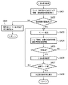
(Collation process example 1: step S108)
FIG. 17 is a flowchart showing a subroutine of step S108 (collation process).
画像形成装置101、102から排出されたシート束をコレータ103にセットしてスタートすると、ステップS301で、図10におけるリーダライタ303、304でシート上RFIDタグ内メモリのジョブ情報及び後処理固有情報を読み取り、制御部103aのメモリ(図示せず)に転送される。
When the sheet bundle discharged from the
尚、ジョブ情報及び後処理固有情報はシート束毎の共通情報であるので、シート束内のどのシートに付帯しているRFIDタグを読んでもよい。RFIDタグはひとつのリーダライタで複数のRFIDタグをまとめ読みできる特徴を有しているので、混信による読取りエラーの発生を防止することが可能である。 Since the job information and post-processing specific information are common information for each sheet bundle, an RFID tag attached to any sheet in the sheet bundle may be read. Since the RFID tag has a feature that a single reader / writer can read a plurality of RFID tags together, it is possible to prevent occurrence of a reading error due to interference.
後処理固有情報は、本例では行なった後処理の履歴情報で、その内容を図20の(c)に示す。本例の画像形成システムに備わっている後処理である「丁合い処理」801、「ステイプル処理」802、「中綴じ処理」803、「くるみ製本処理」804が終了しているかどうかを記録する。現時点では何も後処理をしていないので全ての項目が「未」である。 The post-processing specific information is history information of post-processing performed in this example, and the content thereof is shown in FIG. It is recorded whether or not “collation processing” 801, “staple processing” 802, “saddle stitching processing” 803, and “case binding processing” 804, which are post-processing provided in the image forming system of this example, are completed. Since no post-processing is performed at this time, all items are “not yet”.
ステップS302で、後処理固有情報の後処理履歴の有無801〜804と、ジョブ情報の各後処理装置の種類及び後処理の順番607(図20の(a))を照らし合わせて、これから行なおうとする後処理の種類と順序がジョブに対して適正かを判断する。本例においては、後処理情報の後処理履歴が全て「未」であり、ジョブ情報の「丁合い有無・後処理順」が"1"(丁合い処理あり、後処理順1番目)であることから、後処理情報は適正(Yes)と判断される。もし適正でない(No)と判断された場合、ステップS311で、コレータ103の操作部にエラーと、適正な後処理を表示してメインルーチンに戻る。
In step S302, the presence / absence of post-processing history 801 to 804 in post-processing specific information is compared with the types of post-processing devices in job information and the post-processing order 607 ((a) in FIG. 20). Determine whether the type and order of post-processing to be performed is appropriate for the job. In this example, the post-processing history of post-processing information is all “not yet”, and the job information “existence of collation / post-processing order” is “1” (collating processing is first, post-processing order is first). Therefore, it is determined that the post-processing information is appropriate (Yes). If it is determined that it is not appropriate (No), an error and an appropriate post-process are displayed on the operation unit of the
ステップS303で1シートを給送する。ここで、給紙トレイ301、302のいずれから次のシートを給送するかの判断は、ステップS301で読み取ったジョブ情報によりコレータ103の制御部103aが行なってもよいが、より正確にシート順序を確認するためには、ステップS303の前にリーダライタ303、304で各シートのRFIDタグから画像形成固有情報を読み取って、そのシートNo.や全シートNo.から給送順を確認することも出来る。
In step S303, one sheet is fed. Here, the
ステップS304では、図10におけるリーダライタ306でRFIDタグから画像形成固有情報を読取り制御部103aのメモリに転送する。同時にステップS305で、後処理情報中「丁合い処理」801の項目が「未」から「済み」に変えられ、リーダライタ306によりRFIDタグに書き込まれる。ステップS306で、ジョブ情報と画像形成固有情報から図10における反り補正手段307の制御方法を決定する。
In step S304, the reader /
具体的には以下の情報を元に、反り補正手段307の加圧手段(図示せず)の加圧力を制御する。
(1)画像形成固有情報の「画像形成時刻」701と現在の時刻から計算した画像形成からの経過時間、
(2)画像形成固有情報の「表面・離面平均濃度」704、
(3)ジョブ情報の「両面/片面印刷」603、
(4)ジョブ情報の「シート種類」606。
Specifically, the pressure applied by the pressurizing means (not shown) of the
(1) “Image formation time” 701 of image formation unique information and the elapsed time from image formation calculated from the current time,
(2) Image formation specific information “Surface / Separation average density” 704,
(3) “Double-sided / single-sided printing” 603 in the job information,
(4) “Sheet type” 606 of the job information.
ステップS307で反り補正手段307によって反り補正を行なう。ステップS308で丁合い処理を行なう。ステップS309でジョブの最終シートとなるまで、ステップS303〜S309を繰り返す。 In step S307, the warp correction means 307 corrects the warp. Collation processing is performed in step S308. Steps S303 to S309 are repeated until the final sheet of the job is obtained in step S309.
最終シートまで丁合いを終えたら、ステップS310で画像形成装置の操作部に動作が終了したことを表示させ、後処理の次工程を表示させ、メインルーチンS101〜S109に戻る。本例の場合は次工程がくるみ製本処理なので、その旨表示する。 When the collation to the final sheet is completed, it is displayed in step S310 that the operation has been completed on the operation unit of the image forming apparatus, the next process of post-processing is displayed, and the process returns to the main routines S101 to S109. In the case of this example, since the next process is the case binding process, this is displayed.
(くるみ製本処理例:ステップS109)
図18は、ステップS109(くるみ製本処理)のサブルーチンを示すフローチャートである。
(Case bookbinding processing example: Step S109)
FIG. 18 is a flowchart showing a subroutine of step S109 (case binding process).
コレータ103から排出されたシート束をくるみ製本機104にセットしてスタートすると、ステップS401で、図13におけるリーダライタ402でシート上のRFIDタグ内メモリのジョブ情報及び後処理固有情報を読み取り、制御部104aのメモリ(図示せず)に転送される。
When the sheet bundle discharged from the
ステップS402で、後処理固有情報の後処理履歴の有無801〜804(図20の(c))と、ジョブ情報の各後処理装置の種類及び後処理の順番607(図20の(a))を照らし合わせて、これから行なおうとする後処理の種類と順序がジョブに対して適正かを判断する。本例において現時点では後処理情報の後処理履歴の丁合い処理のみ「済み」であり、ジョブ情報の「くるみ製本有無・後処理順」が「2」(くるみ製本処理あり、後処理順2番目)であることから、後処理情報は適正(Yes)と判断される。もし適正でない(No)と判断された場合、ステップS409でくるみ製本機104の操作部にエラーと、適正な後処理を表示してメインルーチンに戻る。
In step S402, presence / absence of post-processing history information 801 to 804 (FIG. 20C), post-processing device type and
ステップS403で1シートを給送し、ステップS404で本処理が最終工程と判断し、図13におけるリーダライタ407でRFIDタグからジョブ情報・画像固有情報・後処理固有情報を削除する。ステップS405で、1シート束を給送したか否かを判定し、まだであればステップS403に戻って次のシートを給送する。1シート束を給送した場合は、ステップS406に進んでくるみ製本処理を行なう。ステップS407で、ジョブの最終シートとなるまでステップS403〜S407を繰り返す。
In step S403, one sheet is fed, and in step S404, this process is determined to be the final process, and the reader /
最終シートまでくるみ製本を終えたら、ステップS408で、画像形成装置の操作部に動作が終了したことを表示させ、後処理の次工程を表示させ、メインルーチンS101〜S109に戻る。本例の場合は本工程が最終工程なので、その旨表示する。 When the case binding to the final sheet is completed, in step S408, it is displayed on the operation unit of the image forming apparatus that the operation has been completed, the next process of post-processing is displayed, and the process returns to the main routines S101 to S109. In the case of this example, since this process is the final process, that fact is displayed.
(フィニッシャ処理例)
図19は、フィニッシャ処理のサブルーチンを示すフローチャートである。尚、本例ではフィニッシャ処理をしていない為、概略説明のみとする。
(Finisher processing example)
FIG. 19 is a flowchart showing a finisher processing subroutine. In this example, since the finisher process is not performed, only a brief description is given.
排出されたシート束をフィニッシャ105にセットしてスタートすると、ステップS501で、図14におけるリーダライタ502でシート上のRFIDタグ内メモリのジョブ情報及び後処理固有情報を読み取り、制御部105aのメモリ(図示せず)に転送される。
When the discharged sheet bundle is set in the
ステップS502で、後処理固有情報の後処理履歴の有無801〜804(図20の(c))と、ジョブ情報の各後処理装置の種類及び後処理の順番607(図20の(a))を照らし合わせて、これから行なおうとする後処理の種類と順序がジョブに対して適正かを判断する。もし適正でない(No)と判断された場合、ステップS516でフィニッシャ105の操作部にエラーと、適正な後処理を表示してメインルーチンに戻る。
In step S502, the presence / absence of post-processing history information 801 to 804 ((c) in FIG. 20), the type of each post-processing device in the job information, and the post-processing order 607 ((a) in FIG. 20). To determine whether the type and order of post-processing to be performed are appropriate for the job. If it is determined that it is not appropriate (No), an error and an appropriate post-process are displayed on the operation unit of the
ステップS503で、所望の後処理が中綴じ製本処理かステイプル処理かを判断する。ステップS504又はS510で1シートを給送し、ステップS505またはS511で本処理が最終工程と判断し、図14におけるリーダライタ507でRFIDタグからジョブ情報・画像固有情報・後処理固有情報を削除する。ステップS506又はS512で、1シート束を給送したか否かを判定し、まだであればステップS504又はS510に戻って次のシートを給送する。
In step S503, it is determined whether the desired post-processing is saddle stitch binding or stapling. In step S504 or S510, one sheet is fed. In step S505 or S511, this process is determined to be the final process, and the reader /
ステップS507又はS513で、中綴じ製本処理あるいはステイプル処理を行なう。ステップS508又はS514で、ジョブの最終シートとなるまでステップS504〜S508あるいはS510〜S514を繰り返す。 In step S507 or S513, saddle stitch bookbinding processing or stapling processing is performed. In step S508 or S514, steps S504 to S508 or S510 to S514 are repeated until the final sheet of the job is reached.
最終シートまで処理を終えたら、ステップS509又はS515で、フィニッシャの操作部に動作が終了したことを表示させ、後処理の次工程を表示させ、メインルーチンS101〜S109に戻る。 When the processing to the final sheet is completed, in step S509 or S515, the finisher operation unit displays that the operation has ended, displays the next process of post-processing, and returns to the main routines S101 to S109.
以上、プリンタで画像形成した各シートにRFIDタグを付帯する第1の動作例について説明した。かかる処理によれば、後処理がどのように複雑な工程になろうと、後処理装置で1シート単位での制御が出来るので、正確なシート管理が可能となる。 The first operation example in which the RFID tag is attached to each sheet image-formed by the printer has been described above. According to such processing, no matter how complicated the post-processing is, the post-processing apparatus can perform control in units of one sheet, so that accurate sheet management is possible.
<本実施形態の画像形成システムの第2の動作例>
以下、本発明に係る画像形成システムの第2の動作例について説明を行なう。本動作例を実現する画像形成システムの構成と動作の基本的な部分は第1の動作例と同様であるので、共通部分の説明は省略し、特徴的な部分のみ説明する。
本動作例は、第1の動作例がプリントするシート全てにRFIDタグを付帯させるのに対し、選択的に付帯させることを特徴とする。その為の構成は第1の動作例と同じであり、図15に示すシステム全体の動作のフローチャートのうち、ステップS107(画像形成・RFIDタグ付帯処理)及びステップS108(丁合い処理)のサブルーチンが異なる。
<Second Operation Example of Image Forming System of Present Embodiment>
The second operation example of the image forming system according to the present invention will be described below. Since the basic configuration of the configuration and operation of the image forming system that realizes this operation example is the same as that of the first operation example, description of common parts is omitted, and only characteristic parts are described.
This operation example is characterized in that the RFID tag is attached to all the sheets to be printed in the first operation example, but is selectively attached. The configuration for this is the same as in the first operation example. In the flowchart of the entire system operation shown in FIG. 15, the subroutines of step S107 (image forming / RFID tag supplementary processing) and step S108 (collation processing) are performed. Different.
第2の動作例では、実際に反り補正をしなければならないシートが、シートの大部分に高濃度の画像が印刷され、かつシート種類が薄紙のように腰が弱いものであり、一般的にはこれらの条件を満たすシートは少ない為、大半のシートは反り補正を必要としないことを考慮し、反り補正を必要とするシートにだけにRFIDタグを付帯させることで、少量のRFIDタグの使用で本願発明の効果を得る。 In the second operation example, a sheet that actually needs to be warped is printed with a high density image on the most part of the sheet, and the sheet type is weak like a thin paper. Since there are few sheets that satisfy these conditions, considering that most sheets do not require warpage correction, a small amount of RFID tags can be used by attaching RFID tags only to sheets that require warpage correction. Thus, the effect of the present invention is obtained.
以下、ステップS107(画像形成・RFIDタグ付帯処理)、ステップS108(丁合い処理)について、その詳細動作を図22及び図23を用いて説明する。 The detailed operation of step S107 (image formation / RFID tag supplementary processing) and step S108 (collation processing) will be described below with reference to FIGS.
(画像形成・RFIDタグ付帯処理例2:ステップS107)
図22は、ステップS107(画像形成・RFIDタグ付帯処理)のサブルーチンを示すフローチャートである。
(Image formation / RFID tag attached processing example 2: step S107)
FIG. 22 is a flowchart showing a subroutine of step S107 (image formation / RFID tag attachment processing).
ステップS601で、各プリンタの制御部101a、102a内のメモリ内のジョブ情報から本ジョブにおける各プリンタでのデータの印刷順を決定し、ステップS602で、1枚目の画像形成を行なう。ステップS603で、前記メモリ内に画像形成固有情報を作成する。
In step S601, the printing order of the data in each printer in this job is determined from the job information in the memory in the
ステップS604で、以下のジョブ情報と画像形成固有情報を元にそのシートの反り量を予測し、予測値が所定量を超えたものについてステップS605でRFIDタグを付帯する。
(1)画像形成固有情報の「表面・離面平均濃度」704、
(2)ジョブ情報の「両面/片面印刷」603、
(3)ジョブ情報の「シート種類」606。
In step S604, the warpage amount of the sheet is predicted based on the following job information and image formation unique information, and an RFID tag is attached in step S605 for a case where the predicted value exceeds a predetermined amount.
(1) Image formation specific information “Surface / Separation average density” 704,
(2) “Double-sided / single-sided printing” 603 in job information,
(3) “Sheet type” 606 of the job information.
ステップS604で、反り量予測値が所定量以下の場合はRFIDタグを付帯せずステップS607に飛ぶ。ステップS606で、各プリンタの制御部101a、102a内のメモリ内のジョブ情報及び画像形成固有情報をリーダライタ202によってRFIDタグ106内メモリに書き込む。ステップS607でジョブの最終シートとなるまでステップS602〜S607を繰り返す。
In step S604, if the predicted warpage amount is equal to or less than the predetermined amount, the RFID tag is not attached and the process jumps to step S607. In step S606, job information and image formation unique information in the memories in the
最終シートまで処理を終えたら、ステップS608で、本ジョブ中のRFIDタグを付帯させた実績があれば画像形成装置の操作部に動作が終了したことを表示させ、後処理の次工程を表示させ、メインルーチンS101〜S109に戻る。もし本ジョブ中にRFIDタグを付帯させた実績がひとつもない場合は、ステップS610でこの最終シートにRFIDタグを付帯させ、ジョブ情報を書きこんだ後、ステップS609に戻って画像形成装置の操作部に動作が終了したことを表示させ、後処理の次工程を表示させ、メインルーチンS101〜S109に戻る。これによって排出されたシート束の中にはRFIDタグが必ず1つ含まれ、次工程への情報伝達が可能となる。 When processing to the final sheet is completed, in step S608, if there is a track record of attaching the RFID tag in this job, the operation unit of the image forming apparatus is displayed to indicate that the operation has been completed, and the next process of post-processing is displayed. Return to the main routines S101 to S109. If there is no record of attaching RFID tags to this job, attach RFID tags to this final sheet in step S610, write job information, and then return to step S609 to operate the image forming apparatus. Display that the operation has been completed, display the next step of post-processing, and return to the main routines S101 to S109. As a result, one RFID tag is always included in the discharged sheet bundle, and information can be transmitted to the next process.
(丁合い処理例2:ステップS108)
図23は、ステップS108(丁合い処理)のサブルーチンを示すフローチャートである。
(Collation process example 2: step S108)
FIG. 23 is a flowchart showing a subroutine of step S108 (collation process).
画像形成装置101、102から排出されたシート束をコレータ103にセットしてスタートすると、ステップS701で、図10におけるリーダライタ303、304でシート上のRFIDタグ内メモリのジョブ情報及び後処理固有情報を読み取り、制御部103aのメモリ(図示せず)に転送される。
When the sheet bundle discharged from the
尚、ジョブ情報及び後処理固有情報はシート束毎の共通情報であるので、シート束内のどのシートに付帯しているRFIDタグを読んでもよい。RFIDタグはひとつのリーダライタで複数のRFIDタグをまとめ読みできる特徴を有しているので、混信による読取りエラーの発生を防止することが可能である。 Since the job information and post-processing specific information are common information for each sheet bundle, an RFID tag attached to any sheet in the sheet bundle may be read. Since the RFID tag has a feature that a single reader / writer can read a plurality of RFID tags together, it is possible to prevent occurrence of a reading error due to interference.
後処理固有情報は、本例では行なった後処理の履歴情報で、その内容を図20の(c)に示す。 The post-processing specific information is history information of post-processing performed in this example, and the content thereof is shown in FIG.
ステップS702で後処理固有情報の後処理履歴の有無801〜804と、ジョブ情報の各後処理装置の種類及び後処理の順番607(図17の(a))を照らし合わせて、これから行なおうとする後処理の種類と順序がジョブに対して適正かを判断する。もし適正でない(No)と判断された場合、ステップS712でコレータ103の操作部にエラーと、適正な後処理を表示してメインルーチンに戻る。
In step S702, the presence / absence of post-processing history information 801 to 804 in the post-processing specific information is compared with the type of each post-processing device and the post-processing order 607 ((a) in FIG. 17) of the job information. It is determined whether the type and order of post-processing to be performed are appropriate for the job. If it is determined that it is not appropriate (No), an error and an appropriate post-process are displayed on the operation unit of the
ステップS703で1シートを給送する。尚、本例での給送における給紙トレイ301、302の選択は、ステップS701で読み取られたジョブ情報に基づき、コレータ103の制御部103aにより行われる。
In step S703, one sheet is fed. Note that the selection of the
ステップS704で、図10におけるリーダライタ306でシートにRFIDタグが付帯しているかを判断する。RFIDタグを付帯している場合、ステップS705で画像固有情報を読取り制御部103aのメモリに転送する。同時にステップS706で、後処理情報中「丁合い処理」801の項目が「未」から「済み」に変えられ、リーダライタ306によりRFIDタグに書き込まれる。
In step S704, the reader /
ステップS707で、ジョブ情報と画像形成固有情報から図10における反り補正手段307の制御方法を決定する。具体的には以下の情報を元に、反り補正手段307の加圧手段(図示せず)の加圧力を制御する。
(1)画像形成固有情報の「画像形成時刻」701と現在の時刻から計算した画像形成からの経過時間、
(2)画像形成固有情報の「表面・離面平均濃度」704、
(3)ジョブ情報の「両面/片面印刷」603、
(4)ジョブ情報の「シート種類」606。
In step S707, the control method of the
(1) “Image formation time” 701 of image formation unique information and the elapsed time from image formation calculated from the current time,
(2) Image formation specific information “Surface / Separation average density” 704,
(3) “Double-sided / single-sided printing” 603 in the job information,
(4) “Sheet type” 606 of the job information.
ステップS708で、反り補正手段307によって反り補正を行なう。
In step S708, the
一方、RFIDタグを付帯していないシートに関しては、ステップS704からステップS709に飛び、反り補正は行なわない。 On the other hand, for a sheet not attached with an RFID tag, the process jumps from step S704 to step S709 and no warp correction is performed.
ステップS709で丁合い処理を行なう。ステップS710でジョブの最終シートとなるまでステップS703〜S710を繰り返す。 In step S709, collation processing is performed. Steps S703 to S710 are repeated until the final sheet of the job is reached in step S710.
最終シートまで丁合いを終えたら、ステップS311で画像形成装置の操作部に動作が終了したことを表示させ、後処理の次工程を表示させ、メインルーチンS101〜S109に戻る
本第2の動作例においては、シートのコストと比較してそのコストが無視できないRFIDタグのシートへの添付を最小限に抑えることが可能なので、低コストのオンデマンド印刷が実現できる。
When the collation to the final sheet is completed, in step S311, the operation unit of the image forming apparatus is displayed to indicate that the operation has been completed, the next process of the post-processing is displayed, and the process returns to the main routines S101 to S109. Since it is possible to minimize the attachment of RFID tags to a sheet whose cost cannot be ignored compared to the cost of the sheet, low-cost on-demand printing can be realized.
<他の動作例及び構成例>
上記第1の動作例では画像形成した全シートにRFIDタグを付帯する例が示され、第2の動作例では反り補正が必要なシートあるいは反り補正が必要なシートが無い場合の最後のシートにRFIDタグを付帯する例が示された。しかしながら、この第1の動作例と第2の動作例との間に、RFIDタグのコストとRFIDタグによるシート管理の正確さや融通性とを考慮して、種々の動作例が考えられる。例えば、RFIDタグを製本後の本の管理に使用するのであれば、各本の最初及び/又は最後のシートにはRFIDタグを付けることも考えられる。同様の処理は、製本された各本が1巻〜n巻のような関係を持つ場合にも有効である。更に、複数の製本単位にRFIDタグを有するダミーシートを挿入して、製本の梱包の管理をすることも可能である。本発明は、かかる用途も含むものである。
<Other operation examples and configuration examples>
In the first operation example, an example in which an RFID tag is attached to all sheets formed with an image is shown. In the second operation example, the last sheet when there is no sheet that needs to be warped or no sheet that needs to be warped. An example of attaching an RFID tag was shown. However, various operation examples are conceivable between the first operation example and the second operation example in consideration of the cost of the RFID tag and the accuracy and flexibility of sheet management by the RFID tag. For example, if an RFID tag is used for book management after bookbinding, it may be possible to attach an RFID tag to the first and / or last sheet of each book. The same processing is also effective when each book that has been bound has a relationship such as 1 to n volumes. Furthermore, it is possible to manage the packaging of bookbinding by inserting dummy sheets having RFID tags into a plurality of bookbinding units. The present invention includes such applications.
又、上記実施形態では、RFIDタグ付帯装置201-1、201-2はプリンタ101、102のシート搬送方向下流側に設けていたが、RFIDが耐熱性、耐圧性が十分あれば、給送装置の下流に設けても良い。
In the above embodiment, the RFID tag-attached devices 201-1 and 201-2 are provided on the downstream side in the sheet conveying direction of the
また、予めRFIDタグが付帯されたシートを給紙装置にセットしても良い。 In addition, a sheet with an RFID tag attached in advance may be set in the sheet feeding device.
又、図1に破線で示したネットワーク100bのように、コンピュータ100で後処理装置を含むシステム全体を統一的に管理することも可能であり、前述のようにこの場合には、更に、コンピュータ100から各後処理装置の制御部103a〜105aを制御するプログラムをそのシステム仕様に対応してダウンロードするように構成すれば、コンピュータ100から例えば、上記第1の動作例と第2の動作例とを容易に切り替えられるシステムが構築される。
Further, as in the
又、上記実施形態では、処理中のエラーとして工程の手順が正常でない場合のみを記載したが、例えば、必要なシートが無いあるいは余分なシートが有るなどのエラーなどもあり、本実施形態のフローチャートにそれらを組み込むのはRFIDタグの内容を見れば容易に成し得るものである。 In the above embodiment, only the case where the procedure of the process is not normal is described as an error during processing. However, for example, there is an error that there is no necessary sheet or there is an extra sheet. It is easy to incorporate them into the RFID tag by looking at the contents of the RFID tag.
又、上記実施形態では、プリンタ、コレータ、くるみ製本機、簡易製本用のフィニッシャなどを独立した装置で示したが、これらの複数が一体となった装置であってもよい。すなわち、本発明は、複数の機器(例えばホストコンピュータ、インタフェース機器、プリンタなど)から構成されるシステムあるいは統合装置に適用しても、ひとつの機器からなる装置に適用してもよい。 In the above embodiment, a printer, a collator, a case binding machine, a simple bookbinding finisher, and the like are shown as independent devices. However, a plurality of these devices may be integrated. In other words, the present invention may be applied to a system or an integrated device composed of a plurality of devices (for example, a host computer, an interface device, a printer, etc.) or an apparatus composed of a single device.
又、本発明の目的は、前述した実施形態の機能を実現するソフトウェアのプログラムコードを記録した記憶媒体(または記録媒体)を、システムあるいは装置に供給し、そのシステムあるいは装置のコンピュータ(またはCPUやMPU)が記憶媒体に格納されたプログラムコードを読み出し実行することによっても、達成されることは言うまでもない。この場合、記憶媒体から読み出されたプログラムコード自体が前述した実施形態の機能を実現することになり、そのプログラムコードを記憶した記憶媒体は本発明を構成することになる。又、コンピュータが読み出したプログラムコードを実行することにより、前述した実施形態の機能が実現されるだけでなく、そのプログラムコードの指示に基づき、コンピュータ上で稼働しているオペレーティングシステム(OS)などが実際の処理の一部または全部を行い、その処理によって前述した実施形態の機能が実現される場合も含まれることは言うまでもない。 Another object of the present invention is to supply a storage medium (or recording medium) in which a program code of software for realizing the functions of the above-described embodiments is recorded to a system or apparatus, and to perform a computer (or CPU or CPU) of the system or apparatus. Needless to say, this can also be achieved by the MPU) reading and executing the program code stored in the storage medium. In this case, the program code itself read from the storage medium realizes the functions of the above-described embodiments, and the storage medium storing the program code constitutes the present invention. Further, by executing the program code read by the computer, not only the functions of the above-described embodiments are realized, but also an operating system (OS) running on the computer based on the instruction of the program code. It goes without saying that a case where the function of the above-described embodiment is realized by performing part or all of the actual processing and the processing is included.
さらに、記憶媒体から読み出されたプログラムコードが、コンピュータに挿入された機能拡張カードやコンピュータに接続された機能拡張ユニットに備わるメモリに書込まれた後、そのプログラムコードの指示に基づき、その機能拡張カードや機能拡張ユニットに備わるCPUなどが実際の処理の一部または全部を行い、その処理によって前述した実施形態の機能が実現される場合も含まれることは言うまでもない。 Furthermore, after the program code read from the storage medium is written into a memory provided in a function expansion card inserted into the computer or a function expansion unit connected to the computer, the function is determined based on the instruction of the program code. It goes without saying that the CPU or the like provided in the expansion card or the function expansion unit performs part or all of the actual processing and the functions of the above-described embodiments are realized by the processing.
本発明を上記記憶媒体に適用する場合、その記憶媒体には、先に説明したフローチャートに対応するプログラムコードが格納されることになる。 When the present invention is applied to the storage medium, the storage medium stores program codes corresponding to the flowcharts described above.
100 コンピュータ
101 カラープリンタ
102 モノクロプリンタ
103 コレータ
104 くるみ製本機
105 フィニッシャ
201 RFIDタグ付帯装置
202 タグ貼付け器
203 リーダライタ
100 computers
101 color printer
102 Monochrome printer
103 Collator
104 Perfect binding machine
105 Finisher
201 RFID tag equipment
202 tag applicator
203 Reader / Writer
Claims (7)
前記RFIDタグから前記属性情報を読み取る読取手段と、前記読み取られた属性情報に基づいて前記記録媒体の後処理を制御する制御手段と、前記記録媒体に付帯したRFIDタグに後処理が完了したことを示す履歴情報を含む後処理固有情報を前記属性情報として付加する書込手段と、を有する少なくとも1つの後処理装置と、
を有することを特徴とする画像形成システム。 Image forming means for forming an image on a recording medium based on job information including post-processing and discharging the recording medium, and an image set in accordance with at least the job information and the image formation on the discharged recording medium At least one image forming apparatus having an RFID tag attached means for attaching an RFID tag in which attribute information including formation unique information is written;
Reading means for reading the attribute information from the RFID tag, control means for controlling post-processing of the recording medium based on the read attribute information, and post-processing for the RFID tag attached to the recording medium is completed Writing means for adding post-processing specific information including history information indicating as attribute information, and at least one post-processing device ,
An image forming system comprising:
前記RFIDタグから前記属性情報を読み取る読取手段と、前記読み取られた属性情報に基づいて前記記録媒体の後処理を制御する制御手段とを有する少なくとも1つの後処理装置とを有し、
前記RFIDタグ付帯手段は、前記ジョブ情報と前記画像形成固有情報とに基づいて記録媒体の反り量を予測し、前記予測値が所定の反り量を超えた記録媒体に前記RFIDタグを付帯させることを特徴とする画像形成システム。 Image forming means for forming an image on a recording medium based on job information including post-processing and discharging the recording medium, and an image set in accordance with at least the job information and the image formation on the discharged recording medium At least one image forming apparatus having an RFID tag attached means for attaching an RFID tag in which attribute information including formation unique information is written;
Wherein possess a reading means from the RFID tag reading the attribute information, and at least one post-processing apparatus and a control means for controlling the post-processing of the recording medium based on the read attribute information,
The RFID tag attachment means predicts a warp amount of a recording medium based on the job information and the image formation unique information, and attaches the RFID tag to a recording medium whose predicted value exceeds a predetermined warp amount. An image forming system.
前記読み取られた属性情報に基づいて前記記録媒体の後処理を制御する制御手段と、
前記制御手段に制御される、RFIDタグを付帯する前記記録媒体を供給するトレイと、所定数の前記記録媒体毎に製本処理をする製本手段と、製本処理が終了すると前記RFIDタグの内容を消去する消去手段と、
を有することを特徴とする後処理装置。 Reading means for reading attribute information including job information including post-processing and image formation specific information set in accordance with image formation from an RFID tag attached to the image-formed recording medium;
Control means for controlling post-processing of the recording medium based on the read attribute information ;
The tray for supplying the recording medium attached with the RFID tag controlled by the control means, the bookbinding means for performing the bookbinding processing for each predetermined number of the recording media, and erasing the contents of the RFID tag when the bookbinding processing is completed. Erasing means to perform,
A post-processing apparatus comprising:
Priority Applications (3)
| Application Number | Priority Date | Filing Date | Title |
|---|---|---|---|
| JP2005156198A JP4817719B2 (en) | 2005-05-27 | 2005-05-27 | Image forming system and post-processing apparatus |
| US11/438,626 US7195171B2 (en) | 2005-05-27 | 2006-05-22 | Image forming method and system |
| US11/674,073 US7837114B2 (en) | 2005-05-27 | 2007-02-12 | Image forming method and system |
Applications Claiming Priority (1)
| Application Number | Priority Date | Filing Date | Title |
|---|---|---|---|
| JP2005156198A JP4817719B2 (en) | 2005-05-27 | 2005-05-27 | Image forming system and post-processing apparatus |
Publications (3)
| Publication Number | Publication Date |
|---|---|
| JP2006327104A JP2006327104A (en) | 2006-12-07 |
| JP2006327104A5 JP2006327104A5 (en) | 2008-07-10 |
| JP4817719B2 true JP4817719B2 (en) | 2011-11-16 |
Family
ID=37462126
Family Applications (1)
| Application Number | Title | Priority Date | Filing Date |
|---|---|---|---|
| JP2005156198A Expired - Fee Related JP4817719B2 (en) | 2005-05-27 | 2005-05-27 | Image forming system and post-processing apparatus |
Country Status (2)
| Country | Link |
|---|---|
| US (2) | US7195171B2 (en) |
| JP (1) | JP4817719B2 (en) |
Families Citing this family (8)
| Publication number | Priority date | Publication date | Assignee | Title |
|---|---|---|---|---|
| JP4817719B2 (en) * | 2005-05-27 | 2011-11-16 | キヤノン株式会社 | Image forming system and post-processing apparatus |
| US8064089B2 (en) * | 2006-10-04 | 2011-11-22 | Xerox Corporation | Automatic indexing of printed documents |
| WO2008109115A2 (en) * | 2007-03-06 | 2008-09-12 | Dnp Photo Imaging America Corp. | Automatic device detection and configuration in a network-aware print fulfillment engine |
| US8089650B2 (en) * | 2007-04-25 | 2012-01-03 | Xerox Corporation | Connected offline finishing devices |
| US7859412B2 (en) * | 2008-06-16 | 2010-12-28 | Xerox Corporation | System and method of monitoring modules of printing machines utilizing RFID tags |
| US20090314836A1 (en) * | 2008-06-18 | 2009-12-24 | Xerox Corporation | Automatic print job tracking |
| JP5067348B2 (en) * | 2008-11-12 | 2012-11-07 | ブラザー工業株式会社 | Image forming apparatus |
| US20100245892A1 (en) * | 2009-03-31 | 2010-09-30 | Konica Minolta Systems Laboratory, Inc. | Printing Method for Screen Image |
Family Cites Families (14)
| Publication number | Priority date | Publication date | Assignee | Title |
|---|---|---|---|---|
| JPS59121070A (en) * | 1982-12-28 | 1984-07-12 | Ricoh Co Ltd | Copying device |
| EP0461671B1 (en) * | 1990-06-15 | 2000-02-02 | Canon Kabushiki Kaisha | Image forming apparatus |
| JP3581441B2 (en) * | 1995-07-20 | 2004-10-27 | キヤノン株式会社 | Image forming device |
| JP3255056B2 (en) * | 1996-12-20 | 2002-02-12 | 富士ゼロックス株式会社 | Distributed processing booklet creation system |
| JP3695030B2 (en) | 1997-01-14 | 2005-09-14 | 富士ゼロックス株式会社 | Image recording system with post-processing device |
| JP3912031B2 (en) * | 2001-05-15 | 2007-05-09 | 株式会社デンソーウェーブ | Copy machines and facsimile machines |
| US7048194B2 (en) * | 2002-03-27 | 2006-05-23 | Seiko Epson Corporation | Printing paper with memory element mounted thereon and printing technique using such printing paper |
| JP4088875B2 (en) * | 2002-08-28 | 2008-05-21 | 富士ゼロックス株式会社 | Image forming system and method |
| US7463388B2 (en) * | 2003-05-29 | 2008-12-09 | Canon Kabushiki Kaisha | Image forming apparatus with control of image formation using read information |
| JP2005031153A (en) * | 2003-07-07 | 2005-02-03 | Canon Inc | Image forming apparatus and its control method |
| JP2005053077A (en) * | 2003-08-04 | 2005-03-03 | Canon Inc | Image formation device and controlling method in the device |
| JP2005222372A (en) * | 2004-02-06 | 2005-08-18 | Ricoh Co Ltd | Printed document management method, printed document management program, image forming apparatus, and printed document management system |
| JP2006095886A (en) * | 2004-09-29 | 2006-04-13 | Canon Inc | Image forming device and its method |
| JP4817719B2 (en) * | 2005-05-27 | 2011-11-16 | キヤノン株式会社 | Image forming system and post-processing apparatus |
-
2005
- 2005-05-27 JP JP2005156198A patent/JP4817719B2/en not_active Expired - Fee Related
-
2006
- 2006-05-22 US US11/438,626 patent/US7195171B2/en not_active Expired - Fee Related
-
2007
- 2007-02-12 US US11/674,073 patent/US7837114B2/en not_active Expired - Fee Related
Also Published As
| Publication number | Publication date |
|---|---|
| US20070131776A1 (en) | 2007-06-14 |
| US20060266818A1 (en) | 2006-11-30 |
| US7837114B2 (en) | 2010-11-23 |
| US7195171B2 (en) | 2007-03-27 |
| JP2006327104A (en) | 2006-12-07 |
Similar Documents
| Publication | Publication Date | Title |
|---|---|---|
| JP4817719B2 (en) | Image forming system and post-processing apparatus | |
| KR100524568B1 (en) | Printing control apparatus and display method therefor | |
| KR101239522B1 (en) | Printing control apparatus and information processing apparatus and method for controlling a printing apparatus and method for controlling an information processing apparatus and computer-readable storage medium | |
| EP1577099B1 (en) | Image forming apparatus, image processing method, program and recording medium | |
| JP5178386B2 (en) | Job control apparatus, job control method, and computer program | |
| US8493603B2 (en) | Printing apparatus printing method for controlling to stop executing print job and storage medium storing program thereof | |
| EP1264709A1 (en) | Printing system | |
| US10220610B2 (en) | Method of printing a print job with digital finishing visualization images | |
| US20090122341A1 (en) | Information processing apparatus, information processing method, and program | |
| JP2008265336A (en) | Bookbinding finishing method and bookbinding finishing device | |
| EP1980406B1 (en) | Image forming apparatus | |
| JPWO2002074547A1 (en) | Printing apparatus, printing method, and computer-readable storage medium | |
| JPH10151734A (en) | Back cover data printing apparatus | |
| US6144818A (en) | Image forming apparatus having a finishing section including improved stapling function | |
| JP2006268358A (en) | Information processor and control method therefor | |
| US20100195157A1 (en) | Image forming apparatus and image forming method of the image forming apparatus | |
| US20190073170A1 (en) | Print control device, print control method, and recording medium having print control program recorded thereon | |
| JP2001031326A (en) | Printer control device, method therefor and image processing system | |
| EP2324415B1 (en) | Information processing apparatus, image forming system, control method, program, and storage medium | |
| CN115079527A (en) | Image forming apparatus with a toner supply device | |
| JP2005329588A (en) | Image forming apparatus system | |
| JP2022175123A (en) | Printing system, print control device and controlling method thereof, and program | |
| JP4589033B2 (en) | Recording apparatus, recording method, storage medium, program | |
| JP2009037552A (en) | Recording unit and control method therefor | |
| JP2005104041A (en) | Image processor, image processing method, recording medium readable by computer, and program |
Legal Events
| Date | Code | Title | Description |
|---|---|---|---|
| A521 | Request for written amendment filed |
Free format text: JAPANESE INTERMEDIATE CODE: A523 Effective date: 20080527 |
|
| A621 | Written request for application examination |
Free format text: JAPANESE INTERMEDIATE CODE: A621 Effective date: 20080527 |
|
| A977 | Report on retrieval |
Free format text: JAPANESE INTERMEDIATE CODE: A971007 Effective date: 20101021 |
|
| A131 | Notification of reasons for refusal |
Free format text: JAPANESE INTERMEDIATE CODE: A131 Effective date: 20110124 |
|
| TRDD | Decision of grant or rejection written | ||
| A01 | Written decision to grant a patent or to grant a registration (utility model) |
Free format text: JAPANESE INTERMEDIATE CODE: A01 Effective date: 20110826 |
|
| A01 | Written decision to grant a patent or to grant a registration (utility model) |
Free format text: JAPANESE INTERMEDIATE CODE: A01 |
|
| A61 | First payment of annual fees (during grant procedure) |
Free format text: JAPANESE INTERMEDIATE CODE: A61 Effective date: 20110830 |
|
| FPAY | Renewal fee payment (event date is renewal date of database) |
Free format text: PAYMENT UNTIL: 20140909 Year of fee payment: 3 |
|
| FPAY | Renewal fee payment (event date is renewal date of database) |
Free format text: PAYMENT UNTIL: 20140909 Year of fee payment: 3 |
|
| LAPS | Cancellation because of no payment of annual fees |