JP4816537B2 - Heat storage device - Google Patents
Heat storage device Download PDFInfo
- Publication number
- JP4816537B2 JP4816537B2 JP2007083739A JP2007083739A JP4816537B2 JP 4816537 B2 JP4816537 B2 JP 4816537B2 JP 2007083739 A JP2007083739 A JP 2007083739A JP 2007083739 A JP2007083739 A JP 2007083739A JP 4816537 B2 JP4816537 B2 JP 4816537B2
- Authority
- JP
- Japan
- Prior art keywords
- heat storage
- heat
- storage means
- heat transfer
- latent
- Prior art date
- Legal status (The legal status is an assumption and is not a legal conclusion. Google has not performed a legal analysis and makes no representation as to the accuracy of the status listed.)
- Active
Links
Images

Classifications
-
- F—MECHANICAL ENGINEERING; LIGHTING; HEATING; WEAPONS; BLASTING
- F28—HEAT EXCHANGE IN GENERAL
- F28D—HEAT-EXCHANGE APPARATUS, NOT PROVIDED FOR IN ANOTHER SUBCLASS, IN WHICH THE HEAT-EXCHANGE MEDIA DO NOT COME INTO DIRECT CONTACT
- F28D20/00—Heat storage plants or apparatus in general; Regenerative heat-exchange apparatus not covered by groups F28D17/00 or F28D19/00
- F28D20/02—Heat storage plants or apparatus in general; Regenerative heat-exchange apparatus not covered by groups F28D17/00 or F28D19/00 using latent heat
-
- Y—GENERAL TAGGING OF NEW TECHNOLOGICAL DEVELOPMENTS; GENERAL TAGGING OF CROSS-SECTIONAL TECHNOLOGIES SPANNING OVER SEVERAL SECTIONS OF THE IPC; TECHNICAL SUBJECTS COVERED BY FORMER USPC CROSS-REFERENCE ART COLLECTIONS [XRACs] AND DIGESTS
- Y02—TECHNOLOGIES OR APPLICATIONS FOR MITIGATION OR ADAPTATION AGAINST CLIMATE CHANGE
- Y02E—REDUCTION OF GREENHOUSE GAS [GHG] EMISSIONS, RELATED TO ENERGY GENERATION, TRANSMISSION OR DISTRIBUTION
- Y02E60/00—Enabling technologies; Technologies with a potential or indirect contribution to GHG emissions mitigation
- Y02E60/14—Thermal energy storage
Description
本発明は、潜熱蓄熱剤を搭載した蓄熱装置に関するものである。 The present invention relates to a heat storage device equipped with a latent heat storage agent.
蓄熱を行う方法として、非蓄熱時には固体となり、蓄熱時には液体となる潜熱蓄熱剤の相変化を利用した蓄熱装置は良く知られており、この潜熱蓄熱剤をカプセル状の容器内に充填した蓄熱カプセルと被加熱流体を熱交換させることにより、蓄熱・放熱を行う装置はすでに実用化されている。 As a method of performing heat storage, a heat storage device using a phase change of a latent heat storage agent that becomes a solid when not storing heat and becomes a liquid when storing heat is well known, and a heat storage capsule in which this latent heat storage agent is filled in a capsule-like container Devices that store and release heat by exchanging heat with the fluid to be heated have already been put into practical use.
ここで、カプセル状の容器に潜熱蓄熱剤を充填した場合、熱交換を行う伝熱面との間の
熱抵抗が大きくなる可能性があり、また容器の占める体積が大きくなる傾向となるため、体積当たりの潜熱蓄熱剤の充填量が減少するという課題があった。
Here, when the capsule-shaped container is filled with the latent heat storage agent, there is a possibility that the thermal resistance between the heat transfer surface that performs heat exchange may increase, and the volume occupied by the container tends to increase. There was a problem that the filling amount of the latent heat storage agent per volume decreased.
この課題を解決するため、潜熱蓄熱剤を、薄いアルミラミネートフィルムにより成型された袋に充填し、真空パックするようにした蓄熱装置が提案されている(例えば、特許文献1参照)。
しかしながら、上記特許文献1に記載された従来の蓄熱装置は、アルミラミネートフィルムにより構成されているため、潜熱蓄熱剤が融解及び凝固し、体積が膨張及び収縮した際に潜熱蓄熱剤が重力の影響で下部に移動し、下部は、潜熱蓄熱剤が過度に集中した結果膨らみ、上部には、潜熱蓄熱剤の移動の結果として空間が生じることとなり、熱の授受性能が悪化するという課題があった。 However, since the conventional heat storage device described in Patent Document 1 is composed of an aluminum laminate film, the latent heat storage agent is affected by gravity when the latent heat storage agent melts and solidifies, and the volume expands and contracts. The lower part swells as a result of excessive concentration of the latent heat storage agent, and the upper part has a problem that a space is generated as a result of the movement of the latent heat storage agent, which deteriorates heat transfer performance. .
本発明は、前記従来の課題を解決するもので、潜熱蓄熱剤の融解・凝固による移動の影響を少なくし、安定した熱の授受を行うことができる蓄熱装置を提供することを目的とする。 An object of the present invention is to solve the above-described conventional problems, and to provide a heat storage device that can reduce the influence of movement due to melting and solidification of a latent heat storage agent and perform stable heat transfer.
前記従来の課題を解決するために、本発明の蓄熱装置は、平板状に成型され、非蓄熱時には固体となり、蓄熱時には液体となる潜熱蓄熱剤を、アルミラミネートフィルム製の袋にて真空パックを施して形成した蓄熱手段と、前記蓄熱手段を挟み込むように保持すると共に、前記潜熱蓄熱剤に対して熱の授受を行い、一定間隔で凹凸を有する伝熱壁と、前記伝熱壁を通じて前記蓄熱手段を加熱または冷却するための流体が流れる流体通路と、前記蓄熱手段及び前記伝熱壁の周囲に配設された断熱手段とを備え、前記蓄熱手段を略水平方向に配設するとともに、前記アルミラミネートフィルム製の袋の表面に折り曲げ部を形成し、前記伝熱壁の凹部に対向させ、前記アルミラミネートフィルム製の袋の折り曲げ部を配置する構成としたことを特徴とするもので、潜熱蓄熱剤が融解・凝固を繰り返した際においても、潜熱蓄熱剤の厚さを一定に保つことができ、伝熱壁と効果的に熱の授受を行うことができ、安定した蓄放熱性能を維持することができる。 In order to solve the above-described conventional problems, the heat storage device of the present invention is formed into a flat plate shape, becomes a solid when not storing heat, and becomes a liquid when storing heat, and a vacuum pack in a bag made of aluminum laminate film. a heat storage means formed by subjecting holds so as to sandwich said heat storage means, have rows exchanges heat to the latent heat storage agent, a heat transfer wall having an uneven at regular intervals, the through the heat transfer thermal wall A fluid passage through which a fluid for heating or cooling the heat storage means flows, and a heat insulating means disposed around the heat storage means and the heat transfer wall, the heat storage means being disposed in a substantially horizontal direction , wherein the aluminum laminate film of the bent portion is formed on the surface of the bag, it said is opposed to the recess of the heat transfer hot wall, and configured to arrange the bent portion of the bag made of the aluminum laminate film Therefore, even when the latent heat storage agent is repeatedly melted and solidified, the thickness of the latent heat storage agent can be kept constant, and heat can be effectively exchanged with the heat transfer wall. The heat storage / heat dissipation performance can be maintained.
本発明の蓄熱装置は、繰り返し使用した際においても蓄熱性能及び放熱性能を悪化させることなく一定に保つことが可能であり、潜熱蓄熱剤を用いた蓄熱装置の信頼性を向上させることができる。 Even when the heat storage device of the present invention is used repeatedly, it can be kept constant without deteriorating the heat storage performance and the heat dissipation performance, and the reliability of the heat storage device using the latent heat storage agent can be improved.
第1の発明は、平板状に成型され、非蓄熱時には固体となり、蓄熱時には液体となる潜熱蓄熱剤を、アルミラミネートフィルム製の袋にて真空パックを施して形成した蓄熱手段と、前記蓄熱手段を挟み込むように保持すると共に、前記潜熱蓄熱剤に対して熱の授受を行い、一定間隔で凹凸を有する伝熱壁と、前記伝熱壁を通じて前記蓄熱手段を加熱または冷却するための流体が流れる流体通路と、前記蓄熱手段及び前記伝熱壁の周囲に配設された断熱手段とを備え、前記蓄熱手段を略水平方向に配設するとともに、前記アルミラミネートフィルム製の袋の表面に折り曲げ部を形成し、前記伝熱壁の凹部に対向させ、前記アルミラミネートフィルム製の袋の折り曲げ部を配置する構成としたことを特徴とするもので、潜熱蓄熱剤が融解・凝固を繰り返した際においても、潜熱蓄熱剤の厚さを一定に保つことができ、伝熱壁と効果的に熱の授受を行うことができ、安定した蓄放熱性能を維持することができる。 According to a first aspect of the present invention, there is provided a heat storage means formed by applying a vacuum pack with a bag made of an aluminum laminate film, a latent heat storage agent that is molded into a flat plate shape and becomes a solid when not storing heat and becomes a liquid when storing heat, and the heat storing means the holds so as to sandwich said have rows exchanging heat to the latent heat storage agent, a heat transfer wall having an uneven at regular intervals, a fluid for heating or cooling the thermal storage means through said heat transfer thermal wall A fluid passage that flows, and heat insulating means disposed around the heat storage means and the heat transfer wall, and the heat storage means is disposed in a substantially horizontal direction and is folded on the surface of the bag made of the aluminum laminate film. part is formed, said to face the concave portion of the heat transfer hot wall, that it has a construction of arranging the bent portion of the bag made of the aluminum laminate film in which the characteristic feature of the latent heat storage agent melting and solidification Ri even when returned, it is possible to maintain the thickness of the latent heat storage agent constant, the heat transfer wall and effectively can transmit and receive heat, it is possible to maintain a stable heat storage and release performance.
また、伝熱壁に、一定間隔で凹凸を設けたもので、潜熱蓄熱剤と伝熱壁との接触面積を増やすと共に、伝熱壁を通じて蓄熱手段と熱交換を行う流体通路の耐圧性能を向上させることができる。 In addition, the heat transfer wall is provided with irregularities at regular intervals, increasing the contact area between the latent heat storage agent and the heat transfer wall, and improving the pressure resistance performance of the fluid passage that exchanges heat with the heat storage means through the heat transfer wall. Can be made.
また、袋の表面に、一定間隔で規則的に折り曲げ加工を施したもので、伝熱壁と蓄熱手段との密着性を高め、熱の授受性能を向上させることができる。 Further, the bag surface is regularly bent at regular intervals, so that the adhesion between the heat transfer wall and the heat storage means can be improved and the heat transfer performance can be improved.
第2の発明は、特に、第1の発明の潜熱蓄熱剤の主成分を、酢酸ナトリウム三水和物としたもので、高効率な蓄熱性能及び放熱性能を実現することができる。 In the second invention, in particular, the main component of the latent heat storage agent of the first invention is sodium acetate trihydrate, so that highly efficient heat storage performance and heat dissipation performance can be realized.
以下、本発明の実施の形態について、図面を参照しながら説明する。なお、本実施の形態によって本発明が限定されるものではない。 Hereinafter, embodiments of the present invention will be described with reference to the drawings. Note that the present invention is not limited to the present embodiment.
(実施の形態1)
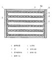
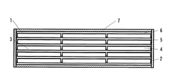
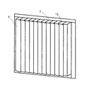
図1は、本発明の実施の形態1における蓄熱装置の正面断面図、図2は、同蓄熱装置の側面断面図、図3は、同蓄熱装置を用いた給湯機の構成図、図4は、同蓄熱手段の斜視図である。
(Embodiment 1)
1 is a front cross-sectional view of a heat storage device according to Embodiment 1 of the present invention, FIG. 2 is a side cross-sectional view of the heat storage device, FIG. 3 is a configuration diagram of a water heater using the heat storage device, and FIG. It is a perspective view of the heat storage means.
図1〜4において、本実施の形態における蓄熱装置1は、大きくアルミラミネートフィルム製の袋2に真空パックされ平板状に成型された潜熱蓄熱剤3を封入した蓄熱手段4と、蓄熱手段4を、両側から挟み込むような構造で保持し蓄熱手段4に対して熱の授受を行うための伝熱壁5と、2枚の伝熱壁5内部に空間が設けられ、蓄熱手段4を加熱または冷却するための流体(例えば、水)が流れる流体通路6と、蓄熱手段4、伝熱壁5及び流体通路6から外部への熱リークを防止するためのウレタンフォームまたはウレタンスラブ等により構成された断熱手段7から構成されている。8は、蓄熱装置1の蓄熱手段4に蓄熱を行うための湯を加熱する加熱手段である。
1 to 4, a heat storage device 1 according to the present embodiment includes a heat storage means 4 that encloses a latent
本実施の形態では、蓄熱手段4の寸法は、取り扱い及び持ち運びが容易である幅200mm、高さ200mm、厚さ20mmの寸法に成型されており、蓄熱手段4内に封入されている潜熱蓄熱剤3は、現在一般家庭で使用されている貯湯タンク(図示せず)を有した給湯機(図示せず)の貯湯温度と同等温度である60℃前後に融点を有する、主成分が酢酸ナトリウム三水和物で構成されているものを使用している。 In the present embodiment, the heat storage means 4 is shaped to have a width of 200 mm, a height of 200 mm, and a thickness of 20 mm that is easy to handle and carry, and the latent heat storage agent enclosed in the heat storage means 4. 3 has a melting point around 60 ° C., which is the same temperature as the hot water storage temperature (not shown) of a hot water storage tank (not shown) currently used in ordinary households, and the main component is sodium acetate. The one composed of hydrate is used.
潜熱蓄熱剤3を密封しているアルミラミネートフィルム製の袋2の表面には、伝熱壁5の凹凸5aの凹部に合わせて一定間隔で折り曲げ加工がされており、潜熱蓄熱剤3が融解し体積が膨張した際に、この部分に潜熱蓄熱剤3を送り込むことで充填可能量を増やすことができる。伝熱壁5は、2枚の銅板を、はんだ付けまたはロウ付けにより接着、貼り合わせて形成されている。
The surface of the aluminum
2枚の銅板の間には、水または湯が流れる流体通路6が形成されているが、単位体積当たりの蓄熱剤充填量を大きくするために、銅板の板厚は0.3〜0.5mm程度のものを使用しており、そのままでは、水道圧をかけると変形してしまう恐れがあるため、一定間隔で凹凸を設け、凹部をはんだ付けまたはロウ付けにより接着することで耐圧性能を向上させている。
A
流体通路6には、蓄熱時には湯、放熱時には水が流される。蓄熱時に利用される湯は、加熱手段8によって常温の水から65〜80℃程度の湯に昇温される。加熱手段8は、ボイラーや電気ヒーター等でも勿論問題ないが、近年の省エネルギー化の流れを考えるとヒートポンプによる加熱がエネルギー効率も優れており望ましい。蓄熱手段4、伝熱壁5及
び流体通路6は、外部との温度差が大きくこのままでは外部への熱リークによって蓄熱性能の悪化が予想されるため、グラスウール・発泡スチロール又は硬質ウレタンスラブ等によって構成された断熱手段7によって外部との熱の出入りが遮断される。
Hot water flows through the
この蓄熱装置1を、一般家庭の給湯用に用いる場合、家庭環境、設置スペース等にもよるが、潜熱蓄熱剤3の必要量は、100〜300kg程度になるため、上記の寸法の蓄熱手段4が90〜270個程度必要となる。
When this heat storage device 1 is used for hot water supply in general households, the required amount of the latent
この数量の蓄熱手段4を一定のスペースに設置するため、蓄熱手段4と伝熱壁5及び流体通路6は、略水平方向に積層する構造によって省スペース化を図っている。まず底面に、内部に流体通路6を有した伝熱壁5が設置され、その上に一定数量の蓄熱手段4が並べられる。その上にさらに、伝熱壁5、その上に蓄熱手段4というような構造により、無駄な空間を有することなく一定体積に最大限潜熱蓄熱剤3を充填することができる。
In order to install this quantity of heat storage means 4 in a fixed space, the heat storage means 4, the
この蓄熱装置1を用いた給湯機の作用を、以下に説明する。 The operation of the water heater using this heat storage device 1 will be described below.
蓄熱運転を行う場合、流体通路6に、加熱手段8で加熱された高温の湯が循環ポンプ9を通じて流され、潜熱蓄熱剤3に蓄熱を行う。潜熱蓄熱剤3の温度が、湯の温度に対して低い場合は、湯が有する熱は伝熱壁5を通じて潜熱蓄熱剤3に移動する。潜熱蓄熱剤3は温度が上昇するにつれて、固体から液体へと相変化を行い、潜熱領域の蓄熱を行うが、融解すると体積が膨張するため、液化した潜熱蓄熱剤3は、空間を有している伝熱壁5の凹部に流れていくが、このときアルミラミネートフィルム製の袋2に設けている折り込み部10が、潜熱蓄熱剤3とともに伝熱壁5側に押されていき、伝熱壁5と蓄熱手段4の密着性を向上させ、熱伝導性をさらに向上させることができる。この動作を連続して行うと、酢酸ナトリウム三水和物系の潜熱蓄熱剤3の場合、融点が約60℃であるため、この温度を上回ると蓄熱完了である。
When performing the heat storage operation, hot water heated by the heating means 8 is passed through the
蓄熱が完了すると、必要時に所定の温度の湯を使用することができる。湯を使用するため蛇口(図示せず)等が開けられた場合、水道から供給された水は、伝熱壁5を通じて蓄熱手段4内の潜熱蓄熱剤3と熱交換することにより加熱され、その後、混合弁11により水と混合され所定の温度に調整された後、利用系に送られ風呂、シャワー等に使用される。潜熱蓄熱剤3が有する熱が、充分に利用され放熱されると、潜熱蓄熱剤3が、液体から固体へと相変化を行う。潜熱蓄熱剤3は相変化により凝固すると体積が減少するため、蓄熱手段4と上部の伝熱壁5との間に一定の間隔で空間が生じる。
When heat storage is completed, hot water at a predetermined temperature can be used when necessary. When a faucet (not shown) or the like is opened to use hot water, the water supplied from the water supply is heated by exchanging heat with the latent
再度蓄熱運転を行うと、潜熱蓄熱剤3は再び融解し体積が膨張するため上部の伝熱壁5と接触する。現在までの検討結果によると、蓄熱運転の際には、1枚の伝熱壁5で片面から蓄熱を行う場合と2枚の伝熱壁5を用いて両面から蓄熱を行う場合とで性能差はほとんどないことが確認されている。
When the heat storage operation is performed again, the latent
放熱運転の場合は、1枚の伝熱壁5で片面から放熱を行う場合に比べて2枚の伝熱壁5で両面から放熱を行う場合の方が放熱性能が優れているため、理想的な状態で、体積吸収ができると共に上部から潜熱蓄熱剤3等に加重が加わっているため、融解時の潜熱蓄熱剤3の過度の体積膨張による変形等を防止することができる。
In the case of heat dissipation operation, the heat dissipation performance is better when heat is dissipated from both sides with two
なお、本実施の形態に示した各種材料や数値などは、必ずしもこれに限定されるものではなく、所定の役割を果たすことができるならば別の材料や数値で何ら問題はない。 Note that the various materials and numerical values shown in this embodiment are not necessarily limited to these, and there is no problem with other materials and numerical values as long as they can play a predetermined role.
以上のように、本発明にかかる蓄熱装置は、潜熱蓄熱剤と伝熱壁との間の熱の授受性能
を、繰り返し使用した際においても、悪化させることなく一定に保つことができるため、液体等の流動性を持つ物質を用いた熱交換装置全般に利用可能である。
As described above, the heat storage device according to the present invention can maintain a constant heat transfer performance between the latent heat storage agent and the heat transfer wall without deteriorating even when repeatedly used. It can be used for all heat exchange devices using materials with fluidity.
1 蓄熱装置
2 袋
3 潜熱蓄熱剤
4 蓄熱手段
5 伝熱壁
6 流体通路
7 断熱手段
DESCRIPTION OF SYMBOLS 1
Claims (2)
Priority Applications (1)
| Application Number | Priority Date | Filing Date | Title |
|---|---|---|---|
| JP2007083739A JP4816537B2 (en) | 2007-03-28 | 2007-03-28 | Heat storage device |
Applications Claiming Priority (1)
| Application Number | Priority Date | Filing Date | Title |
|---|---|---|---|
| JP2007083739A JP4816537B2 (en) | 2007-03-28 | 2007-03-28 | Heat storage device |
Publications (2)
| Publication Number | Publication Date |
|---|---|
| JP2008241174A JP2008241174A (en) | 2008-10-09 |
| JP4816537B2 true JP4816537B2 (en) | 2011-11-16 |
Family
ID=39912739
Family Applications (1)
| Application Number | Title | Priority Date | Filing Date |
|---|---|---|---|
| JP2007083739A Active JP4816537B2 (en) | 2007-03-28 | 2007-03-28 | Heat storage device |
Country Status (1)
| Country | Link |
|---|---|
| JP (1) | JP4816537B2 (en) |
Cited By (1)
| Publication number | Priority date | Publication date | Assignee | Title |
|---|---|---|---|---|
| WO2014167798A1 (en) | 2013-04-10 | 2014-10-16 | パナソニック株式会社 | Heat storage device |
Families Citing this family (10)
| Publication number | Priority date | Publication date | Assignee | Title |
|---|---|---|---|---|
| JP2010121814A (en) * | 2008-11-18 | 2010-06-03 | Panasonic Corp | Heat storage device |
| JP2010203691A (en) * | 2009-03-04 | 2010-09-16 | Panasonic Corp | Heat storage device and water heater using the same |
| JP2013088049A (en) * | 2011-10-19 | 2013-05-13 | Mitsubishi Plastics Inc | Latent heat storage tank and hot water supply system |
| JP2013088050A (en) * | 2011-10-19 | 2013-05-13 | Mitsubishi Plastics Inc | Latent heat storage tank and hot water supply system |
| KR20160053602A (en) | 2014-11-05 | 2016-05-13 | 현대자동차주식회사 | Latent heat storage module and apprartus for latent heat storage |
| DE102015203477A1 (en) * | 2015-02-26 | 2016-09-01 | Siemens Aktiengesellschaft | Process for producing a latent heat storage |
| JP2016211770A (en) * | 2015-05-06 | 2016-12-15 | 株式会社アクアノエル | Heat exchange body, heat exchange unit and air conditioning system |
| JP2017161192A (en) * | 2016-03-11 | 2017-09-14 | パナソニックIpマネジメント株式会社 | Heat storage device and hot water generation device |
| BE1024319B1 (en) * | 2016-06-30 | 2018-01-30 | Probalco Bvba | Double-walled crockery with a pouch filled with phase-transition material |
| JP6962754B2 (en) * | 2016-09-14 | 2021-11-05 | 永大産業株式会社 | Floor structure with heat storage unit and heat storage unit |
Family Cites Families (6)
| Publication number | Priority date | Publication date | Assignee | Title |
|---|---|---|---|---|
| NL7811008A (en) * | 1978-11-06 | 1980-05-08 | Akzo Nv | DEVICE FOR STORING HEAT. |
| JPS6055094U (en) * | 1983-09-22 | 1985-04-17 | 松下電器産業株式会社 | Regenerative electric heater |
| JPS619485A (en) * | 1984-06-22 | 1986-01-17 | Matsushita Electric Ind Co Ltd | Production of theral energy storage element |
| JP2003240454A (en) * | 2002-02-13 | 2003-08-27 | Ebara Corp | Plate heat exchanger and absorption refrigerator using it |
| JP4239491B2 (en) * | 2002-07-02 | 2009-03-18 | ダイキン工業株式会社 | Assembly method of heat storage unit |
| JP2006189170A (en) * | 2004-12-28 | 2006-07-20 | Toyota Motor Corp | Heat accumulator |
-
2007
- 2007-03-28 JP JP2007083739A patent/JP4816537B2/en active Active
Cited By (3)
| Publication number | Priority date | Publication date | Assignee | Title |
|---|---|---|---|---|
| WO2014167798A1 (en) | 2013-04-10 | 2014-10-16 | パナソニック株式会社 | Heat storage device |
| JPWO2014167798A1 (en) * | 2013-04-10 | 2017-02-16 | パナソニックIpマネジメント株式会社 | Heat storage device |
| US10337805B2 (en) | 2013-04-10 | 2019-07-02 | Panasonic Intellectual Property Management Co., Ltd. | Heat storage device |
Also Published As
| Publication number | Publication date |
|---|---|
| JP2008241174A (en) | 2008-10-09 |
Similar Documents
| Publication | Publication Date | Title |
|---|---|---|
| JP4816537B2 (en) | Heat storage device | |
| CN106856230B (en) | battery module | |
| KR20130062918A (en) | Molten salt battery device and temperature control method for molten salt battery | |
| JP2009186056A (en) | Heat storage container | |
| JP2014026825A (en) | Battery cooler | |
| CN102635948A (en) | Combination type heat storage water tank of external disk heat storage casting box and condensation heat exchanger | |
| JP2012215323A (en) | Latent heat accumulator | |
| CN201811625U (en) | Phase change heat storage exchange module and device and system thereof | |
| JP2009097746A (en) | Heat storage device | |
| US20050281547A1 (en) | Surface heating system | |
| GB2143025A (en) | Chemical phase change heat or cold stores | |
| JP2005315462A (en) | Heat storage type radiation air conditioning panel | |
| CN101368748A (en) | Phase-change heat-storage electrical heater | |
| CN218033357U (en) | Heat insulation and conduction contact switch and heat storage heater | |
| JP2013088050A (en) | Latent heat storage tank and hot water supply system | |
| JP5487231B2 (en) | Latent heat storage building material and manufacturing method thereof | |
| JP6889615B2 (en) | Asphalt pavement solution heating / heat retention device for curing accelerator | |
| JP5755963B2 (en) | Thermal storage water heater | |
| JP2013088049A (en) | Latent heat storage tank and hot water supply system | |
| JPH0875185A (en) | Heat storage apparatus | |
| EP0148889A1 (en) | Chemical phase change heat stores | |
| JP2002106962A (en) | Heat storage vessel and bathroom heat supply apparatus using the same | |
| JP2009109167A (en) | Heat storage device | |
| CN212511814U (en) | Phase-change heat storage type water heater | |
| CN216146632U (en) | Novel integrated liquid cooling box type temperature control device |
Legal Events
| Date | Code | Title | Description |
|---|---|---|---|
| A621 | Written request for application examination |
Free format text: JAPANESE INTERMEDIATE CODE: A621 Effective date: 20090701 |
|
| RD01 | Notification of change of attorney |
Free format text: JAPANESE INTERMEDIATE CODE: A7421 Effective date: 20090817 |
|
| A977 | Report on retrieval |
Free format text: JAPANESE INTERMEDIATE CODE: A971007 Effective date: 20110526 |
|
| A131 | Notification of reasons for refusal |
Free format text: JAPANESE INTERMEDIATE CODE: A131 Effective date: 20110607 |
|
| A521 | Written amendment |
Free format text: JAPANESE INTERMEDIATE CODE: A523 Effective date: 20110706 |
|
| TRDD | Decision of grant or rejection written | ||
| A01 | Written decision to grant a patent or to grant a registration (utility model) |
Free format text: JAPANESE INTERMEDIATE CODE: A01 Effective date: 20110802 |
|
| A01 | Written decision to grant a patent or to grant a registration (utility model) |
Free format text: JAPANESE INTERMEDIATE CODE: A01 |
|
| A61 | First payment of annual fees (during grant procedure) |
Free format text: JAPANESE INTERMEDIATE CODE: A61 Effective date: 20110815 |
|
| FPAY | Renewal fee payment (event date is renewal date of database) |
Free format text: PAYMENT UNTIL: 20140909 Year of fee payment: 3 |
|
| R151 | Written notification of patent or utility model registration |
Ref document number: 4816537 Country of ref document: JP Free format text: JAPANESE INTERMEDIATE CODE: R151 |
|
| FPAY | Renewal fee payment (event date is renewal date of database) |
Free format text: PAYMENT UNTIL: 20140909 Year of fee payment: 3 |