JP4816331B2 - Suction cup device - Google Patents
Suction cup device Download PDFInfo
- Publication number
- JP4816331B2 JP4816331B2 JP2006230132A JP2006230132A JP4816331B2 JP 4816331 B2 JP4816331 B2 JP 4816331B2 JP 2006230132 A JP2006230132 A JP 2006230132A JP 2006230132 A JP2006230132 A JP 2006230132A JP 4816331 B2 JP4816331 B2 JP 4816331B2
- Authority
- JP
- Japan
- Prior art keywords
- suction cup
- attracted
- suction
- central
- accessory mounting
- Prior art date
- Legal status (The legal status is an assumption and is not a legal conclusion. Google has not performed a legal analysis and makes no representation as to the accuracy of the status listed.)
- Expired - Fee Related
Links
Images


Description
本発明は吸盤装置に関する。 The present invention relates to a suction cup device.
壁面や自動車のダッシュボードなどに物品を取り付ける吸盤装置が提案されている。
この種の吸盤装置は、吸盤と、吸盤の背面の中央部から突設された中心軸と、吸盤の背面の外周部に当接可能な押圧部材と、吸盤の吸着面が被吸着面に吸着した状態で押圧部材を背面の外周部に押圧させる方向に付勢すると共に吸盤の中央部を被吸着面から離れる方向に付勢する付勢機構とを備えている。
そして、吸盤を被吸着面に吸着させた後、付勢機構により吸盤の中央部を被吸着面から離間させ、がたつくことなく安定した状態で吸盤装置を被吸着面に吸着させるようにしている。
従来、押圧部材は吸盤を覆う単一の部材で形成されている(特許文献1参照)。
This type of suction cup device has a suction cup, a central shaft projecting from the center of the back of the suction cup, a pressing member that can contact the outer periphery of the back of the suction cup, and the suction surface of the suction cup to the suction surface. And an urging mechanism that urges the pressing member in a direction to press the outer peripheral portion of the back surface and urges the central portion of the suction cup in a direction away from the attracted surface.
Then, after the suction cup is attracted to the attracted surface, the central portion of the sucker is separated from the attracted surface by the urging mechanism, and the sucker device is attracted to the attracted surface in a stable state without rattling.
Conventionally, the pressing member is formed of a single member that covers the suction cup (see Patent Document 1).
そのため、被吸着面が湾曲面である場合、押圧部材が吸盤の外周全周に当接できず、したがって、吸盤の中央部を被吸着面から離間させる方向に変位しがたく、吸盤装置を被吸着面に安定した状態で取り付けにくい不具合があった。
本発明はこのような事情に鑑みなされたものであり、その目的は、被吸着面が湾曲面である場合であっても、がたつくことなく安定した状態で被吸着面に取り付ける上で有利な吸盤装置を提供することにある。
Therefore, when the attracted surface is a curved surface, the pressing member cannot contact the entire outer periphery of the suction cup, and therefore, the suction member is not easily displaced in the direction of separating the central portion of the suction cup from the attracted surface. There was a problem that it was difficult to install in a stable state on the suction surface.
The present invention has been made in view of such circumstances, and an object of the present invention is to provide a suction cup that is advantageous for mounting on a suction surface in a stable state without rattling even when the suction surface is a curved surface. To provide an apparatus.
上述の目的を達成するため、本発明は、厚さ方向の一方の面が吸着面とされ他方の面が背面とされた吸盤と、前記吸盤の背面の中央部から前記厚さ方向に沿って前記背面から離れる方向に突設された中心軸と、前記中心軸の先端に連結されたアクセサリー取付部と、前記吸盤と前記アクセサリー取付部との間で前記中心軸に組み付けられ前記吸盤の背面の外周部に当接可能な押圧部材と、前記アクセサリー取付部と前記押圧部材との間に設けられ前記吸着面が前記被吸着面に吸着した状態で前記押圧部材を前記背面の外周部に押圧させる方向に付勢すると共に前記吸盤の中央部を前記被吸着面から離れる方向に付勢する付勢機構とを備えた吸盤装置であって、前記押圧部材は、前記吸盤の背面と前記アクセサリー取付部との間で前記吸盤の直径方向に沿って延在しその延在方向の中央部に前記中心軸が移動可能に挿通されその延在方向の両端が前記背面の外周部にそれぞれ当接する第1部材と、前記第1部材と前記アクセサリー取付部との間で前記第1部材の延在方向と交差する方向でかつ前記吸盤の直径方向に沿って延在しその延在方向の中央部に前記中心軸が移動可能に挿通されその延在方向の両端が前記背面の外周部にそれぞれ当接する第2部材とを含んで構成されており、前記付勢機構は、前記中心軸と、前記中心軸に巻装されて前記第1部材の延在方向の中央部と前記第2部材の延在方向の中央部との間に設けられ前記第1部材の延在方向の中央部と前記第2部材の延在方向の中央部とを離す方向に付勢する第1コイルスプリングと、前記中心軸に巻装されて前記第2部材の延在方向の中央部と前記アクセサリー取付部との間に設けられ前記第2部材の延在方向の中央部と前記アクセサリー取付部とを離す方向に付勢する第2コイルスプリングとを含んで構成されていることを特徴とする。
また、本発明は、厚さ方向の一方の面が吸着面とされ他方の面が背面とされた吸盤と、前記吸盤の背面の中央部から前記厚さ方向に沿って前記背面から離れる方向に突設された中心軸と、前記中心軸の先端に連結されたアクセサリー取付部と、前記吸盤と前記アクセサリー取付部との間で前記中心軸に組み付けられ被吸着面に前記吸着面が吸着した際に前記吸着面が吸着した前記被吸着面箇所の外側の前記被吸着面箇所に当接可能な押圧部材と、前記アクセサリー取付部と前記押圧部材との間に設けられ前記吸着面が前記被吸着面に吸着した状態で前記押圧部材を前記吸着面が吸着した前記被吸着面箇所の外側の前記被吸着面箇所に押圧させる方向に付勢すると共に前記吸盤の中央部を前記被吸着面から離れる方向に付勢する付勢機構とを備えた吸盤装置であって、前記押圧部材は、前記吸盤の背面と前記アクセサリー取付部との間で前記吸盤の直径方向に沿って延在しその延在方向の中央部に前記中心軸が移動可能に挿通されその延在方向の両端が、前記吸着面が前記被吸着面に吸着した状態で前記吸着面が吸着した前記被吸着面箇所の外側の前記被吸着面箇所に当接する第1部材と、前記第1部材と前記アクセサリー取付部との間で前記第1部材の延在方向と交差する方向でかつ前記吸盤の直径方向に沿って延在しその延在方向の中央部に前記中心軸が移動可能に挿通されその延在方向の両端が、前記吸着面が前記被吸着面に吸着した状態で前記吸着面が吸着した前記被吸着面箇所の外側の前記被吸着面箇所に当接する第2部材とを含んで構成されており、前記付勢機構は、前記中心軸と、前記中心軸に巻装されて前記第1部材の延在方向の中央部と前記第2部材の延在方向の中央部との間に設けられ前記第1部材の延在方向の中央部と前記第2部材の延在方向の中央部とを離す方向に付勢する第1コイルスプリングと、前記中心軸に巻装されて前記第2部材の延在方向の中央部と前記アクセサリー取付部との間に設けられ前記第2部材の延在方向の中央部と前記アクセサリー取付部とを離す方向に付勢する第2コイルスプリングとを含んで構成されていることを特徴とする。
In order to achieve the above-described object, the present invention provides a suction cup in which one surface in the thickness direction is an adsorption surface and the other surface is a back surface, and a central portion of the back surface of the suction cup along the thickness direction. A central shaft projecting in a direction away from the back surface, an accessory mounting portion connected to a tip of the central shaft, and the back surface of the suction cup assembled to the central shaft between the suction cup and the accessory mounting portion A pressing member capable of contacting an outer peripheral portion, and provided between the accessory mounting portion and the pressing member, presses the pressing member against the outer peripheral portion of the back surface in a state where the suction surface is attracted to the attracted surface. And a biasing mechanism that biases the central portion of the suction cup in a direction away from the attracted surface, wherein the pressing member includes a back surface of the suction cup and the accessory mounting portion. Between the suction cups and A first member extending along the direction, the central axis is movably inserted in a central portion of the extending direction, and both ends of the extending direction are in contact with the outer peripheral portion of the back surface, and the first member, It extends along the diameter direction of the suction cup in a direction intersecting the extending direction of the first member with the accessory mounting portion, and the central axis is movably inserted through a central portion in the extending direction. The both ends of the extending direction are configured to include second members that respectively contact the outer peripheral portion of the back surface, and the urging mechanism is wound around the central axis and the central axis so as to be wound on the first axis. A central portion in the extending direction of the first member and a central portion in the extending direction of the second member provided between a central portion in the extending direction of the member and a central portion in the extending direction of the second member; A first coil spring urging in a direction to release the second coil spring and the second part wound around the central shaft A second coil spring that is provided between a central portion in the extending direction of the second member and the accessory attaching portion and biases the second member in the direction in which the central portion in the extending direction of the second member is separated from the accessory attaching portion. It is configured .
Further, the present invention is a suction cup in which one surface in the thickness direction is an adsorption surface and the other surface is a back surface, and in a direction away from the back surface along the thickness direction from the center of the back surface of the suction cup. When the suction surface is adsorbed to the attracted surface assembled to the central axis between the projecting central shaft, the accessory mounting portion connected to the tip of the central shaft, and the suction cup and the accessory mounting portion A suction member that can abut on the attracted surface portion outside the attracted surface portion to which the attracting surface is attracted, and the suction surface provided between the accessory mounting portion and the press member. The suction member is urged in a direction to press the pressing member against the attracted surface portion outside the attracted surface portion adsorbed by the attracting surface and the central portion of the suction cup is separated from the attracted surface. With a biasing mechanism that biases in the direction A was suction cup devices, the pressing member, the central axis in the central portion of the extending direction thereof extends along the diameter direction of the suction cup in between the rear and the accessory attaching portion of the suction cup is movable A first member that is inserted into the suction surface and has both ends extending in contact with the attracted surface portion outside the attracted surface portion to which the attracted surface is attracted while the attracted surface is attracted to the attracted surface; The central axis extends between the first member and the accessory mounting portion in a direction intersecting the extending direction of the first member and along the diameter direction of the suction cup, and in the central portion of the extending direction. Is inserted in a movable manner, and both ends in the extending direction are in contact with the attracted surface portion outside the attracted surface portion where the attracted surface is attracted in a state where the attracted surface is attracted to the attracted surface. 2 members, and the biasing mechanism A central axis, and wound between the central axis and provided between a central portion in the extending direction of the first member and a central portion in the extending direction of the second member, in the extending direction of the first member. A first coil spring that biases the central portion in a direction separating the central portion in the extending direction of the second member; a central portion in the extending direction of the second member that is wound around the central shaft; and the accessory And a second coil spring provided between the mounting portion and biasing in a direction to separate the accessory mounting portion from a central portion in the extending direction of the second member .
本発明によれば、押圧部材が、中心軸に別々に組み付けられ吸盤の背面の外周部の周方向に異なった箇所に当接する互いに切り離された複数の部材により構成されているので、あるいは、押圧部材が、中心軸に別々に組み付けられ吸着面が吸着した被吸着面箇所の外側の被吸着面箇所で吸盤の外周部の周方向に異なった箇所に当接する互いに切り離された複数の部材により構成されているので、被吸着面が湾曲面である場合であっても、複数の部材により吸盤の外周部を被吸着面の湾曲形状に追従させて押圧でき、したがって安定した状態で吸盤の中央部を被吸着面から離す方向に変位でき、吸盤装置を被吸着面にがたつくことがなく確実に取り付ける上で有利となる。 According to the present invention, the pressing member is composed of a plurality of members separated from each other that are separately assembled to the central axis and come into contact with different locations in the circumferential direction of the outer peripheral portion of the back surface of the suction cup. The member is composed of a plurality of members separated from each other that come into contact with different locations in the circumferential direction of the outer peripheral portion of the suction cup at the location of the suction surface outside the location of the suction surface where the suction surface is attracted by being separately assembled on the central axis Therefore, even if the attracted surface is a curved surface, the outer peripheral portion of the suction cup can be pressed by following the curved shape of the attracted surface by a plurality of members, so that the central portion of the sucker is stable. Can be displaced in a direction away from the surface to be attracted, which is advantageous in securely mounting the suction cup device without rattling on the surface to be attracted.
(第1の実施の形態)
次に、本発明の実施の形態について図面を参照して説明する。
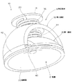
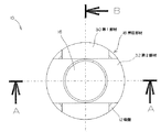
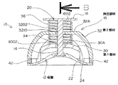
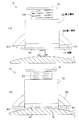
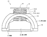
図1は第1の実施の形態の吸盤装置10の斜視図、図2は吸盤装置10の平面図、図3は図2のAA線断面図、図4は図2のBB線断面図である。
図1に示す吸盤装置10は、例えば、自動車の車室内のダッシュボード上でカーナビゲーション装置やテレビジョン装置のディスプレイパネルを支持し、また、種々の車載機器をリモートコントロールするためのコントローラーなどを支持するものである。
図1乃至図4に示すように、第1の実施の形態に係る吸盤装置10は、吸盤12、中心軸14、アクセサリー取付部16、押圧部材18、付勢機構20などを含んで構成されている。
(First embodiment)
Next, embodiments of the present invention will be described with reference to the drawings.
1 is a perspective view of the
The
As shown in FIGS. 1 to 4, the
吸盤12は、図1乃至図4に示すように、円盤状を呈し、厚さ方向の一方の面が凹状の吸着面22とされ他方の面が凸状の背面24とされている。
吸盤12は、弾性を有する合成樹脂材料、例えば、ウレタン系やスチレン系、シリコン樹脂系など、従来の吸盤12に用いられている従来公知の様々な材料が使用可能である。
なお、図面では省略しているが、吸盤12の外縁に吸盤12の径方向外方向に延在する取り外し操作用の片体が設けられている。
また、吸盤12として従来公知の様々な構成が採用可能であり、例えば、図9に示すように、吸盤12を、背面24を構成する円盤状の吸盤本体26と、吸着面22を構成するゲル層28とを含んで構成するようにしてもよい。
吸盤本体26は、前記の吸盤12と同様に、弾性を有する合成樹脂材料、例えば、ウレタン系やスチレン系、シリコン樹脂系など、従来の吸盤12に用いられている従来公知の様々な材料が使用可能である。
ゲル層28はゲルからなり、背面24と反対に位置する吸盤本体26の面に凹状の取り付け面2602が形成され、この取り付け面2602に該取り付け面2602を覆うように接合され、吸着面22はこのゲル層28の表面で形成されている。
このようなゲルとして、ポリエチレン系、スチレン系、シリコン樹脂系などの合成樹脂系のゲルが使用可能であり、ポリエチレン系のゲルとして、例えば、市販品である株式会社コスモ計器の商品名「コスモゲル」を使用可能である。スチレン系のゲルとして、例えば、市販品である株式会社イノアックコーポレーションの商品名「NAGFLEX」を使用可能である。シリコン系のゲルとして、例えば、市販品である株式会社ジェルテックの商品名「αGEL」(アルファゲル)を使用可能である。
また、取り付け面2602へのゲル層28の接合は、例えば、二色成形や接着剤による接合などの方法が採用可能である。
ゲル層28により吸着面22を構成すると、被吸着面2が皮シボ面として形成され、あるいは、こまかな凹凸面で形成され、あるいは、ざらざらな面で形成されている場合であっても、吸着面22は凹凸に追従して変形し、凹凸面との間に隙間を介在させずに凹凸面やざらざらな面に吸着面22を密着でき、吸盤12を凹凸面やざらざらな面に確実に吸着させることができ、種々の物品を、ダッシュボードパネルの皮シボ面などの被吸着面2に確実に取り付ける上で有利となる。
As shown in FIGS. 1 to 4, the
For the
In addition, although omitted in the drawings, a piece for removal operation that extends in the radially outward direction of the
Various conventionally known configurations can be adopted as the
As with the
The gel layer 28 is made of gel, and a
As such a gel, a polyethylene-based, styrene-based, or silicone-based synthetic resin-based gel can be used. As a polyethylene-based gel, for example, the commercial name of Cosmo Keiki Co., Ltd. Can be used. As the styrenic gel, for example, a commercially available product name “NAGFLEX” of INOAC CORPORATION can be used. As the silicon-based gel, for example, a commercially available product name “αGEL” (alpha gel) of Geltech Co., Ltd. can be used.
In addition, for example, a method such as two-color molding or bonding using an adhesive can be employed for bonding the gel layer 28 to the
When the
中心軸14は、図1乃至図4に示すように、吸盤12の背面24の中央部から吸盤12の厚さ方向に沿って(吸着面22の中心軸14に沿って)背面24から離れる方向に突設されている。
中心軸14は金属製または硬質な合成樹脂から形成され、中心軸14の下端は吸盤12の中央部に埋め込まれている。
As shown in FIGS. 1 to 4, the
The
アクセサリー取付部16は、中心軸14の先端に取着され、本実施の形態では、アクセサリー取付部16は円形の板状を呈し、アクセサリー取付部16の中心に中心軸14が連結されている。したがって、本実施の形態では、中心軸14の先端が連結されたアクセサリー取付部16の箇所は、図3、図4に示すように、中心軸14に直交する平面1602となっている。
アクセサリー取付部16は、中心軸14と同様に、金属製または硬質な合成樹脂から形成され、本実施の形態では中心軸14とアクセサリー取付部16は一体に形成されている。
アクセサリー取付部16には、例えば、カーナビゲーション装置やテレビジョン装置のディスプレイパネルや、また、種々の車載機器をリモートコントロールするためのコントローラーなどが着脱可能に取着される。
The
The
For example, a display panel of a car navigation device or a television device, a controller for remotely controlling various in-vehicle devices, or the like is detachably attached to the
押圧部材18は、吸盤12の背面24の外周部に当接可能に設けられている。
押圧部材18は、中心軸14に別々に組み付けられ吸盤12の背面24の外周部の周方向に異なった箇所に当接する互いに切り離された複数の部材により構成されている。
本実施の形態では、複数の部材は、第1部材30と第2部材32との2つの部材であり、それら第1、第2部材30、32は硬質な合成樹脂から形成され、共に板状を呈している。
第1部材30は、吸盤12の背面24とアクセサリー取付部16との間の中間の箇所で、後述する第1、第2コイルスプリング34、36の外径よりも大きい幅で吸盤12の直径方向に沿って延在しその延在方向の中央部に中心軸14が移動可能に挿通されその延在方向の両端が背面24の外周部にそれぞれ当接可能に形成されている。
より詳細には、第1部材30は、延在方向の中央部が延在方向の両端よりも吸盤12から離れる方向に変位した湾曲した板状を呈している。
そして、第1部材30の延在方向の中央部に孔3002が形成され、中心軸14はこの孔3002に軸方向に移動可能に挿通されている。
第2部材32は、第1部材30とアクセサリー取付部16との間の箇所で、後述する第1、第2コイルスプリング34、36の外径よりも大きい幅で第1部材30の延在方向と直交する方向でかつ吸盤12の直径方向に沿って延在しその延在方向の中央部に中心軸14が移動可能に挿通されその延在方向の両端が背面24の外周部にそれぞれ当接可能に形成されている。
より詳細には、第2部材32は、延在方向の中央部が延在方向の両端よりも吸盤12から離れる方向に変位した湾曲した板状を呈している。
そして、第2部材32の延在方向の中央部に孔3202が形成され、中心軸14はこの孔3202に軸方向に移動可能に挿通されている。
The pressing
The
In the present embodiment, the plurality of members are two members, a
The
In more detail, the
And the
The
In more detail, the
A
なお、押圧部材18を構成する複数の部材である第1、第2部材30、32の配設構造は種々考えられ、例えば、第1、第2部材30、32の孔3002、3202に中心軸14を挿通することで、中心軸14上で第1、第2部材30、32を軸方向に移動可能に支持してもよいし、あるいは、孔3002、3202の内径を中心軸14の外径よりも十分に大きい寸法で形成しておき、後述する第1コイルスプリング34の上下の端部をそれぞれアクセサリー取付部16の下面と第1部材30の上面に固定すると共に、後述する第2コイルスプリング36の上下の端部をそれぞれ第1部材30の下面と第2部材32の上面に固定するようにしてもよい。
前者の場合には、第1、第2部材30、32は、吸盤12とアクセサリー取付部16との間で中心軸14の軸方向に移動可能にそれぞれ中心軸14に別々に組み付けられていることになり、後者の場合には、第1、第2部材30、32は、吸盤12とアクセサリー取付部16との間で中心軸14の軸方向に移動可能に、第1、第2コイルスプリング34、36を介してそれぞれ中心軸14に別々に組み付けられていることになる。
また、本実施の形態では、第2部材32の延在方向の中央部32Aは、図3、図4に示すように、アクセサリー取付部16の平面1602に平行する平面部3210で形成されている。このように第2部材32に平面部3210を設けると、後述する第2コイルスプリング36の端部を安定した状態で係止させ、また、アクセサリー取付部16と第2部材32の延在方向の中央部32Aとの距離を確保し、吸盤装置10を大型化することなく第2コイルスプリング36の伸縮ストロークを大きく確保する上で有利となる。
Various arrangement structures of the first and
In the former case, the first and
In the present embodiment, the
第1、第2部材30、32が吸盤12の背面24の外周部に当接する部分は、吸盤12の背面24の外周部の周方向に沿って円弧状に延在している。
本実施の形態では、第1、第2部材30、32が吸盤12の背面24の外周部に当接する部分は、弾性材料により形成された弾性部40、42で構成されている。
弾性部40、42を構成する弾性材料として、例えば、ウレタンフォームが使用可能であり、例えば、市販品である株式会社イノアックコーポレーションの商品名「PORON」が使用可能である。
弾性部40、42は例えば接着剤により第1、第2部材30、32の延在方向の両端に取着され、したがって、弾性部40、42は、吸盤12の背面24の外周部の周方向に沿って円弧状に延在している。
このような弾性部40、42を設けると、吸盤12の外周部を被吸着面2に対して押圧する際に、第1、第2部材30、32で吸盤12の外周部をより確実に押圧する上で有利となり、特に被吸着面2が湾曲面で構成されている場合に、吸盤12の外周部を湾曲面に追従させ、吸盤12の吸着面22の被吸着面2に対する吸着性を確保する上で有利となる。
The portions where the first and
In the present embodiment, the portions where the first and
For example, urethane foam can be used as the elastic material that constitutes the
The
When such
付勢機構20は、アクセサリー取付部16と吸盤12と押圧部材18との間に設けられ吸着面22が被吸着面22に吸着した状態で押圧部材18を背面24の外周部に押圧させる方向に付勢すると共に吸盤12の中央部を被吸着面22から離れる方向に付勢するものである。
付勢機構20は、中心軸14と、第1コイルスプリング34と、第2コイルスプリング36とを含んで構成されている。
第1コイルスプリング34は、中心軸14に巻装されて第1部材30の延在方向の中央部30Aと第2部材32の延在方向の中央部32Aとの間に設けられ第1部材30の延在方向の中央部30Aと第2部材32の延在方向の中央部32Aとを離す方向に付勢している。
第2コイルスプリング36は、中心軸14に巻装されて第2部材32の延在方向の中央部32Aとアクセサリー取付部16との間に設けられ第2部材32の延在方向の中央部32Aとアクセサリー取付部16とを離す方向に付勢している。
The
The urging
The
The
さらに本実施の形態では、第1部材30と第2部材32の中心軸14回りの回転を阻止する回転阻止機構が設けられている。
本実施の形態では、第1、第2コイルスプリング34、36の両端がそれぞれ屈曲されて不図示の係止ピンとして形成され、それら係止ピンが第1部材30、第2部材32、アクセサリー取付部16の各係止孔に係止することで回転阻止機構が形成されている。なお、回転阻止機構の構成は任意であり、例えば、中心軸14の断面を矩形やD型に形成し、孔3002、3202をそれら断面に合わせた形状で形成してもよい。無論、回転阻止機構は省略してもよいが、回転阻止機構を設けると、付勢機構20の動きを円滑化する上で有利となる。
Furthermore, in the present embodiment, a rotation blocking mechanism that blocks the rotation of the
In the present embodiment, both ends of the first and second coil springs 34 and 36 are bent to form locking pins (not shown), and these locking pins are the
次に吸盤装置10を平面からなる被吸着面2に吸着させる動作について説明する。
図5(A)、(B)は吸盤装置10を平坦面で構成される被吸着面2に吸着させる場合の説明図である。
吸盤装置10を被吸着面2に吸着させる際には、アクセサリー取付部16を把持して吸着面22を被吸着面2に臨ませ、吸盤12を被吸着面2に当て付ける。
吸盤12を被吸着面2に当て付けると、まず、吸着面22の外周部が被吸着面2に当て付けられ、この状態で、吸着面22と被吸着面2との間には空気が介在した空間が形成されている。
さらに、アクセサリー取付部16を被吸着面2に向かって押さえつけると、吸盤12の中央部分が被吸着面2に近接する方向に変形し、吸着面22の全域が被吸着面2に密着し、空間に介在した空気が吸着面22と被吸着面2との間から排出され、吸着面22と被吸着面2との間がほぼ真空状態となり、吸盤12が被吸着面2に吸着され、これにより吸盤装置10が被吸着面2に取り付けられる。
一方、アクセサリー取付部16を被吸着面2に向かって押さえつけることにより、第1部材30の中央部30Aとアクセサリー取付部16との間の寸法が縮小するため、第1、第2コイルスプリング34、36は圧縮され、その反力により第1、第2部材30、32はアクセサリー取付部16から離れる方向により付勢され、第1、第2部材30、32の弾性部40、42が吸盤12の背面24の外周部を押圧する。
この状態でアクセサリー取付部16から手を離すと、第1、第2コイルスプリング34、36の付勢力により、第1、第2部材30、32の弾性部40、42が吸盤12の背面24を介して被吸着面2を押圧し、同時に、中心軸14を介して吸盤12の中央部が被吸着面2から離れる方向に強制的に変位される。
これにより、吸盤12の密着度が高められ、アクセサリー取付部16のがたつきが防止された状態でアクセサリー取付部16が被吸着面2に取り付けられる。
Next, the operation of sucking the
FIGS. 5A and 5B are explanatory diagrams when the
When sucking the
When the
Further, when the
On the other hand, since the dimension between the
When the hand is released from the
Thereby, the adhesion degree of the
次に吸盤装置10を凸状の円筒面からなる被吸着面2に吸着させる動作について比較例と比較しつつ説明する。
まず、比較例から説明する。
図20は比較例の吸盤装置の斜視図、図21(A)、(B)は比較例の吸盤装置80を凸状の円筒面からなる被吸着面2に吸着させる場合の断面説明図である。
比較例では、従来技術と同様に押圧部材82を単一の部材82Aで形成し、アクセサリー取付部84と押圧部材82の背面との間に単一のコイルスプリング86を配設した。
押圧部材82の下端は、吸盤88の背面92に沿った環状に形成した。
この比較例では、本実施の形態と同様に、押圧部材82の下端に弾性部94を設け、弾性部94を押圧部材82の下端に対応して環状に形成した。
吸盤装置80を凸状の円筒面からなる被吸着面2に吸着させる際、図21(A)、(B)に示すように、アクセサリー取付部84を把持して吸着面90を被吸着面2に臨ませ、吸盤88を被吸着面2に当て付けると、円筒面の最も高い箇所が弾性部94に当接する。
そのため、吸盤88の外周部の全周および吸盤88の中央部を被吸着面2に当て付けることができず、吸盤装置80を円筒面である被吸着面2に取り付けることができない。
これに対して本実施の形態では、以下に説明するように、被吸着面2が凸状の円筒面である場合であっても、あるいは、凹状の円筒面である場合であっても吸盤装置10を被吸着面2に確実に取り付けることが可能となる。
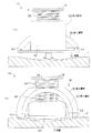
Next, the operation of attracting the
First, a comparative example will be described.
FIG. 20 is a perspective view of a suction cup device of a comparative example, and FIGS. 21A and 21B are cross-sectional explanatory views in the case where the
In the comparative example, the pressing
The lower end of the pressing
In this comparative example, similarly to the present embodiment, an
When the
Therefore, the entire circumference of the outer peripheral portion of the
On the other hand, in this embodiment, as will be described below, the suction cup device is used even when the attracted
次に本実施の形態の吸盤装置10を凸状の円筒面からなる被吸着面2に吸着させる動作について説明する。
図6(A)、(B)は吸盤装置10を凸状の円筒面からなる被吸着面2に吸着させる場合の断面説明図である。
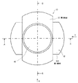
図7(A)、(B)は吸盤装置10を凸状の円筒面からなる被吸着面2に吸着させる場合の外観説明図である。
吸盤装置10を凸状の円筒面からなる被吸着面2に吸着させる際には、図6(B)、図7(A)、(B)に示すように、第1部材30の両端の弾性部40が、被吸着面2を構成する円筒面の周方向に沿った両側の箇所に位置するように(第2部材32の両端の弾性部42が、被吸着面2を構成する円筒面の周方向と直交する方向に沿った両側の箇所に位置するように)、あるいは、図6(A)に示すように、第2部材32の両端の弾性部42が、被吸着面2を構成する円筒面の周方向に沿った両側の箇所に位置するように(第1部材30の両端の弾性部40が、被吸着面2を構成する円筒面の周方向と直交する方向に沿った両側の箇所に位置するように)配置する。
このように第1、第2部材30、32を配置した状態で、アクセサリー取付部16を把持して吸着面22を被吸着面2に臨ませ、吸盤12を被吸着面2に当て付けると、前記と同様に、吸盤12が被吸着面2に吸着され、これにより吸盤装置10が被吸着面2に取り付けられる。
そして、アクセサリー取付部16から手を離すと、第1、第2部材30、32の弾性部40、42が吸盤12の背面24を介して被吸着面2を押圧し、同時に、中心軸14を介して吸盤12の中央部が被吸着面2から離れる方向に強制的に変位される。
この場合、第1、第2部材30、32の弾性部40、42は、互いに異なった高さの箇所に当接できることから、吸盤12の吸着面22の外周部を被吸着面2の湾曲形状に追従して押圧することができる。
また、付勢機構20が、第1、第2コイルスプリング34、36を含んで構成され、それら第1、第2コイルスプリング34、36により複数の部材(第1、第2部材30、32)を個別に付勢しているので、吸盤12の外周部を被吸着面2の湾曲形状に追従させて押圧する上で有利となっている。
これにより、吸盤12の密着度が高められ、アクセサリー取付部16のがたつきが防止された状態でアクセサリー取付部16が被吸着面2に取り付けられる。
すなわち、被吸着面2が凸状の円筒面である場合、この円筒面に対して第1、第2部材30、32を特定の位置関係に配置することで、がたつきが防止された状態でアクセサリー取付部16を被吸着面2に取り付けることが可能となる。
Next, the operation of adsorbing the
6 (A) and 6 (B) are cross-sectional explanatory views in the case where the
FIGS. 7A and 7B are external explanatory views when the
When the
With the first and
Then, when the hand is released from the
In this case, since the
The
Thereby, the adhesion degree of the
That is, when the attracted
次に本実施の形態の吸盤装置10を凹状の円筒面からなる被吸着面2に吸着させる動作について説明する。
図8(A)、(B)は吸盤装置10を凹状の円筒面からなる被吸着面2に吸着させる場合の外観説明図である。
吸盤装置10を凹状の円筒面からなる被吸着面2に吸着させる際には、被吸着面2が凸状の円筒面である場合と同様に、図8(A)に示すように、第1部材30の両端の弾性部40が、被吸着面2を構成する円筒面の周方向に沿った両側の箇所に位置するように(第2部材32の両端の弾性部42が、被吸着面2を構成する円筒面の周方向と直交する方向に沿った両側の箇所に位置するように)、あるいは、図8(B)に示すように、第2部材32の両端の弾性部42が、被吸着面2を構成する円筒面の周方向に沿った両側の箇所に位置するように(第1部材30の両端の弾性部40が、被吸着面2を構成する円筒面の周方向と直交する方向に沿った両側の箇所に位置するように)配置する。
このように第1、第2部材30、32を配置した状態で、アクセサリー取付部16を把持して吸着面22を被吸着面2に臨ませ、吸盤12を被吸着面2に当て付けると、前記と同様に、吸盤12が被吸着面2に吸着され、これにより吸盤装置10が被吸着面2に取り付けられる。そして、アクセサリー取付部16から手を離すと、第1、第2部材30、32の弾性部40、42が吸盤12の背面24を介して被吸着面2を押圧し、同時に、中心軸14を介して吸盤12の中央部が被吸着面2から離れる方向に強制的に変位される。
この場合、第1、第2部材30、32の弾性部40、42は、互いに異なった高さの箇所に当接できることから、吸盤12の吸着面22の外周部を被吸着面2の湾曲形状に追従して押圧することができる。
また、付勢機構20が、第1、第2コイルスプリング34、36を含んで構成され、それら第1、第2コイルスプリング34、36により複数の部材(第1、第2部材30、32)を個別に付勢しているので、吸盤12の外周部を被吸着面2の湾曲形状に追従させて押圧する上で有利となっている。
これにより、アクセサリー取付部16のがたつきが防止された状態でアクセサリー取付部16が被吸着面2に取り付けられる。
したがって、被吸着面2が凹状の円筒面である場合、この円筒面に対して第1、第2部材30、32を特定の位置関係に配置することで、がたつきが防止された状態でアクセサリー取付部16を被吸着面2に取り付けることが可能となる。
Next, the operation of adsorbing the
FIGS. 8A and 8B are external explanatory views when the
When the
With the first and
In this case, since the
The
Thereby, the
Therefore, when the attracted
すなわち、本実施の形態によれば、押圧部材18が、中心軸14に別々に組み付けられ吸盤12の背面24の外周部の周方向に異なった箇所に当接する互いに切り離された第1部材30と第2部材32により構成されているので、被吸着面2が平面である場合のみならず、凸状の円筒面や凹状の円筒面あるいは円筒面以外の湾曲面である場合であっても、吸盤12の外周部を被吸着面2の湾曲形状に追従させて押圧することで、密着度を高めて吸盤装置10を被吸着面2に確実に取り付けることができる。
したがって、吸盤装置10に取り付けられたディスプレイパネルやコントローラーのがたつきを抑制でき、ディスプレイパネルを見やすくすることができ、あるいは、コントローラーの操作性を向上する上で有利となる。
なお、押圧部材18を構成する互いに切り離された部材の数は、上述の第1部材30と第2部材32の2つに限定されず、2つ以上であればよい。
That is, according to the present embodiment, the pressing
Therefore, shakiness of the display panel and the controller attached to the
In addition, the number of the members separated from each other constituting the pressing
(第2の実施の形態)
次に、第2の実施の形態について図面を参照して説明する。
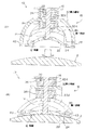
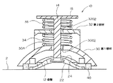
図10は第2の実施の形態の吸盤装置10の斜視図、図11は吸盤装置10の平面図、図12は図10のX矢視図、図13は図10のY矢視図、図14は図10のAA線断面図、図15は図10のBB線断面図である。
第1の実施の形態と同様な箇所、部材に同一の符号を付して説明すると、第2の実施の形態に係る吸盤装置10では、被吸着面2に吸着面22が吸着した際に、押圧部材18が吸盤12の背面24の外周部ではなく、吸着面22が吸着した被吸着面2の箇所の外側の被吸着面2の箇所に当接する点が第1の実施の形態と異なっており、その他の構成は第1の実施の形態と同様であるためその説明を省略する。
すなわち、押圧部材18は、中心軸14に別々に組み付けられ被吸着面2に吸着面22が吸着した際に吸着面22が吸着した被吸着面2の箇所の外側の被吸着面2の箇所で吸盤12の外周部の周方向に異なった箇所に当接する複数の部材により構成されている。
(Second Embodiment)
Next, a second embodiment will be described with reference to the drawings.
10 is a perspective view of the
In the
In other words, the pressing
本実施の形態では、第1の実施の形態と同様に、複数の部材は、第1部材30と第2部材32との2つの部材であり、それら第1、第2部材30、32は硬質な合成樹脂から形成され、共に板状を呈している。
第1部材30は、吸盤12の背面24とアクセサリー取付部16との間の中間の箇所で、第1、第2コイルスプリング34、36の外径よりも大きい幅で吸盤12の直径方向に沿って延在しその延在方向の中央部に中心軸14が移動可能に挿通されその延在方向の両端が、被吸着面2に吸着面22が吸着した際に吸着面22が吸着した被吸着面2の箇所の外側の被吸着面2の箇所に当接可能に形成されている。
より詳細には、第1部材30は、延在方向の中央部が延在方向の両端よりも吸盤12から離れる方向に変位した湾曲した板状を呈している。
そして、第1部材30の延在方向の中央部に孔3002が形成され、中心軸14はこの孔3002に軸方向に移動可能に挿通されている。
In the present embodiment, as in the first embodiment, the plurality of members are two members, the
The
In more detail, the
And the
第2部材32は、第1部材30とアクセサリー取付部16との間の箇所で、第1、第2コイルスプリング34、36の外径よりも大きい幅で第1部材30の延在方向と直交する方向でかつ吸盤12の直径方向に沿って延在しその延在方向の中央部に中心軸14が移動可能に挿通されその延在方向の両端が、被吸着面2に吸着面22が吸着した際に吸着面22が吸着した被吸着面2の箇所の外側の被吸着面2の箇所に当接可能に形成されている。
より詳細には、第2部材32は、延在方向の中央部が延在方向の両端よりも吸盤12から離れる方向に変位した湾曲した板状を呈している。
そして、第2部材32の延在方向の中央部に孔3202が形成され、中心軸14はこの孔3202に軸方向に移動可能に挿通されている。
また、第2部材32の延在方向の中央部32Aは、図10、図13、図15に示すように、アクセサリー取付部16の平面1602に平行する平面部3210で形成され、後述する第2コイルスプリング36の端部を安定した状態で係止させ、また、アクセサリー取付部16と第2部材32の延在方向の中央部32Aとの距離を確保し、吸盤装置10を大型化することなく第2コイルスプリング36の伸縮ストロークを大きく確保するようにしている。
The
In more detail, the
A
Further, the
被吸着面2に吸着面22が吸着した際に吸着面22が吸着した被吸着面2の箇所の外側の被吸着面2の箇所に当接する第1、第2部材30、32の部分は、吸盤12の外周部の周方向に沿って円弧状に延在している。
本実施の形態では、第1の実施の形態と同様に、吸着面22が吸着した被吸着面2の箇所の外側の被吸着面2の箇所に当接する第1、第2部材30、32の部分は、弾性材料により形成された弾性部40、42で構成されている。
When the
In the present embodiment, similar to the first embodiment, the first and
付勢機構20は、アクセサリー取付部16と吸盤12と押圧部材18との間に設けられ吸着面22が被吸着面22に吸着した状態で押圧部材18を、吸着面22が吸着した被吸着面2の箇所の外側の被吸着面2の箇所に押圧させる方向に付勢すると共に吸盤12の中央部を被吸着面22から離れる方向に付勢するものである。
付勢機構20は、中心軸14と、第1コイルスプリング34と、第2コイルスプリング36とを含んで構成されている。
第1コイルスプリング34は、中心軸14に巻装されて第1部材30の延在方向の中央部30Aと第2部材32の延在方向の中央部32Aとの間に設けられ第1部材30の延在方向の中央部30Aと第2部材32の延在方向の中央部32Aとを離す方向に付勢している。
第2コイルスプリング36は、中心軸14に巻装されて第2部材32の延在方向の中央部32Aとアクセサリー取付部16との間に設けられ第2部材32の延在方向の中央部32Aとアクセサリー取付部16とを離す方向に付勢している。
さらに本実施の形態でも、第1の実施の形態と同様に、第1部材30と第2部材32の中心軸14回りの回転を阻止する回転阻止機構が設けられている。
The
The urging
The
The
Further, in the present embodiment, as in the first embodiment, a rotation preventing mechanism for preventing the rotation of the
このような第2の実施の形態によっても第1の実施の形態と同様な効果が奏される。すなわち、押圧部材18が、中心軸14に別々に組み付けられ吸着面22が吸着した被吸着面2の箇所の外側の被吸着面2の異なった箇所に当接する互いに切り離された第1部材30と第2部材32により構成されているので、被吸着面2が平面である場合のみならず、凸状の円筒面や凹状の円筒面あるいは円筒面以外の湾曲面である場合であっても、吸盤12の外周部を被吸着面2の湾曲形状に追従させて押圧することで、密着度を高めて吸盤装置10を被吸着面2に確実に取り付けることができ、したがって、吸盤装置10に取り付けられたディスプレイパネルやコントローラーのがたつきを抑制でき、ディスプレイパネルを見やすくすることができ、あるいは、コントローラーの操作性を向上する上で有利となる。
The effect similar to 1st Embodiment is show | played also by such 2nd Embodiment. That is, the pressing
(第3の実施の形態)
次に、第3の実施の形態について図面を参照して説明する。
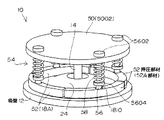
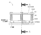
図16は第3の実施の形態の吸盤装置10の斜視図、図17は吸盤装置10の平面図、図18は吸盤装置10の正面図、図19は図18のAA線断面図である。
第1の実施の形態と同様な箇所、部材に同一の符号を付して説明すると、第3の実施の形態に係る吸盤装置10は、アクセサリー取付部50、押圧部材52、付勢機構54などの構成が第1の実施の形態と異なっている。
(Third embodiment)
Next, a third embodiment will be described with reference to the drawings.
16 is a perspective view of the
The same parts and members as those in the first embodiment will be described with the same reference numerals. The
すなわち、第3の実施の形態に係る吸盤装置10は、吸盤12、中心軸14、アクセサリー取付部50、押圧部材52、付勢機構54などを含んで構成されている。
吸盤12の構成および中心軸14の構成は第1の実施の形態と同様である。
That is, the
The configuration of the
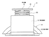
アクセサリー取付部50は、吸盤12の外径に対応した大きさの円板部5002を含んで構成されている。円板部5002の中心に中心軸14の上端が連結されている。
アクセサリー取付部50は、中心軸14と同様に、金属製または硬質な合成樹脂から形成されている。
図19に示すように、円板部5002の外周部に周方向に等間隔をおいて複数の軸挿通孔5004が形成されている。
アクセサリー取付部50には、例えば、カーナビゲーション装置やテレビジョン装置のディスプレイパネルや、また、種々の車載機器をリモートコントロールするためのコントローラーなどが着脱可能に取着される。
The
Similar to the
As shown in FIG. 19, a plurality of
For example, a display panel of a car navigation device or a television device, a controller for remotely controlling various in-vehicle devices, and the like are detachably attached to the
押圧部材52は、吸盤12の背面24の外周部に当接可能に設けられている。
押圧部材52は、互いに切り離され吸盤12の背面24の外周部の周方向に異なった箇所に当接する複数の部材52Aにより構成されている。
本実施の形態では、複数の部材52Aは、硬質な合成樹脂から形成され、共に板状でそれぞれ吸盤12の背面の外周部の周方向に沿って円弧状に延在形成されている。
本実施の形態では、複数の部材52Aは4つ設けられているが、部材52Aの数は2つ以上であればよい。
なお、第3の実施の形態では、第1の実施の形態の弾性部40、42を省略しているが、第1の実施の形態と同様に、複数の部材52Aが吸盤12の背面24の外周部に当接する部分に、弾性材料により形成された弾性部40、42を設けるようにしてもよい。
図19に示すように、複数の部材52Aの上面でかつその延在方向の中央部には、円筒面からなる凹部1810が上方に開放状に形成されている。
The pressing
The pressing
In the present embodiment, the plurality of
In the present embodiment, four
In the third embodiment, the
As shown in FIG. 19, a
付勢機構54は、複数の連結軸56と、複数のコイルスプリング58とを含んで構成され、それら連結軸56とコイルスプリング58は部材52Aに対応した数で設けられている。
各連結軸56は、中心軸14と平行して延在しその下端が部材52Aの凹部1810に傾動可能に結合され、その上端がアクセサリー取付部の軸挿通孔5004に軸方向に移動可能に挿通されて配設されている。
各連結軸56がアクセサリー取付部50の上面に突出する端部に、軸挿通孔5004の内径よりも大きい寸法の直径で円盤状に形成されたストッパ5602が設けられている。
このストッパは、連結軸56の吸盤12方向への移動限界位置を規制するものである。
The urging
Each connecting
A
This stopper regulates the movement limit position of the connecting
コイルスプリング58は、各連結軸56に巻装され複数の部材をそれぞれアクセサリー取付部50から離れる方向に付勢している。
本実施の形態では、連結軸56の下端寄りの箇所につば部5604が形成され、コイルスプリング58は、その長手方向の一端がアクセサリー取付部50に係止し、その長手方向の他端がつば部5604に係止して配設されている。
すなわち、第3の実施の形態では、押圧部材52を構成する複数の部材52Aは、吸盤12とアクセサリー取付部50との間で中心軸14の軸方向に移動可能に(より詳細には、中心軸14の軸方向と平行する方向に移動可能に)、アクセサリー取付部50および連結軸56ならびにコイルスプリング58を介してそれぞれ中心軸14に別々に組み付けられていることになる。
The
In the present embodiment, a
That is, in the third embodiment, the plurality of
このような第3の実施の形態によっても、第1の実施の形態と同様に、押圧部材52が、中心軸14に別々に組み付けられ吸盤12の背面24の外周部の周方向に異なった箇所に当接する互いに切り離された4つの部材52Aにより構成されているので、被吸着面2が平面である場合のみならず、凸状の円筒面や凹状の円筒面あるいは円筒面以外の湾曲面である場合であっても、吸盤12の外周部を被吸着面2の湾曲形状に追従させて押圧できる。
また、各部材52Aをそれぞれコイルスプリング58により個別に付勢しているので、吸盤12の外周部を被吸着面2の湾曲形状に追従させて押圧する上で有利となっている。
したがって、第3の実施の形態によっても、吸盤12の密着度を高めて吸盤装置10を被吸着面2に確実に取り付けることができ、吸盤装置10に取り付けられたディスプレイパネルやコントローラーのがたつきを抑制し、ディスプレイパネルを見やすくすることができ、あるいは、コントローラーの操作性を向上する上で有利となる。
Also in the third embodiment, similarly to the first embodiment, the pressing
Further, since each
Therefore, also according to the third embodiment, the degree of adhesion of the
なお、第1の実施の形態と第2の実施の形態との関係のように、第3の実施の形態においても、押圧部材52(複数の部材52A)を吸盤12の背面24の外周部ではなく、吸着面22が吸着した被吸着面2の箇所の外側の被吸着面2の箇所に当接するようにしてもよく、このように構成しても第3の実施の形態と同様な効果が奏される。
また、第1、第2、第3の実施の形態では、ディスプレイパネルや種々の車載機器のコントローラーなどを取り付けるための吸盤装置10について説明したが、吸盤装置10により支持する物品は車載用の物品に限定されるものではなく、様々な物品に適用可能である。
As in the relationship between the first embodiment and the second embodiment, also in the third embodiment, the pressing member 52 (the plurality of
In the first, second, and third embodiments, the
10……吸盤装置、12……吸盤、14……中心軸、16……アクセサリー取付部、18……押圧部材、20……付勢機構、22……吸着面、24……背面、30……第1部材、32……第2部材。
DESCRIPTION OF
Claims (16)
前記吸盤の背面の中央部から前記厚さ方向に沿って前記背面から離れる方向に突設された中心軸と、
前記中心軸の先端に連結されたアクセサリー取付部と、
前記吸盤と前記アクセサリー取付部との間で前記中心軸に組み付けられ前記吸盤の背面の外周部に当接可能な押圧部材と、
前記アクセサリー取付部と前記押圧部材との間に設けられ前記吸着面が前記被吸着面に吸着した状態で前記押圧部材を前記背面の外周部に押圧させる方向に付勢すると共に前記吸盤の中央部を前記被吸着面から離れる方向に付勢する付勢機構と、
を備えた吸盤装置であって、
前記押圧部材は、
前記吸盤の背面と前記アクセサリー取付部との間で前記吸盤の直径方向に沿って延在しその延在方向の中央部に前記中心軸が移動可能に挿通されその延在方向の両端が前記背面の外周部にそれぞれ当接する第1部材と、
前記第1部材と前記アクセサリー取付部との間で前記第1部材の延在方向と交差する方向でかつ前記吸盤の直径方向に沿って延在しその延在方向の中央部に前記中心軸が移動可能に挿通されその延在方向の両端が前記背面の外周部にそれぞれ当接する第2部材とを含んで構成されており、
前記付勢機構は、
前記中心軸と、
前記中心軸に巻装されて前記第1部材の延在方向の中央部と前記第2部材の延在方向の中央部との間に設けられ前記第1部材の延在方向の中央部と前記第2部材の延在方向の中央部とを離す方向に付勢する第1コイルスプリングと、
前記中心軸に巻装されて前記第2部材の延在方向の中央部と前記アクセサリー取付部との間に設けられ前記第2部材の延在方向の中央部と前記アクセサリー取付部とを離す方向に付勢する第2コイルスプリングとを含んで構成されている
吸盤装置。 A suction cup in which one surface in the thickness direction is an adsorption surface and the other surface is a back surface;
A central axis projecting in a direction away from the back surface along the thickness direction from the center of the back surface of the suction cup;
An accessory attachment connected to the tip of the central axis;
A pressing member assembled to the central shaft between the suction cup and the accessory mounting portion and capable of contacting the outer peripheral portion of the back surface of the suction cup;
The central portion of the suction cup is urged in the direction of pressing the pressing member against the outer peripheral portion of the back surface with the suction surface being adsorbed to the attracted surface provided between the accessory mounting portion and the pressing member. An urging mechanism for urging the direction away from the attracted surface;
A suction cup device comprising:
The pressing member is
The suction cup extends along the diameter direction of the suction cup between the back face of the suction cup and the accessory mounting portion, and the central axis is movably inserted in the central portion of the extension direction, and both ends in the extending direction are the back face. First members that respectively contact the outer peripheral portions of
The central axis extends between the first member and the accessory mounting portion in a direction intersecting with the extending direction of the first member and along the diameter direction of the suction cup, and the central axis at the central portion in the extending direction. A second member that is movably inserted and has both ends extending in contact with the outer peripheral portion of the back surface.
The biasing mechanism is
The central axis;
Wrapped around the central shaft and provided between the central part in the extending direction of the first member and the central part in the extending direction of the second member, and the central part in the extending direction of the first member and the A first coil spring that urges the second member in a direction away from the central portion in the extending direction;
A direction wound around the central shaft and provided between a central portion in the extending direction of the second member and the accessory mounting portion, and separating the central portion in the extending direction of the second member from the accessory mounting portion. A suction cup device including a second coil spring that biases the coil spring .
前記吸盤の背面の中央部から前記厚さ方向に沿って前記背面から離れる方向に突設された中心軸と、
前記中心軸の先端に連結されたアクセサリー取付部と、
前記吸盤と前記アクセサリー取付部との間で前記中心軸に組み付けられ被吸着面に前記吸着面が吸着した際に前記吸着面が吸着した前記被吸着面箇所の外側の前記被吸着面箇所に当接可能な押圧部材と、
前記アクセサリー取付部と前記押圧部材との間に設けられ前記吸着面が前記被吸着面に吸着した状態で前記押圧部材を前記吸着面が吸着した前記被吸着面箇所の外側の前記被吸着面箇所に押圧させる方向に付勢すると共に前記吸盤の中央部を前記被吸着面から離れる方向に付勢する付勢機構と、
を備えた吸盤装置であって、
前記押圧部材は、
前記吸盤の背面と前記アクセサリー取付部との間で前記吸盤の直径方向に沿って延在しその延在方向の中央部に前記中心軸が移動可能に挿通されその延在方向の両端が、前記吸着面が前記被吸着面に吸着した状態で前記吸着面が吸着した前記被吸着面箇所の外側の前記被吸着面箇所に当接する第1部材と、
前記第1部材と前記アクセサリー取付部との間で前記第1部材の延在方向と交差する方向でかつ前記吸盤の直径方向に沿って延在しその延在方向の中央部に前記中心軸が移動可能に挿通されその延在方向の両端が、前記吸着面が前記被吸着面に吸着した状態で前記吸着面が吸着した前記被吸着面箇所の外側の前記被吸着面箇所に当接する第2部材とを含んで構成されており、
前記付勢機構は、
前記中心軸と、
前記中心軸に巻装されて前記第1部材の延在方向の中央部と前記第2部材の延在方向の中央部との間に設けられ前記第1部材の延在方向の中央部と前記第2部材の延在方向の中央部とを離す方向に付勢する第1コイルスプリングと、
前記中心軸に巻装されて前記第2部材の延在方向の中央部と前記アクセサリー取付部との間に設けられ前記第2部材の延在方向の中央部と前記アクセサリー取付部とを離す方向に付勢する第2コイルスプリングとを含んで構成されている
吸盤装置。 A suction cup in which one surface in the thickness direction is an adsorption surface and the other surface is a back surface;
A central axis projecting in a direction away from the back surface along the thickness direction from the center of the back surface of the suction cup;
An accessory attachment connected to the tip of the central axis;
When the suction surface is attached to the suction surface and is attached to the suction surface between the suction cup and the accessory mounting portion, the suction surface contacts the suction surface portion outside the suction surface portion. A pressing member capable of contacting;
The adsorbed surface portion outside the adsorbed surface portion where the adsorbing surface adsorbs the pressing member with the adsorbing surface adsorbed to the adsorbed surface provided between the accessory mounting portion and the pressing member. An urging mechanism for urging the central portion of the suction cup in a direction away from the attracted surface;
A suction cup device comprising:
The pressing member is
It extends along the diameter direction of the suction cup between the back surface of the suction cup and the accessory mounting portion, and the central axis is movably inserted in the central portion of the extension direction, and both ends in the extending direction are A first member abutting on the attracted surface portion outside the attracted surface portion adsorbed by the attracted surface in a state where the attracted surface is adsorbed on the attracted surface;
The central axis extends between the first member and the accessory mounting portion in a direction intersecting with the extending direction of the first member and along the diameter direction of the suction cup, and the central axis at the central portion in the extending direction. A second end that is movably inserted and has both ends extending in contact with the attracted surface portion outside the attracted surface portion adsorbed by the attracted surface while the attracted surface is attracted to the attracted surface. It is comprised including the member,
The biasing mechanism is
The central axis;
Wrapped around the central shaft and provided between the central part in the extending direction of the first member and the central part in the extending direction of the second member, and the central part in the extending direction of the first member and the A first coil spring that urges the second member in a direction away from the central portion in the extending direction;
A direction wound around the central shaft and provided between a central portion in the extending direction of the second member and the accessory mounting portion, and separating the central portion in the extending direction of the second member from the accessory mounting portion. And a second coil spring that biases
Suction cup device.
請求項2記載の吸盤装置。 The portion of the first member and the second member that abuts the attracted surface portion outside the attracted surface portion where the attracted surface is adsorbed in a state where the attracted surface is adsorbed to the attracted surface, It extends in an arc shape along the circumferential direction of the outer periphery of the suction cup
The suction cup device according to claim 2.
請求項1記載の吸盤装置。 The first member and the second member are formed of a hard material, and an elastic portion formed of an elastic material is provided at a portion where the first member and the second member abut on the outer peripheral portion of the back surface of the suction cup. Has been
The suction cup device according to claim 1.
請求項2記載の吸盤装置。 The first member and the second member are made of a hard material, and the sucked surface of the first member and the second member is attracted to the attracted surface while the attracted surface is attracted to the attracted surface. An elastic portion made of an elastic material is provided at a portion that contacts the attracted surface portion outside the surface portion.
The suction cup device according to claim 2.
請求項1記載の吸盤装置。 Each of the first member and the second member is formed in a curved shape in which a central portion in the extending direction is displaced in a direction away from the suction cups than both ends in the extending direction.
The suction cup device according to claim 1 .
請求項2記載の吸盤装置。 Each of the first member and the second member is formed in a curved shape in which a central portion in the extending direction is displaced in a direction away from the suction cups than both ends in the extending direction.
The suction cup device according to claim 2 .
請求項6または7記載の吸盤装置。 The first member and the second member are both plate-shaped, each having a width larger than the outer diameter of the first and second coil springs, and the central portion in the extending direction is more than the both ends in the extending direction. It is formed to extend in a curved shape displaced in a direction away from the suction cup
The suction cup device according to claim 6 or 7 .
請求項8記載の吸盤装置。 The location of the accessory mounting portion to which the tip of the central axis is connected is a plane orthogonal to the central axis, and the location facing the plane at the central portion in the extending direction of the second member is the A plane part parallel to the plane is formed
The suction cup device according to claim 8 .
請求項1または2記載の吸盤装置。 A rotation prevention mechanism is provided for preventing rotation of the first member and the second member around the central axis.
The suction cup device according to claim 1 or 2 .
前記吸盤本体は、弾性を有する材料から形成され前記背面を構成しており、
前記ゲル層は、ゲルから形成され前記吸盤本体に取着されて前記吸着面を構成している
請求項1または2記載の吸盤装置。 The suction cup is composed of a suction cup body and a gel layer,
The suction cup body is formed of an elastic material and constitutes the back surface.
The gel layer is made of gel and attached to the suction cup body to constitute the suction surface.
The suction cup device according to claim 1 or 2.
前記吸盤の背面の中央部から前記厚さ方向に沿って前記背面から離れる方向に突設された中心軸と、A central axis projecting in a direction away from the back surface along the thickness direction from the center of the back surface of the suction cup;
前記中心軸の先端に連結されたアクセサリー取付部と、An accessory attachment connected to the tip of the central axis;
前記吸盤と前記アクセサリー取付部との間で前記中心軸に組み付けられ前記吸盤の背面の外周部に当接可能な押圧部材と、A pressing member assembled to the central shaft between the suction cup and the accessory mounting portion and capable of contacting the outer peripheral portion of the back surface of the suction cup;
前記アクセサリー取付部と前記押圧部材との間に設けられ前記吸着面が前記被吸着面に吸着した状態で前記押圧部材を前記背面の外周部に押圧させる方向に付勢すると共に前記吸盤の中央部を前記被吸着面から離れる方向に付勢する付勢機構と、The central portion of the suction cup is urged in the direction of pressing the pressing member against the outer peripheral portion of the back surface with the suction surface being adsorbed to the attracted surface provided between the accessory mounting portion and the pressing member. An urging mechanism for urging the direction away from the attracted surface;
を備えた吸盤装置であって、A suction cup device comprising:
前記押圧部材は、前記中心軸の軸方向に移動可能に前記中心軸に別々に組み付けられ前記吸盤の背面の外周部の周方向に異なった箇所に当接する互いに切り離された複数の部材により構成され、前記押圧部材を構成する前記複数の部材は、それぞれ前記吸盤の背面の外周部の周方向に沿って円弧状に延在形成されており、The pressing member is composed of a plurality of members separated from each other, which are separately assembled to the central axis so as to be movable in the axial direction of the central axis and come into contact with different locations in the circumferential direction of the outer peripheral portion of the back surface of the suction cup. The plurality of members constituting the pressing member are each formed to extend in an arc shape along the circumferential direction of the outer peripheral portion of the back surface of the suction cup,
前記付勢機構は、The biasing mechanism is
前記中心軸と平行して延在しその下端が前記複数の部材にそれぞれ連結されその上端が前記アクセサリー取付部にそれぞれ移動可能に支持された複数の連結軸と、A plurality of connecting shafts extending in parallel with the central axis, the lower ends of which are connected to the plurality of members, and the upper ends of the connecting shafts are movably supported by the accessory mounting portions;
前記各連結軸に巻装され前記複数の部材をそれぞれ前記アクセサリー取付部から離れる方向に付勢する複数のコイルスプリングとを含んで構成されているA plurality of coil springs wound around each of the connecting shafts and biasing the plurality of members in directions away from the accessory mounting portions.
吸盤装置。Suction cup device.
前記吸盤の背面の中央部から前記厚さ方向に沿って前記背面から離れる方向に突設された中心軸と、A central axis projecting in a direction away from the back surface along the thickness direction from the center of the back surface of the suction cup;
前記中心軸の先端に連結されたアクセサリー取付部と、An accessory attachment connected to the tip of the central axis;
前記吸盤と前記アクセサリー取付部との間で前記中心軸に組み付けられ被吸着面に前記吸着面が吸着した際に前記吸着面が吸着した前記被吸着面箇所の外側の前記被吸着面箇所に当接可能な押圧部材と、When the suction surface is attached to the suction surface and is attached to the suction surface between the suction cup and the accessory mounting portion, the suction surface contacts the suction surface portion outside the suction surface portion. A pressing member capable of contacting;
前記アクセサリー取付部と前記押圧部材との間に設けられ前記吸着面が前記被吸着面に吸着した状態で前記押圧部材を前記吸着面が吸着した前記被吸着面箇所の外側の前記被吸着面箇所に押圧させる方向に付勢すると共に前記吸盤の中央部を前記被吸着面から離れる方向に付勢する付勢機構と、The adsorbed surface portion outside the adsorbed surface portion where the adsorbing surface adsorbs the pressing member with the adsorbing surface adsorbed to the adsorbed surface provided between the accessory mounting portion and the pressing member. An urging mechanism for urging the central portion of the suction cup in a direction away from the attracted surface;
を備えた吸盤装置であって、A suction cup device comprising:
前記押圧部材は、前記中心軸の軸方向に移動可能に前記中心軸に別々に組み付けられ前記吸着面が吸着した前記被吸着面箇所の外側の前記被吸着面箇所で吸盤の外周部の周方向に異なった箇所に当接する互いに切り離された複数の部材により構成され、前記押圧部材を構成する前記複数の部材は、それぞれ前記吸盤の背面の外周部の周方向に沿って円弧状に延在形成されており、The pressing member is assembled separately to the central axis so as to be movable in the axial direction of the central axis, and the circumferential direction of the outer peripheral portion of the suction cup at the suctioned surface portion outside the suctioned surface portion where the suction surface is attracted Are formed of a plurality of members separated from each other, and each of the plurality of members constituting the pressing member extends in an arc shape along the circumferential direction of the outer peripheral portion of the back surface of the suction cup. Has been
前記付勢機構は、The biasing mechanism is
前記中心軸と平行して延在しその下端が前記複数の部材にそれぞれ連結されその上端が前記アクセサリー取付部にそれぞれ移動可能に支持された複数の連結軸と、A plurality of connecting shafts extending in parallel with the central axis, the lower ends of which are connected to the plurality of members, and the upper ends of the connecting shafts are movably supported by the accessory mounting portions;
前記各連結軸に巻装され前記複数の部材をそれぞれ前記アクセサリー取付部から離れる方向に付勢する複数のコイルスプリングとを含んで構成されているA plurality of coil springs wound around each of the connecting shafts and biasing the plurality of members in directions away from the accessory mounting portions.
吸盤装置。Suction cup device.
請求項12または13記載の吸盤装置。 A stopper for restricting the movement limit position of the connecting shaft in the suction cup direction is provided.
The suction cup device according to claim 12 or 13 .
請求項12または13記載の吸盤装置。 A flange portion is formed near the lower end of the connecting shaft, and the coil spring has one end in the longitudinal direction locked to the accessory mounting portion and the other end in the longitudinal direction locked to the collar portion. Arranged
The suction cup device according to claim 12 or 13 .
前記円板部の中心に前記中心軸の上端が連結され、
前記円板部の外周部に周方向に間隔をおいて複数の軸挿通孔が形成され、
前記複数の連結軸はそれらの上部が前記軸挿通孔に挿通されて配設されている
請求項12または13記載の吸盤装置。 The accessory mounting part is configured to include a disk part having a size corresponding to the outer diameter of the suction cup,
The upper end of the central axis is connected to the center of the disc part,
A plurality of shaft insertion holes are formed at intervals in the circumferential direction on the outer peripheral portion of the disk portion,
The plurality of connecting shafts are arranged such that upper portions thereof are inserted into the shaft insertion holes.
The suction cup device according to claim 12 or 13 .
Priority Applications (1)
| Application Number | Priority Date | Filing Date | Title |
|---|---|---|---|
| JP2006230132A JP4816331B2 (en) | 2006-08-28 | 2006-08-28 | Suction cup device |
Applications Claiming Priority (1)
| Application Number | Priority Date | Filing Date | Title |
|---|---|---|---|
| JP2006230132A JP4816331B2 (en) | 2006-08-28 | 2006-08-28 | Suction cup device |
Publications (3)
| Publication Number | Publication Date |
|---|---|
| JP2008051286A JP2008051286A (en) | 2008-03-06 |
| JP2008051286A5 JP2008051286A5 (en) | 2009-10-22 |
| JP4816331B2 true JP4816331B2 (en) | 2011-11-16 |
Family
ID=39235532
Family Applications (1)
| Application Number | Title | Priority Date | Filing Date |
|---|---|---|---|
| JP2006230132A Expired - Fee Related JP4816331B2 (en) | 2006-08-28 | 2006-08-28 | Suction cup device |
Country Status (1)
| Country | Link |
|---|---|
| JP (1) | JP4816331B2 (en) |
Cited By (3)
| Publication number | Priority date | Publication date | Assignee | Title |
|---|---|---|---|---|
| CN107709632A (en) * | 2015-07-02 | 2018-02-16 | 三菱综合材料株式会社 | Water-dispersion type insulating coating formation electrodeposit liquid |
| CN108281841A (en) * | 2018-01-15 | 2018-07-13 | 熊飞燕 | A kind of terminal plate safe to use |
| CN108281840A (en) * | 2018-01-15 | 2018-07-13 | 熊飞燕 | A kind of improvement insert row safe to use |
Families Citing this family (11)
| Publication number | Priority date | Publication date | Assignee | Title |
|---|---|---|---|---|
| US7793899B2 (en) * | 2008-11-10 | 2010-09-14 | Eagle Fan | Structure for a suction device |
| JP5154376B2 (en) * | 2008-11-18 | 2013-02-27 | 株式会社デザインネットワーク | Adsorption device |
| KR200458737Y1 (en) * | 2009-06-19 | 2012-03-06 | 김국환 | Absorptive apparatus detached by one-touch mode |
| CN102192232B (en) * | 2010-03-04 | 2012-12-19 | 启碁科技股份有限公司 | Suction disc device |
| KR20120129450A (en) * | 2011-05-20 | 2012-11-28 | 송순영 | Adhensive supporter |
| CN102518641A (en) * | 2011-12-26 | 2012-06-27 | 邹德骏 | Multi-purpose powerful hanger |
| CN103089793B (en) * | 2013-01-25 | 2015-10-07 | 中国计量学院 | Based on the bionical self adaption adsorbent equipment of multilevel shape memory alloy spring |
| CN104773223A (en) * | 2015-04-07 | 2015-07-15 | 浙江工业大学 | Wall climbing robot traveling mechanism on basis of negative pressure adsorption feet |
| CN104773222B (en) * | 2015-04-07 | 2017-05-24 | 浙江工业大学 | Negative-pressure adsorption foot suitable for non-horizontal smooth wall surface wall-climbing robot |
| CN107956782A (en) * | 2017-12-21 | 2018-04-24 | 南京熊猫电子股份有限公司 | Acetabula device |
| JP6755290B2 (en) * | 2018-11-30 | 2020-09-16 | 日本ペイントホールディングス株式会社 | Suction device and suction cup |
Family Cites Families (4)
| Publication number | Priority date | Publication date | Assignee | Title |
|---|---|---|---|---|
| JPS497370U (en) * | 1972-04-24 | 1974-01-22 | ||
| JPS49127680U (en) * | 1972-11-01 | 1974-11-01 | ||
| JPH0796814B2 (en) * | 1989-08-28 | 1995-10-18 | 株式会社大林組 | Retractable roof |
| KR200338320Y1 (en) * | 2003-10-11 | 2004-01-13 | 최민우 | vacuum fixer |
-
2006
- 2006-08-28 JP JP2006230132A patent/JP4816331B2/en not_active Expired - Fee Related
Cited By (5)
| Publication number | Priority date | Publication date | Assignee | Title |
|---|---|---|---|---|
| CN107709632A (en) * | 2015-07-02 | 2018-02-16 | 三菱综合材料株式会社 | Water-dispersion type insulating coating formation electrodeposit liquid |
| TWI709613B (en) * | 2015-07-02 | 2020-11-11 | 日商三菱綜合材料股份有限公司 | Water-dispersible electrodeposition solution for forming insulation coating |
| CN107709632B (en) * | 2015-07-02 | 2020-11-27 | 三菱综合材料株式会社 | Electrodeposition liquid for forming water-dispersed insulating coating film |
| CN108281841A (en) * | 2018-01-15 | 2018-07-13 | 熊飞燕 | A kind of terminal plate safe to use |
| CN108281840A (en) * | 2018-01-15 | 2018-07-13 | 熊飞燕 | A kind of improvement insert row safe to use |
Also Published As
| Publication number | Publication date |
|---|---|
| JP2008051286A (en) | 2008-03-06 |
Similar Documents
| Publication | Publication Date | Title |
|---|---|---|
| JP4816331B2 (en) | Suction cup device | |
| JP4802938B2 (en) | Suction cup device | |
| JP4254846B2 (en) | Suction cup device | |
| JP4973262B2 (en) | Suction cup and suction cup device | |
| JP4862559B2 (en) | Sucker | |
| JP4305670B2 (en) | Sucker | |
| JP2008089088A (en) | Connection structure and joint | |
| TWI401383B (en) | Holder and sucker thereof | |
| JP2008093026A (en) | Article attaching utensil | |
| JP2008051296A (en) | Sucker | |
| JP2009216111A (en) | Suction cup device and article attaching apparatus | |
| JP2008064264A (en) | Sucker device | |
| JP4887884B2 (en) | Suction cup device | |
| JP5125687B2 (en) | Suction cup and suction cup device | |
| JP4840430B2 (en) | Suction cup device | |
| JP4985605B2 (en) | Suction cup device | |
| JP2006224199A (en) | Suction apparatus | |
| KR20060110040A (en) | Structure for assembling a back warning sensor of vehicles | |
| JP7043610B2 (en) | Coupling and sealing devices | |
| JP4748599B2 (en) | fishing rod | |
| KR20180085245A (en) | Adsorption tool | |
| JPH11344020A (en) | Suction cup, pressure board for it, and adsorptive tool | |
| JP2011048498A (en) | Cushion device of operation pedal | |
| JP2002165399A (en) | Holding structure of motor |
Legal Events
| Date | Code | Title | Description |
|---|---|---|---|
| A521 | Written amendment |
Free format text: JAPANESE INTERMEDIATE CODE: A523 Effective date: 20090817 |
|
| A621 | Written request for application examination |
Free format text: JAPANESE INTERMEDIATE CODE: A621 Effective date: 20090817 |
|
| RD02 | Notification of acceptance of power of attorney |
Free format text: JAPANESE INTERMEDIATE CODE: A7422 Effective date: 20090825 |
|
| A521 | Written amendment |
Free format text: JAPANESE INTERMEDIATE CODE: A523 Effective date: 20090903 |
|
| RD04 | Notification of resignation of power of attorney |
Free format text: JAPANESE INTERMEDIATE CODE: A7424 Effective date: 20091015 |
|
| A977 | Report on retrieval |
Free format text: JAPANESE INTERMEDIATE CODE: A971007 Effective date: 20110427 |
|
| A131 | Notification of reasons for refusal |
Free format text: JAPANESE INTERMEDIATE CODE: A131 Effective date: 20110510 |
|
| A521 | Written amendment |
Free format text: JAPANESE INTERMEDIATE CODE: A523 Effective date: 20110704 |
|
| TRDD | Decision of grant or rejection written | ||
| A01 | Written decision to grant a patent or to grant a registration (utility model) |
Free format text: JAPANESE INTERMEDIATE CODE: A01 Effective date: 20110802 |
|
| A01 | Written decision to grant a patent or to grant a registration (utility model) |
Free format text: JAPANESE INTERMEDIATE CODE: A01 |
|
| A61 | First payment of annual fees (during grant procedure) |
Free format text: JAPANESE INTERMEDIATE CODE: A61 Effective date: 20110815 |
|
| FPAY | Renewal fee payment (event date is renewal date of database) |
Free format text: PAYMENT UNTIL: 20140909 Year of fee payment: 3 |
|
| FPAY | Renewal fee payment (event date is renewal date of database) |
Free format text: PAYMENT UNTIL: 20140909 Year of fee payment: 3 |
|
| LAPS | Cancellation because of no payment of annual fees |