JP4815552B2 - Method for producing shochu concentrate - Google Patents
Method for producing shochu concentrate Download PDFInfo
- Publication number
- JP4815552B2 JP4815552B2 JP2005033638A JP2005033638A JP4815552B2 JP 4815552 B2 JP4815552 B2 JP 4815552B2 JP 2005033638 A JP2005033638 A JP 2005033638A JP 2005033638 A JP2005033638 A JP 2005033638A JP 4815552 B2 JP4815552 B2 JP 4815552B2
- Authority
- JP
- Japan
- Prior art keywords
- liquid
- solid
- concentration
- separation
- liquid separation
- Prior art date
- Legal status (The legal status is an assumption and is not a legal conclusion. Google has not performed a legal analysis and makes no representation as to the accuracy of the status listed.)
- Expired - Fee Related
Links
Images


Classifications
-
- Y—GENERAL TAGGING OF NEW TECHNOLOGICAL DEVELOPMENTS; GENERAL TAGGING OF CROSS-SECTIONAL TECHNOLOGIES SPANNING OVER SEVERAL SECTIONS OF THE IPC; TECHNICAL SUBJECTS COVERED BY FORMER USPC CROSS-REFERENCE ART COLLECTIONS [XRACs] AND DIGESTS
- Y02—TECHNOLOGIES OR APPLICATIONS FOR MITIGATION OR ADAPTATION AGAINST CLIMATE CHANGE
- Y02P—CLIMATE CHANGE MITIGATION TECHNOLOGIES IN THE PRODUCTION OR PROCESSING OF GOODS
- Y02P60/00—Technologies relating to agriculture, livestock or agroalimentary industries
- Y02P60/80—Food processing, e.g. use of renewable energies or variable speed drives in handling, conveying or stacking
- Y02P60/87—Re-use of by-products of food processing for fodder production
Landscapes
- Fodder In General (AREA)
- Heat Treatment Of Water, Waste Water Or Sewage (AREA)
- Treatment Of Sludge (AREA)
Description
本発明は、焼酎粕濃縮液の製造方法に関し、詳しくは、濃縮液の流動性に優れ、ポンプでの輸送を可能にする焼酎粕濃縮液の製造方法に関する。 The present invention relates to a method for producing a shochu concentrate, and more particularly, to a method for producing a shochu concentrate that is excellent in fluidity of the concentrate and that can be transported by a pump.
1993年に日本を含む多数の国々でロンドン条約(廃棄物その他の投棄による海洋汚染の防止に関する条約)が採択された。焼酎粕は現在同条約の除外品目として認められているが、現実問題としてはこのまま従来の海洋投棄を継続することは困難な情勢であり、全量陸上処理することを目標に焼酎業界での努力がなされてきた。 In 1993, a number of countries, including Japan, adopted the London Convention (the Convention on the Prevention of Marine Pollution from Waste and Other Disposals). Shochu is currently recognized as an exempted item from the Convention, but as a matter of fact, it is difficult to continue the conventional ocean dumping as it is, and efforts in the shochu industry are aimed at the total disposal of land. Has been made.
焼酎粕には、通常、水分と固形分が含まれ、水分は90重量%以上含まれ、固形分には、多量のたんぱく質、でん粉、繊維分等が含まれている。 Shochu usually contains moisture and solids, and moisture is contained in an amount of 90% by weight or more. The solids contain a large amount of protein, starch, fiber, and the like.
かかる焼酎粕の陸上処理として焼却処理も考えられるが、焼却設備や燃料コストが高くなるため、好ましい手法とは言えない。 Although incineration is also conceivable as an onshore treatment of such shochu, it is not a preferable method because incineration facilities and fuel costs increase.
このため近年、焼酎粕の成分に着目して、飼料を製造する方法が特許文献1、2に提案されている。
For this reason, in recent years,
特許文献1に記載の技術は、焼酎粕を液体分と固体分に分離し、該液体分の懸濁物質を100(g/l)以下に調整後、該液体分と該固体分をそれぞれ別々に乾燥させ、その後、該液体分乾燥物および該固体分乾燥物を混合することを特徴とする焼酎粕から得られる飼料の製造方法である。
The technique described in
特許文献2に記載の技術は、焼酎蒸留残渣液を固液分離し、その分離液を濃縮させて水分含有率65%〜80%の濃縮液を抽出し、該濃縮液と乾草や穀類等の混合原料を所定の割合で混合させてウエットタイプ飼料を製造する方法である。
特許文献1、2に記載のように、焼酎粕から飼料を製造する際、一般に前処理として焼酎粕の原液を固液分離し、そのうちの固形分を乾燥設備に送って乾燥処理する一方、分離液を濃縮設備に送って濃縮処理する。濃縮処理された濃縮液は、濃縮液貯蔵タンク等に輸送され、貯蔵される。
As described in
ここで、濃縮処理された濃縮液は固形分濃度が高められる結果、粘性を有しているため、流動性が悪く、固形分濃度が高められる程ポンプでの輸送が困難となってハンドリング性に劣る問題がある。 Here, as a result of the concentration of the concentrated liquid being increased, the concentrated liquid has viscosity, so that the fluidity is poor, and the higher the solid content concentration is, the more difficult it is to transport with a pump. There is an inferior problem.
そこで、本発明の課題は、濃縮処理された濃縮液の流動性に優れ、ポンプでの輸送を可能にする焼酎粕濃縮液の製造方法を提供することにある。 Then, the subject of this invention is providing the manufacturing method of the shochu concentrate which is excellent in the fluidity | liquidity of the concentrate which was concentrated, and enables the transport with a pump.
本発明の他の課題は、以下の記載によって明らかとなる。 The other subject of this invention becomes clear by the following description.
上記課題は、以下の各発明によって解決される。 The above problems are solved by the following inventions.
(請求項1)
焼酎粕を固液分離手段を用いて固液分離して得られた分離液を、蒸留手段により濃縮して濃縮液を製造する方法において、
前記固液分離手段は、スクリュープレス、デカンタ、セラミックフィルターの少なくともいずれか2種を直列的に併用し、
前記蒸留手段は、加熱された分離液を、スプレーノズルから減圧状態にある蒸発缶の胴内に接線方向から導入するように噴霧するスプレー式蒸発缶を用い、
前記分離液中のSS濃度を1,000mg/l以上6,000mg/l以下にすることを特徴とする焼酎粕濃縮液の製造方法。
(Claim 1)
In a method for producing a concentrated liquid by concentrating a separated liquid obtained by solid-liquid separation of shochu using a solid-liquid separation means by a distillation means
The solid-liquid separation means uses at least any two of a screw press, a decanter, and a ceramic filter in series,
The distillation means uses a spray evaporator that sprays the heated separated liquid so as to be introduced from the spray nozzle into the cylinder of the evaporator in a depressurized state from the tangential direction,
A method for producing a shochu concentrate, wherein the SS concentration in the separated liquid is 1,000 mg / l or more and 6,000 mg / l or less.
(請求項2)
前記固液分離手段は、2種を直列的に併用し、スクリュープレスの後にデカンタを併用することを特徴とする請求項1記載の焼酎粕濃縮液の製造方法。
(Claim 2)
The method for producing a shochu concentrate according to
(請求項3)
前記固液分離手段は、3種を直列的に併用し、スクリュープレス、デカンタの後にセラミックフィルターを併用することを特徴とする請求項1記載の焼酎粕濃縮液の製造方法。
(Claim 3)
The method for producing a shochu concentrate according to
(請求項4)
前記濃縮液の固形分濃度は40重量%以上であることを特徴とする請求項1、2又は3記載の焼酎粕濃縮液の製造方法。
(Claim 4)
The method for producing a shochu concentrate according to claim 1, 2 or 3, wherein the concentration of the solid content of the concentrate is 40 wt% or more.
本発明によると、濃縮処理された濃縮液の流動性に優れるようになり、ポンプでの輸送も可能となる焼酎粕濃縮液の製造方法を提供することができる。 ADVANTAGE OF THE INVENTION According to this invention, the manufacturing method of the shochu concentrate which comes to be excellent in the fluidity | liquidity of the concentrate by which the concentration process was carried out, and can also be conveyed with a pump can be provided.
本発明は、焼酎粕を固液分離手段を用いて固液分離した後、蒸留手段により濃縮して濃縮液を製造する方法において、固液分離した後の分離液中のSS濃度を6,000mg/l以下にすることを特徴とする。 The present invention is a method for producing a concentrate by solid-liquid separation of shochu from solid-liquid separation means and then concentrating by distillation means, and the SS concentration in the separation liquid after solid-liquid separation is 6,000 mg. / L or less.
本発明において、SS濃度の測定方法は、昭和46年環境省告示第59号別表に規定する方法に従った。 In the present invention, the SS concentration was measured according to the method specified in the Schedule of Ministry of the Environment, No. 59, 1971.
固液分離した後の分離液中のSS濃度を6,000mg/l以下にすることで、後工程である濃縮設備に溶解性極小粒子のみが含まれた分離液を流入させることができる。これにより、濃縮設備によって得られる濃縮液の粘度を150cp以下とすることができ、流動性に優れた濃縮液とすることができ、通常のポンプ輸送を可能にすることができて濃縮液のハンドリング性に優れるようになる。 By setting the SS concentration in the separated liquid after the solid-liquid separation to 6,000 mg / l or less, the separated liquid containing only soluble microparticles can be flowed into the concentrating facility as a subsequent step. As a result, the viscosity of the concentrate obtained by the concentration equipment can be reduced to 150 cp or less, the concentrate can be excellent in fluidity, can be transported by a normal pump, and handling the concentrate. It becomes excellent in nature.
より好ましいSS濃度は3,000mg/l以下とすることであり、更に好ましくは1,000mg/l以下とすることである。 A more preferable SS concentration is 3,000 mg / l or less, and even more preferably 1,000 mg / l or less.
SS濃度の下限値は固液分離手段の分離能にも依存するが、本発明の目的を達成する上記6,000mg/l以下であれば本発明において特に限定されるものではない。 The lower limit of the SS concentration depends on the separation ability of the solid-liquid separation means, but is not particularly limited in the present invention as long as it is 6,000 mg / l or less, which achieves the object of the present invention.
本発明に係る濃縮液の製造方法の一例を添付の図面に基づいて説明する。 An example of the manufacturing method of the concentrate which concerns on this invention is demonstrated based on attached drawing.
図1は、本発明に係る濃縮液の製造方法を含む焼酎粕の処理の一例を示すフロー図である。 FIG. 1 is a flow chart showing an example of shochu processing including the method for producing a concentrate according to the present invention.
図1に示すように、焼酎粕は例えばタンクローリーにより処理設備に搬入され、原液貯留タンク1に貯留される。原液貯留タンク1には、腐敗防止のために例えばスチームコイルを内蔵しており、タンク内の温度は焼酎粕温度を60〜80℃に保たれる。また原液貯留タンク1には固形分の沈降防止のために攪拌機(図示せず)を設けることが好ましい。
As shown in FIG. 1, shochu is carried into a processing facility by a tank lorry, for example, and stored in a stock
原液貯留タンク1に搬入される焼酎粕(以下、原液ともいう)は固形分濃度が約6〜10重量%の範囲であり、エタノール濃度が約0.3〜0.8重量%の範囲である。
The shochu (hereinafter also referred to as stock solution) carried into the stock
原液貯留タンク1に貯留された原液は、図示しないポンプにより固液分離設備2に送られ、固液分離される。
The stock solution stored in the stock
本発明において固液分離設備2に用いられる具体的な固液分離手段は、固液分離した後の分離液中のSS濃度を6,000mg/l以下にすることができるものであれば何ら制限なく用いることができるが、中でも、スクリュープレス、デカンタ、セラミックフィルターを好ましく用いることができる。
The specific solid-liquid separation means used for the solid-
固液分離設備2に用いられる固液分離手段は、いずれか1種を単独で用いてもよいし、2種以上を直列的に併用してもよい。特に2種以上の固液分離手段をその特性に応じて使い分け、原液又は分離液中のSS濃度を徐々に小さくなるように固液分離することにより、より効率良く分離液中のSS濃度を6,000mg/l以下とすることができる。
Any one of the solid-liquid separation means used in the solid-
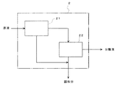
図2は、固液分離設備2の一例として、2種の固液分離手段21、22を併用した態様を示している。
FIG. 2 shows an embodiment in which two types of solid-liquid separation means 21 and 22 are used in combination as an example of the solid-
ここで、固液分離手段21がスクリュープレスであり、固液分離手段22がデカンタである場合について説明すると、原液貯留タンク1内の原液は、まずスクリュープレス21に供給される。スクリュープレス21は、出口に向けて谷径が次第に太くなるスクリューの外周に、小孔やスリット等が形成されたスクリーンが設けられ、原液をスクリューによって出口に向けて移送する過程で、スクリーンから分離液を取り出し、その分離液をデカンタ22に供給する。このスクリュープレス21では、原液中の固形分のうち、繊維等の比較的大きな固形分について分離される。
Here, the case where the solid-liquid separation means 21 is a screw press and the solid-liquid separation means 22 is a decanter will be described. The stock solution in the stock
スクリュープレス21において分離された分離液は、デカンタ22に供給される。デカンタ22では、スクリュープレス21から供給された分離液を遠心力によって更に脱水することで、スクリュープレス21では分離できなかった微小な固形分を遠心分離する。
The separated liquid separated in the
スクリュープレス21及びデカンタ22を経て分離された分離液は濃縮設備3に送られ、スクリュープレス21及びデカンタ22のそれぞれで分離された固形分は乾燥設備7に送られる。
The separated liquid separated through the
また、図2において、固液分離手段21としてデカンタを用い、固液分離手段22としてセラミックフィルターを用いる態様とすることもできる。この場合、原液貯留タンク1内の原液は、まずデカンタ21に供給され、固形分と分離液とに遠心分離され、そのうちの分離液がセラミックフィルター22に供給される。セラミックフィルター22は、例えば、セラミック繊維を織布状、フェルト状に加工したフィルターや、多孔質焼結体としたフィルター等からなり、デカンタ21で分離された分離液から更に固形分をろ過する。
In FIG. 2, a decanter may be used as the solid-
デカンタ21及びセラミックフィルター22を経て分離された分離液は濃縮設備3に送られ、デカンタ21及びセラミックフィルター22のそれぞれで分離された固形分は乾燥設備7に送られる
The separated liquid separated through the
図3は、固液分離設備2の他の例として、3種の固液分離手段21、22、23を併用した態様を示している。
FIG. 3 shows an embodiment in which three types of solid-liquid separation means 21, 22, and 23 are used in combination as another example of the solid-
ここで、固液分離手段21がスクリュープレスであり、固液分離手段22がデカンタであり、固液分離手段23がセラミックフィルターである場合、原液貯留タンク1内の原液は、スクリュープレス21、デカンタ22及びセラミックフィルター23の順に固液分離され、分離液は濃縮設備3に送られ、スクリュープレス21、デカンタ22及びセラミックフィルター23のそれぞれで分離された固形分は乾燥設備7に送られる。
Here, when the solid-liquid separation means 21 is a screw press, the solid-liquid separation means 22 is a decanter, and the solid-liquid separation means 23 is a ceramic filter, the stock solution in the stock
このような固液分離設備2では、最終的に固形分と分離される分離液中のSS濃度を6,000mg/l以下、好ましくは3,000mg/l以下、より好ましくは1,000mg/l以下となるように、固液分離手段における固形分の分離能力を調整する。例えば、スクリュープレスの場合はスクリュー外周のスクリーンの目(孔径)、デカンタの場合は遠心分離の際の駆動条件、セラミックフィルターの場合はフィルターの目(孔径)を規定することにより、分離液中のSS濃度を6,000mg/l以下、好ましくは3,000mg/l以下、より好ましくは1,000mg/l以下となるようにする。
In such a solid-
なお、固液分離設備2は目詰まり防止を実施するために定期的に洗浄することが好ましく、また運転状況に応じて一定期間運転後、苛性ソーダを使用した洗浄を行う。この薬液洗浄は自動洗浄システムとなるように構成されることが好ましい。例えば目詰まり状況を分離液の減少量を検出して、その検出信号をトリガーとして苛性ソーダの供給設備を稼動させて一定時間洗浄運転した後、運転を停止するようなシーケンスプログラムを組むことにより、自動運転が可能となる。
The solid-
濃縮設備3には、固液分離設備2で分離され、SS濃度を6,000mg/l以下とされた分離液が供給される。濃縮設備3に送られた分離液は蒸気で加熱し、分離液中の水分を蒸発させることで濃縮する。この濃縮設備3においては、固液分離設備2から供給されたSS濃度を6,000mg/l以下の分離液を全固形分(TS)濃度約40重量%以上に濃縮することが好ましい。
The concentrating facility 3 is supplied with a separated liquid separated by the solid-
濃縮設備3としては、特に限定されないが、蒸発缶等を用いることができ、例えば3重効用缶(3重効用システム)を採用することは分離効率を向上させる上で好ましい。蒸発缶としてはスプレー式のものを好ましく用いることができる。 Although it does not specifically limit as the concentration equipment 3, An evaporating can etc. can be used, for example, employ | adopting a triple effect can (triple effect system) is preferable when improving separation efficiency. As the evaporator, a spray type can be preferably used.
以下に、本発明において好ましい濃縮設備3の一例について説明する。 Below, an example of the concentration equipment 3 preferable in this invention is demonstrated.
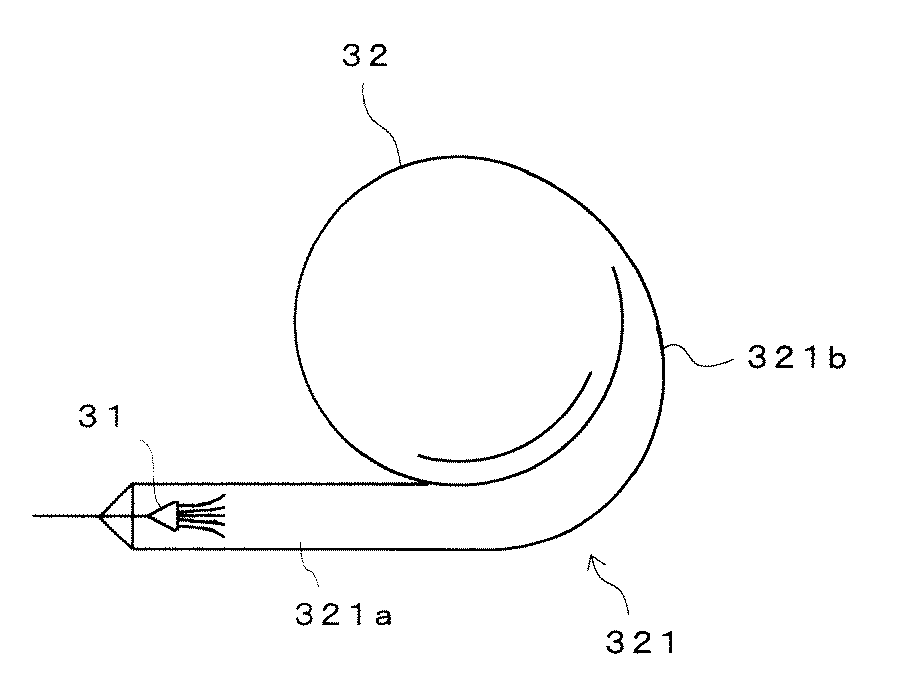
図4は、スプレー式蒸発缶を用いた濃縮設備3の一例を示す全体構成図、図5は、スプレー式蒸発缶のサイクロン部を示す要部断面図である。 FIG. 4 is an overall configuration diagram showing an example of the concentration facility 3 using a spray evaporator, and FIG. 5 is a cross-sectional view of a main part showing a cyclone portion of the spray evaporator.
この濃縮設備3は、内部にスプレーノズル31を備えた蒸発缶32と、この蒸発缶32の底部32aに供給された分離液をスプレーノズル31から吐出するべく加圧するポンプ33と、このポンプ33とスプレーノズル31との間に配設され、管路内の分離液を加熱する加熱器34と、ポンプ33と加熱器34との間に設置された濃度調節計35の測定信号により濃縮液を排出する排出機構36を有している。
The concentration facility 3 includes an
蒸発缶32の内部は、図示しない真空ポンプと連通しており、この真空ポンプによって減圧されている。蒸発缶32には、細径の底部32aに固液分離設備2から供給された分離液が溜められると共に太径胴部の缶径接線方向に、スプレーボックス321が取り付けられている。スプレーボックス321は、図5に示すようにスプレーノズル31を内蔵した直管部321aと、蒸発缶32の接線方向に開口した曲管部321bとから構成されている。従って、直管部321aでスプレーノズル31によって噴霧された分離液は、蒸発した後、曲管部321bから蒸発缶32の胴内に接線方向から導入される。
The inside of the
蒸発缶32の頂部は、後述するドレン処理設備5と連通しており、頂部から蒸発した水分は、ドレン処理設備5において凝縮される。
The top of the
加熱器34は、加熱源としての蒸気が供給されると共に、ポンプ33によって蒸発缶32の底部32a内の分離液が供給され、内部で熱交換が行われることにより、分離液を加熱する。例えば、加熱器34に供給する蒸気温度を80℃とすることにより、55℃の分離液を70℃まで加熱する。蒸気が分離液を加熱して凝縮した後の凝縮水は、加熱器34より外部に排出される。
The
排出機構36は、ポンプ33と加熱器34との間に配設されており、濃度調節計35による検知結果が所定の濃度に達すると、コントロール弁361を開き、排出ポンプ362によって濃縮液を排出する。
The
かかる濃縮設備3では、真空ポンプによって所定の真空度まで減圧された蒸発缶32の底部32aに貯留された分離液を、ポンプ33、加熱器34、スプレーノズル31、スプレーボックス321の順に強制循環すると共に、加熱器34に蒸気を供給する。
In the concentration facility 3, the separated liquid stored in the bottom 32 a of the
ポンプ33によって循環される分離液は、加熱器34において加熱された後、スプレーノズル31から減圧状態にある蒸発缶32の胴内に接線方向から導入されて噴霧される。噴霧された分離液は、サイクロン効果によって気液分離が促進され、蒸気が蒸発缶32の頂部から排出されると共に、濃縮された液体が蒸発缶32の底部32aに貯留され、所定の濃度になるまで、以上の動作が繰り返される。
The separated liquid circulated by the
蒸発缶32内の液濃度が所定の濃度に達すると、濃度調節計35が信号を発し、コントロール弁361が開となり、濃縮液が外部に排出される。
When the liquid concentration in the
濃縮設備3には、分離液の分離効率を向上させる上で、蒸発缶32を用いた例えば3重効用缶(3重効用システム)を採用することが好ましい。
In order to improve the separation efficiency of the separation liquid, for example, a triple effect can (triple effect system) using the
濃縮設備3内の蒸発缶32内にスケーリングなどが発生すると濃縮効率が低下するので、毎日温水で洗浄を行うことが好ましい。この洗浄運転は濃縮工程の一部として予めプログラミングされており、完全自動運転で行われることが好ましい。洗浄排液は原液貯留タンク1に返送され、また運転状況に応じて一定期間運転後、苛性ソーダを使用した洗浄を行う。
If scaling or the like occurs in the
濃縮設備3によって濃縮された濃縮液は、濃縮液貯蔵タンク4に貯蔵された後、タンクローリーなどにより外部に搬出され、具体的には液体の飼料原料として飼料製造会社に販売される。
The concentrated liquid concentrated by the concentration equipment 3 is stored in the concentrated
ここで、濃縮設備3に供給された分離液は固液分離設備2によってSS濃度を6,000mg/l以下に予め前処理されているため、この分離液を濃縮することにより得られた濃縮液は、非常に流動性に優れており、濃縮設備3から濃縮液貯蔵タンク4等への輸送の際、通常のポンプによる輸送が可能となり、極めてハンドリング性に優れた濃縮液となる。特に、濃縮整備3においてTS濃度約40重量%以上の極めて高濃度の濃縮液を製造する場合でも、得られる濃縮液は150cp以下の粘度となって極めて流動性に優れるようになり、本発明において顕著な効果を発揮する。
Here, since the separation liquid supplied to the concentration equipment 3 is pretreated by the solid-
濃縮設備3で発生する蒸発蒸気は、ドレン処理設備5により凝縮され、濃縮ドレンとなる。ドレン処理設備5はコンデンサであり、ドレン処理塔を備えている。蒸発蒸気を冷却するための冷媒は例えば冷却水が用いられ、蒸気と冷却水の間で熱交換され、蒸気を凝縮させる。冷却水との熱的な接触は、ドレン処理塔に至る過程で行われることが凝縮を効率的に行う上で好ましい。 The evaporated vapor generated in the concentration facility 3 is condensed by the drain treatment facility 5 to become concentrated drain. The drain treatment facility 5 is a condenser and includes a drain treatment tower. For example, cooling water is used as the refrigerant for cooling the evaporated steam, and heat is exchanged between the steam and the cooling water to condense the steam. The thermal contact with the cooling water is preferably performed in the process leading to the drain treatment tower in order to efficiently perform the condensation.
得られた濃縮ドレンは、BOD濃度が高いので、ドレン処理塔でBODの主要因であるアルコール(エタノール)を蒸留、回収する。 Since the obtained concentrated drain has a high BOD concentration, alcohol (ethanol), which is a main factor of BOD, is distilled and collected in a drain treatment tower.
ドレン処理塔の塔頂からは約70重量%のエタノール溶液が回収され、ボイラ設備の燃料として使用でき、燃料使用量を低減することができる。 About 70% by weight ethanol solution is recovered from the top of the drain treatment tower and can be used as fuel for boiler equipment, so that the amount of fuel used can be reduced.
ドレン処理塔の塔底からは、エタノール濃度約150〜300mg/lの排液が発生し、この排液は排水処理設備6に送られ、処理される。 From the bottom of the drain treatment tower, waste liquid with an ethanol concentration of about 150 to 300 mg / l is generated, and this waste liquid is sent to the waste water treatment facility 6 for processing.
ドレン処理設備5からの缶出液、脱臭排水及び各洗浄排水等を河川放流可能な水質へ微生物処理する。膜分離活性汚泥方式の採用により省スペースの実現、良好な処理水を得ることができる。 The effluent from the drain treatment facility 5, deodorized effluent, each washing effluent, and the like are microbially treated into water quality that can be discharged into the river. By adopting the membrane separation activated sludge method, space saving and good treated water can be obtained.
設備近くに公共下水道がある場合には、ドレン処理設備のみで直接放流可能な水質にすることが可能であり、排水処理設備を省略することができる。 When there is a public sewer near the facility, it is possible to make the water quality that can be discharged directly with only the drain treatment facility, and the wastewater treatment facility can be omitted.
なお、他の好ましい態様として、上記の濃縮液を更に乾燥して、乾燥品として飼料販売会社に販売することも可能である。かかる乾燥品を製造するには、濃縮液を乾燥設備7に送って乾燥する。
As another preferred embodiment, the concentrated liquid can be further dried and sold to a feed sales company as a dried product. In order to manufacture such a dried product, the concentrated solution is sent to the
乾燥設備7は、特に限定されるわけではないが、例えば旋回式気流乾燥装置を用いることが好ましい。
The
乾燥設備7には、固液分離設備2からの脱水ケーキ及び濃縮設備3からの濃縮液が供給され、これらを混合し、その混合物を高温空気の流れの中に分散投入して、効率良く、水分濃度12重量%以下まで乾燥する。
The
空気加熱源は、蒸気を使用することが好ましい。 The air heating source preferably uses steam.
乾燥品は乾燥品ストックタンク(図示せず)に貯留され場外搬出され、例えば乾燥品として飼料販売会社に販売される。 The dried product is stored in a dried product stock tank (not shown) and carried out of the field, and sold, for example, as a dried product to a feed sales company.
乾燥設備7で発生する排気は臭気成分を含む場合には必要に設けられる脱臭設備(図示せず)へ送られ脱臭される。
When the exhaust gas generated in the
乾燥設備からの排気は、アセトアルデヒドを多く含むため、脱臭スクラバーにて臭気除去後大気へ放出される。 Since the exhaust from the drying facility contains a large amount of acetaldehyde, it is discharged to the atmosphere after odor removal by a deodorizing scrubber.
前述の排水処理設備6では、ドレン処理設備5からの缶出液、脱臭排水及び各洗浄排水等を混合して、河川放流可能な水質となるように微生物処理する。また膜分離活性汚泥方式の採用により、省スペースの実現、良好な処理水を得ることができる。 In the above-described wastewater treatment facility 6, the bottoms from the drainage treatment facility 5, the deodorized wastewater, each washing wastewater, and the like are mixed and subjected to microbial treatment so that the water quality can be discharged into the river. In addition, by adopting the membrane separation activated sludge method, space saving and good treated water can be obtained.
上記のようにして得られた濃縮液は、繊維原料、蛋白原料、穀類、ミネラル、ビタミン等の栄養源となる成分と配合され、通常の混合手段を用いて家畜等の飼料を製造することできる。 The concentrated liquid obtained as described above is blended with ingredients that serve as nutrient sources such as fiber raw materials, protein raw materials, cereals, minerals, vitamins, etc., and feeds such as livestock can be produced using ordinary mixing means. .
以下、実施例により、本発明の効果を例証する。 Hereinafter, the effects of the present invention will be illustrated by examples.
(実施例1)
九州の大麦焼酎製造会社で発生した焼酎粕を、以下に示す固液分離設備で固液分離することで、分離液中のSS濃度が1,000mg/lとなる分離液を得た。
Example 1
The shochu produced at the barley shochu manufacturing company in Kyushu was subjected to solid-liquid separation using the solid-liquid separation equipment shown below to obtain a separated liquid having an SS concentration of 1,000 mg / l in the separated liquid.
固液分離は、スクリュープレス(スクリーン目0.8mm)とデカンタ(3,000G)とセラミックフィルターとを組み合わせて実施した。 The solid-liquid separation was performed by combining a screw press (screen size 0.8 mm), a decanter (3,000 G), and a ceramic filter.
次いで、得られた分離液を、図4に示す濃縮設備で濃縮することにより、濃縮液中のTS(固形分)濃度が40重量%となる濃縮液を得た。 Next, the obtained separated liquid was concentrated with a concentration facility shown in FIG. 4 to obtain a concentrated liquid having a TS (solid content) concentration of 40% by weight in the concentrated liquid.
上記のようにしてにして得られた濃縮液の粘度を測定した結果を表1に示す。なお、粘度の測定は、B型粘度計による60℃粘度測定法による。 The results of measuring the viscosity of the concentrate obtained as described above are shown in Table 1. The viscosity is measured by a 60 ° C. viscosity measurement method using a B-type viscometer.
(実施例2)
実施例1と同一の焼酎粕を、以下に示す固液分離設備で固液分離することで、分離液中のSS濃度が6,000mg/lとなる分離液を得た。
(Example 2)
The same shochu liquor as in Example 1 was subjected to solid-liquid separation using the solid-liquid separation equipment shown below to obtain a separation liquid in which the SS concentration in the separation liquid was 6,000 mg / l.
固液分離は、スクリュープレス(スクリーン目1.0mm)とデカンタ(3,000G)とを組み合わせて実施した。 The solid-liquid separation was performed by combining a screw press (screen size: 1.0 mm) and a decanter (3,000 G).
次いで、得られた分離液を、実施例1と同様の濃縮設備で濃縮することにより、濃縮液中の固形分濃度が40重量%となる濃縮液を得た。 Subsequently, the obtained separated liquid was concentrated with the same concentration equipment as in Example 1 to obtain a concentrated liquid having a solid content concentration of 40% by weight in the concentrated liquid.
得られた濃縮液の粘度を測定した結果を表1に示す。 Table 1 shows the results of measuring the viscosity of the obtained concentrated liquid.
(比較例1)
実施例1と同一の焼酎粕を、以下に示す固液分離設備で固液分離することで、分離液中のSS濃度が10,000mg/lとなる分離液を得た。
(Comparative Example 1)
The same shochu liquor as in Example 1 was subjected to solid-liquid separation using the solid-liquid separation equipment shown below to obtain a separation liquid having an SS concentration of 10,000 mg / l in the separation liquid.
固液分離は、デカンタ(3,000G)のみ用いた。 For solid-liquid separation, only a decanter (3,000 G) was used.
次いで、得られた分離液を、実施例1と同様の濃縮設備で濃縮することにより、濃縮液中のTS(固形分)濃度が40重量%となる濃縮液を得た。 Subsequently, the obtained separated liquid was concentrated using the same concentration equipment as in Example 1 to obtain a concentrated liquid having a TS (solid content) concentration of 40% by weight in the concentrated liquid.
得られた濃縮液の粘度を測定した結果を表1に示す。 Table 1 shows the results of measuring the viscosity of the obtained concentrated liquid.
(比較例2)
実施例1と同一の焼酎粕を、以下に示す固液分離設備で固液分離することで、分離液中のSS濃度が15,000mg/lとなる分離液を得た。
(Comparative Example 2)
The same shochu liquor as in Example 1 was subjected to solid-liquid separation using the following solid-liquid separation equipment, thereby obtaining a separation liquid having an SS concentration of 15,000 mg / l in the separation liquid.
固液分離は、スクリュープレス(スクリーン目1.0mm)のみ用いた。 For solid-liquid separation, only a screw press (screen size: 1.0 mm) was used.
次いで、得られた分離液を、実施例1と同様の濃縮設備で濃縮することにより、濃縮液中のTS(固形分)濃度が40重量%となる濃縮液を得た。 Subsequently, the obtained separated liquid was concentrated using the same concentration equipment as in Example 1 to obtain a concentrated liquid having a TS (solid content) concentration of 40% by weight in the concentrated liquid.
得られた濃縮液の粘度を測定した結果を表1に示す。 Table 1 shows the results of measuring the viscosity of the obtained concentrated liquid.
1:原液貯留タンク
2:固液分離設備
21、22、23:固液分離手段
3:濃縮設備
4:濃縮液貯蔵タンク
5:ドレン処理設備
6:排水処理設備
7:乾燥設備
1: Stock solution storage tank 2: Solid-
Claims (4)
前記固液分離手段は、スクリュープレス、デカンタ、セラミックフィルターの少なくともいずれか2種を直列的に併用し、
前記蒸留手段は、加熱された分離液を、スプレーノズルから減圧状態にある蒸発缶の胴内に接線方向から導入するように噴霧するスプレー式蒸発缶を用い、
前記分離液中のSS濃度を1,000mg/l以上6,000mg/l以下にすることを特徴とする焼酎粕濃縮液の製造方法。 In a method for producing a concentrated liquid by concentrating a separated liquid obtained by solid-liquid separation of shochu using a solid-liquid separation means by a distillation means
The solid-liquid separation means uses at least any two of a screw press, a decanter, and a ceramic filter in series,
The distillation means uses a spray evaporator that sprays the heated separated liquid so as to be introduced from the spray nozzle into the cylinder of the evaporator in a depressurized state from the tangential direction,
A method for producing a shochu concentrate, wherein the SS concentration in the separated liquid is 1,000 mg / l or more and 6,000 mg / l or less.
Priority Applications (1)
| Application Number | Priority Date | Filing Date | Title |
|---|---|---|---|
| JP2005033638A JP4815552B2 (en) | 2005-02-09 | 2005-02-09 | Method for producing shochu concentrate |
Applications Claiming Priority (1)
| Application Number | Priority Date | Filing Date | Title |
|---|---|---|---|
| JP2005033638A JP4815552B2 (en) | 2005-02-09 | 2005-02-09 | Method for producing shochu concentrate |
Publications (2)
| Publication Number | Publication Date |
|---|---|
| JP2006217850A JP2006217850A (en) | 2006-08-24 |
| JP4815552B2 true JP4815552B2 (en) | 2011-11-16 |
Family
ID=36980566
Family Applications (1)
| Application Number | Title | Priority Date | Filing Date |
|---|---|---|---|
| JP2005033638A Expired - Fee Related JP4815552B2 (en) | 2005-02-09 | 2005-02-09 | Method for producing shochu concentrate |
Country Status (1)
| Country | Link |
|---|---|
| JP (1) | JP4815552B2 (en) |
Families Citing this family (4)
| Publication number | Priority date | Publication date | Assignee | Title |
|---|---|---|---|---|
| JP2006320206A (en) * | 2005-05-17 | 2006-11-30 | Nihon Nosan Kogyo Kk | Stockbreeding feed |
| JP5000313B2 (en) * | 2007-01-19 | 2012-08-15 | 三菱瓦斯化学株式会社 | Processing method of cereal distillers |
| EP1955599A1 (en) * | 2007-02-09 | 2008-08-13 | Braunschweigische Maschinenbauanstalt AG | Method and device for drying by-products |
| CN113355050A (en) * | 2021-07-12 | 2021-09-07 | 武秀英 | Biological aldehyde-free glue, biological composite material and preparation method thereof |
Family Cites Families (4)
| Publication number | Priority date | Publication date | Assignee | Title |
|---|---|---|---|---|
| JPS62176598A (en) * | 1985-10-28 | 1987-08-03 | Hitachi Zosen Corp | Treatment method for shochu distillation waste liquid |
| JP3495429B2 (en) * | 1994-08-24 | 2004-02-09 | 三和酒類株式会社 | Method for producing feed obtained from shochu lees |
| JP3898474B2 (en) * | 2000-08-28 | 2007-03-28 | 独立行政法人科学技術振興機構 | Recycling of animal and vegetable waste |
| JP3710459B2 (en) * | 2003-06-27 | 2005-10-26 | 松迫産業有限会社 | Processing method of shochu distilled spirit and liquid fertilizer obtained from shochu distilled spirit |
-
2005
- 2005-02-09 JP JP2005033638A patent/JP4815552B2/en not_active Expired - Fee Related
Also Published As
| Publication number | Publication date |
|---|---|
| JP2006217850A (en) | 2006-08-24 |
Similar Documents
| Publication | Publication Date | Title |
|---|---|---|
| US3323575A (en) | Apparatus and process for dehydrating waste solids concentrates | |
| JP5971732B2 (en) | Method for treating low-concentration distillation waste liquor and apparatus for producing protein-containing products | |
| US3947327A (en) | Process and apparatus for recovering clean water from aqueous wastes | |
| FI88878C (en) | FOERFARANDE FOER RENING AV FRAON TORKNINGSANLAEGGNINGAR HAERSTAMMANDE AVGAS OCH ANLAEGGNING FOER UTFOERANDE AV DETTA FOERFARANDE | |
| CN104178406A (en) | High-efficiency energy-saving white wine continuous distillation method and device | |
| CN106219826B (en) | A system and method for grading and reusing white water of reconstituted tobacco leaves by papermaking method | |
| KR890002346B1 (en) | Method of treatment for separation of oil from oil - containing slurry waste | |
| KR101442796B1 (en) | Method for recycling the food residue | |
| US7060313B2 (en) | Citrus peel processing system and method | |
| JP4815552B2 (en) | Method for producing shochu concentrate | |
| CN104291548A (en) | Treating method for biochemical sludge and treating device for biochemical sludge | |
| CN109173303A (en) | A kind of dry arable land change device of high salt organic waste water thermo-compression evaporation coupling heat pump and its application method | |
| JP2007267702A (en) | Method for producing shochu concentrate | |
| JP4815551B2 (en) | Method for producing shochu concentrate | |
| JP4280101B2 (en) | Vacuum sludge drying method and equipment | |
| USRE26352E (en) | Apparatus and process for uhiynrating waste solids concentrates | |
| CN107021603A (en) | A kind of sludge heat drying system of low energy consumption | |
| JP3646131B2 (en) | Treatment method of organic sludge | |
| CN114349629B (en) | A system and process for recovering sodium acetate from oil by-products | |
| CN218478566U (en) | High concentration sewage concentration system | |
| JP4198832B2 (en) | Vacuum dehydration method and cooker used for vacuum dehydration | |
| WO2015190907A1 (en) | Method for extracting crude palm oil using green technology | |
| JP3646183B2 (en) | Treatment method of organic sludge | |
| CN208964575U (en) | A kind of dry arable land change device of high salt organic waste water thermo-compression evaporation coupling heat pump | |
| CN102585206B (en) | Polyether ketone refining process |
Legal Events
| Date | Code | Title | Description |
|---|---|---|---|
| A621 | Written request for application examination |
Free format text: JAPANESE INTERMEDIATE CODE: A621 Effective date: 20071001 |
|
| A131 | Notification of reasons for refusal |
Free format text: JAPANESE INTERMEDIATE CODE: A131 Effective date: 20101012 |
|
| A521 | Request for written amendment filed |
Free format text: JAPANESE INTERMEDIATE CODE: A523 Effective date: 20101213 |
|
| TRDD | Decision of grant or rejection written | ||
| A01 | Written decision to grant a patent or to grant a registration (utility model) |
Free format text: JAPANESE INTERMEDIATE CODE: A01 Effective date: 20110621 |
|
| A01 | Written decision to grant a patent or to grant a registration (utility model) |
Free format text: JAPANESE INTERMEDIATE CODE: A01 |
|
| A61 | First payment of annual fees (during grant procedure) |
Free format text: JAPANESE INTERMEDIATE CODE: A61 Effective date: 20110629 |
|
| A711 | Notification of change in applicant |
Free format text: JAPANESE INTERMEDIATE CODE: A711 Effective date: 20110729 |
|
| FPAY | Renewal fee payment (event date is renewal date of database) |
Free format text: PAYMENT UNTIL: 20140909 Year of fee payment: 3 |
|
| R150 | Certificate of patent or registration of utility model |
Ref document number: 4815552 Country of ref document: JP Free format text: JAPANESE INTERMEDIATE CODE: R150 |
|
| S531 | Written request for registration of change of domicile |
Free format text: JAPANESE INTERMEDIATE CODE: R313531 |
|
| FPAY | Renewal fee payment (event date is renewal date of database) |
Free format text: PAYMENT UNTIL: 20140909 Year of fee payment: 3 |
|
| R350 | Written notification of registration of transfer |
Free format text: JAPANESE INTERMEDIATE CODE: R350 |
|
| R250 | Receipt of annual fees |
Free format text: JAPANESE INTERMEDIATE CODE: R250 |
|
| S531 | Written request for registration of change of domicile |
Free format text: JAPANESE INTERMEDIATE CODE: R313531 |
|
| R350 | Written notification of registration of transfer |
Free format text: JAPANESE INTERMEDIATE CODE: R350 |
|
| R250 | Receipt of annual fees |
Free format text: JAPANESE INTERMEDIATE CODE: R250 |
|
| R250 | Receipt of annual fees |
Free format text: JAPANESE INTERMEDIATE CODE: R250 |
|
| R250 | Receipt of annual fees |
Free format text: JAPANESE INTERMEDIATE CODE: R250 |
|
| S533 | Written request for registration of change of name |
Free format text: JAPANESE INTERMEDIATE CODE: R313533 |
|
| R350 | Written notification of registration of transfer |
Free format text: JAPANESE INTERMEDIATE CODE: R350 |
|
| R250 | Receipt of annual fees |
Free format text: JAPANESE INTERMEDIATE CODE: R250 |
|
| S531 | Written request for registration of change of domicile |
Free format text: JAPANESE INTERMEDIATE CODE: R313531 |
|
| R350 | Written notification of registration of transfer |
Free format text: JAPANESE INTERMEDIATE CODE: R350 |
|
| R250 | Receipt of annual fees |
Free format text: JAPANESE INTERMEDIATE CODE: R250 |
|
| S533 | Written request for registration of change of name |
Free format text: JAPANESE INTERMEDIATE CODE: R313533 |
|
| R350 | Written notification of registration of transfer |
Free format text: JAPANESE INTERMEDIATE CODE: R350 |
|
| R250 | Receipt of annual fees |
Free format text: JAPANESE INTERMEDIATE CODE: R250 |
|
| S111 | Request for change of ownership or part of ownership |
Free format text: JAPANESE INTERMEDIATE CODE: R313111 |
|
| R350 | Written notification of registration of transfer |
Free format text: JAPANESE INTERMEDIATE CODE: R350 |
|
| LAPS | Cancellation because of no payment of annual fees |