JP4814005B2 - Weighing device - Google Patents
Weighing device Download PDFInfo
- Publication number
- JP4814005B2 JP4814005B2 JP2006215566A JP2006215566A JP4814005B2 JP 4814005 B2 JP4814005 B2 JP 4814005B2 JP 2006215566 A JP2006215566 A JP 2006215566A JP 2006215566 A JP2006215566 A JP 2006215566A JP 4814005 B2 JP4814005 B2 JP 4814005B2
- Authority
- JP
- Japan
- Prior art keywords
- weight
- error
- load
- weighing
- weighed
- Prior art date
- Legal status (The legal status is an assumption and is not a legal conclusion. Google has not performed a legal analysis and makes no representation as to the accuracy of the status listed.)
- Active
Links
- 238000005303 weighing Methods 0.000 title claims description 133
- 238000001514 detection method Methods 0.000 claims description 39
- 238000012937 correction Methods 0.000 claims description 25
- 238000009795 derivation Methods 0.000 claims description 3
- 238000005259 measurement Methods 0.000 description 98
- 238000004364 calculation method Methods 0.000 description 26
- 230000014509 gene expression Effects 0.000 description 20
- 230000005484 gravity Effects 0.000 description 17
- 238000000034 method Methods 0.000 description 15
- 238000005452 bending Methods 0.000 description 5
- 238000007796 conventional method Methods 0.000 description 3
- 238000004458 analytical method Methods 0.000 description 2
- 230000006870 function Effects 0.000 description 2
- 238000006243 chemical reaction Methods 0.000 description 1
- 238000010586 diagram Methods 0.000 description 1
- 238000006073 displacement reaction Methods 0.000 description 1
- 238000005516 engineering process Methods 0.000 description 1
- 230000003287 optical effect Effects 0.000 description 1
- 238000012545 processing Methods 0.000 description 1
- 238000005070 sampling Methods 0.000 description 1
Images


Landscapes
- Testing Of Balance (AREA)
- Warehouses Or Storage Devices (AREA)
Description
この発明は、計量台に載置された被計量物の重量を測定するための計量装置に関し、特に例えば、トラックスケールに好適な計量装置に関する。 The present invention relates to a weighing device for measuring the weight of an object to be weighed placed on a weighing table, and more particularly to a weighing device suitable for a truck scale, for example.
トラックスケールのように被計量物としてのトラックの重量が数[t(トン)]程度と比較的に大きく、併せて計量台の面積が数[m2]程度と比較的に大きい計量装置においては、被計量物の荷重によって計量台に撓みが生じる。そして、この撓みによって、計量台を支持する荷重検出手段、例えばロードセル(起歪体)、の姿勢が傾斜し、これによりロードセルに印加される荷重の方向が変わり、ひいてはロードセルの出力値が変わる。さらに、計量台の撓み方は、計量台のいずれの位置に被計量物が載置されているのかによって変わる。つまり、被計量物の重量が一定であるにも拘らず、被計量物の載置位置が変わると、ロードセルの出力値が変わり、いわゆるスパン(=出力値/負荷荷重)が変化する。そして、このスパン変化によって、重量測定結果に誤差が生じる。 In a weighing device such as a truck scale, the weight of a truck as an object to be weighed is relatively large, such as several [t (tons)], and the area of the weighing table is relatively large, such as several [m 2 ]. The weighing platform bends due to the load of the object to be weighed. Then, due to this bending, the posture of the load detecting means for supporting the weighing table, for example, the load cell (straining body) is inclined, thereby changing the direction of the load applied to the load cell, and consequently the output value of the load cell. Further, the way the weighing platform bends depends on where the weighing object is placed on the weighing platform. In other words, even if the weight of the object to be weighed is constant, if the placement position of the object to be weighed changes, the output value of the load cell changes, and so-called span (= output value / load load) changes. The span change causes an error in the weight measurement result.
このような被計量物の載置位置に起因する測定誤差、いわゆる偏置誤差、を補正するべく、従来、例えば特許文献1に開示された技術がある。この従来技術によれば、事前の調整作業において、計量台(載せ台)に、複数の代表位置が設定される。そして、それぞれの代表位置に既知重量の基準分銅が個別に載置され、このときのロードセルの出力値に基づいて、代表位置ごとのスパン係数が求められる。さらに、これら各代表位置に対応するスパン係数と、各代表位置の位置関係と、に基づいて、計量台の任意の位置に対応するスパン係数を推定するための推定式が求められ、求められた推定式は、メモリ回路に記憶される。そして、実際の測定作業において、計量台に被計量物が載置されると、まず、当該計量台における被計量物の載置位置が検出される。続いて、この検出された載置位置に対応するスパン係数が、調整作業で求められた推定式に基づいて算出され、算出されたスパン係数とロードセルの出力値とに基づいて、被計量物の重量が求められる。これによって、偏置誤差が補正され、正確な重量測定結果が得られる、とされている。
Conventionally, for example, there is a technique disclosed in
しかしながら、ロードセルのスパン変化について、より詳細に考察すると、当該スパン変化は、計量台における被計量物の載置位置のみならず、被計量物の重量にも起因する。つまり、計量台の載置位置が一定であるとしても、被計量物の重量が変わると、計量台の撓み方が変わり、ひいてはスパンの変化量が変わる。例えば、被計量物の重量が大きいほど、計量台が大きく撓むため、スパンの変化量は大きくなる。一方、被計量物の重量が小さいほど、計量台の撓み量が小さいので、スパンの変化量もまた小さくなる。ところが、上述の従来技術では、かかる被計量物の重量に起因するスパン変化について何ら考慮されていないので、このことによる測定誤差が生じる。そして、この測定誤差は、被計量物の重量が大きいほど、顕著になる。 However, considering the span change of the load cell in more detail, the span change is caused not only by the placement position of the object to be weighed on the weighing platform but also by the weight of the object to be weighed. That is, even if the mounting position of the weighing table is constant, if the weight of the object to be weighed changes, the way the weighing table bends changes, and consequently the amount of change in the span changes. For example, the greater the weight of the object to be weighed, the greater the amount of change in the span, since the weighing platform is greatly bent. On the other hand, the smaller the weight of the object to be weighed, the smaller the amount of deflection of the weighing table, and the smaller the amount of change in span. However, in the above-described conventional technology, no consideration is given to the span change due to the weight of the object to be weighed, and this causes a measurement error. And this measurement error becomes so remarkable that the weight of a to-be-measured object is large.
さらに、従来技術では、上述の如く事前の調整作業において計量台に複数の代表位置が設定され、具体的には9つの代表位置が設定される。そして、これら9つの代表位置に個別に基準分銅が載置される。ところが、基準分銅は、被計量物と同程度の重量、つまり数[t]程度の重量、を有するので、かかる数[t]という重量の基準分銅を9つもの代表位置に載置する(積み降ろしする)には、それ相応の労力および時間が掛かる。よって、その分、作業コストが増大する。 Furthermore, in the prior art, as described above, a plurality of representative positions are set on the weighing platform in advance adjustment work, and specifically, nine representative positions are set. The reference weights are individually placed at these nine representative positions. However, since the reference weight has the same weight as the object to be weighed, that is, a weight of about several [t], the reference weight of such a number [t] is placed at nine representative positions (stacking). It takes considerable effort and time to unload). Therefore, the work cost increases accordingly.
なお、このように9つもの代表位置に基準分銅を載置するのは、上述の如く計量台の任意の位置に対応するスパン係数を求めるためであるが、かかる演算、つまり計量台全体にわたって任意の位置に対応するスパン係数を求めるという演算は、トラックスケールの性質をよくよく思慮すると、一種過剰である、と言える。 The reason for placing the reference weight at nine representative positions in this way is to obtain a span coefficient corresponding to an arbitrary position of the weighing table as described above. It can be said that the calculation of obtaining the span coefficient corresponding to the position of is excessive in consideration of the nature of the track scale.
即ち、トラックスケールにおいては、一般に、計量台の形状は矩形とされる。そして、この矩形の計量台の寸法は、被計量物であるトラックの車輪の配置寸法に合わせて設計される。具体的には、計量台の短辺に沿う方向の寸法、言わば幅寸法は、トラックの左右の車輪間隔に合わせて設計される。一方、計量台の長手方向の寸法、言わば長さ寸法は、トラックの前後の車輪間隔(ホイールベース)に合わせて設計される。ただし、トラックの前後の車輪間隔は、左右の車輪間隔に比べて、車種間での差異が大きいため、様々な車種に対応可能とするべく、計量台の長さ寸法は、幅寸法に比べて、大きな余裕を持って設計される。従って、かかる計量台にトラックが載置される際、計量台の幅方向においては、トラックの載置位置は大きく変わらない、極端に言えば変わりようがないが、計量台の長手方向においては、幅方向に比べて、トラックの載置位置が大きく変わる可能性がある。このように、トラックスケールでは、計量台の長手方向においてのみ被計量物の載置位置が大きく変わる可能性があるので、この点に注目して、スパン変化に対処すれば足りる、と考えられる。つまり、計量台の長手方向においてのみ被計量物の載置位置が変わることを前提として、スパン係数を求め、ひいては誤差補正を行えば十分である。ゆえに、計量台の幅方向を含め当該計量台全体にわたって任意の位置に対応するスパン係数を求めるという上述の従来技術による演算は、一種過剰である。そして、このような過剰な演算を行うことによって、例えば当該演算を担うハードウェアやソフトウェアが大規模化する等の弊害が生じる。 That is, in the track scale, the shape of the weighing platform is generally rectangular. And the dimension of this rectangular weighing platform is designed according to the arrangement size of the wheel of the truck which is an object to be weighed. Specifically, the dimension in the direction along the short side of the weighing platform, that is, the width dimension is designed according to the distance between the left and right wheels of the truck. On the other hand, the dimension in the longitudinal direction of the weighing platform, that is, the length dimension is designed in accordance with the wheel interval (wheel base) before and after the truck. However, the distance between the front and rear wheels of the truck is much different between the vehicle types compared to the left and right wheel intervals, so the length of the weighing platform is larger than the width size so that it can be used for various types of vehicles. Designed with a big margin. Therefore, when a truck is placed on such a weighing table, the loading position of the truck does not change greatly in the width direction of the weighing table, and in extreme cases, it does not change, but in the longitudinal direction of the weighing table, Compared to the width direction, the track placement position may change significantly. Thus, in the track scale, the placement position of the object to be weighed may change greatly only in the longitudinal direction of the weighing table. Therefore, it is considered that it is sufficient to deal with the span change by paying attention to this point. That is, it is sufficient to obtain the span coefficient and to perform error correction on the assumption that the placement position of the object to be measured changes only in the longitudinal direction of the weighing table. Therefore, the above-described calculation according to the prior art for obtaining a span coefficient corresponding to an arbitrary position over the entire weighing table including the width direction of the weighing table is excessive. By performing such an excessive calculation, there are problems such as an increase in the scale of hardware or software responsible for the calculation.
そこで、この発明は、従来よりも簡素な演算によってスパン変化に起因する測定誤差をより正確に補正することができ、しかも事前の調整作業に掛かるコストを低減することができる計量装置を提供することを、目的とする。 Therefore, the present invention provides a weighing device that can correct a measurement error caused by a span change more accurately by a simpler calculation than before and can reduce the cost required for prior adjustment work. With the goal.
かかる目的を達成するために、この発明の計量装置は、計量台と、この計量台を支持すると共に当該計量台に被計量物が載置されることによって印加される荷重を検出する荷重検出手段と、この荷重検出手段の出力値に基づいて被計量物の重量を算出する重量算出手段と、計量台における被計量物の載置位置が最も大きく変動する特定方向に関する当該被計量物の載置位置を検出する位置検出手段と、被計量物の重量および計量台における載置位置に応じて荷重検出手段のスパンが変化することに起因する当該被計量物の重量と重量算出手段による算出重量値との差を当該算出重量値および位置検出手段による検出位置に基づいて補正する補正手段と、を具備するものである。 In order to achieve such an object, a weighing device according to the present invention comprises a weighing table, and a load detection means for detecting a load applied when an object to be weighed is placed on the weighing table while supporting the weighing table. And weight calculating means for calculating the weight of the object to be measured based on the output value of the load detecting means, and placing the object to be measured in a specific direction in which the object placing position on the weighing table varies the most. Position detection means for detecting the position, weight of the object to be weighed due to the weight of the object to be weighed and the span of the load detection means changing according to the mounting position on the weighing table, and the weight value calculated by the weight calculation means And a correction means for correcting the difference between the calculated weight value and the position detected by the position detection means.
即ち、この発明において、計量台に被計量物が載置されると、当該被計量物の重量に応じた荷重が荷重検出手段に印加される。そして、この荷重検出手段の出力値に基づいて、重量算出手段が、被計量物の重量を算出する。ここで、計量台に被計量物が載置されることによって、当該計量台に撓みが生じる。そして、この撓み方は、計量台における被計量物の載置位置によって変わる。さらに、この撓み方が変わることによって、荷重検出手段に印加される荷重の方向が変わる。この結果、荷重検出手段の出力値が変わり、いわゆるスパンが変化する。併せて、このスパンは、被計量物の重量によっても変化する。例えば、被計量物の重量が大きいほど、計量台が大きく撓むため、スパンは大きく変化する。一方、被計量物の重量が小さいほど、計量台の撓み量が小さいので、スパンの変化量もまた小さくなる。そして、このように計量台における被計量物の載置位置および当該被計量物の重量に応じて荷重検出手段のスパンが変化することによって、当該荷重検出手段の出力値に基づいて求められる重量算出手段による算出重量値と、被計量物の実際の重量と、の間に差が生じ、言わば測定誤差が生じる。かかる測定誤差を解消するべく、この発明では、さらに位置検出手段および補正手段が設けられている。 That is, in this invention, when an object to be weighed is placed on the weighing platform, a load corresponding to the weight of the object to be weighed is applied to the load detecting means. Based on the output value of the load detection means, the weight calculation means calculates the weight of the object to be weighed. Here, when an object to be weighed is placed on the weighing table, the weighing table is bent. And this bending method changes with the mounting position of the to-be-measured object in a measurement stand. Furthermore, the direction of the load applied to the load detecting means is changed by changing the bending method. As a result, the output value of the load detection means changes and the so-called span changes. In addition, this span varies depending on the weight of the object to be weighed. For example, the greater the weight of the object to be weighed, the more the weighing platform bends, so the span changes greatly. On the other hand, the smaller the weight of the object to be weighed, the smaller the amount of deflection of the weighing table, and the smaller the amount of change in span. Then, the weight calculation obtained based on the output value of the load detection means by changing the span of the load detection means according to the placement position of the measurement object on the weighing table and the weight of the measurement object in this way. There is a difference between the weight value calculated by the means and the actual weight of the object to be weighed, so that a measurement error occurs. In order to eliminate such measurement errors, the present invention further includes position detecting means and correcting means.
具体的には、まず、位置検出手段が、計量台における被計量物の載置位置を検出する。ただし、この発明では、計量台における被計量物の載置位置は、当該計量台の特定方向において最も大きく変動し、それ以外の方向には大きく変動しないことを、前提とする。この前提の下、位置検出手段は、当該特定方向のみに関する被計量物の載置位置を検出し、それ以外の方向については無視する。そして、この位置検出手段による検出位置と、重量算出手段による算出重量値と、に基づいて、補正手段が、上述の測定誤差、つまり計量台における被計量物の載置位置および当該被計量物の重量に応じて荷重検出手段のスパンが変化することに起因する測定誤差、を補正する。これによって、当該測定誤差が適切に補正される。 Specifically, first, the position detecting means detects the placement position of the object to be weighed on the weighing platform. However, in the present invention, it is premised that the placement position of the object to be weighed on the weighing platform varies most greatly in a specific direction of the weighing platform and does not vary greatly in other directions. Under this premise, the position detecting means detects the placement position of the object to be weighed only in the specific direction and ignores the other directions. Then, based on the detection position by the position detection unit and the calculated weight value by the weight calculation unit, the correction unit performs the above measurement error, that is, the placement position of the object to be weighed on the weighing table and the object to be weighed. A measurement error caused by a change in the span of the load detecting means according to the weight is corrected. Thereby, the measurement error is appropriately corrected.
併せて、この発明では、上述の如く計量台の特定方向においてのみ被計量物の載置位置が変動することを前提として測定誤差が補正され、それ以外の方向については無視されるので、その分、当該測定誤差を補正するための演算が簡素化される。また、この演算のための式を導き出すべく、事前の調整作業も容易になる。即ち、当該演算式を導き出すには、事前の調整作業において、上述した基準分銅のような既知荷重を計量台に印加すると共に、そのときの荷重検出手段の出力値(いわゆる実測値)を得ることが、必要である。この場合、被計量物の載置位置が変動する特定方向においてのみ、当該既知荷重を印加する位置を設定すればよく、それ以外の方向については、そのような位置を設定する必要はない。よって、その分、既知荷重を印加するための労力や時間が省略され、事前の調整作業が容易になる。 At the same time, in the present invention, the measurement error is corrected on the assumption that the placement position of the object to be measured fluctuates only in a specific direction of the weighing platform as described above, and the other directions are ignored. The calculation for correcting the measurement error is simplified. Also, prior adjustment work is facilitated in order to derive an equation for this calculation. That is, in order to derive the calculation formula, in the prior adjustment work, a known load such as the above-described reference weight is applied to the weighing table, and an output value (so-called actually measured value) of the load detecting means at that time is obtained. is required. In this case, it is only necessary to set the position where the known load is applied only in a specific direction where the placement position of the object to be measured fluctuates, and it is not necessary to set such a position in other directions. Therefore, the labor and time for applying the known load are omitted correspondingly, and the prior adjustment work is facilitated.
なお、この発明における補正手段は、次に説明する導出手段、誤差算出手段および補正実行手段を、含むものであってもよい。即ち、導出手段は、事前の調整作業において、計量台に設定された上述の特定方向に沿う基準線上の互いに異なる複数の特定位置に個別に既知荷重が印加されたときの重量算出手段による算出重量値と、これら各特定位置の位置関係と、に基づいて、当該基準線上の任意の位置に任意の重量の被計量物が載置されたときに予想される測定誤差を推定するための誤差推定式を、導出する。そして、誤差算出手段は、実際の測定作業において、重量算出手段による算出重量値および位置検出手段による検出位置を当該誤差推定式に適用することによって、これら重量算出手段による算出重量値および位置検出手段による検出位置に対応する測定誤差を表す推定誤差を、算出する。さらに、補正実行手段は、この推定誤差に基づいて実際に補正を行い、例えば当該推定誤差を重量算出手段による算出重量値から差し引くことによって補正を行う。 The correction means in the present invention may include a derivation means, an error calculation means, and a correction execution means described below. That is, the derivation means calculates the weight calculated by the weight calculation means when a known load is individually applied to a plurality of different specific positions on the reference line along the specific direction set on the weighing table in the prior adjustment work. Based on the value and the positional relationship between these specific positions, error estimation for estimating the measurement error expected when an object to be weighed of an arbitrary weight is placed at an arbitrary position on the reference line An expression is derived. Then, the error calculation means applies the calculated weight value by the weight calculation means and the detection position by the position detection means to the error estimation formula in actual measurement work, thereby calculating the calculated weight value and position detection means by the weight calculation means. An estimation error representing a measurement error corresponding to the detected position is calculated. Further, the correction execution means actually corrects based on the estimation error, and corrects by, for example, subtracting the estimation error from the weight value calculated by the weight calculation means.
また、この発明では、複数の荷重検出手段を備えてもよい。この場合、重量重量算出手段は、これら複数の荷重検出手段の出力値の合計に基づいて、被計量物の重量を算出するものとする。 In the present invention, a plurality of load detection means may be provided. In this case, the weight / weight calculation means calculates the weight of the object to be weighed based on the sum of the output values of the plurality of load detection means.
そして、このように複数の荷重検出手段を備える場合には、位置検出手段は、これら複数の荷重検出手段の出力値および当該複数の荷重検出手段の相互の位置関係に基づいて、被計量物の載置位置を検出するものとしてもよい。 In the case where a plurality of load detection means are provided in this way, the position detection means, based on the output values of the plurality of load detection means and the mutual positional relationship between the plurality of load detection means, It is good also as what detects a mounting position.
かかる発明は、被計量物としてトラックの重量を測定するトラックスケールに、特に好適である。 Such an invention is particularly suitable for a track scale for measuring the weight of a truck as an object to be weighed.
上述したように、この発明によれば、計量台における被計量物の載置位置を検出するための位置検出手段による検出位置と、被計量物の重量を算出するための重量算出手段による算出重量値と、に基づいて、荷重検出手段のスパン変化に起因する測定誤差が補正される。従って、被計量物の載置位置についてのみ考慮され、被計量物の重量については何ら考慮されずに誤差補正が行われる上述の従来技術に比べて、より正確な誤差補正を実現することができる。併せて、この発明では、その用途を、例えばトラックスケールのように、計量台における被計量物の載置位置が特定方向において大きく変わる用途に特化することで、当該特定方向においてのみ被計量物の載置位置が変わるという前提を立て、この前提の下で誤差補正を行う。従って、計量台全体にわたって被計量物の載置位置が変わることを前提として誤差補正を行うという従来技術に比べて、当該誤差補正のための演算が簡素化されると共に、その演算のための式を導き出すべく事前の調整作業が容易になる。つまり、この発明によれば、従来よりも簡素な演算であるにも拘らず、スパン変化に起因する測定誤差をより正確に補正することができ、しかも事前の調整作業に掛かるコストを低減することができる。 As described above, according to the present invention, the detection position by the position detection means for detecting the placement position of the object to be weighed on the weighing table and the calculated weight by the weight calculation means for calculating the weight of the object to be weighed. Based on the value, the measurement error due to the span change of the load detecting means is corrected. Therefore, more accurate error correction can be realized as compared with the above-described conventional technique in which only the placement position of the object to be weighed is considered and error correction is performed without considering the weight of the object to be weighed. . In addition, according to the present invention, the use is specialized only in a use in which the placement position of the object to be weighed on the weighing table is greatly changed in a specific direction, such as a truck scale, so that the object to be weighed only in the specific direction. Based on the assumption that the mounting position of the camera changes, error correction is performed under this assumption. Therefore, compared with the conventional technique in which error correction is performed on the premise that the placement position of the object to be weighed changes over the entire weighing platform, the calculation for the error correction is simplified and the equation for the calculation is calculated. This makes it easy to make adjustments in advance. In other words, according to the present invention, it is possible to correct the measurement error due to the span change more accurately in spite of the simpler calculation than before, and to reduce the cost required for the prior adjustment work. Can do.
この発明の一実施形態について、トラックスケールを例に挙げて説明する。 An embodiment of the present invention will be described by taking a track scale as an example.
図1に示すように、この実施形態に係るトラックスケール10は、例えば地面に設置される計量部20と、当該計量部20を視認できる室内に設置されるデータプロセッサ30と、を備えている。このうち、計量部20は、図示しない被計量物としてのトラックが載置される計量台22と、この計量台22を支持する互いに同一規格の複数の荷重検出手段、例えば4つのディジタル式ロードセル24,24,…と、を備えている。
As shown in FIG. 1, the
具体的には、計量台22は、図2に示すような矩形平板である。そして、この計量台22の下方の4隅位置に、各ロードセル24,24,…が配置されている。また、各ロードセル24,24,…には、“LCa”,“LCb”,“LCc”および“LCd”という個別の識別符号が付されている。詳しくは、図2において左下隅に配置されているロードセル24に、“LCa”という識別符号が付されており、左上隅に配置されているロードセル24に、“LCb”という識別符号が付されている。そして、右上隅に配置されているロードセル24に、“LCc”という識別符号が付されており、右下隅に配置されているロードセル24に、“LCd”という識別符号が付されている。なお、これ以降、各ロードセル24,24,…については、これら“LCa”,“LCb”,“LCc”および“LCd”という識別符号を用いて表現する。
Specifically, the weighing table 22 is a rectangular flat plate as shown in FIG. And each
図1に戻って、計量台22にトラックが載置されると、当該トラックの重量Wnに応じた荷重が各ロードセルLCa,LCb,LCcおよびLCdに分散して印加される。すると、各ロードセルLCa,LCb,LCcおよびLCdは、それぞれに印加された荷重の大きさを表すディジタル荷重検出信号Wa、Wb,WcおよびWdを出力する。なお、これらのディジタル荷重検出信号Wa、Wb,WcおよびWdには、計量台22自体の荷重成分も含まれるが、ここでは、便宜上、当該計量台22自体の荷重成分については、初期荷重として予め除去されているものとする。そして、これらのディジタル荷重検出信号Wa、Wb,WcおよびWdは、データプロセッサ30に入力される。
Returning to FIG. 1, when a track is placed on the weighing table 22, a load corresponding to the weight Wn of the track is distributed and applied to each load cell LCa, LCb, LCc and LCd. Then, each load cell LCa, LCb, LCc and LCd outputs digital load detection signals Wa, Wb, Wc and Wd representing the magnitude of the load applied to each of the load cells LCa, LCb, LCc and LCd. These digital load detection signals Wa, Wb, Wc and Wd include the load component of the weighing
データプロセッサ30は、各ロードセルLCa,LCb,LCcおよびLCdからのディジタル荷重検出信号Wa、Wb,WcおよびWdの入力を受け付けるインタフェース回路32を備えている。そして、このインタフェース回路32に入力されたディジタル荷重検出信号Wa、Wb,WcおよびWdは、さらにCPU(Central
Processing Unit)34に入力される。CPU34は、インタフェース回路32経由で入力されたディジタル荷重検出信号Wa、Wb,WcおよびWd、換言すれば各ロードセルLCa,LCb,LCcおよびLCdの出力値Wa、Wb,WcおよびWd、に基づいて、トラックの重量Wnを算出し、詳しくは、次の式1に基づいて、重量測定値Wn’を算出する。
The
Processing Unit) 34. The
《式1》
Wn’=(Wa+Wb+Wc+Wd)・S
<<
Wn ′ = (Wa + Wb + Wc + Wd) · S
この式1において、Sは、各ロードセルLCa,LCb,LCcおよびLCdの総合的なスパンを表すスパン係数であり、当該スパン係数Sは、後述する調整モードによる事前の調整作業において設定される。そして、この式1に基づいて重量測定値Wn’を算出した後、CPU34は、さらに、後述する補正後重量値Wn”を算出すると共に、算出した補正後重量値Wn”を、表示手段としての表示器36に表示する。
In
なお、表示器36は、上述のインタフェース回路32を介して、CPU34に接続されている。また、CPU34には、これに各種命令を入力するための入力手段としての入力器38も、当該インタフェース回路32を介して、接続されている。そして、このCPU34の一連の動作は、記憶手段としてのメモリ回路40に記憶されている制御プログラムによって制御される。
The
ところで、トラックスケール10においては、計量台22の面積が数[m2]と比較的に大きく、併せて被計量物としてのトラックの重量Wnが数[t]程度と比較的に大きいため、トラックが計量台22に載置されたときに、当該計量台22の各ロードセルLCa,LCb,LCcおよびLCdによる支持部分に撓みが生じる。そして、この撓み方は、計量台22におけるトラックの載置位置によって変わる。さらに、この撓み方が変わることによって、各ロードセルLCa,LCb,LCcおよびLCdに印加される荷重の方向が変わる。この結果、各ロードセルLCa,LCb,LCcおよびLCdの出力値Wa、Wb,WcおよびWdが変わり、つまり当該各ロードセルLCa,LCb,LCcおよびLCdのスパンが変化する。これは、上述の式1におけるスパン係数Sが変化することを意味する。しかも、このスパン係数Sは、トラックの重量Wnによっても変化する。例えば、トラックの重量Wnが大きいほど、計量台22が大きく撓むため、スパン係数Sは大きく変化する。一方、トラックの重量Wnが小さいほど、計量台22の撓み量が小さいので、スパン係数Sの変化量もまた小さくなる。そして、このようにスパン係数Sが変化することによって、式1に基づいて算出された重量測定値Wn’と実際のトラックの重量Wnとの間に差が生じ、言わば測定誤差が生じる。
By the way, in the
そこで、この実施形態のトラックスケール10では、かかるスパン係数Sの変化に起因する測定誤差を補正するべく、次のような工夫が施されている。
Therefore, in the
即ち、図3を参照して、計量台22における各ロードセルLCa,LCb,LCcおよびLCdの配置関係について改めて説明すると、当該計量台22の一方側の短辺、例えば図3において左側の短辺、に沿って配置されている2つのロードセルLCaおよびLCbは、当該短辺を二等分しかつ計量台22の長手方向(図3において左右方向)に沿って延伸する第1の中心線L1を対称軸として、互いに線対称の位置関係にある。そして、計量台22の他方側の短辺、つまり図3において右側の短辺、に沿って配置されている2つのロードセルLCcおよびLCdもまた、当該第1の中心線L1を対称軸として、互いに線対称の位置関係にある。さらに、計量台22の一方側の長辺、例えば図3において下側の長辺、に沿って配置されている2つのロードセルLCaおよびLCd間では、当該長辺を二等分しかつ計量台22の短辺と平行を成して延伸する第2の中心線L2を対称軸として、互いに線対称の位置関係にある。そして、計量台22の他方側の長辺、つまり図3において上側の長辺、に沿って配置されている2つのロードセルLCbおよびLCc間でも、当該第2の中心線L2を対称軸として、互いに線対称の位置関係にある。なお、第1の中心線L1と第2の中心線L2との交点、つまり計量台22の中心Oは、当該計量台22の後述する基準位置Oとされる。 That is, referring to FIG. 3, the arrangement relationship of the load cells LCa, LCb, LCc, and LCd in the weighing table 22 will be described again. For example, the short side on one side of the weighing table 22, for example, the short side on the left side in FIG. The two load cells LCa and LCb arranged along the line are symmetrical with respect to the first center line L1 that bisects the short side and extends along the longitudinal direction of the weighing table 22 (left-right direction in FIG. 3). As axes, they are in a line-symmetric positional relationship. The two load cells LCc and LCd arranged along the other short side of the weighing table 22, that is, the right short side in FIG. 3, are also arranged with the first center line L1 as the axis of symmetry. It is in a line symmetrical position relationship. Further, between the two load cells LCa and LCd arranged along one long side of the weighing table 22, for example, the lower long side in FIG. 3, the long side is equally divided into two and the weighing table 22. The second center line L2 extending in parallel with the short side is symmetrical with respect to the second center line L2 as a symmetry axis. And between the two load cells LCb and LCc arranged along the other long side of the weighing table 22, that is, the upper long side in FIG. 3, the second center line L2 is used as the axis of symmetry. It is in a line symmetrical position relationship. Note that the intersection of the first center line L1 and the second center line L2, that is, the center O of the weighing table 22 is a reference position O to be described later of the weighing table 22.
この計量台22に対して、トラックは、図3に白抜きの矢印100で示すように、当該計量台22の一方側の短辺、例えばロードセルLCaおよびLCbが配置されている側(図3において左側)の短辺、から、前進運転または後進運転にて乗り入れられ、載置される。このため、計量台22の形状は、上述の如く矩形とされており、詳しくはトラックの前後方向に長手方向を合わせた矩形とされている。そして、計量台22の寸法は、トラックの車輪の配置寸法に合わせて次のように設計されている。
With respect to the weighing table 22, the track is, as shown by the
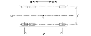
例えば、計量台22の長手方向の寸法、厳密には当該長手方向に沿って配置された2つのロードセルLCaおよびLCd間(またはLCbおよびLCc間)の寸法Aは、図4に示すトラックの前後の車輪間隔A’に合わせて設計されており、詳しくは当該前後の車輪間隔A’よりも少し大きめに設計されている。一方、図3において計量台22の短辺に沿う方向の寸法、厳密には当該短辺に沿って配置された2つのロードセルLCaおよびLCb間(またはLCcおよびLCd間)の寸法Bは、図4に示すトラックの左右の車輪間隔B’に合わせて設計されおり、詳しくは当該左右の車輪間隔B’よりも少し大きめに設計されている。ただし、トラックの前後の車輪間隔A’は、左右の車輪間隔B’に比べて、車種間での差異が大きいため、様々な車種に対応可能とするべく、計量台22の長手方向の寸法、言わば長さ寸法Aは、当該計量台22の短辺に沿う方向の寸法、言わば幅寸法Bに比べて、大きな余裕を持って設計されている。
For example, the dimension of the weighing table 22 in the longitudinal direction, strictly speaking, the dimension A between the two load cells LCa and LCd (or between LCb and LCc) arranged along the longitudinal direction is the front and rear of the track shown in FIG. It is designed in accordance with the wheel interval A ′, and specifically, is designed to be slightly larger than the front and rear wheel intervals A ′. On the other hand, the dimension in the direction along the short side of the weighing
このように計量台22の長さ寸法Aは幅寸法Bに比べて余裕を持って設計されているので、かかる計量台22に対して上述した要領でトラックが乗り入れられる際には、当該計量台22の幅方向(短辺に沿う方向)においては、トラックの載置位置は大きく変わらない、換言すれば変わりようがないが、計量台22の長さ方向(長手方向)においては、幅方向に比べて、トラックの載置位置が大きく変わる可能性がある。この点に注目すると、計量台22におけるトラックの載置位置は、当該計量台22の長さ方向においてのみ変わり、それ以外の方向には変わらない、という前提を立てることができる。別の言い方をすれば、図4に示すように、トラックの重心Gが概ね当該トラックの中心線(詳しくはトラックの左右の車輪間隔B’を二等分しかつ当該トラックの前後方向に沿って延伸する中心線)L0上にある、とすると、当該トラックの重心Gはまた計量台22の第1の中心線L1上にある、という前提を立てることができる。
Thus, since the length dimension A of the weighing table 22 is designed with a margin as compared with the width dimension B, when the truck enters the weighing table 22 in the manner described above, the weighing table 22 In the width direction of 22 (direction along the short side), the placement position of the track does not change greatly, in other words, it does not change, but in the length direction (longitudinal direction) of the weighing table 22, Compared to this, there is a possibility that the placement position of the track changes significantly. Paying attention to this point, it can be assumed that the track mounting position on the weighing
この前提の下、計量台22の上面(載置面)に、図5に示すような1次元座標系が設定される。具体的には、トラックの乗り入れ側(図5において左側)に配置された2つのロードセルLCaおよびLCbを結ぶ線分と、第1の中心線L1と、の交点Zに、原点が設定される。そして、この原点Zを通り、かつ第1の中心線L1に沿って延伸するように、基準線としてのx軸が設定される。なお、このx軸は、計量台22の中心である基準位置Oをも通ることになる。 Under this premise, a one-dimensional coordinate system as shown in FIG. 5 is set on the upper surface (mounting surface) of the weighing table 22. Specifically, the origin is set at the intersection Z between the line segment connecting the two load cells LCa and LCb arranged on the truck entry side (left side in FIG. 5) and the first center line L1. Then, the x axis as the reference line is set so as to extend along the first center line L1 through the origin Z. The x axis also passes through the reference position O, which is the center of the weighing table 22.
さらに、x軸上における原点Zと基準位置Oとの中間点Pに、代表位置が設定される。そして、基準位置Oを挟んで原点Zと反対側にある点、言わば当該原点Zと共役関係にある点Z’と、基準位置Oと、の中間点Qにも、代表位置が設定される。つまり、原点Zから共役点Z’に向かって、x軸上に、代表位置P,基準位置Oおよび代表位置Qが、この順番で等間隔に設定される。 Further, a representative position is set at an intermediate point P between the origin Z and the reference position O on the x axis. A representative position is also set at an intermediate point Q between the reference position O and a point on the opposite side of the origin Z across the reference position O, that is, a point Z 'that is conjugate with the origin Z. That is, the representative position P, the reference position O, and the representative position Q are set at equal intervals in this order on the x axis from the origin Z toward the conjugate point Z ′.
ここで、基準位置Oにおけるx軸の値をxoとし、この値xoを、計量台22の長さ寸法Aを用いて表すと、xo=A/2となる。そして、原点Zに近い側の代表位置Pにおけるx軸の値をxpとすると、xp=A/4となる。さらに、原点Zから遠い側の代表位置Qにおけるx軸の値をxqとすると、xq={3/4}・Aとなる。なお、原点Zにおけるx軸の値は、言うまでもなくx=0であり、共役点Z’におけるx軸の値は、x=Aとなる。 Here, when the value of the x-axis at the reference position O is xo, and this value xo is expressed using the length dimension A of the weighing table 22, xo = A / 2. If the x-axis value at the representative position P near the origin Z is xp, xp = A / 4. Further, if the value of the x-axis at the representative position Q far from the origin Z is xq, xq = {3/4} · A. Needless to say, the x-axis value at the origin Z is x = 0, and the x-axis value at the conjugate point Z ′ is x = A.
このようにして計量台22にx軸を含む1次元座標系が設定されると共に、当該x軸上に基準位置Oと2つの代表位置PおよびQとが設定された上で、上述した入力器38の操作によって調整モードが選択され、調整作業が行われる。 In this way, a one-dimensional coordinate system including the x axis is set on the weighing table 22, and the reference position O and the two representative positions P and Q are set on the x axis. The adjustment mode is selected by the operation of 38, and adjustment work is performed.
この調整作業においては、まず、最初に、上述したスパン係数Sを設定するべく、既知重量Mの基準分銅が、計量台22の基準位置Oに載置される。なお、基準分銅の重量Mは、トラックスケール10の秤量にもよるが、例えば当該秤量の半分程度とされ、詳しくは5[t]〜20[t]の範囲で適宜決定される。そして、かかる基準分銅が基準位置Oに載置された状態で、上述の式1に基づいて求められる重量測定値Wn’が基準分銅の重量Mと等価になるように、つまり次の式2が成立するように、スパン係数Sが設定される。
In this adjustment operation, first, a reference weight having a known weight M is placed at the reference position O of the weighing table 22 in order to set the span coefficient S described above. Note that the weight M of the reference weight depends on the weight of the
《式2》
Wn’=(Wa+Wb+Wc+Wd)・S=M
<<
Wn ′ = (Wa + Wb + Wc + Wd) · S = M
この式2に基づいて設定されたスパン係数Sは、メモリ回路40に記憶される。
The span coefficient S set based on
続いて、基準分銅が、基準位置Oから代表位置Pに移される。そして、この代表位置Pに基準分銅が載置されている状態で、上述の式1に基づいて重量測定値Wn’が算出される。なお、これ以降、当該式1に基づく重量測定値Wn’の算出には、上述の式2に基づいて設定されたスパン係数Sが適用される。そして、この式1に基づいて算出された重量測定値Wn’は、代表位置Pに基準分銅が載置されているときの測定値Mpとして、メモリ回路40に記憶される。
Subsequently, the reference weight is moved from the reference position O to the representative position P. Then, in a state where the reference weight is placed at the representative position P, the weight measurement value Wn ′ is calculated based on the above-described
ここで、この代表位置Pに基準分銅が載置されているときの重量測定値Mpと、基準位置Oに当該基準分銅が載置されているときの重量測定値Mとは、等価ではなく、これら両者の間には、次の式3で表される誤差Epが生じる。 Here, the weight measurement value Mp when the reference weight is placed at the representative position P and the weight measurement value M when the reference weight is placed at the reference position O are not equivalent, Between these two, an error Ep expressed by the following Expression 3 occurs.
《式3》
Ep=Mp−M
<< Formula 3 >>
Ep = Mp-M
これは、基準分銅が基準位置Oから代表位置Pに移されることによって、計量台22の撓み方が変わり、ひいては式1におけるスパン係数Sが変化するからである。つまり、基準分銅の載置位置が基準位置Oから代表位置Pに変わることによって、式1に基づいて求められる重量測定値Wn’に、式3で表される測定誤差Epが生じることになる。
This is because when the reference weight is moved from the reference position O to the representative position P, the way in which the weighing table 22 bends changes, and consequently, the span coefficient S in
さらにここで、x軸上の代表位置Pから基準位置Oまでの間の任意の位置に基準分銅が載置されたときの測定誤差をEpo(x)とし、この測定誤差Epo(x)が、当該x軸上における基準分銅の載置位置の変化に対して略直線的(略比例的)に変化する、と仮定する。すると、この測定誤差Epo(x)は、次の式4で表される。
Further, here, the measurement error when the reference weight is placed at an arbitrary position between the representative position P on the x-axis and the reference position O is Epo (x), and this measurement error Epo (x) is It is assumed that the reference weight changes substantially linearly (substantially proportionally) with respect to the change of the reference weight placement position on the x-axis. Then, this measurement error Epo (x) is expressed by the
《式4》
Epo(x)={(Mp−M)/(xp−xo)}・x−{(Mp−M)・xo/(xp−xo)}
={(Mp−M)/(xp−xo)}・(x−xo)
<<
Epo (x) = {(Mp-M) / (xp-xo)}. X-{(Mp-M) .xo / (xp-xo)}
= {(Mp-M) / (xp-xo)}. (X-xo)
そしてさらに、基準分銅に代えて、任意の重量Wnのトラックが、x軸上の代表位置Pから基準位置Oまでの間の任意の位置に載置される、と仮定し、このときの測定誤差Epo(x,Wn)が、当該トラックの重量Wnと略比例関係を示す、とする。すると、この測定誤差Epo(x,Wn)は、次の式5で表される。 Further, it is assumed that a track having an arbitrary weight Wn is placed at an arbitrary position between the representative position P and the reference position O on the x-axis in place of the reference weight. It is assumed that Epo (x, Wn) is substantially proportional to the weight Wn of the track. Then, this measurement error Epo (x, Wn) is expressed by the following equation 5.
《式5》
Epo(x,Wn)=Epo(x)・(Wn/M)
<< Formula 5 >>
Epo (x, Wn) = Epo (x) · (Wn / M)
つまり、この式5によれば、任意の重量Wnのトラックがx軸上の代表位置Pから基準位置Oまでの間の任意の位置に載置されているときに予想される測定誤差Epo(x,Wn)を、求めることができる。 That is, according to Equation 5, the measurement error Epo (x expected when a track having an arbitrary weight Wn is placed at an arbitrary position between the representative position P and the reference position O on the x axis. , Wn) can be determined.
ただし、この式5に含まれる重量Wnは、未知数であるため、現実には、当該式5によって真の測定誤差Epo(x,Wn)を求めることはできない。そこで、この式5に含まれる真の重量Wnに代えて、上述の式1で求められる重量測定値Wn’を適用する。これによって、次の式6が導き出される。
However, since the weight Wn included in Equation 5 is an unknown number, in reality, the true measurement error Epo (x, Wn) cannot be obtained by Equation 5. Therefore, instead of the true weight Wn included in Equation 5, the weight measurement value Wn ′ obtained by
《式6》
Epo(x,Wn’)=Epo(x)・(Wn’/M)≒Epo(x,Wn)
<< Formula 6 >>
Epo (x, Wn ′) = Epo (x) · (Wn ′ / M) ≈Epo (x, Wn)
このようにして導き出された式6、言わば測定誤差Epo(x,Wn)を推定するための誤差推定式は、メモリ回路40に記憶される。
The equation 6 thus derived, that is, the error estimation equation for estimating the measurement error Epo (x, Wn) is stored in the
次いで、今度は、代表位置Pに載置されていた基準分銅が、別の代表位置Qに移される。そして、この状態で、上述の式1に基づいて重量測定値Wn’が算出され、算出された重量測定値Wn’は、代表位置Qに基準分銅が載置されているときの測定値Mqとして、メモリ回路40に記憶される。なお、このように別の代表位置Qに基準分銅が載置されているときも、代表位置Pに当該基準分銅が載置されているときと同様に、次の式7で表される測定誤差Eqが生じる。
Next, the reference weight placed at the representative position P is moved to another representative position Q. In this state, the weight measurement value Wn ′ is calculated based on the above-described
《式7》
Eq=Mq−M
<< Formula 7 >>
Eq = Mq-M
ここで、x軸上の基準位置Oから代表位置Qまでの間の任意の位置に基準分銅が載置されたときの測定誤差をEoq(x)とする。そして、この測定誤差Eoq(x)もまた、上述の式4で表される測定誤差Epo(x)と同様に、x軸上における基準分銅の載置位置の変化に対して略比例的に変化する、と仮定する。すると、この測定誤差Eoq(x)は、次の式8で表される。Here, the measurement error when the reference weight is placed at an arbitrary position between the reference position O and the representative position Q on the x-axis is defined as Eoq (x). And this measurement error Eoq (x) also changes substantially proportionally to the change in the mounting position of the reference weight on the x-axis, similarly to the measurement error Epo (x) represented by the above-mentioned
《式8》
Eoq(x)={−(Mq−M)/(xo−xq)}・x+{(Mq−M)・xo/(xo−xq)}
={(Mq−M)/(xo−xq)}・(xo−x)
<< Formula 8 >>
Eoq (x) = {-(Mq-M) / (xo-xq)}. X + {(Mq-M) .xo / (xo-xq)}
= {(Mq-M) / (xo-xq)}. (Xo-x)
さらにここで、基準分銅に代えて、任意の重量Wnのトラックが、x軸上の基準位置Oから代表位置Qまでの間の任意の位置に載置される、と仮定し、このときの測定誤差Eoq(x,Wn)が、当該トラックの重量Wnと略比例関係を示す、とする。すると、この測定誤差Eoq(x,Wn)は、次の式9で表される。
Further, here, it is assumed that a track having an arbitrary weight Wn is placed at an arbitrary position between the reference position O and the representative position Q on the x-axis in place of the reference weight. It is assumed that the error Eoq (x, Wn) is substantially proportional to the weight Wn of the track. Then, the measurement error Eoq (x, Wn) is expressed by the following
《式9》
Eoq(x,Wn)=Eoq(x)・(Wn/M)
<<
Eoq (x, Wn) = Eoq (x) · (Wn / M)
そして、この式9に含まれる真の重量Wnに代えて、上述の式1で求められる重量測定値Wn’を適用することによって、次の式10で表される誤差推定式が、導き出される。
Then, by applying the weight measurement value Wn ′ obtained by the above-described
《式10》
Eoq(x,Wn’)=Eoq(x)・(Wn’/M)≒Eoq(x,Wn)
<<
Eoq (x, Wn ′) = Eoq (x) · (Wn ′ / M) ≈Eoq (x, Wn)
この式10で表される誤差推定式もまた、メモリ回路40に記憶される。
The error estimation expression expressed by
これで、調整モードによる一連の調整作業が終了し、実際の測定作業が可能となる。なお、調整作業の終了後は、計量台22から基準分銅が降ろされる。
This completes a series of adjustment operations in the adjustment mode, and actual measurement operations are possible. In addition, after completion | finish of adjustment work, a reference | standard weight is dropped from the weighing
実際の測定作業に入るには、まず、入力器24の操作によって稼働モードが選択される。そして、図3に示した要領で、計量台22にトラックが乗り入れられ、載置される。すると、上述したように、トラックの重量Wnに応じた荷重が、各ロードセルLCa,LCb,LCcおよびLCdに分散して印加される。そして、これら各ロードセルLCa,LCb,LCcおよびLCdの出力値Wa,Wb,WcおよびWdを含む上述の式1に基づいて、トラックの重量測定値Wn’が求められる。
To enter the actual measurement work, first, the operation mode is selected by operating the
これと併せて、各ロードセルLCa,LCb,LCcおよびLCdの出力値Wa,Wb,WcおよびWdと、当該各ロードセルLCa,LCb,LCcおよびLCdの相互の位置関係と、に基づいて、計量台22におけるトラックの載置位置が検出される。具体的には、次の式11に基づいて、上述したx軸上におけるトラックの重心Gの座標xが求められる。 At the same time, the weighing table 22 is based on the output values Wa, Wb, Wc and Wd of the load cells LCa, LCb, LCc and LCd and the positional relationship between the load cells LCa, LCb, LCc and LCd. The track placement position at is detected. Specifically, the coordinate x of the center of gravity G of the track on the x-axis described above is obtained based on the following equation (11).
《式11》
x={(Wc+Wd)/(Wa+Wb+Wc+Wd)}・A
<< Formula 11 >>
x = {(Wc + Wd) / (Wa + Wb + Wc + Wd)} · A
このようにしてトラックの重心Gの座標xが検出された後、さらに、この座標xが計量台22の基準位置Oよりも乗り入れ側(つまりロードセルLCaおよびLCb側)にあるのか、それとも降車側(つまりロードセルLCcおよびLCd側)にあるのかが、判定される。ここで、例えば、当該座標xが計量台22の基準位置Oよりも乗り入れ側にある場合、詳しくはx<A/2の場合は、上述した式6の誤差推定式に基づいて、測定誤差Epo(x,Wn)が推定され、言わば推定誤差Epo(x,Wn’)が算出される。ただし、座標xが乗り入れ側の代表位置Pよりもさらに当該乗り入れ側にある場合、つまりx<A/4の場合は、当該座標xにA/4が代入された上で、推定誤差Epo(x,Wn’)が算出される。そして、算出された推定誤差Epo(x,Wn’)を、上述の式1によって求められた重量測定値Wn’から差し引くことで、つまり次の式12に基づいて、当該推定誤差Epo(x,Wn’)分が補正された補正後重量値Wn”が求められる。
After the coordinate x of the center of gravity G of the truck is thus detected, whether the coordinate x is further on the entry side (that is, on the load cell LCa and LCb side) than the reference position O of the weighing table 22, or on the getting-off side ( That is, it is determined whether it is on the load cell LCc and LCd side). Here, for example, when the coordinate x is on the entry side with respect to the reference position O of the weighing table 22, more specifically, when x <A / 2, the measurement error Epo is based on the error estimation equation of Equation 6 described above. (X, Wn) is estimated, that is, an estimation error Epo (x, Wn ′) is calculated. However, when the coordinate x is further on the entry side than the representative position P on the entry side, that is, when x <A / 4, the estimation error Epo (x , Wn ′) is calculated. Then, the estimated error Epo (x, Wn ′) calculated is subtracted from the weight measurement value Wn ′ obtained by the above-described
《式12》
Wn”=Wn’−Epo(x,Wn’)
<< Formula 12 >>
Wn ″ = Wn′−Epo (x, Wn ′)
なお、この式12の右辺に含まれる推定誤差Epo(x,Wn’)は、重量測定値Wn’に基づいて求められたものであり、つまり測定誤差Epo(x,Wn)成分を含む。従って、かかる測定誤差Epo(x,Wn)成分を含む式12に基づいて求められた補正後重量値Wn”は、真の重量Wnとは一致せず、これら両者Wn”およびWnの間には、次の式13で表される誤差ΔEpoが生じる。 Note that the estimation error Epo (x, Wn ′) included in the right side of Equation 12 is obtained based on the weight measurement value Wn ′, that is, includes a measurement error Epo (x, Wn) component. Accordingly, the corrected weight value Wn ″ obtained based on the equation 12 including the measurement error Epo (x, Wn) component does not coincide with the true weight Wn, and between these two values Wn ″ and Wn. Then, an error ΔEpo expressed by the following equation 13 occurs.
《式13》
ΔEpo=Wn”−Wn=Epo(x,Wn)−Epo(x,Wn’)
<< Formula 13 >>
ΔEpo = Wn ″ −Wn = Epo (x, Wn) −Epo (x, Wn ′)
しかしながら、測定誤差Epo(x,Wn)は、重量測定値Wn’に比べて極めて小さく、例えば最大でも当該重量測定値Wn’の0.05[%]程度である。従って、かかる極小の測定誤差Epo(x,Wn)成分を含む重量測定値Wn’に基づいて求められた推定誤差Epo(x,Wn’)と、真の測定誤差Epo(x,Wn)と、の差、つまり式13で表される誤差ΔEpoは、さらに小さくなる。ゆえに、式12に基づいて求められる補正後重量値Wn”によっても、十分に実用的な測定精度を得ることができ、例えば真の重量Wnに対する誤差ΔEpoの割合が±0.01[%]以下という高い測定精度を得ることができる。 However, the measurement error Epo (x, Wn) is extremely smaller than the weight measurement value Wn ′, and is, for example, about 0.05 [%] of the weight measurement value Wn ′ at the maximum. Therefore, an estimation error Epo (x, Wn ′) obtained based on the weight measurement value Wn ′ including such a minimum measurement error Epo (x, Wn) component, a true measurement error Epo (x, Wn), , That is, the error ΔEpo expressed by Expression 13 is further reduced. Therefore, a sufficiently practical measurement accuracy can also be obtained by the corrected weight value Wn ″ obtained based on Expression 12, for example, the ratio of the error ΔEpo to the true weight Wn is ± 0.01 [%] or less. High measurement accuracy can be obtained.
一方、上述の式11に基づいて検出された座標xが、計量台22の基準位置Oにあるか、若しくは当該基準位置Oよりも降車側にある場合、つまりx≧A/2の場合は、上述した式10の誤差推定式に基づいて、測定誤差Eoq(x,Wn)が推定され、つまり推定誤差Eoq(x,Wn’)が算出される。ただし、座標xが降車側の代表位置Qよりもさらに当該降車側にある場合、つまりx>{3・4}・Aの場合は、当該座標xに{3・4}・Aが代入された上で、推定誤差Eoq(x,Wn’)が算出される。そして、算出された推定誤差Eoq(x,Wn’)を、式1によって求められた重量測定値Wn’から差し引くことで、つまり次の式14に基づいて、当該推定誤差Eoq(x,Wn’)分が補正された補正後重量値Wn”が求められる。
On the other hand, when the coordinate x detected based on the above equation 11 is at the reference position O of the weighing table 22 or on the getting-off side from the reference position O, that is, when x ≧ A / 2, The measurement error Eoq (x, Wn) is estimated based on the error estimation formula of the above-described
《式14》
Wn”=Wn’−Eoq(x,Wn’)
<< Formula 14 >>
Wn ″ = Wn′−Eoq (x, Wn ′)
なお、この式14に基づいて求められる補正後重量値Wn”もまた、上述の式13と同様、次の式15で表される誤差ΔEoqを含むが、この誤差ΔEoqは極めて小さいので、十分な測定精度を得ることができる。 The corrected weight value Wn ″ obtained based on this equation 14 also includes the error ΔEoq expressed by the following equation 15 as in the above-described equation 13, but this error ΔEoq is extremely small, Measurement accuracy can be obtained.
《式15》
ΔEoq=Wn”−Wn=Eoq(x,Wn)−Eoq(x,Wn’)
<< Formula 15 >>
ΔEoq = Wn ″ −Wn = Eoq (x, Wn) −Eoq (x, Wn ′)
そして、このようにして式12または式14に基づいて求められた補正後重量値Wn”は、上述したように表示器36に表示される。
The corrected weight value Wn ″ thus obtained based on the formula 12 or the formula 14 is displayed on the
次に、図6を参照しながら、上述した調整モードによる調整作業の手順について、改めて説明する。 Next, the procedure of the adjustment work in the adjustment mode described above will be described again with reference to FIG.
まず、最初のステップS1として、計量台22の基準位置Oに基準分銅が載置される。そして、この状態で、スパン調整が行われ、つまり上述の式2が成立するようにスパン係数Sが設定される。そして、設定されたスパン係数Sは、メモリ回路40に記憶される。
First, as a first step S <b> 1, a reference weight is placed at the reference position O of the weighing table 22. In this state, span adjustment is performed, that is, the span coefficient S is set so that the above-described
続いて、ステップS3において、基準位置Oに載置されている基準分銅が、代表位置Pに移される。そして、この状態で、重量測定が行われ、つまり上述の式1に基づいて重量測定値Wn’が算出される。そして、算出された重量測定値Wn’は、代表位置Pに基準分銅が載置されているときの測定値Maとして、メモリ回路40に記憶される。
Subsequently, in step S3, the reference weight placed at the reference position O is moved to the representative position P. In this state, the weight measurement is performed, that is, the weight measurement value Wn ′ is calculated based on the above-described
さらに、続くステップS5において、上述した式6、つまりトラックの重心Gが代表位置Pから基準位置Oまでの間の任意の位置にあるときの測定誤差Epo(x,Wn)を推定するための誤差推定式が、導き出される。そして、導き出された誤差推定式は、メモリ回路40に記憶される。
Further, in the following step S5, the above-described equation 6, that is, an error for estimating the measurement error Epo (x, Wn) when the track's center of gravity G is at an arbitrary position between the representative position P and the reference position O. An estimation formula is derived. Then, the derived error estimation formula is stored in the
このステップS5の実行後、次のステップS7において、代表位置Pに載置されている基準分銅が、別の代表位置Qに移される。そして、この状態で、重量測定が行われ、つまり式1に基づいて重量測定値Wn’が算出される。そして、算出された重量測定値Wn’は、代表位置Qに基準分銅が載置されているときの測定値Mqとして、メモリ回路40に記憶される。
After execution of step S5, the reference weight placed at the representative position P is moved to another representative position Q in the next step S7. In this state, weight measurement is performed, that is, the weight measurement value Wn ′ is calculated based on
次いで、ステップS9において、上述した式10、つまりトラックの重心Gが基準位置Oから代表位置Qまでの間の任意の位置にあるときの測定誤差Eoq(x,Wn)を推定するための誤差推定式が、導き出される。そして、導き出された誤差推定式は、メモリ回路40に記憶される。
Next, in step S9,
このステップS9の実行をもって、一連の調整作業が終了する。そして、この調整作業の終了後、計量台12から基準分銅が取り除かれる。 With the execution of step S9, a series of adjustment work is completed. Then, after this adjustment operation is completed, the reference weight is removed from the weighing table 12.
続いて、図7を参照して、稼働モードにおけるCPU34の動作について、説明する。
Next, the operation of the
即ち、各ロードセルLCa,LCb,LCcおよびLCdからそれぞれの出力値Wa,Wb,WcおよびWdを取得するタイミングが到来すると、CPU34は、ステップS11に進み、当該出力値Wa,Wb,WcおよびWdを取得する。なお、これらの出力値Wa,Wb,WcおよびWdの取得タイミングは、各ロードセルLCa,LCb,LCcおよびLCdのサンプリング周期に合わせて到来し、例えば1[ms]周期で到来する。
That is, when the timing for obtaining the output values Wa, Wb, Wc, and Wd from the load cells LCa, LCb, LCc, and LCd comes, the
そして、CPU34は、ステップS13に進み、上述した式1に基づいてトラックの重量測定値Wn’を算出した後、さらに、ステップS15に進み、上述の式11に基づいて、当該トラックの重心Gの座標xを求める。そして、ステップS17において、このトラックの重心Gの座標xが乗り入れ側の代表位置Pよりもさらに当該乗り入れ側にあるか否か、つまりx<A/4であるか否か、を判定する。
Then, the
ここで、例えば、トラックの重心Gの座標xが代表位置Pよりも乗り入れ側にある場合、つまりx<A/4である場合、CPU34は、ステップS19に進む。そして、このステップS19において、当該座標xにA/4を代入した後、ステップS21に進む。
Here, for example, if the coordinate x of the center of gravity G of the track is closer to the entry side than the representative position P, that is, if x <A / 4, the
ステップS21において、CPU34は、上述した式6に基づいて、測定誤差Epo(x,Wn)を推定し、つまり推定誤差Epo(x,Wn’)を算出する。さらに、ステップS23に進み、上述した式12に基づいて、補正後重量値Wn”を算出する。そして、続くステップS25において、当該補正後重量値Wn”を表示器36に表示した後、一旦、この図7のフローチャートで示されるタスクを終了する。
In step S <b> 21, the
一方、上述のステップS17において、トラックの重心Gの座標xが代表位置Pから降車側にあると判定した場合、つまりx≧A/4である場合、CPU34は、ステップS27に進む。そして、このステップS27において、さらに当該座標xが基準位置Oよりも乗り入れ側にあるか否か、つまりx<A/2であるか否か、を判定する。
On the other hand, if it is determined in step S17 described above that the coordinate x of the center of gravity G of the track is on the side of getting off from the representative position P, that is, if x ≧ A / 4, the
ここで、トラックの重心Gの座標xが基準位置Oよりも乗り入れ側にある場合、つまりx<A/2である場合、CPU34は、上述のステップS21に進む。これに対して、当該座標xが基準位置Oから降車側にある場合、つまりx≧A/2である場合は、ステップS29に進む。
Here, when the coordinate x of the center of gravity G of the track is closer to the entry side than the reference position O, that is, when x <A / 2, the
ステップS29において、CPU34は、トラックの重心Gの座標xが降車側の代表位置Qを含め当該代表位置Qから乗り入れ側にあるか否か、つまりx≦{3/4}・Aであるか否か、を判定する。そして、例えば、当該座標xが代表位置Qから乗り入れ側にある場合、つまりx≦{3/4}・Aである場合は、ステップS31に進む。
In step S29, the
ステップS31において、CPU34は、上述した式10に基づいて、測定誤差Eoq(x,Wn)を推定し、つまり推定誤差Eoq(x,Wn’)を算出する。そして、ステップS33に進み、上述した式14に基づいて、補正後重量値Wn”を算出した後、ステップS25に進む。
In step S31, the
一方、ステップS29において、トラックの重心Gの座標xが代表位置Qよりも降車側にある場合、つまりx>{3/4}・Aである場合、CPU34は、ステップS35に進む。そして、このステップS35において、当該座標xに{3/4}・Aを代入した後、ステップS31に進む。
On the other hand, if the coordinate x of the center of gravity G of the track is on the getting-off side from the representative position Q in step S29, that is, if x> {3/4} · A, the
以上のように、この実施形態のトラックスケール10によれば、計量台22におけるトラックの載置位置に起因するスパン変化のみならず、当該トラックの重量Wnに起因するスパン変化をも考慮して誤差補正が行われる。従って、被計量物の載置位置についてのみ考慮され、被計量物の重量については何ら考慮されずに誤差補正が行われる上述の従来技術に比べて、より正確な誤差補正を実現することができる。
As described above, according to the
併せて、この実施形態では、計量台22の長手方向においてのみトラックの載置位置が大きく変動するというトラックスケール10の性質に着目して、当該計量台22の長手方向に沿って設定されたx軸上にトラックの重心Gが位置するという前提を立て、この前提の下、誤差補正が行われる。詳しくは、x軸上に、基準位置Oと2つの代表位置PおよびQとが設定される。そして、事前の調整作業において、これら3箇所に個別に基準分銅が載置され、そのときに得られる重量測定値M,MpおよびMqに基づいて、上述した式6および式10で表される2つの誤差推定式が導き出される。これに対して、従来技術では、計量台全体にわたって被計量物の載置位置が変わることを前提としているがために、計量台に9つもの代表位置が言わば2次元的に設定される。そして、事前の調整作業において、これら9の代表位置に個別に基準分銅が載置され、このときに得られるロードセルの出力値に基づいて、それぞれの代表位置ごとのスパン係数、つまり9つのスパン係数、が求められ、さらに、これら9つのスパン係数に基づいて、計量台の任意の位置に対応するスパン係数を推定するための推定式が求められる。このことから明らかなように、この実施形態によれば、従来技術に比べて、事前の調整作業で基準分銅を積み降ろしする手間が大幅に軽減されると共に、誤差補正を実現するための演算も簡素化される。
In addition, in this embodiment, paying attention to the property of the
即ち、この実施形態によれば、従来よりも簡素な演算であるにも拘らず、スパン変化に起因する測定誤差をより正確に補正することができ、しかも事前の調整作業に掛かるコストを大幅に低減することができる。 That is, according to this embodiment, it is possible to correct the measurement error due to the span change more accurately in spite of the simpler calculation than the conventional one, and the cost for the prior adjustment work is greatly increased. Can be reduced.
なお、この実施形態においては、荷重検出手段として、ディジタル式のロードセルLCa、LCb,LCcおよびLCdを採用したが、これに代えて、アナログ式のロードセルを採用してもよい。ただし、この場合は、ロードセルから出力されるアナログ荷重検出信号をディジタル荷重検出信号に変換するための変換回路が、必要になる。 In this embodiment, digital load cells LCa, LCb, LCc, and LCd are employed as the load detection means. However, instead of this, analog load cells may be employed. However, in this case, a conversion circuit for converting the analog load detection signal output from the load cell into a digital load detection signal is required.
また、各ロードセルLCa、LCb,LCcおよびLCdを計量台22の4隅に配置したが、これ以外の場所に適宜配置してもよい。さらに、ロードセルLCa、LCb,LCcおよびLCdの数は、4つに限らず、これ以外の複数としてもよいし、極端には1つであってもよい。
Moreover, although each load cell LCa, LCb, LCc, and LCd was arrange | positioned in the four corners of the weighing
そして、上述した式11に基づいて、計量台22におけるトラックの重心Gの座標xを検出したが、これに代えて、次の式16に基づいて当該座標xを検出してもよい。 Then, the coordinate x of the center of gravity G of the track on the weighing table 22 is detected based on the above-described equation 11, but instead, the coordinate x may be detected based on the following equation 16.
《式16》
x={1−(Wa+Wb)/(Wa+Wb+Wc+Wd)}・A
<< Formula 16 >>
x = {1− (Wa + Wb) / (Wa + Wb + Wc + Wd)} · A
さらに、この式16と上述した式11と平均によって、当該座標xを検出してもよい。 Further, the coordinate x may be detected by the equation 16 and the above equation 11 and the average.
また、これら式11および式16に基づくのではなく、つまり各ロードセルLCa、LCb,LCcおよびLCdの出力値Wa,Wb、WcおよびWdと当該各ロードセルLCa、LCb,LCcおよびLC4の相互の位置関係とに基づくのではなく、光センサ等の別の位置検出手段によって、トラックの重心Gの座標xを検出してもよい。ただし、かかる別の位置検出手段を設けることによって、その分、トラックスケール10全体の構成が複雑化し、かつ高コスト化することは、言うまでもない。
Further, the positional relationship between the load cells LCa, LCb, LCc, and LC4 and the output values Wa, Wb, Wc, and Wd of the load cells LCa, LCb, LCc, and LCd is not based on the equations 11 and 16. The coordinates x of the center of gravity G of the track may be detected by another position detection means such as an optical sensor. However, it goes without saying that the provision of such another position detection means complicates the overall configuration of the
そしてさらに、この実施形態においては、上述の式5および式9で表される測定誤差Epo(x,Wn)およびEoq(x,Wn)が、トラックの重量Wnと略比例関係にあると仮定したが、計量台22の構造によっては、当該トラックの重量Wnに対して指数関数的に、例えば2乗で、変化する場合がある。このような場合は、上述した式6および式10の誤差推定式に代えて、次の式17および式18に基づいて、当該測定誤差Epo(x,Wn)およびEoq(x,Wn)を推定するのが、望ましい。
Further, in this embodiment, it is assumed that the measurement errors Epo (x, Wn) and Eoq (x, Wn) represented by the above-described
《式17》
Epo(x,Wn’)=Epo(x)・(Wn’/M)2
<Equation 17>
Epo (x, Wn ′) = Epo (x) · (Wn ′ / M) 2
《式18》
Eoq(x,Wn’)=Eoq(x)・(Wn’/M)2
<< Formula 18 >>
Eoq (x, Wn ′) = Eoq (x) · (Wn ′ / M) 2
さらにまた、Wn’/M=rと置き、この言わば重量比rがトラックの重量Wnに対してどのように変化するのかを解析し、その解析結果を誤差推定式に適用してもよい。具体的には、事前の調整作業において、上述した各代表位置PおよびQのそれぞれに載置される基準分銅の重量Mをいくつか変更しながら、当該各代表位置PおよびQのそれぞれにおける重量比rの変化を調べる。そして、公知の最小自乗法またはその他の方法によって、当該各代表位置PおよびQのそれぞれにおける重量比rの変化を、fp(r)およびfq(r)という関数で表す。そして、この関数fp(r)およびfq(r)がそれぞれ適用された次の式19および式20に基づいて、測定誤差Epo(x,Wn)およびEoq(x,Wn)を推定してもよい。
Furthermore, Wn ′ / M = r may be set, and in other words, how the weight ratio r changes with respect to the weight Wn of the truck may be analyzed, and the analysis result may be applied to the error estimation formula. Specifically, in the pre-adjustment operation, the weight ratio at each of the representative positions P and Q is changed while changing the weight M of the reference weight placed at each of the representative positions P and Q described above. Examine changes in r. Then, the change in the weight ratio r at each of the representative positions P and Q is expressed by a function of fp (r) and fq (r) by a known least square method or other methods. The measurement errors Epo (x, Wn) and Eoq (x, Wn) may be estimated based on the following
《式17》
Epo(x,Wn’)=Epo(x)・fp(r)
<Equation 17>
Epo (x, Wn ′) = Epo (x) · fp (r)
《式18》
Eoq(x,Wn’)=Eoq(x)・fq(r)
<< Formula 18 >>
Eoq (x, Wn ′) = Eoq (x) · fq (r)
なお、上述の如く基準分銅の重量Mをいくつか変更することによって、当該基準分銅を積み降ろしする手間が増えるのではないかと、懸念される。しかしながら、上述したように基準分銅の重量Mは数[t]程度もあるので、かかる重量Mが数[t]程度もある基準分銅が一遍に積み降ろされることはなく、通常は、何回かに分けて積み降ろしが行われる。従って、この積み降ろしの過程で上述の重量比rの変化を解析することができるので、当該解析のために余分な手間が増えることはない。 In addition, there is a concern that changing the weight M of the reference weight as described above may increase the labor for loading and unloading the reference weight. However, since the weight M of the reference weight is about several [t] as described above, the reference weight having the weight M of about several [t] is not loaded and unloaded all the time, usually several times. The loading and unloading will be carried out. Accordingly, since the change in the weight ratio r can be analyzed during the loading / unloading process, no extra effort is required for the analysis.
また、この実施形態においては、測定誤差Epo(x,Wn)およびEoq(x,Wn)が、トラックの重心Gの座標xの変化に対して略比例的に変化すると仮定したが、計量台22の構造によっては、当該トラックの重量Wnに対して指数関数的に、例えば2次的に、変化する場合がある。このような場合は、当該測定誤差Epo(x,Wn)およびEoq(x,Wn)を2次方程式で表してもよい。特に、代表位置PおよびQに加えて、さらに多くの代表位置を設定すると共に、これら各代表位置における測定誤差を解析すれば、より正確な誤差補正を実現することができる。 In this embodiment, it is assumed that the measurement errors Epo (x, Wn) and Eoq (x, Wn) change approximately proportionally to the change in the coordinate x of the center of gravity G of the track. Depending on the structure, there may be an exponential change with respect to the weight Wn of the track, for example, quadratic. In such a case, the measurement errors Epo (x, Wn) and Eoq (x, Wn) may be expressed by a quadratic equation. In particular, by setting more representative positions in addition to the representative positions P and Q, and analyzing the measurement error at each representative position, more accurate error correction can be realized.
さらに、測定誤差Epo(x,Wn)およびEoq(x,Wn)という誤差の値そのものではなく、例えば真の重量Wnに対する当該誤差の比率、言わば誤差率を求め、この誤差率に基づいて補正を行ってもよい。具体的には、上述した式3および式7に代えて、それぞれの代表位置PおよびQに基準分銅が載置されているときの誤差率を、Mp/MおよびMq/Mから求める。そして、この誤差率に基づいて、上述したx軸上の任意の位置に任意の重量Wnのトラックが載置されているときに予想される誤差率を推定するための誤差率推定式を導き出し、この誤差率推定式に基づいて求められた誤差率を重量測定値Wn’に乗ずることによって、補正後重量値Wn”を求める、つまり補正を行ってもよい。 Furthermore, instead of the error values themselves of measurement errors Epo (x, Wn) and Eoq (x, Wn), for example, a ratio of the error to the true weight Wn, that is, an error rate is obtained, and correction is performed based on the error rate. You may go. Specifically, the error rate when the reference weight is placed at each of the representative positions P and Q is obtained from Mp / M and Mq / M instead of the above-described Expression 3 and Expression 7. Then, based on this error rate, an error rate estimation formula for estimating an error rate expected when a track having an arbitrary weight Wn is placed at an arbitrary position on the x-axis described above is derived, The weight value Wn ″ after correction may be obtained by multiplying the weight measurement value Wn ′ by the error rate obtained based on the error rate estimation formula, that is, correction may be performed.
この実施形態では、トラックスケール10を例に挙げて説明したが、トラックスケール10以外の計量装置にもこの発明を適用できることは、言うまでもない。
In this embodiment, the
10 トラックスケール
20 計量部
22 計量台
24 ロードセル
30 データプロセッサ
34 CPU
10
Claims (5)
上記計量台を支持すると共に該計量台に被計量物が載置されることによって印加される荷重を検出する荷重検出手段と、
上記荷重検出手段の出力値に基づいて上記被計量物の重量を算出する重量算出手段と、
上記計量台における上記被計量物の載置位置が最も大きく変動する特定方向に関する該被計量物の載置位置を検出する位置検出手段と、
上記被計量物の重量および上記計量台における載置位置に応じて上記荷重検出手段のスパンが変化することに起因する該被計量物の重量と上記重量算出手段による算出重量値との差を該算出重量値および上記位置検出手段による検出位置に基づいて補正する補正手段と、
を具備する、計量装置。 A weighing platform;
Load detecting means for supporting the weighing table and detecting a load applied by placing an object to be weighed on the weighing table;
Weight calculating means for calculating the weight of the object to be measured based on the output value of the load detecting means;
Position detecting means for detecting the placement position of the object to be measured with respect to a specific direction in which the placement position of the object to be weighed on the weighing table varies the most
The difference between the weight of the object to be weighed due to the change in the span of the load detecting means according to the weight of the object to be weighed and the mounting position on the weighing table and the weight value calculated by the weight calculating means Correction means for correcting based on the calculated weight value and the position detected by the position detection means;
A weighing device.
上記計量台に設定された上記特定方向に沿う基準線上の互いに異なる複数の特定位置に個別に既知荷重が印加されたときの上記重量算出手段による算出重量値、および該複数の特定位置の位置関係、に基づいて、該基準線上の任意の位置に任意の重量の上記被計量物が載置されたときに予想される上記差を推定するための誤差推定式を導出する導出手段と、
上記重量算出手段による算出重量値および上記位置検出手段による検出位置を上記誤差推定式に適用することによって該算出重量値および該検出位置に対応する上記差を表す推定誤差を算出する誤差算出手段と、
上記推定誤差に基づいて補正を行う補正実行手段と、
を含む、請求項1に記載の計量装置。 The correction means is
Weight value calculated by the weight calculating means when a known load is individually applied to a plurality of different specific positions on a reference line along the specific direction set on the weighing platform, and a positional relationship between the plurality of specific positions Derivation means for deriving an error estimation formula for estimating the difference expected when the object to be weighed having an arbitrary weight is placed at an arbitrary position on the reference line based on
An error calculating means for calculating an estimated error indicating the calculated weight value and the difference corresponding to the detected position by applying the calculated weight value by the weight calculating means and the detected position by the position detecting means to the error estimation formula; ,
Correction execution means for performing correction based on the estimation error;
The metering device according to claim 1, comprising:
上記重量算出手段は上記複数の荷重検出手段の出力値の合計に基づいて算出を行う、
請求項1または2に記載の計量装置。 A plurality of load detection means,
The weight calculating means calculates based on the sum of output values of the plurality of load detecting means.
The weighing device according to claim 1 or 2.
請求項3に記載の計量装置。 The position detection means performs detection based on the output values of the plurality of load detection means and the positional relationship of the plurality of load detection means.
The weighing device according to claim 3.
Priority Applications (1)
| Application Number | Priority Date | Filing Date | Title |
|---|---|---|---|
| JP2006215566A JP4814005B2 (en) | 2006-08-08 | 2006-08-08 | Weighing device |
Applications Claiming Priority (1)
| Application Number | Priority Date | Filing Date | Title |
|---|---|---|---|
| JP2006215566A JP4814005B2 (en) | 2006-08-08 | 2006-08-08 | Weighing device |
Publications (2)
| Publication Number | Publication Date |
|---|---|
| JP2008039633A JP2008039633A (en) | 2008-02-21 |
| JP4814005B2 true JP4814005B2 (en) | 2011-11-09 |
Family
ID=39174806
Family Applications (1)
| Application Number | Title | Priority Date | Filing Date |
|---|---|---|---|
| JP2006215566A Active JP4814005B2 (en) | 2006-08-08 | 2006-08-08 | Weighing device |
Country Status (1)
| Country | Link |
|---|---|
| JP (1) | JP4814005B2 (en) |
Families Citing this family (2)
| Publication number | Priority date | Publication date | Assignee | Title |
|---|---|---|---|---|
| CN109855710B (en) * | 2019-03-11 | 2021-04-27 | 耿建航 | Truck scale weighing state monitoring system and detection method |
| CN111977233A (en) * | 2019-05-22 | 2020-11-24 | 深圳市瑞微智能有限责任公司 | Method, device and system for positioning material in and out of warehouse |
Family Cites Families (5)
| Publication number | Priority date | Publication date | Assignee | Title |
|---|---|---|---|---|
| JPS60236036A (en) * | 1984-05-09 | 1985-11-22 | Shimadzu Corp | Electronic balance |
| JPH0640017B2 (en) * | 1985-01-30 | 1994-05-25 | 株式会社島津製作所 | Electronic balance |
| JPH05312623A (en) * | 1992-05-06 | 1993-11-22 | Tokyo Electric Co Ltd | Electronic balance |
| JP4117759B2 (en) * | 2001-03-16 | 2008-07-16 | 株式会社クボタ | Multi-load cell type balance, offset error correction method |
| JP4012469B2 (en) * | 2003-01-24 | 2007-11-21 | 大和製衡株式会社 | Weighing device |
-
2006
- 2006-08-08 JP JP2006215566A patent/JP4814005B2/en active Active
Also Published As
| Publication number | Publication date |
|---|---|
| JP2008039633A (en) | 2008-02-21 |
Similar Documents
| Publication | Publication Date | Title |
|---|---|---|
| US9212888B2 (en) | Method for compensating measurement errors caused by deformations of a measuring machine bed under the load of a workpiece and measuring machine operating according to said method | |
| CN100595530C (en) | Weighing device, in particular multiple-track weighing device | |
| US20110301897A1 (en) | Calibration of a triaxial magnetic field sensor | |
| JP4642504B2 (en) | Weight measuring device | |
| EP3714240B1 (en) | Weighting method and storage medium thereof | |
| WO2006132235A1 (en) | Load cell-type electronic balance | |
| JP2011503628A (en) | Method for calibrating a coordinate measuring machine | |
| EP1239263A2 (en) | Position measuring apparatus and working apparatus using the same | |
| TWI506239B (en) | System and method for compensating temperature | |
| TW202026603A (en) | Electronic scale with correction function and correction method applied thereto | |
| EP1457768B1 (en) | Barycentric position measuring apparatus | |
| JP4814005B2 (en) | Weighing device | |
| JPH09128549A (en) | Relative position attitude detecting method for robot system | |
| Balsamo et al. | Results of the CIRP-Euromet intercomparison of ball plate-based techniques for determining CMM parametric errors | |
| JP4012469B2 (en) | Weighing device | |
| JP4763476B2 (en) | Inclination error determination device, inclination error determination method, measuring instrument, and measuring method | |
| JPH07205075A (en) | Weight compensation method of end effector at force control robot | |
| US20050261852A1 (en) | Calibration assisting method, device and system | |
| JP4813972B2 (en) | Weighing device | |
| JPH0746060B2 (en) | Electronic balance | |
| JP4444531B2 (en) | Simple inspection vehicle and calibration method thereof | |
| JP5679837B2 (en) | Weighing device | |
| US12044654B2 (en) | Measurement method for non-destructive inspection, measurement device, non-destructive inspection method, information processing device of non-destructive inspection, and recording medium | |
| KR102538936B1 (en) | Electronic scales with imporved precision | |
| JP2012163530A (en) | Measuring apparatus |
Legal Events
| Date | Code | Title | Description |
|---|---|---|---|
| A621 | Written request for application examination |
Free format text: JAPANESE INTERMEDIATE CODE: A621 Effective date: 20090630 |
|
| A977 | Report on retrieval |
Free format text: JAPANESE INTERMEDIATE CODE: A971007 Effective date: 20110819 |
|
| TRDD | Decision of grant or rejection written | ||
| A01 | Written decision to grant a patent or to grant a registration (utility model) |
Free format text: JAPANESE INTERMEDIATE CODE: A01 Effective date: 20110823 |
|
| A01 | Written decision to grant a patent or to grant a registration (utility model) |
Free format text: JAPANESE INTERMEDIATE CODE: A01 |
|
| A61 | First payment of annual fees (during grant procedure) |
Free format text: JAPANESE INTERMEDIATE CODE: A61 Effective date: 20110825 |
|
| R150 | Certificate of patent or registration of utility model |
Ref document number: 4814005 Country of ref document: JP Free format text: JAPANESE INTERMEDIATE CODE: R150 |
|
| FPAY | Renewal fee payment (event date is renewal date of database) |
Free format text: PAYMENT UNTIL: 20140902 Year of fee payment: 3 |
|
| R250 | Receipt of annual fees |
Free format text: JAPANESE INTERMEDIATE CODE: R250 |
|
| R250 | Receipt of annual fees |
Free format text: JAPANESE INTERMEDIATE CODE: R250 |
|
| R250 | Receipt of annual fees |
Free format text: JAPANESE INTERMEDIATE CODE: R250 |
|
| R250 | Receipt of annual fees |
Free format text: JAPANESE INTERMEDIATE CODE: R250 |
|
| R250 | Receipt of annual fees |
Free format text: JAPANESE INTERMEDIATE CODE: R250 |
|
| R250 | Receipt of annual fees |
Free format text: JAPANESE INTERMEDIATE CODE: R250 |
|
| R250 | Receipt of annual fees |
Free format text: JAPANESE INTERMEDIATE CODE: R250 |
|
| R250 | Receipt of annual fees |
Free format text: JAPANESE INTERMEDIATE CODE: R250 |
|
| R250 | Receipt of annual fees |
Free format text: JAPANESE INTERMEDIATE CODE: R250 |
|
| R250 | Receipt of annual fees |
Free format text: JAPANESE INTERMEDIATE CODE: R250 |
|
| R250 | Receipt of annual fees |
Free format text: JAPANESE INTERMEDIATE CODE: R250 |