JP4813157B2 - Inkjet recording device - Google Patents
Inkjet recording device Download PDFInfo
- Publication number
- JP4813157B2 JP4813157B2 JP2005339154A JP2005339154A JP4813157B2 JP 4813157 B2 JP4813157 B2 JP 4813157B2 JP 2005339154 A JP2005339154 A JP 2005339154A JP 2005339154 A JP2005339154 A JP 2005339154A JP 4813157 B2 JP4813157 B2 JP 4813157B2
- Authority
- JP
- Japan
- Prior art keywords
- ink
- drive pulse
- drive
- recording apparatus
- jet recording
- Prior art date
- Legal status (The legal status is an assumption and is not a legal conclusion. Google has not performed a legal analysis and makes no representation as to the accuracy of the status listed.)
- Active
Links
Images


Description
本発明は、インクジェット記録装置に関し、特に大滴や小滴といった異なる滴種のインク滴の着弾位置調整に関するものである。 The present invention relates to an ink jet recording apparatus, and particularly to adjustment of landing positions of ink droplets of different droplet types such as large droplets and small droplets.
プリンタ、ファクシミリ、複写装置、プロッタ等の画像形成装置として使用するインクジェット記録装置におけるインクジェットヘッドは、インク滴を吐出するノズルと、該ノズルが連通する圧力発生室(圧力室、加圧液室、液室、インク室、インク流路等とも称される)と、該圧力発生室内のインクを加圧するエネルギーを発生するアクチュエータ手段(エネルギー発生手段)とを備えている。また、アクチュエータ手段を駆動することで圧力発生室内インクを加圧してノズル開口からインク滴を吐出させるものであり、記録の必要なときにのみインク滴を吐出するインク・オン・デマンド方式のものが主流となっている。 An inkjet head in an inkjet recording apparatus used as an image forming apparatus such as a printer, a facsimile, a copying apparatus, or a plotter includes a nozzle that ejects ink droplets and a pressure generation chamber (pressure chamber, pressurized liquid chamber, liquid that communicates with the nozzle). Chamber, ink chamber, ink flow path, etc.) and actuator means (energy generating means) for generating energy for pressurizing ink in the pressure generating chamber. Also, the actuator means is driven to pressurize the ink in the pressure generating chamber and eject ink droplets from the nozzle openings. Ink-on-demand systems eject ink droplets only when recording is required. It has become mainstream.
そして、インク滴(記録液体)を吐出させるためのアクチュエータ手段の種類によっていくつかの方式に大別され、ピエゾ方式やバブルジェット(登録商標)方式が一般によく知られている。前者は、圧力発生室の壁の一部を薄い振動板とし、これに対応して圧力発生素子としての圧電素子を配置し、電圧印加に伴って発生する圧電素子の変形により振動板を変形させることで圧力発生室内の圧力を変化させてインク滴を吐出させるものである。また、後者は、液室内部に発熱体素子を配置し、通電による発熱体の加熱によって気泡を発生させ、気泡の圧力によってインク滴を吐出させるものである。 And it is divided roughly into several methods depending on the type of actuator means for ejecting ink droplets (recording liquid), and the piezo method and the bubble jet (registered trademark) method are generally well known. In the former, a part of the wall of the pressure generation chamber is a thin vibration plate, and a piezoelectric element as a pressure generation element is arranged corresponding to this, and the vibration plate is deformed by deformation of the piezoelectric element generated with voltage application. As a result, the pressure in the pressure generating chamber is changed to eject ink droplets. In the latter, a heating element is disposed in the liquid chamber, bubbles are generated by heating the heating element by energization, and ink droplets are ejected by the pressure of the bubbles.
また、圧力発生室の壁面を形成する振動板と、この振動板に対向して配置された圧力発生室外の個別電極とを備え、振動板と電極との間に電界を印加することで発生する静電力により振動板を変形させて、圧力発生室内の圧力/体積を変化させることによりノズルからインク滴を吐出させる静電型のものも提案されている。 In addition, a vibration plate that forms a wall surface of the pressure generation chamber and an individual electrode outside the pressure generation chamber that is disposed to face the vibration plate are generated by applying an electric field between the vibration plate and the electrode. There has also been proposed an electrostatic type in which an ink droplet is ejected from a nozzle by changing the pressure / volume in the pressure generating chamber by deforming the diaphragm by an electrostatic force.
ところで、近年、インクジェット記録装置の記録品位に対する要求は高まっており、今後は益々高画質、高解像度、高速等の様々な印字性能が求められ、これらのために多階調性が必要となってきている。 By the way, in recent years, there has been an increasing demand for recording quality of ink jet recording apparatuses, and in the future, various printing performances such as high image quality, high resolution, and high speed will be required, and for these reasons, multi-gradation is required. ing.
インクジェット記録装置の記録動作は、駆動信号の供給を受けたアクチュエータが圧力発生室を加圧するように作動し、ノズル開口からインク滴が押し出されて吐出されることにより行われる。吐出されたインク滴は、吐出順に記録紙上に着弾後、インクドットを形成し、このインクドットが多数集合することにより、記録紙上に画像が形成される。1印刷周期中の吐出インク滴の数を変動させることでインクドットの濃淡等が調整でき、これにより印刷の多階調性を可能ならしめている。 The recording operation of the ink jet recording apparatus is performed by an actuator that is supplied with a drive signal operating so as to pressurize the pressure generating chamber, and ink droplets are pushed out and ejected from the nozzle openings. The ejected ink droplets land on the recording paper in the order of ejection, and then form ink dots. By gathering a large number of these ink dots, an image is formed on the recording paper. By varying the number of ejected ink droplets in one printing cycle, the density of ink dots can be adjusted, thereby enabling multi-tone printing.
ところが、高速印刷を行う場合には、インクジェットヘッドのキャリッジ速度が大きくなるため、同一のノズルから吐出された複数のインク滴の着弾位置は、キャリッジ方向にずれる可能性が高くなる。このため、通常であれば円形状に形成されるインクドットが、高速化によりキャリッジ方向に伸びる長円形状となり、結果として、形成画像の質が低下することとなる。 However, when performing high-speed printing, the carriage speed of the ink jet head increases, so that the landing positions of a plurality of ink droplets ejected from the same nozzle are likely to be shifted in the carriage direction. For this reason, the ink dots that are normally formed in a circular shape become an oval shape that extends in the carriage direction due to the increase in speed, and as a result, the quality of the formed image decreases.
これに対処すべく、例えば、特許文献1では、複数のパルス信号から一部を選択してアクチュエータに供給する信号選択部を備え、選択された所定のパルス信号の電位及びパルス高さを調整することにより、インク滴の着弾位置を揃えることが可能となるインクジェットヘッドが開示されている。
しかしながら、特許文献1の発明では、中滴及び大滴を構成する複数の駆動パルスの中に、前側パルスベースの電位が基準よりも低い駆動パルスを含ませていることから、インク滴の着弾位置を揃えることが可能となっても、一方でインク滴、すなわち中滴及び大滴の滴体積を大きくすることは困難である。
However, in the invention of
また、高画質化を達成するため、大滴、中滴、小滴といった複数の滴種を吐出させる場合、普通紙モードでは大滴のインク滴体積は小滴のインク滴体積の10以上必要となることがある。しかし、インク滴体積の大きいものほど吐出速度が大きくなってしまい、紙面上で異なる滴種の着弾位置が揃わなくなる。 Also, in order to achieve high image quality, when ejecting multiple droplet types such as large droplets, medium droplets, and small droplets, the large ink droplet volume needs to be 10 or more of the small ink droplet volume in the plain paper mode. May be. However, the larger the ink droplet volume, the higher the ejection speed, and the landing positions of different droplet types are not aligned on the paper surface.
そこで、上記課題を解決するため、本発明は、高画質化に必要なインク滴体積を確保しつつ、複数の駆動パルスに対応して吐出される滴種の異なるインク滴の着弾位置を記録紙面上で揃えることで、記録品位を向上させることを目的とする。 Accordingly, in order to solve the above-described problems, the present invention provides a recording paper surface that determines the landing positions of different ink droplets ejected corresponding to a plurality of drive pulses while ensuring the ink droplet volume necessary for high image quality. The aim is to improve the recording quality by aligning the above.
かかる目的を達成するために、請求項1記載の発明は、インク吐出のための複数のノズルと、前記ノズルに連通した圧力室と、前記圧力室の容積を変化させる圧力発生素子を有する噴射ヘッドと、インク滴を吐出させる複数の駆動パルスを1印刷周期内に有する駆動信号を生成する駆動信号生成手段と、を備え、前記駆動信号発生手段により生成された駆動信号を供給することによって、前記圧力発生素子を作動させて前記ノズルからインク滴を吐出させるようにしたインクジェット記録装置において、1印刷周期内に前記ノズルから吐出された複数のインク滴が飛翔中に合体するように設定された駆動パルスを有し、前記駆動パルスの中の少なくともインク滴を吐出する最終の駆動パルスは、1印刷周期内で1つのインク滴をノズルより吐出する場合に、同一印刷周期内で前記最終の駆動パルスに先行して基準電位より単純引き打ち波形で印加される駆動パルスよりもメニスカスを引き込む引き込み電圧が小さく、かつ、前記基準電位よりも高い電位までのインク滴を吐出する立ち上げ電圧を有することを特徴とする。
In order to achieve this object, the invention according to
本請求項記載の発明は、インク滴を吐出させる駆動パルスを1印刷周期内に複数有する駆動信号を生成する駆動信号生成手段を備える。そして、記録動作において、個々の駆動パルスに対応してインク滴がそれぞれ吐出されるが、複数のインク滴が吐出される場合には飛翔中に合体して1つのインク滴となるように設定される。また、複数の駆動パルスのうち、同一印刷周期内のインク滴を吐出する最終の駆動パルスは、1印刷周期内で1つのインク滴をノズルより吐出する場合に印加される駆動パルスよりも引き込み電圧が小さく、かつ、基準電位よりも高い電位までの立ち上げ電圧を有する。このように構成することで、異なる吐出速度をもち、先に吐出される異滴種のインク滴との着弾位置を揃えることができるとともに、インク滴の体積の確保に格別の時間を要することなく、効率的にインク滴を生成することが可能となる。 The invention described in this claim includes drive signal generation means for generating a drive signal having a plurality of drive pulses for ejecting ink droplets within one printing cycle. In the recording operation, ink droplets are ejected corresponding to individual drive pulses. When a plurality of ink droplets are ejected, the ink droplets are set to be combined into one ink droplet during flight. The Further, among the plurality of driving pulses, the final drive pulse for ejecting ink droplets in the same printing cycle is one print cycle within one ink droplet voltage pull than the drive pulses applied to the case of discharging from the nozzle And a rising voltage up to a potential higher than the reference potential. With this configuration, it is possible to align the landing positions of different types of ink droplets with different ejection speeds and to ensure the volume of the ink droplets without requiring special time. Ink droplets can be generated efficiently.
また、請求項2記載の発明は、請求項1に記載のインクジェット記録装置において、前記最終の駆動パルスは、同一印刷周期内の他の駆動パルスよりも引き込み電圧が小さいことを特徴とする。
The invention of
また、請求項3記載の発明は、請求項1又は2に記載のインクジェット記録装置において、前記最終の駆動パルスは、前記立ち上げ電圧が他の駆動パルスと同一又は略同一となるように設定されたことを特徴とする。
The invention of
また、請求項4記載の発明は、請求項1から3のいずれか1項に記載のインクジェット記録装置において、前記駆動信号は、インク滴を吐出させずにメニスカスを振動させる微駆動パルスを有することを特徴とする。 According to a fourth aspect of the present invention, in the ink jet recording apparatus according to any one of the first to third aspects, the drive signal has a fine drive pulse that vibrates a meniscus without ejecting ink droplets. It is characterized by.
また、請求項5記載の発明は、請求項1から4のいずれか1項に記載のインクジェット記録装置において、前記駆動信号生成手段は、印字信号に応じて、複数の前記駆動パルスを組み合わせて選択することを特徴とする。 According to a fifth aspect of the present invention, in the ink jet recording apparatus according to any one of the first to fourth aspects, the drive signal generating means selects a combination of the plurality of drive pulses in accordance with a print signal. It is characterized by doing.
また、請求項6記載の発明は、請求項5に記載のインクジェット記録装置において、前記駆動信号生成手段は、前記微駆動パルスを選択することを特徴とする。 According to a sixth aspect of the present invention, in the ink jet recording apparatus according to the fifth aspect , the drive signal generating unit selects the fine drive pulse.
また、請求項7記載の発明は、請求項6に記載のインクジェット記録装置において、前記微駆動パルスは、前記複数の駆動パルスの前に位置するように設定されたことを特徴とする。 According to a seventh aspect of the invention, in the ink jet recording apparatus according to the sixth aspect , the fine driving pulse is set to be positioned before the plurality of driving pulses.
また、請求項8記載の発明は、請求項7に記載のインクジェット記録装置において、前記微駆動パルスは、前記圧力室の固有振動周期をTcとした場合、前記微駆動パルスの直後に位置する駆動パルスの吐出タイミングとの間隔をTc±0.5μsに設定されたことを特徴とする。 According to an eighth aspect of the present invention, in the ink jet recording apparatus according to the seventh aspect , the fine drive pulse is a drive located immediately after the fine drive pulse when the natural vibration period of the pressure chamber is Tc. The interval from the pulse ejection timing is set to Tc ± 0.5 μs.
また、請求項9記載の発明は、請求項1から8のいずれか1項に記載のインクジェット記録装置において、インク粘度は、5mPa・sから20mPa・sの範囲内であることを特徴とする。 According to a ninth aspect of the present invention, in the ink jet recording apparatus according to any one of the first to eighth aspects, the ink viscosity is in the range of 5 mPa · s to 20 mPa · s.
また、請求項10記載の発明は、請求項9に記載のインクジェット記録装置において、前記駆動パルスは、前記インク粘度が小さいときは電圧を小さく設定され、前記インク粘度が大きいときは電圧を大きく設定されたことを特徴とする。 Further, an invention according claim 10, in the ink jet recording apparatus according to claim 9, wherein the drive pulse is set when said ink viscosity is small is set to a voltage smaller, when the ink viscosity is large, a voltage greater It is characterized by that.
本発明によれば、高画質化に必要なインク滴体積を確保しつつ、複数の駆動パルスに対応して吐出される滴種の異なるインク滴の着弾位置を記録紙面上で揃えることが可能となり、記録品位の向上が実現される。 According to the present invention, it is possible to arrange the landing positions of ink droplets of different droplet types ejected corresponding to a plurality of drive pulses on the recording paper surface while ensuring the ink droplet volume required for high image quality. Improvement of recording quality is realized.
以下、本発明の実施形態について図面を参照しながら説明する。 Hereinafter, embodiments of the present invention will be described with reference to the drawings.
まず、本実施形態におけるインクジェット記録装置の全体的な構造について説明する。図1は、本実施形態のインクジェット記録装置を前方側から見た斜視説明図である。 First, the overall structure of the ink jet recording apparatus according to this embodiment will be described. FIG. 1 is a perspective explanatory view of the ink jet recording apparatus according to the present embodiment as viewed from the front side.
本実施形態のインクジェット記録装置は、装置本体1と、装置本体1に装着された用紙を装填するための給紙トレイ2と、装置本体1に着脱自在に装着されて画像が記録(形成)された用紙をストックするための排紙トレイ3とを備えている。さらに、装置本体1の前面の一端部側(給排紙トレイ部の側方)には、前面から装置本体1の前方側に突き出し、上面よりも低くなったインクカートリッジを装填するためのカートリッジ装填部4を有し、このカートリッジ装填部4の上面は、操作ボタンや表示器等を設ける操作/表示部5としている。
The ink jet recording apparatus according to this embodiment includes an apparatus
カートリッジ装填部14には、色の異なる記録液(インク)、例えば黒(K)インク、シアン(C)インク、マゼンタ(M)インク、イエロー(Y)インクをそれぞれ収容した複数の記録液カートリッジであるインクカートリッジ10k、10c、10m、10y(色を区別しないときは「インクカートリッジ10」という)を、装置本体1の前面側から後方側に向かって挿入して装填可能とし、このカートリッジ装填部4の前面側には、インクカートリッジ10を着脱するときに開く前カバーであるカートリッジカバー6を開閉可能に設けている。また、インクカートリッジ10k、10c、10m、10yは縦置き状態で横方向に並べて装填する構成としている。
The
カートリッジカバー6は、カバーを閉じた状態で、カートリッジ装填部4内に装填されている複数のインクカートリッジ10k、10c、10m、10yを外部から視認することができる透明又は半透明の部材で全体が形成されている。なお、インクカートリッジ10k、10c、10m、10yを外部から視認することができれば、一部を透明又は半透明の部材で形成するように構成することもできる。
The
また、操作/表示部5には、各色のインクカートリッジ10k、10c、10m、10yの装着位置(配置位置)に対応する配置位置で、各色のインクカートリッジ10k、10c、10m、10yの残量がニアーエンドあるいはエンドになったことを表示するための各色の残量表示部11k、11c、11m、11y(色を区別しないときは「残量表示部11」という)を配置している。さらに、この操作/表示部5には、電源ボタン12、用紙送り/印刷再開ボタン13及びキャンセルボタン14が配置されている。
Further, the operation /
次に、本実施形態のインクジェット記録装置の機構部について、図2及び図3を参照して説明する。図2は、同機構部の全体構成を説明する概略構成図、図3は、同機構部の要部平面説明図である。 Next, the mechanism part of the ink jet recording apparatus of this embodiment will be described with reference to FIGS. FIG. 2 is a schematic configuration diagram for explaining the overall configuration of the mechanism unit, and FIG. 3 is a plan view for explaining a main part of the mechanism unit.
フレーム21を構成する左右の側板21A及び21Bに横架したガイド部材であるガイドロッド31とステー32とによって、キャリッジ33を主走査方向に摺動自在に保持し、図示しない主走査モータにより図3の矢示方向(キャリッジ主走査方向)に移動走査する。
The
キャリッジ33には、前述したようにイエロー(Y)、シアン(C)、マゼンタ(M)、黒(K)の各色のインク滴を吐出する4個の液滴吐出ヘッドからなる記録ヘッド34を、複数のインク吐出口を主走査方向と交叉する方向に配列し、インク滴吐出方向を下方に向けて装着している。
As described above, the
記録ヘッド34を構成する液滴吐出ヘッドとしては、圧電素子等の圧電アクチュエータ、発熱抵抗体等の電気熱変換素子を用いて液体の膜沸騰による相変化を利用するサーマルアクチュエータ、温度変化による金属相変化を用いる形状記憶合金アクチュエータ、静電力を用いる静電アクチュエータ等を、液滴を吐出するための圧力を発生する圧力発生手段として備えたものを使用できる。
The droplet discharge head constituting the
また、記録ヘッド34にはドライバICを搭載し、図示しない制御部との間でハーネス(フレキシブルプリントケーブル)22を介して接続している。
Further, a driver IC is mounted on the
キャリッジ33には、記録ヘッド34に各色のインクを供給するための各色のサブタンク35を搭載している。サブタンク35には、各色のインク供給チューブ36を介して、前述したように、カートリッジ装填部4に装着された各色のインクカートリッジ10から各色のインクが補充供給される。なお、カートリッジ装填部4には、インクカートリッジ10内のインクを送液するための供給ポンプユニット24が設けられ、また、インク供給チューブ36は、這い回しの途中でフレーム21を構成する後板21Cに係止部材25にて保持されている。
The
他方、給紙トレイ2の用紙積載部(圧板)41上に積載した用紙42を給紙するための給紙部として、用紙積載部41から用紙42を1枚ずつ分離給送する半月コロ(給紙コロ)43、及び給紙コロ43に対向し、摩擦係数の大きな材質からなる分離パッド44を備え、分離パッド44は給紙コロ43側に付勢されている。
On the other hand, as a paper feeding unit for feeding the
そして、給紙部トレイ2から給紙された用紙42を記録ヘッド34の下方側に送り込むために、用紙42を案内するガイド部材45と、カウンタローラ46と、搬送ガイド部材47と、先端加圧コロ49を有する押さえ部材48とを備えるとともに、給送された用紙42を静電吸着して記録ヘッド34に対向する位置で搬送するための搬送手段である搬送ベルト51を備えている。
A
搬送ベルト51は、無端状ベルトであり、搬送ローラ52とテンションローラ53との間に掛け渡されて、ベルト搬送方向(副走査方向)に周回するように構成されている。また、搬送ベルト51は、例えば、抵抗制御を行っていない純粋な厚さ40μm程度の樹脂材(例えばETFEピュア材等)で形成した用紙吸着面となる表層と、この表層と同材質でカーボンによる抵抗制御を行った裏層(中抵抗層、アース層)とを有している。
The
また、搬送ベルト51の裏側には、記録ヘッド34による印写領域に対応してガイド部材57が配置されている。ガイド部材57は、上面が搬送ベルト51を支持する2つのローラ(搬送ローラ52とテンションローラ53)の接線よりも記録ヘッド35側に突出させることで搬送ベルト51の高精度な平面性を維持するようにしている。なお、搬送ベルト51は、図示しない副走査モータによって駆動ベルトを介して搬送ローラ52が回転駆動されることによって図3のベルト搬送方向に周回移動する。
In addition, a
そして、搬送ベルト51の表面を帯電させるための帯電手段である帯電ローラ56を備えている。帯電ローラ56は、搬送ベルト51の表層に接触し、搬送ベルト51の回動に従動して回転するように配置され、加圧力として軸の両端に所定の押圧力をかけている。なお、搬送ローラ52はアースローラの役目も担っており、搬送ベルト51の中抵抗層(裏層)と接触配置され接地している。
A charging
さらに、記録ヘッド34で記録された用紙42を排紙するための排紙部として、搬送ベルト51から用紙42を分離するための分離爪61、排紙ローラ62及び排紙コロ63を備え、排紙ローラ62の下方に排紙トレイ3を備えている。ここで、排紙ローラ62と排紙コロ63との間から排紙トレイ3までの高さは、排紙トレイ3にストックできる量を多くするためにある程度高くしている。
Further, as a paper discharge unit for discharging the
また、装置本体1の背面部には両面ユニット71が着脱自在に装着されている。両面ユニット71は、搬送ベルト51の逆方向回転で戻される用紙42を取り込んで反転させて、再度カウンタローラ46と搬送ベルト51との間に給紙する。また、両面ユニット71の上面は、手差しトレイ72としている。
A
さらに、図3に示すように、キャリッジ33の走査方向の一方側の非印字領域には、記録ヘッド34のノズルの状態を維持し、回復するための維持回復機構(サブシステム)81が配置されている。維持回復機構81には、記録ヘッド34の各ノズル面をキャピングするためのキャップ部材82、ノズル面をワイピングするためのワイパーブレード83、空吐出(画像記録に寄与しない液滴の吐出)を行うときに吐出された液滴を受けるための空吐出受け84等が設けられている。また、キャリッジ33の走査方向の他方側の非印字領域には、同様に、空吐出時の液滴を受けるための空吐出受け85が配置されている。
Further, as shown in FIG. 3, a maintenance / recovery mechanism (subsystem) 81 for maintaining and recovering the nozzle state of the
このように構成したインクジェット記録装置においては、給紙トレイ2から用紙42が1枚ずつ分離給紙され、略鉛直上方に給紙された用紙42は、ガイド部材45で案内され、搬送ベルト51とカウンタローラ46との間に挟まれて搬送され、さらに先端を搬送ガイド部材47で案内されて先端加圧コロ49で搬送ベルト51に押し付けられ、搬送方向を略90°転換される。
In the ink jet recording apparatus configured as described above, the
このとき、図示しない制御回路によってACバイアス供給部から帯電ローラ56に対してプラス出力とマイナス出力とが交互に繰り返すように、つまり、交番する電圧が印加され、搬送ベルト51が交番する帯電電圧パターン、すなわち、プラスとマイナスが周回方向の副走査方向に所定の幅で帯状に交互に帯電されたものとなる。このプラス、マイナス交互に帯電した搬送ベルト51上に用紙42が給送されると、用紙42が搬送ベルト51に吸着され、搬送ベルト51の周回移動によって用紙42が副走査方向に搬送される。
At this time, a positive voltage output and a negative output are alternately repeated from the AC bias supply unit to the charging
そこで、キャリッジ33を移動させながら画像信号に応じて記録ヘッド34を駆動することにより、停止している用紙42にインク滴を吐出して1行分を記録し、用紙42を所定量搬送後、次の行の記録を行う。記録終了信号又は用紙42の後端が記録領域に到達した信号を受けることにより、記録動作を終了して、用紙42を排紙トレイ3に排紙する。
Therefore, by driving the
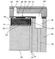
次に、本実施形態のインクジェット記録装置の記録ヘッド34を構成する液滴吐出ヘッドの一例について、図4及び図5を参照して説明する。なお、図4は、同ヘッドの液室長手方向に沿う断面説明図であり、図5は、同ヘッドの液室短手方向(ノズルの並び方向)の断面説明図である。
Next, an example of a droplet discharge head constituting the
当該液滴吐出ヘッドは、例えば、単結晶シリコン基板を異方性エッチングして形成した流路板101と、流路板101の下面に接合した例えばニッケル電鋳で形成した振動板102と、流路板101の上面に接合したノズル板103とを接合して積層して構成されている。また、該液滴吐出ヘッドは、これらによって液滴(インク滴)を吐出するノズル104が連通する流路であるノズル連通路105、液室106、そして液室106にインクを供給するための共通液室108に連通するインク供給口109等を形成している。
The droplet discharge head includes, for example, a
また、振動板102を変形させて液室106内のインクを加圧するための圧力発生手段(アクチュエータ手段)である電気機械変換素子としての2列(図4では1列のみ図示)の積層型圧電素子121と、圧電素子121を接合固定するベース基板122とを備えている。なお、圧電素子121の間には、支柱部123が設けられている。支柱部123は、圧電素子部材を分割加工することで圧電素子121と同時に形成した部分であるが、駆動電圧を印加しないので単なる支柱となる。
Also, two rows (only one row is shown in FIG. 4) of stacked piezoelectric elements as electromechanical conversion elements that are pressure generating means (actuator means) for deforming the
また、圧電素子121には、図示しない駆動回路(駆動IC)に接続するためのFPCケーブル124が接続されている。
In addition, an
そして、振動板102の周縁部をフレーム部材130に接合し、フレーム部材130は、圧電素子121及びベース基板122等で構成されるアクチュエータユニットを収納する貫通部131と、共通液室108となる凹部と、共通液室108に外部からインクを供給するためのインク供給穴132とを形成している。フレーム部材130は、例えばエポキシ系樹脂等の熱硬化性樹脂あるいはポリフェニレンサルファイトを射出成形することによって形成されている。
The peripheral portion of the
ここで、流路板101は、例えば結晶面方位(110)の単結晶シリコン基板を水酸化カリウム水溶液(KOH)等のアルカリ性エッチング液を用いて異方性エッチングすることで、ノズル連通路105、液室106となる凹部や穴部を形成したものであるが、単結晶シリコン基板に限られるものではなく、その他のステンレス基板や感光性樹脂等を用いることもできる。
Here, the
振動板102は、ニッケルの金属プレートから形成したもので、例えばエレクトロフォーミング法(電鋳法)で作製しているが、この他に、金属板や金属と樹脂板との接合部材等を用いることもできる。振動板102に圧電素子121及び支柱部123を接着剤で接合し、さらにフレーム部材130を接着剤接合している。
The
ノズル板103には、各液室106に対応して直径10〜30μmのノズル104が形成され、流路板101に接着剤接合している。ノズル板103は、金属部材からなるノズル形成部材の表面に所要の層を介して最表面に撥水層を形成したものである。
In the
圧電素子121は、圧電材料151と内部電極152とを交互に積層した積層型圧電素子(ここではPZT)である。圧電素子121の交互に異なる端面に引き出された各内部電極152には、個別電極153及び共通電極154が接続されている。なお、本実施形態では、圧電素子121の圧電方向としてd33方向の変位を用いて液室106内インクを加圧する構成としているが、圧電素子121の圧電方向としてd31方向の変位を用いて加圧液室106内インクを加圧する構成とすることも可能である。また、1つの基板122に1列の圧電素子121が設けられる構造とすることもできる。
The
このように構成した液滴吐出ヘッドにおいては、例えば圧電素子121に印加する電圧を基準電位から下げることによって圧電素子121が収縮し、振動板102が下降して液室106の容積が膨張することで、液室106内にインクが流入する。そして、その後に圧電素子121に印加する電圧を上げて圧電素子121を積層方向に伸長させ、振動板102をノズル104方向に変形させて液室106の容積/体積を収縮させることにより、液室106内の記録液が加圧され、ノズル104から記録液の滴が吐出(噴射)される。
In the droplet discharge head configured as described above, for example, by lowering the voltage applied to the
また、圧電素子121に印加する電圧を基準電位に戻すことによって振動板102が初期位置に復元し、液室106が膨張して負圧が発生するので、このとき、共通液室108から液室106内に記録液が充填される。そこで、ノズル104のメニスカス面の振動が減衰して安定した後、次の液滴吐出のための動作に移行する。
In addition, by returning the voltage applied to the
なお、このヘッドの駆動方法については上記の例(引き−押し打ち)に限るものではなく、駆動波形の与えた方によって引き打ちや押し打ち等を行うこともできる。 Note that the driving method of the head is not limited to the above example (drawing-pushing), and it is also possible to perform striking, pushing, or the like depending on the direction of the drive waveform.
次に、本実施形態のインクジェット記録装置の制御部の概要について、図6を参照して説明する。なお、同図は同制御部の全体ブロック説明図である。 Next, an outline of the control unit of the ink jet recording apparatus according to the present embodiment will be described with reference to FIG. This figure is an overall block diagram of the control unit.
制御部200は、記録装置全体の制御を司るCPU201と、CPU201が実行するプログラムやその他の固定データを格納するROM202と、画像データ等を一時格納するRAM203と、記録装置の電源が遮断されている間もデータを保持するための不揮発性メモリ(NVRAM)204と、画像データに対する各種信号処理、並び替え等を行う画像処理やその他装置全体を制御するための入出力信号を処理するASIC205とを備えている。
The
また、制御部200は、パーソナルコンピュータ等の画像処理装置(あるいはデータ処理装置)であるホスト側とのデータ、信号の送受を行うためのホストI/F206と、記録ヘッド34を駆動するための駆動波形を生成する駆動波形生成部207と、記録ヘッド34を駆動制御するヘッドドライバ208と、主走査モータ212を駆動するための主走査モータ駆動部211と、副走査モータ214を駆動するための副走査モータ駆動部213と、帯電ローラ56に対してACバイアス電圧を供給するACバイアス供給部215と、各種センサからの検知信号などを入力するためのI/O216等を備えている。
The
ここで、制御部200は、パーソナルコンピュータ等の画像処理装置、イメージスキャナ等の画像読取装置、デジタルカメラ等の撮像装置といったホスト側からの画像データを含む印刷データ(印字データ)等を、ケーブルあるいはネットを介してホストI/F206から受信する。
Here, the
そして、CPU201は、ホストI/F206に含まれる受信バッファ内の印刷データを読み出して解析し、ASIC205にて必要な画像処理、データの並び替え処理等を行ってヘッドドライバ208に画像データを転送する。なお、画像出力するためのドットパターンデータの生成は、例えばROM202にフォントデータを格納して行ってもよいし、ホスト側のプリンタドライバで画像データをビットマップデータに展開してこの装置に転送するようにしてもよい。
The
駆動波形生成部207は、駆動パルスのパターンデータをD/A変換するD/A変換器等で構成され、1の駆動パルス(駆動信号)又は複数の駆動パルス(駆動信号)で構成される駆動波形をヘッドドライバ208に対して出力する。
The drive
ヘッドドライバ208は、シリアルに入力される記録ヘッド34の1行分に相当する画像データ(ドットパターンデータ)に基づいて、駆動波形生成部207から与えられる駆動波形を構成する駆動パルスを選択的に記録ヘッド34の圧力発生手段(圧電素子121)に印加して記録ヘッド34を駆動する。
The
次に、本実施形態のインクジェット記録装置で使用するインク(記録液、以下「本インク」という)の一例について説明する。 Next, an example of ink (recording liquid, hereinafter referred to as “main ink”) used in the ink jet recording apparatus of the present embodiment will be described.
本インクは、以下の(1)ないし(10)で構成され、印字するための着色剤として、顔料を使用し、それを分解、分散させるための溶剤とを必須成分とする。さらに、添加剤として、湿潤剤、界面活性剤、エマルジョン、防腐剤、pH調整剤とを使用する。湿潤剤1と湿潤剤2とを混合するのは、各々湿潤剤の特徴を活かすためと、粘度調整が容易にできるためである。
(1) 顔料(自己分散性顔料)6wt%以上
(2) 湿潤剤1
(3) 湿潤剤2
(4) 溶性有機溶剤
(5) ニオンまたはノニオン系界面活性剤
(6) 炭素数8以上のポリオールまたはグリコールエーテル
(7) エマルジョン
(8) 防腐剤
(9) pH調整剤
(10) 純水
上記の各インク構成要素について、より具体的に説明する。
This ink is composed of the following (1) to (10), and a pigment is used as a colorant for printing, and an essential component is a solvent for decomposing and dispersing the pigment. Further, wetting agents, surfactants, emulsions, preservatives, pH adjusters are used as additives. The reason why the
(1) Pigment (self-dispersing pigment) 6 wt% or more (2)
(3)
(4) Soluble organic solvent (5) Nion or nonionic surfactant (6) Polyol or glycol ether having 8 or more carbon atoms (7) Emulsion (8) Preservative (9) pH adjuster (10) Pure water Each ink component will be described more specifically.
(1)の顔料に関しては、特にその種類を限定することなく、無機顔料、有機顔料を使用することができる。無機顔料としては、酸化チタン及び酸化鉄に加え、コンタクト法、ファーネス法、サーマル法等の公知の方法によって製造されたカーボンブラックを使用することができる。また、有機顔料としては、アゾ顔料(アゾレーキ、不溶性アゾ顔料、縮合アゾ顔料、キレートアゾ顔料等を含む)、多環式顔料(例えば、フタロシアニン顔料、ぺリレン顔料、ぺリノン顔料、アントラキノン顔料、キナクリドン顔料、ジオキサジン顔料、チオインジゴ顔料、イソインドリノン顔料、キノフラロン顔料等)、染料キレート(例えば、塩基性染料型キレート、酸性染料型キレート等)、ニトロ顔料、ニトロソ顔料、アニリンブラック等を使用できる。 Regarding the pigment of (1), inorganic pigments and organic pigments can be used without any particular limitation. As the inorganic pigment, in addition to titanium oxide and iron oxide, carbon black produced by a known method such as a contact method, a furnace method, or a thermal method can be used. Organic pigments include azo pigments (including azo lakes, insoluble azo pigments, condensed azo pigments, chelate azo pigments), polycyclic pigments (for example, phthalocyanine pigments, perylene pigments, perinone pigments, anthraquinone pigments, quinacridone pigments). , Dioxazine pigments, thioindigo pigments, isoindolinone pigments, quinofullerone pigments, etc.), dye chelates (for example, basic dye chelate, acidic dye chelate, etc.), nitro pigments, nitroso pigments, aniline black, and the like.
これらの顔料のうち、水と親和性の良いものが好ましく用いられる。顔料の粒径は、0.05μmから10μm以下が好ましく、さらに好ましくは1μm以下であり、最も好ましくは0.16μm以下である。インク中の着色剤としての顔料の添加量は、6〜20wt%程度が好ましく、より好ましくは8〜12wt%程度である。 Of these pigments, those having good affinity with water are preferably used. The particle diameter of the pigment is preferably 0.05 μm to 10 μm, more preferably 1 μm or less, and most preferably 0.16 μm or less. The amount of pigment added as a colorant in the ink is preferably about 6 to 20 wt%, more preferably about 8 to 12 wt%.
本インクにおいて好ましく用いられる顔料の具体例としては、以下のものが挙げられる。黒色用としては、ファーネスブラック、ランプブラック、アセチレンブラック、チャンネルブラック等のカーボンブラック(C.I.ピグメントブラック7)類、または銅、鉄(C.I.ピグメントブラック11)、酸化チタン等の金属類、アニリンブラック(C.I.ピグメントブラック1)等の有機顔料が挙げられる。 Specific examples of pigments preferably used in the ink include the following. For black, carbon black (CI Pigment Black 7) such as furnace black, lamp black, acetylene black, channel black, or metal such as copper, iron (CI Pigment Black 11), titanium oxide And organic pigments such as aniline black (CI Pigment Black 1).
また、カラー用としては、C.I.ピグメントイエロー1(ファストイエローG)、3、12(ジスアゾイエローAAA)、13、14、17、24、34、35、37、42(黄色酸化鉄)、53、55、81、83(ジスアゾイエローHR)、95、97、98、100、101、104、408、109、110、117、120、138、153、C.I.ピグメントオレンジ5、13、16、17、36、43、51、C.I.ピグメントレッド1、2、3、5、17、22(ブリリアントファーストスカレット)、23、31、38、48:2(パーマネントレッド2B(Ba))、48:2(パーマネントレッド2B(Ca))、48:3(パーマネントレッド2B(Sr))、48:4(パーマネントレッド2B(Mn))、49:1、52:2、53:1、57:1(ブリリアントカーミン6B)、60:1、63:1、63:2、64:1、81(ローダミン6Gレーキ)、83、88、101(べんがら)、104、105、106、108(カドミウムレッド)、112、114、122(キナクリドンマゼンタ)、123、146、149、166、168、170、172、177、178、179、185、190、193、209、219、C.I.ピグメントバイオレット1(ローダミンレーキ)、3、5:1、16、19、23、38、C.I.ピグメントブルー1、2、15(フタロシアニンブルーR)、15:1、15:2、15:3(フタロシアニンブルーE)、16、17:1、56、60、63、C.I.ピグメントグリーン1、4、7、8、10、17、18、36等がある。
For color, C.I. I. Pigment Yellow 1 (Fast Yellow G), 3, 12 (Disazo Yellow AAA), 13, 14, 17, 24, 34, 35, 37, 42 (Yellow Iron Oxide), 53, 55, 81, 83 (Disazo Yellow HR) ), 95, 97, 98, 100, 101, 104, 408, 109, 110, 117, 120, 138, 153, C.I. I.
その他、顔料(例えばカーボン)の表面を樹脂等で処理し、水中に分散可能としたグラフト顔料や、顔料(例えばカーボン)の表面にスルホン基やカルボキシル基等の官能基を付加し水中に分散可能とした加工顔料等が使用できる。また、顔料をマイクロカプセルに包含させ、該顔料を水中に分散可能なものとしたものであってもよい。 In addition, the surface of pigment (for example, carbon) can be dispersed in water by adding a functional group such as a sulfone group or a carboxyl group to the surface of the pigment (for example, carbon) that has been treated with resin to disperse in water. The processed pigment etc. which were made can be used. Further, the pigment may be included in the microcapsule so that the pigment can be dispersed in water.
本インクの好ましい態様によれば、ブラックインク用の顔料は、顔料を分散剤で水性媒体中に分散させて得られた顔料分散液としてインクに添加されるのが好ましい。好ましい分散剤としては、従来公知の顔料分散液を調整するのに用いられる公知の分散液を使用することができる。 According to a preferred embodiment of the present ink, the pigment for black ink is preferably added to the ink as a pigment dispersion obtained by dispersing the pigment in an aqueous medium with a dispersant. As a preferable dispersing agent, a known dispersion used for preparing a conventionally known pigment dispersion can be used.
また、分散液としては、例えば以下のものが挙げられる。ポリアクリル酸、ポリメタクリル酸、アクリル酸−アクリロニトリル共重合体、酢酸ビニル−アクリル酸エステル共重合体、アクリル酸−アクリル酸アルキルエステル共重合体、スチレン−アクリル酸共重合体、スチレン−メタクリル酸共重合体、スチレン−アクリル酸−アクリル酸アルキルエステル共重合体、スチレン−メタクリル酸−アクリル酸アルキルエステル共重合体、スチレン−α−メチルスチレン−アクリル酸共重合体、スチレン−α−メチルスチレン−アクリル酸共重合体−アクリル酸アルキルエステル共重合体、スチレン−マレイン酸共重合体、ビニルナフタレン−マレイン酸共重合体、酢酸ビニル−エチレン共重合体、酢酸ビニル−脂肪酸ビニルエチレン共重合体、酢酸ビニル−マレイン酸エステル共重合体、酢酸ビニル−クロトン酸共重合体、酢酸ビニル−アクリル酸共重合体等が挙げられる。 Moreover, as a dispersion liquid, the following are mentioned, for example. Polyacrylic acid, polymethacrylic acid, acrylic acid-acrylonitrile copolymer, vinyl acetate-acrylic acid ester copolymer, acrylic acid-acrylic acid alkyl ester copolymer, styrene-acrylic acid copolymer, styrene-methacrylic acid copolymer Polymer, styrene-acrylic acid-alkyl acrylate ester copolymer, styrene-methacrylic acid-alkyl acrylate copolymer, styrene-α-methylstyrene-acrylic acid copolymer, styrene-α-methylstyrene-acrylic Acid copolymer-alkyl acrylate ester copolymer, styrene-maleic acid copolymer, vinyl naphthalene-maleic acid copolymer, vinyl acetate-ethylene copolymer, vinyl acetate-fatty acid vinyl ethylene copolymer, vinyl acetate -Maleate ester copolymer, vinyl acetate- Examples include crotonic acid copolymers and vinyl acetate-acrylic acid copolymers.
本インクの好ましい態様によれば、これらの共重合体は重量平均分子量が3,000〜50,000であるのが好ましく、より好ましくは5,000〜30,000、最も好ましくは7,000〜15、000である。分散剤の添加量は、顔料を安定に分散させ、本発明の他の効果を失わせない範囲で適宣添加されてよい。分散剤としては1:0.06〜1:3の範囲が好ましく、より好ましくは1:0.125〜1:3の範囲である。 According to a preferred embodiment of the ink, these copolymers preferably have a weight average molecular weight of 3,000 to 50,000, more preferably 5,000 to 30,000, and most preferably 7,000 to 7,000. 15,000. The addition amount of the dispersant may be appropriately added within a range in which the pigment is stably dispersed and the other effects of the present invention are not lost. The dispersant is preferably in the range of 1: 0.06 to 1: 3, more preferably in the range of 1: 0.125 to 1: 3.
着色剤に使用する顔料は、記録用インク全重量に対して6wt%〜20wt%含有し、0.05μm〜0.16μm以下の粒子径の粒子であり、分散剤により水中に分散されていて、分散剤が、分子量5,000〜100,000の高分子分散剤である。水溶性有機溶剤が少なくとも1種類にピロリドン誘導体、特に、2−ピロリドンを使用すると画像品質が向上する。 The pigment used for the colorant is a particle having a particle size of 0.05 μm to 0.16 μm or less, containing 6 wt% to 20 wt% with respect to the total weight of the recording ink, and is dispersed in water by a dispersant. The dispersant is a polymer dispersant having a molecular weight of 5,000 to 100,000. When at least one water-soluble organic solvent is a pyrrolidone derivative, particularly 2-pyrrolidone, the image quality is improved.
(2)〜(4)の湿潤剤1、2と、水溶性有機溶剤に関しては、本インクの場合、インク中に水を液媒体として使用するものであるが、インクを所望の物性にし、インクの乾燥を防止するために、また、溶解安定性を向上するため等の目的で、例えば下記の水溶性有機溶剤が使用される。これら水溶性有機溶剤は複数混合して使用してもよい。
Regarding the
湿潤剤と水溶性有機溶剤の具体例としては、例えば以下のものが挙げられる。エチレングリコール、ジエチレングリコール、トリエチレングリコール、プロピレングリコール、ジプロピレングリコール、トリプロピレングリコール、テトラエチレングリコール、ヘキシレングリコール、ポリエチレングリコール、ポリプロピレングリコール、1,5−ペンタンジオール、1,6−ヘキサンジオール、グリセロール、1,2,6−ヘキサントリオール、1,2,4−ブタントリオール、1,2,3−ブタントリオール、ペトリオール等の多価アルコール類;エチレングリコールモノエチルエーテル、エチレングリコールモノブチルエーテル、ジエチレングリコールモノメチルエーテル、ジエチレングリコールモノエチルエーテル、ジエチレングリコールモノブチルエーテル、テトラエチレングリコールモノメチルエーテル、プロピレングリコールモノエチルエーテル等の多価アルコールアルキルエーテル類;エチレングリコールモノフェニルエーテル、エチレングリコールモノベンジルエーテル等の多価アルコールアリールエーテル類;2−ピロリドン、N−メチル−2−ピロリドン、N−ヒドロキシエチル−2−ピロリドン、1,3−ジメチルイミイダゾリジノン、ε−カプロラクタム、γ−ブチロラクトン等の含窒素複素環化合物;ホルムアミド、N−メチルホルムアミド、N,N−ジメチルホルムアミド等のアミド類;モノエタノールアミン、ジエタノールアミン、トリエタノールアミン、モノエチルアミン、ジエチルアミン、トリエチルアミン等のアミン類;ジメチルスルホキシド、スルホラン、チオジエタノール等の含硫黄化合物類;プロピレンカーボネート、炭酸エチレン等である。 Specific examples of the wetting agent and the water-soluble organic solvent include the following. Ethylene glycol, diethylene glycol, triethylene glycol, propylene glycol, dipropylene glycol, tripropylene glycol, tetraethylene glycol, hexylene glycol, polyethylene glycol, polypropylene glycol, 1,5-pentanediol, 1,6-hexanediol, glycerol, Polyhydric alcohols such as 1,2,6-hexanetriol, 1,2,4-butanetriol, 1,2,3-butanetriol, petriol; ethylene glycol monoethyl ether, ethylene glycol monobutyl ether, diethylene glycol monomethyl ether , Diethylene glycol monoethyl ether, diethylene glycol monobutyl ether, tetraethylene glycol monomethyl ether Polyhydric alcohol alkyl ethers such as propylene glycol monoethyl ether; Polyhydric alcohol aryl ethers such as ethylene glycol monophenyl ether and ethylene glycol monobenzyl ether; 2-pyrrolidone, N-methyl-2-pyrrolidone, N-hydroxyethyl Nitrogen-containing heterocyclic compounds such as 2-pyrrolidone, 1,3-dimethylimidazolidinone, ε-caprolactam, γ-butyrolactone; amides such as formamide, N-methylformamide, N, N-dimethylformamide; monoethanol Amines such as amine, diethanolamine, triethanolamine, monoethylamine, diethylamine and triethylamine; sulfur-containing compounds such as dimethyl sulfoxide, sulfolane and thiodiethanol; propylene carbonate Over bets is ethylene carbonate.
これら有機溶媒の中でも、特にジエチレングリコール、チオジエタノール、ポリエチレングリコール200〜600、トリエチレングリコール、グリセロール、1,2,6−ヘキサントリオール、1,2,4−ブタントリオール、ペトリオール、1,5−ペンタンジオール、2−ピロリドン、N−メチル−2−ピロリドンが好ましい。これらは、溶解性と水分蒸発による噴射特性不良の防止に対して優れた効果が得られる。
Among these organic solvents, diethylene glycol, thiodiethanol,
その他の湿潤剤としては、糖を含有してなるのが好ましい。糖類の例としては、単糖類、二糖類、オリゴ糖類(三糖類および四糖類を含む)及び多糖類が挙げられ、好ましくはグルコース、マンノース、フルクトース、リボース、キシロース、アラビノース、ガラクトース、マルトース、セロビオース、ラクトース、スクロース、トレハロース、マルトトリオース等が挙げられる。ここで、多糖類とは広義の糖を意味し、α−シクロデキストリン、セルロース等自然界に広く存在する物質を含む意味に用いることとする。 The other wetting agent preferably contains sugar. Examples of saccharides include monosaccharides, disaccharides, oligosaccharides (including trisaccharides and tetrasaccharides) and polysaccharides, preferably glucose, mannose, fructose, ribose, xylose, arabinose, galactose, maltose, cellobiose, Examples include lactose, sucrose, trehalose, maltotriose and the like. Here, the polysaccharide means a saccharide in a broad sense and is used to include a substance that exists widely in nature, such as α-cyclodextrin and cellulose.
また、これらの糖類の誘導体としては、前述した糖類の還元糖(例えば、糖アルコール(一般式HOCH2(CHOH)nCH2OH(ここでn=2〜5の整数を表す)で表される)、酸化糖(例えば、アルドン酸、ウロン酸等)、アミノ酸、チオ酸等が挙げられる。特に、糖アルコールが好ましく、具体例としてはマルチトール、ソルビット等が挙げられる。これら糖類の含有量は、インク組成物の0.1〜40wt%、好ましくは0.5〜30wt%の範囲が適当である。 Moreover, as derivatives of these saccharides, reducing sugars of the saccharides described above (for example, sugar alcohol (represented by the general formula HOCH 2 (CHOH) nCH 2 OH (where n = 2 to 5 represents an integer)) , Oxidized sugars (for example, aldonic acid, uronic acid, etc.), amino acids, thioic acids, etc. In particular, sugar alcohols are preferred, and specific examples include maltitol, sorbit, etc. The range of 0.1 to 40 wt%, preferably 0.5 to 30 wt% of the ink composition is appropriate.
(5)の界面活性剤に関しても、特に限定はされないが、アニオン性界面活性剤としては、例えば、ポリオキシエチレンアルキルエーテル酢酸塩、ドデシルベンゼンスルホン酸塩、ラウリル酸塩、ポリオキシエチレンアルキルエーテルサルフェートの塩等が挙げられる。非イオン性界面活性剤としては、例えば、ポリオキシエチレンアルキルエーテル、ポリオキシエチレンアルキルエステル、ポリオキシエチレンソルビタン脂肪酸エステル、ポリオキシエチレンアルキルフェニルエーテル、ポリオキシエチレンアルキルアミン、ポリオキシエチレンアルキルアミド等が挙げられる。前記界面活性剤は、単独あるいは二種以上を混合して用いることができる。 The surfactant of (5) is not particularly limited, but examples of the anionic surfactant include polyoxyethylene alkyl ether acetate, dodecylbenzene sulfonate, laurate, polyoxyethylene alkyl ether sulfate. And the like. Nonionic surfactants include, for example, polyoxyethylene alkyl ether, polyoxyethylene alkyl ester, polyoxyethylene sorbitan fatty acid ester, polyoxyethylene alkyl phenyl ether, polyoxyethylene alkylamine, polyoxyethylene alkylamide, and the like. Can be mentioned. The surfactants can be used alone or in admixture of two or more.
本インクにおける表面張力は、紙への浸透性を示す指標であり、特に表面形成されて1秒以下の短い時間での動的表面張力を示し、飽和時間で測定される静的表面張力とは異なる。測定法としては、従来公知の方法(例えば特開昭63−31237号公報等に記載)で、1秒以下の動的な表面張力を測定できる方法であればいずれも使用できるが、ここでは、Wilhelmy式の吊り板式表面張力計を用いて測定した。表面張力の値は、40mJ/m2以下が好ましく、より好ましくは35mJ/m2以下とすると優れた定着性と乾燥性が得られる。
The surface tension in this ink is an index indicating the permeability to paper. In particular, the surface tension indicates the dynamic surface tension in a short time of 1 second or less after the surface is formed, and the static surface tension measured by the saturation time is Different. As a measuring method, any conventionally known method (for example, described in JP-A-63-131237) can be used as long as it can measure a dynamic surface tension of 1 second or less. It measured using the Wilhelmy type suspension plate type surface tension meter. When the surface tension value is preferably 40 mJ /
(6)の炭素数8以上のポリオールあるいはグリコールエーテルに関しては、25℃の水中において、0.1〜4.5wt%未満の間の溶解度を有する部分的に、水溶性のポリオール、グリコールエーテルの少なくともいずれかを、記録用インク全重量に対して0.1〜10.0wt%添加することによって、該インクの熱素子への濡れ性が改良され、少量の添加量でも吐出安定性及び周波数安定性が得られることが分かった。
(a)2−エチル−1,3−ヘキサンジオール 溶解度:4.2%(20℃)
(b)2,2,4−トリメチル−1,3−ペンタンジオール 溶解度:2.0%(25℃)
25℃の水中において0.1〜4.5wt%未満の間の溶解度を有する浸透剤は、溶解度が低い代わりに浸透性が非常に高いという長所がある。したがって、25℃の水中において0.1〜4.5wt%未満の間の溶解度を有する浸透剤と他の溶剤との組合せや他の界面活性剤との組合せで非常に高浸透性のあるインクを作製することが可能となる。
Regarding the polyol or glycol ether having 8 or more carbon atoms of (6), at least a water-soluble polyol or glycol ether having a solubility of less than 0.1 to 4.5 wt% in water at 25 ° C. By adding either 0.1 to 10.0 wt% of the total amount of the recording ink, the wettability of the ink to the thermal element is improved, and even with a small addition amount, ejection stability and frequency stability are improved. Was found to be obtained.
(A) 2-ethyl-1,3-hexanediol Solubility: 4.2% (20 ° C.)
(B) 2,2,4-trimethyl-1,3-pentanediol Solubility: 2.0% (25 ° C.)
A penetrant having a solubility of less than 0.1-4.5 wt% in water at 25 ° C. has the advantage of very high permeability instead of low solubility. Therefore, an ink having a very high permeability by combining a penetrant having a solubility of less than 0.1 to 4.5 wt% in water at 25 ° C. with another solvent or another surfactant. It can be produced.
(7)本インクには樹脂エマルジョンが添加されている方が好ましい。樹脂エマルジョンとは、連続相が水であり、分散相が次のような樹脂成分であるエマルジョンを意味する。分散相の樹脂成分としては、アクリル系樹脂、酢酸ビニル系樹脂、スチレン−ブタジエン系樹脂、塩化ビニル系樹脂、アクリル−スチレン系樹脂、ブタジエン系樹脂、スチレン系樹脂等が挙げられる。 (7) It is preferable that a resin emulsion is added to the ink. The resin emulsion means an emulsion in which the continuous phase is water and the dispersed phase is the following resin component. Examples of the resin component of the dispersed phase include acrylic resins, vinyl acetate resins, styrene-butadiene resins, vinyl chloride resins, acrylic-styrene resins, butadiene resins, and styrene resins.
なお、本インクの好ましい態様によれば、この樹脂は親水性部分と疎水性部分とを併せ持つ重合体であるのが好ましい。また、これらの樹脂成分の粒子径は、エマルジョンを形成する限り特に限定されないが、150nm程度以下が好ましく、より好ましくは5〜100nm程度である。 According to a preferred embodiment of the present ink, this resin is preferably a polymer having both a hydrophilic part and a hydrophobic part. The particle size of these resin components is not particularly limited as long as an emulsion is formed, but is preferably about 150 nm or less, more preferably about 5 to 100 nm.
これらの樹脂エマルジョンは、樹脂粒子を、場合によって界面活性剤とともに水に混合することによって得ることができる。例えば、アクリル系樹脂あるいはスチレン−アクリル系樹脂のエマルジョンは、(メタ)アクリル酸エステルまたはスチレンと、(メタ)アクリル酸エステルと、場合により(メタ)アクリル酸エステルと、界面活性剤とを水に混合することによって得ることができる。樹脂成分と界面活性剤との混合の割合は、通常10:1〜5:1程度とするのが好ましい。界面活性剤の使用量が前記範囲に満たない場合、エマルジョンとなりにくく、また前記範囲を超える場合、インクの耐水性が低下する、あるいは浸透性が悪化する傾向があるので好ましくない。 These resin emulsions can be obtained by mixing resin particles in water, optionally with a surfactant. For example, an acrylic resin or styrene-acrylic resin emulsion can be obtained by adding (meth) acrylic acid ester or styrene, (meth) acrylic acid ester, and optionally (meth) acrylic acid ester, and a surfactant in water. It can be obtained by mixing. The mixing ratio of the resin component and the surfactant is usually preferably about 10: 1 to 5: 1. When the amount of the surfactant used is less than the above range, it is difficult to form an emulsion, and when it exceeds the above range, the water resistance of the ink tends to be lowered or the penetrability tends to deteriorate.
前記エマルジョンの分散相成分としての樹脂と水との割合は、樹脂100重量部に対して水60〜400重量部、好ましくは100〜200の範囲が適当である。市販の樹脂エマルジョンとしては、マイクロジェルE−1002、E−5002(スチレン−アクリル系樹脂エマルジョン、日本ペイント株式会社製)、ボンコート4001(アクリル系樹脂エマルジョン、大日本インキ化学工業株式会社製)、ボンコート5454(スチレン−アクリル系樹脂エマルジョン、大日本インキ化学工業株式会社製)、SAE−1014(スチレン−アクリル系樹脂エマルジョン、日本ゼオン株式会社製)、サイビノールSK−200(アクリル系樹脂エマルジョン、サイデン化学株式会社製)、等が挙げられる。本インクは、樹脂エマルジョンを、その樹脂成分がインクの0.1〜40wt%となるよう含有するのが好ましく、より好ましくは1〜25wt%の範囲である。 The ratio of the resin as the dispersed phase component of the emulsion and water is 60 to 400 parts by weight, preferably 100 to 200 parts by weight with respect to 100 parts by weight of the resin. Commercially available resin emulsions include Microgel E-1002, E-5002 (styrene-acrylic resin emulsion, manufactured by Nippon Paint Co., Ltd.), Boncoat 4001 (acrylic resin emulsion, manufactured by Dainippon Ink & Chemicals, Inc.), Boncoat 5454 (styrene-acrylic resin emulsion, manufactured by Dainippon Ink & Chemicals, Inc.), SAE-1014 (styrene-acrylic resin emulsion, manufactured by Nippon Zeon Co., Ltd.), Cybinol SK-200 (acrylic resin emulsion, Seiden Chemical Co., Ltd.) Etc.). The ink preferably contains a resin emulsion such that the resin component is 0.1 to 40 wt% of the ink, more preferably 1 to 25 wt%.
このように、樹脂エマルジョンは、増粘・凝集する性質を持ち、着色成分の浸透を抑制し、さらに記録材への定着を促進する効果を有する。また、樹脂エマルジョンの種類によっては記録材上で皮膜を形成し、印刷物の耐擦性をも向上させる効果を有する。 As described above, the resin emulsion has the property of thickening and aggregating, has the effect of suppressing the penetration of the coloring component, and further promoting the fixing to the recording material. Further, depending on the type of resin emulsion, a film is formed on the recording material, and the printed material has an effect of improving the abrasion resistance.
(8)〜(10)本インクには上記着色剤、溶媒、界面活性剤の他に従来から知られている添加剤を加えることができる。例えば、防腐防黴剤としては、デヒドロ酢酸ナトリウム、ソルビン酸ナトリウム、2−ピリジンチオール−1−オキサイドナトリウム、安息香酸ナトリウム、ペンタクロロフェノールナトリウム等が使用できる。 (8)-(10) In addition to the colorant, solvent, and surfactant, conventionally known additives can be added to the ink. For example, as an antiseptic / antifungal agent, sodium dehydroacetate, sodium sorbate, sodium 2-pyridinethiol-1-oxide, sodium benzoate, sodium pentachlorophenol and the like can be used.
pH調整剤としては、調合されるインクに悪影響をおよぼさずにpHを7以上に調整できるものであれば、任意の物質を使用することができる。その例として、ジエタノールアミン、トリエタノールアミン等のアミン、水酸化リチウム、水酸化ナトリウム、水酸化カリウム等のアルカリ金属元素の水酸化物、水酸化アンモニウム、第4級アンモニウム水酸化物、第4級ホスホニウム水酸化物、炭酸リチウム、炭酸ナトリウム、炭酸カリウム等のアルカリ金属の炭酸塩等が挙げられる。 As the pH adjuster, any substance can be used as long as the pH can be adjusted to 7 or more without adversely affecting the ink to be prepared. Examples thereof include amines such as diethanolamine and triethanolamine, hydroxides of alkali metal elements such as lithium hydroxide, sodium hydroxide and potassium hydroxide, ammonium hydroxide, quaternary ammonium hydroxide, and quaternary phosphonium. Examples thereof include carbonates of alkali metals such as hydroxide, lithium carbonate, sodium carbonate, and potassium carbonate.
なお、キレート試薬としては、例えば、エチレンジアミン四酢酸ナトリウム、ニトリロ三酢酸ナトリウム、ヒドロキシエチルエチレンジアミン三酢酸ナトリウム、ジエチレントリアミン五酢酸ナトリウム、ウラミル二酢酸ナトリウム等がある。 Examples of the chelating reagent include sodium ethylenediaminetetraacetate, sodium nitrilotriacetate, sodium hydroxyethylethylenediaminetriacetate, sodium diethylenetriaminepentaacetate, sodium uramil diacetate, and the like.
また、防錆剤としては、例えば、酸性亜硫酸塩、チオ硫酸ナトリウム、チオジグリコール酸アンモン、ジイソプロピルアンモニウムニトライト、四硝酸ペンタエリスリトール、ジシクロヘキシルアンモニウムニトライト等がある。 Examples of the rust inhibitor include acidic sulfite, sodium thiosulfate, ammonium thiodiglycolate, diisopropylammonium nitrite, pentaerythritol tetranitrate, and dicyclohexylammonium nitrite.
次に、本実施形態のインクジェット記録装置において生成される駆動信号について、図7から12を参照して説明する。 Next, drive signals generated in the ink jet recording apparatus of the present embodiment will be described with reference to FIGS.
本駆動信号は、1印刷周期内に複数あるいは単数の駆動パルスを有し、印字信号に応じて、異なる組合せの複数の駆動パルスあるいは単数の駆動パルスが選択される。図7は、印字信号と駆動信号の関係の例を示した図である。 This drive signal has a plurality or a single drive pulse in one printing cycle, and a plurality of drive pulses or a single drive pulse of different combinations are selected according to the print signal. FIG. 7 is a diagram illustrating an example of the relationship between the print signal and the drive signal.
波形としては、主に小滴波形、中滴波形、大滴波形の3種類があり、P1〜P8の8つの駆動パルスの組合せにより、印字信号に応じて駆動信号として生成される。例えば、印字信号Ps1が受信された場合は、大滴波形として、P2〜P8の組合せの駆動パルスが選択され、ヘッドに入力される。また、印字信号Ps2の場合は、中滴波形として、P4〜P6の組合せの駆動パルスが選択され、印字信号Ps3の場合は、小滴波形として、P1の駆動パルスが選択され、ヘッドに入力される。そして、上記3種類の波形に加えて微駆動波形があり、印字信号Ps4が受信された場合にPs2の駆動パルス(微駆動パルス)が選択され、ヘッドに入力される。 There are mainly three types of waveforms, a small droplet waveform, a medium droplet waveform, and a large droplet waveform, and are generated as a drive signal according to a print signal by a combination of eight drive pulses P1 to P8. For example, when the print signal Ps1 is received, a driving pulse having a combination of P2 to P8 is selected as a large droplet waveform and input to the head. In the case of the print signal Ps2, the combination drive pulse P4 to P6 is selected as the medium droplet waveform, and in the case of the print signal Ps3, the drive pulse P1 is selected as the small droplet waveform and input to the head. The In addition to the above three types of waveforms, there is a fine drive waveform. When the print signal Ps4 is received, the drive pulse (fine drive pulse) of Ps2 is selected and input to the head.
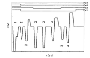
図8は、大滴波形として選択された駆動信号図である。同図では、微駆動パルスP2を含む7つの駆動パルスから構成されており、中滴波形としての駆動パルスP4〜P6を含んでいる。微駆動パルスはインク滴を吐出させずにメニスカスを振動させる駆動パルスであるため、駆動パルスP3〜P8のそれぞれによって吐出されたインク滴が飛翔中に合体し大滴となる。つまり、P3によって第1のインク滴が吐出され、P4、P5、P6によって第2、第3、第4のインク滴が吐出され、P7、P8により第5、第6のインク滴が吐出され、それらのインク滴が飛翔中に合体し、大径のインク滴となって記録紙に着弾する。 FIG. 8 is a drive signal diagram selected as a large droplet waveform. In the figure, it is composed of seven drive pulses including a fine drive pulse P2, and includes drive pulses P4 to P6 as medium droplet waveforms. Since the fine drive pulse is a drive pulse that vibrates the meniscus without ejecting ink droplets, the ink droplets ejected by each of the drive pulses P3 to P8 are combined into a large droplet during flight. That is, the first ink droplet is ejected by P3, the second, third, and fourth ink droplets are ejected by P4, P5, and P6, and the fifth and sixth ink droplets are ejected by P7 and P8. These ink droplets coalesce during the flight and become large-diameter ink droplets that land on the recording paper.
ここで、これら複数の駆動パルスのうち最終の駆動パルスP8については、駆動パルスP4、P5等のような単純引き打ち波形ではなく、引き込み電圧を小さくしたパルスとしている。これは、駆動パルスP8も他の駆動パルスのように単純引き打ち波形にすると、インク滴速度が大きくなり過ぎてしまい、小滴のような1パルスから構成されインク滴速度が相対的に大きくなりにくい他の滴種の着弾位置からずれてしまうおそれがあるためである。このように、引き込み電圧を小さくすることでメニスカスの引き込みを小さくし、最後に吐出されるインク滴速度を抑えているわけだが、単に引き込み電圧を小さくするだけでは、必要なインク滴体積を吐出させることが困難となるため、立ち上げ電圧を必要なインク滴体積を吐出させるのに十分な大きさにする必要がある。 Here, the final drive pulse P8 among the plurality of drive pulses is not a simple beat waveform such as the drive pulses P4 and P5 but a pulse with a reduced pull-in voltage. This is because if the drive pulse P8 has a simple striking waveform like the other drive pulses, the ink droplet velocity becomes too large, and the ink droplet velocity is relatively large because it is composed of one pulse like a small droplet. This is because there is a risk of shifting from the landing position of another difficult drop type. In this way, by reducing the pull-in voltage, the meniscus pull-in is reduced and the speed of the ink droplet ejected at the end is suppressed. However, by simply reducing the pull-in voltage, the necessary ink droplet volume is ejected. Therefore, it is necessary to make the start-up voltage large enough to eject the necessary ink droplet volume.
なお、駆動パルスP3及びP6においても、インク滴速度の調整やインク滴体積の蓄積といった目的で、引き込み電圧を小さくし立ち上げ電圧を維持するようにしている。 In the drive pulses P3 and P6, the pull-in voltage is reduced and the rising voltage is maintained for the purpose of adjusting the ink droplet speed and accumulating the ink droplet volume.
図9は、中滴波形として選択された駆動信号図である。同図は、P4、P5、P6といった3つの駆動パルスから構成されている。まず、駆動パルスP4にて1滴目、続いて駆動パルスP5にて2滴目、そして駆動パルスP6にて3滴目が吐出され、飛翔中に合体し中径のインク滴となって記録紙に着弾する。圧力室の固有振動周期をTcとすると、駆動パルスP4とP5の吐出タイミングの間隔は2Tc±0.5μsが望ましい。 FIG. 9 is a drive signal diagram selected as the medium droplet waveform. The figure is composed of three drive pulses P4, P5 and P6. First, the first droplet is ejected by the driving pulse P4, then the second droplet is ejected by the driving pulse P5, and the third droplet is ejected by the driving pulse P6. To land on. Assuming that the natural vibration period of the pressure chamber is Tc, the interval between the ejection timings of the drive pulses P4 and P5 is desirably 2Tc ± 0.5 μs.
最終の駆動パルスが単純引き打ち波形ではなく、引き込み電圧の小さいものとしているのは大滴波形の場合と同様である。すなわち、駆動パルスP4及びP5が単純引き打ち波形で構成されているが、駆動パルスP6を同様の単純引き打ち波形にするとインク滴速度が大きくなりすぎてしまい、インク滴速度が相対的に大きくなりにくい他の滴種の着弾位置からずれるおそれがあるため、駆動パルスP6は、引き込み電圧を小さくすることでメニスカスの引き込みを小さくし、3滴目のインク滴速度を抑えている。ただし、必要なインク滴体積をかせぐために立ち上げ電圧は小さくしない。 The final drive pulse is not a simple beat waveform, but has a small pull-in voltage, as in the case of a large drop waveform. In other words, the drive pulses P4 and P5 have a simple strike waveform. However, if the drive pulse P6 has the same simple strike waveform, the ink droplet velocity becomes too large, and the ink droplet velocity becomes relatively large. Since there is a possibility that it is difficult to deviate from the landing position of another difficult drop type, the driving pulse P6 reduces the pulling-in voltage to reduce the pulling-in of the meniscus and suppresses the ink drop speed of the third drop. However, the startup voltage is not reduced in order to increase the necessary ink droplet volume.
図10は、小滴波形として選択された駆動信号図である。ここでは、駆動パルスP1にて小滴としてインク滴が吐出されるわけだが、インク滴速度を抑えるのではなく速度を大きくするために、引き込み及び立ち上げの電圧を他の駆動パルスより大きく設定している。1パルスから構成されるインク滴は、インク滴速度が相対的に大きくなりにくく、他の滴種の着弾位置と揃わないおそれがあるためである。 FIG. 10 is a drive signal diagram selected as the droplet waveform. Here, the ink droplets are ejected as small droplets by the drive pulse P1, but in order to increase the speed rather than suppressing the ink droplet speed, the pull-in and rise voltages are set larger than those of the other drive pulses. ing. This is because an ink droplet composed of one pulse is less likely to have a relatively high ink droplet velocity and may not align with the landing positions of other droplet types.
図11は、微駆動波形として選択された駆動信号図である。微駆動波形とは、メニスカスの乾燥を防ぐため、インク滴を吐出させずにメニスカスを振動させるものである。微駆動波形は、主に非印字領域においてヘッドに入力される。 FIG. 11 is a drive signal diagram selected as the fine drive waveform. The fine driving waveform is to vibrate the meniscus without ejecting ink droplets in order to prevent the meniscus from drying. The fine driving waveform is input to the head mainly in the non-printing area.
なお、前述した大滴波形の中に微駆動パルスP2が含まれていたが、これは、大滴を構成する駆動パルスの1つとして微駆動パルスを利用しており、駆動周期の短縮化(高速化)を達成している。さらに、微駆動パルスP2と駆動パルスP3の吐出タイミングの間隔をTc±0.5μsに設定することにより、駆動パルスP3にて吐出するインク滴の体積を効率的に蓄積することが可能となる。 Note that the fine driving pulse P2 is included in the large droplet waveform described above, but this uses the fine driving pulse as one of the driving pulses constituting the large droplet, and shortens the driving cycle ( Speed). Furthermore, by setting the interval between the ejection timings of the fine driving pulse P2 and the driving pulse P3 to Tc ± 0.5 μs, it is possible to efficiently accumulate the volume of ink droplets ejected by the driving pulse P3.
図12は、インク粘度が5mPa・s、10mPa・s及び20mPa・sの場合の駆動信号図である。インク粘度が小さいときは駆動パルスの電圧を小さく、インク粘度が大きいときは駆動パルスの電圧を大きくすることにより、インク粘度(温度)に影響されずにインク滴の速度及び体積を一定に保った状態で吐出させることができる。また、駆動パルスP2は、インク粘度にあわせて波高値を選択することにより、インク滴を吐出させることなくメニスカスを振動させることができる。 FIG. 12 is a drive signal diagram when the ink viscosity is 5 mPa · s, 10 mPa · s, and 20 mPa · s. When the ink viscosity is low, the drive pulse voltage is reduced, and when the ink viscosity is high, the drive pulse voltage is increased to keep the ink droplet velocity and volume constant regardless of the ink viscosity (temperature). Can be discharged in a state. Further, the driving pulse P2 can vibrate the meniscus without ejecting ink droplets by selecting a peak value according to the ink viscosity.
上記の実施形態によれば、複数のインク滴から構成される大滴や中滴と、1滴から構成される小滴の紙面上での着弾位置をそろえることができる。 According to the above embodiment, it is possible to align the landing positions on the paper surface of a large droplet or medium droplet composed of a plurality of ink droplets and a small droplet composed of one droplet.
また、上記の実施形態によれば、1印刷周期内において印字信号に応じて、大滴や中滴等、異なる組合せの複数の駆動パルスを選択することができるため、駆動周期の短縮化、すなわち高速化が可能である。 Further, according to the above-described embodiment, a plurality of driving pulses of different combinations such as large droplets and medium droplets can be selected in accordance with the print signal within one printing cycle, so that the driving cycle is shortened, that is, Speeding up is possible.
また、上記の実施形態によれば、非印字領域においては、インク滴を吐出させずにメニスカスを振動させるだけの微駆動パルスを備えているため、メニスカスの乾燥によるノズルの目詰まりや吐出異常を防ぐことができる。 Further, according to the above embodiment, in the non-printing region, the fine driving pulse that only vibrates the meniscus without ejecting ink droplets is provided, so that nozzle clogging or ejection abnormality due to meniscus drying is prevented. Can be prevented.
また、上記の実施形態によれば、微駆動パルスは、メニスカスの乾燥を防ぐためだけでなく、大滴の構成パルスとしても利用されるため、大滴の滴体積を効率的に蓄積することができる。 In addition, according to the above-described embodiment, the fine driving pulse is used not only to prevent meniscus drying but also as a constituent pulse of a large droplet, so that the droplet volume of the large droplet can be efficiently accumulated. it can.
また、上記の実施形態によれば、1印刷周期内において印字信号に応じて、大滴や中滴といったインク滴を吐出させる滴と、吐出させない微駆動パルスとを、組み合わせて複数の駆動パルスを選択することができるため、駆動周期の短縮化、すなわち高速化が可能である。 Further, according to the above-described embodiment, a plurality of drive pulses are generated by combining droplets that eject ink droplets such as large droplets and medium droplets and fine drive pulses that are not ejected in accordance with a print signal within one printing cycle. Since the selection can be made, the drive cycle can be shortened, that is, the speed can be increased.
また、上記の実施形態によれば、粘度が非常に大きいインクに対しても、また粘度が小さいインクに対しても、安定したインク滴吐出とノズルのメンテナンスが可能である。 Further, according to the above-described embodiment, stable ink droplet ejection and nozzle maintenance can be performed for ink having a very high viscosity and ink having a low viscosity.
なお、上述する実施形態は、本発明の好適な実施形態であり、上記実施形態のみに本発明の範囲を限定するものではなく、本発明の要旨を逸脱しない範囲において種々の変更を施した形態での実施が可能である。 The above-described embodiment is a preferred embodiment of the present invention, and the scope of the present invention is not limited to the above-described embodiment alone, and various modifications are made without departing from the gist of the present invention. Implementation is possible.
1 装置本体
2 給紙トレイ
3 排紙トレイ
4 カートリッジ装填部
5 操作/表示部
6 カートリッジカバー
10k,10c,10m,10y インクカートリッジ
11k,11c,11m,11y 残量表示部
12 電源ボタン
13 用紙送り/印刷再開ボタン
14 キャンセルボタン
33 キャリッジ
34 記録ヘッド
35 サブタンク
36 インク供給チューブ
81 維持回復機構
82 キャップ部材
83 ワイパーブレード
84,85 空吐出受け
101 流路板
102 振動板
103 ノズル板
104 ノズル
105 ノズル連通路
106 液室
108 共通液室
109 インク供給口
121 積層型圧電素子
122 ベース基板
124 支柱部
130 フレーム部材
131 貫通部
132 インク供給穴
151 圧電材料
152 内部電極
153 個別電極
154 共通電極
DESCRIPTION OF
Claims (10)
前記駆動信号発生手段により生成された駆動信号を供給することによって、前記圧力発生素子を作動させて前記ノズルからインク滴を吐出させるようにしたインクジェット記録装置において、
1印刷周期内に前記ノズルから吐出された複数のインク滴が飛翔中に合体するように設定された駆動パルスを有し、
前記駆動パルスの中の少なくともインク滴を吐出する最終の駆動パルスは、1印刷周期内で1つのインク滴をノズルより吐出する場合に、同一印刷周期内で前記最終の駆動パルスに先行して基準電位より単純引き打ち波形で印加される駆動パルスよりもメニスカスを引き込む引き込み電圧が小さく、かつ、前記基準電位よりも高い電位までのインク滴を吐出する立ち上げ電圧を有することを特徴とするインクジェット記録装置。 A plurality of nozzles for ejecting ink, a pressure chamber communicating with the nozzle, an ejection head having a pressure generating element for changing the volume of the pressure chamber, and a plurality of drive pulses for ejecting ink droplets within one printing cycle Drive signal generating means for generating a drive signal included in
In the ink jet recording apparatus, wherein the driving signal generated by the driving signal generating means is supplied to operate the pressure generating element to discharge ink droplets from the nozzle.
Having a drive pulse set so that a plurality of ink droplets ejected from the nozzle within one printing cycle merge during flight;
The final drive pulse for ejecting at least ink droplets in the drive pulse is a reference preceding the final drive pulse within the same printing cycle when one ink droplet is ejected from the nozzle within one printing cycle. Ink jet recording, characterized in that a pull-in voltage for pulling a meniscus is smaller than a drive pulse applied with a simple beat waveform than a potential and a rising voltage for discharging ink droplets to a potential higher than the reference potential apparatus.
Priority Applications (1)
| Application Number | Priority Date | Filing Date | Title |
|---|---|---|---|
| JP2005339154A JP4813157B2 (en) | 2005-10-25 | 2005-11-24 | Inkjet recording device |
Applications Claiming Priority (3)
| Application Number | Priority Date | Filing Date | Title |
|---|---|---|---|
| JP2005310333 | 2005-10-25 | ||
| JP2005310333 | 2005-10-25 | ||
| JP2005339154A JP4813157B2 (en) | 2005-10-25 | 2005-11-24 | Inkjet recording device |
Publications (3)
| Publication Number | Publication Date |
|---|---|
| JP2007144659A JP2007144659A (en) | 2007-06-14 |
| JP2007144659A5 JP2007144659A5 (en) | 2008-10-23 |
| JP4813157B2 true JP4813157B2 (en) | 2011-11-09 |
Family
ID=38206655
Family Applications (1)
| Application Number | Title | Priority Date | Filing Date |
|---|---|---|---|
| JP2005339154A Active JP4813157B2 (en) | 2005-10-25 | 2005-11-24 | Inkjet recording device |
Country Status (1)
| Country | Link |
|---|---|
| JP (1) | JP4813157B2 (en) |
Families Citing this family (6)
| Publication number | Priority date | Publication date | Assignee | Title |
|---|---|---|---|---|
| JP5987614B2 (en) * | 2012-09-28 | 2016-09-07 | ブラザー工業株式会社 | Liquid ejection device, control method of liquid ejection device, and control program |
| JP6260204B2 (en) | 2013-03-06 | 2018-01-17 | 株式会社リコー | INKJET RECORDING METHOD, INKJET RECORDING DEVICE, RECORDED PRODUCT MANUFACTURING METHOD |
| JP6311358B2 (en) * | 2013-05-02 | 2018-04-18 | 株式会社リコー | Control device, droplet discharge device, and method for controlling droplet discharge head |
| JP6696294B2 (en) * | 2016-05-10 | 2020-05-20 | 株式会社リコー | Drive waveform generation device, device for ejecting liquid |
| JP6820704B2 (en) * | 2016-09-15 | 2021-01-27 | 東芝テック株式会社 | Inkjet head drive device |
| JP7355117B2 (en) | 2019-12-25 | 2023-10-03 | コニカミノルタ株式会社 | Inkjet head driving method and inkjet recording device |
Family Cites Families (2)
| Publication number | Priority date | Publication date | Assignee | Title |
|---|---|---|---|---|
| JP4117162B2 (en) * | 2002-08-08 | 2008-07-16 | 松下電器産業株式会社 | Ink jet recording apparatus and ink droplet ejection speed adjusting method in the ink jet recording apparatus |
| JP2003127369A (en) * | 2001-10-29 | 2003-05-08 | Matsushita Electric Ind Co Ltd | Ink jet head and ink jet recorder |
-
2005
- 2005-11-24 JP JP2005339154A patent/JP4813157B2/en active Active
Also Published As
| Publication number | Publication date |
|---|---|
| JP2007144659A (en) | 2007-06-14 |
Similar Documents
| Publication | Publication Date | Title |
|---|---|---|
| JP5117026B2 (en) | Image forming apparatus | |
| JP6260204B2 (en) | INKJET RECORDING METHOD, INKJET RECORDING DEVICE, RECORDED PRODUCT MANUFACTURING METHOD | |
| EP3041682B1 (en) | Inkjet recording method and inkjet recording device | |
| JP2011116096A (en) | Image forming apparatus, image forming method, and program | |
| US9757942B2 (en) | Inkjet recording method and inkjet recording device | |
| JP2004017546A (en) | Imaging apparatus, image processor, printer driver and image processing method | |
| JP2009184190A (en) | Image forming method, program to perform the same, image processing device, image forming apparatus and image forming system | |
| JP2007125826A (en) | Image processing method, program, image processing apparatus, image forming apparatus and image forming system | |
| JP4813157B2 (en) | Inkjet recording device | |
| JP4566716B2 (en) | Image forming apparatus | |
| JP4353432B2 (en) | Image processing method, program, image processing apparatus, image forming apparatus, and image forming system | |
| JP2005170035A (en) | Maintenance and recovery unit and maintenance and recovery method using ink which rapidly increases viscosity (viscosity increase ratio (mpa s/%) exceeding 50) during moisture evaporation 30-45% and inkjet recording apparatus | |
| JP2004098310A (en) | Liquid drop ejecting head and manufacturing method therefor, ink cartridge and inkjet recorder | |
| JP2006142588A (en) | Imaging device | |
| JP2004160907A (en) | Inkjet recorder | |
| JP2004284084A (en) | Recovery method of liquid ejector and image forming apparatus | |
| JP2004114303A (en) | Ink jet recorder | |
| JP2016087801A (en) | Head driving device, ink jet recording device and method | |
| JP2017043082A (en) | Inkjet recording method and inkjet recording device | |
| JP2006056088A (en) | Image forming apparatus | |
| JP4111493B2 (en) | Droplet discharge head, method for manufacturing the same, ink cartridge, and ink jet recording apparatus | |
| JP2010120222A (en) | Image formation device, image forming method, and program | |
| JP2004082501A (en) | Liquid drop ejection head and its manufacturing process, ink cartridge and inkjet recorder | |
| JP2004098535A (en) | Liquid droplet jetting head, its manufacturing method, ink cartridge, and ink jet recording apparatus | |
| JP2003266668A (en) | Ink jet recorder |
Legal Events
| Date | Code | Title | Description |
|---|---|---|---|
| A521 | Written amendment |
Free format text: JAPANESE INTERMEDIATE CODE: A523 Effective date: 20080905 |
|
| A621 | Written request for application examination |
Free format text: JAPANESE INTERMEDIATE CODE: A621 Effective date: 20080905 |
|
| A131 | Notification of reasons for refusal |
Free format text: JAPANESE INTERMEDIATE CODE: A131 Effective date: 20101109 |
|
| A521 | Written amendment |
Free format text: JAPANESE INTERMEDIATE CODE: A523 Effective date: 20110107 |
|
| A02 | Decision of refusal |
Free format text: JAPANESE INTERMEDIATE CODE: A02 Effective date: 20110208 |
|
| A521 | Written amendment |
Free format text: JAPANESE INTERMEDIATE CODE: A523 Effective date: 20110506 |
|
| A911 | Transfer of reconsideration by examiner before appeal (zenchi) |
Free format text: JAPANESE INTERMEDIATE CODE: A911 Effective date: 20110516 |
|
| A131 | Notification of reasons for refusal |
Free format text: JAPANESE INTERMEDIATE CODE: A131 Effective date: 20110607 |
|
| A521 | Written amendment |
Free format text: JAPANESE INTERMEDIATE CODE: A523 Effective date: 20110715 |
|
| A521 | Written amendment |
Free format text: JAPANESE INTERMEDIATE CODE: A523 Effective date: 20110726 |
|
| TRDD | Decision of grant or rejection written | ||
| A01 | Written decision to grant a patent or to grant a registration (utility model) |
Free format text: JAPANESE INTERMEDIATE CODE: A01 Effective date: 20110823 |
|
| A01 | Written decision to grant a patent or to grant a registration (utility model) |
Free format text: JAPANESE INTERMEDIATE CODE: A01 |
|
| A61 | First payment of annual fees (during grant procedure) |
Free format text: JAPANESE INTERMEDIATE CODE: A61 Effective date: 20110824 |
|
| R150 | Certificate of patent or registration of utility model |
Ref document number: 4813157 Country of ref document: JP Free format text: JAPANESE INTERMEDIATE CODE: R150 Free format text: JAPANESE INTERMEDIATE CODE: R150 |
|
| FPAY | Renewal fee payment (event date is renewal date of database) |
Free format text: PAYMENT UNTIL: 20140902 Year of fee payment: 3 |