JP4812977B2 - ELECTRIC DEVICE, SUPPORTING AND MONITORING DEVICE FOR ELECTRIC SWITCHING DEVICE, AND ELECTRIC EQUIPMENT CONTAINING THEM - Google Patents
ELECTRIC DEVICE, SUPPORTING AND MONITORING DEVICE FOR ELECTRIC SWITCHING DEVICE, AND ELECTRIC EQUIPMENT CONTAINING THEM Download PDFInfo
- Publication number
- JP4812977B2 JP4812977B2 JP2001239005A JP2001239005A JP4812977B2 JP 4812977 B2 JP4812977 B2 JP 4812977B2 JP 2001239005 A JP2001239005 A JP 2001239005A JP 2001239005 A JP2001239005 A JP 2001239005A JP 4812977 B2 JP4812977 B2 JP 4812977B2
- Authority
- JP
- Japan
- Prior art keywords
- electromagnetic radiation
- electrical
- receiving means
- sensor
- electrical device
- Prior art date
- Legal status (The legal status is an assumption and is not a legal conclusion. Google has not performed a legal analysis and makes no representation as to the accuracy of the status listed.)
- Expired - Lifetime
Links
Images


Classifications
-
- H—ELECTRICITY
- H01—ELECTRIC ELEMENTS
- H01H—ELECTRIC SWITCHES; RELAYS; SELECTORS; EMERGENCY PROTECTIVE DEVICES
- H01H9/00—Details of switching devices, not covered by groups H01H1/00 - H01H7/00
- H01H9/16—Indicators for switching condition, e.g. "on" or "off"
- H01H9/168—Indicators for switching condition, e.g. "on" or "off" making use of an electromagnetic wave communication
-
- H—ELECTRICITY
- H01—ELECTRIC ELEMENTS
- H01H—ELECTRIC SWITCHES; RELAYS; SELECTORS; EMERGENCY PROTECTIVE DEVICES
- H01H9/00—Details of switching devices, not covered by groups H01H1/00 - H01H7/00
- H01H9/16—Indicators for switching condition, e.g. "on" or "off"
- H01H9/167—Circuits for remote indication
-
- H—ELECTRICITY
- H01—ELECTRIC ELEMENTS
- H01H—ELECTRIC SWITCHES; RELAYS; SELECTORS; EMERGENCY PROTECTIVE DEVICES
- H01H2300/00—Orthogonal indexing scheme relating to electric switches, relays, selectors or emergency protective devices covered by H01H
- H01H2300/03—Application domotique, e.g. for house automation, bus connected switches, sensors, loads or intelligent wiring
- H01H2300/032—Application domotique, e.g. for house automation, bus connected switches, sensors, loads or intelligent wiring using RFID technology in switching devices
-
- Y—GENERAL TAGGING OF NEW TECHNOLOGICAL DEVELOPMENTS; GENERAL TAGGING OF CROSS-SECTIONAL TECHNOLOGIES SPANNING OVER SEVERAL SECTIONS OF THE IPC; TECHNICAL SUBJECTS COVERED BY FORMER USPC CROSS-REFERENCE ART COLLECTIONS [XRACs] AND DIGESTS
- Y02—TECHNOLOGIES OR APPLICATIONS FOR MITIGATION OR ADAPTATION AGAINST CLIMATE CHANGE
- Y02B—CLIMATE CHANGE MITIGATION TECHNOLOGIES RELATED TO BUILDINGS, e.g. HOUSING, HOUSE APPLIANCES OR RELATED END-USER APPLICATIONS
- Y02B90/00—Enabling technologies or technologies with a potential or indirect contribution to GHG emissions mitigation
- Y02B90/20—Smart grids as enabling technology in buildings sector
-
- Y—GENERAL TAGGING OF NEW TECHNOLOGICAL DEVELOPMENTS; GENERAL TAGGING OF CROSS-SECTIONAL TECHNOLOGIES SPANNING OVER SEVERAL SECTIONS OF THE IPC; TECHNICAL SUBJECTS COVERED BY FORMER USPC CROSS-REFERENCE ART COLLECTIONS [XRACs] AND DIGESTS
- Y04—INFORMATION OR COMMUNICATION TECHNOLOGIES HAVING AN IMPACT ON OTHER TECHNOLOGY AREAS
- Y04S—SYSTEMS INTEGRATING TECHNOLOGIES RELATED TO POWER NETWORK OPERATION, COMMUNICATION OR INFORMATION TECHNOLOGIES FOR IMPROVING THE ELECTRICAL POWER GENERATION, TRANSMISSION, DISTRIBUTION, MANAGEMENT OR USAGE, i.e. SMART GRIDS
- Y04S20/00—Management or operation of end-user stationary applications or the last stages of power distribution; Controlling, monitoring or operating thereof
- Y04S20/14—Protecting elements, switches, relays or circuit breakers
Abstract
Description
【0001】
【発明の属する技術分野】
本発明は、電気装置、電気開閉装置の支持体及びモニタ装置、並びにこれらを内蔵する電気設備に関する。
【0002】
【従来の技術及び発明が解決しようとする課題】
従来の電気装置、例えば、スイッチ又は遮断器には、その状態を遠隔表示するための補助回路を含むものがある。これらの補助回路は一般に電気装置の側方に結合されるか、又はこれら電気装置の内部に配置される。これらの補助回路は、公知のように、電気設備内の前記装置の状態を現場表示又は遠隔表示するのに接点が使用される。
【0003】
補助回路に関連する電気装置の設備は、多数の接続線を含む大量の配線を必要とする。さらにレール状をした支持体が設けられたキャビネット又はスイッチボードにはめ込むように電気装置がモジュール式となっている場合、補助回路は多数のモジュールを占める。補助回路は一般に、表示をするのに使用されるのでこれら補助回路を電気装置の主回路から電気的に完全に絶縁しなければならない。従って、補助回路はこの補助回路が関連する装置の回路から分離された大きいサイズの接続ターミナルを含む。
【0004】
図1は補助回路を備えた従来の電気装置の概略構成図である。同図において、第1電気装置1は、主電気導線3に接続されたスイッチ2を含む。この電気装置1に関連する補助回路4は、電気装置のスイッチの状態を表示する信号を供給するように、接点2に機械的に結合された電気的接点5を含む。従って、この補助回路4は、電気装置1のモニタ装置と見なすことができる。この同じ図において、電気装置1に関連する補助回路5を有する第2電気装置1は、ランプ7と電源8が設けられたモジュールユニット6を含むモニタ装置に接続されている。電気装置の状態を表示ランプ7に表示するように、補助回路の接点5と、表示ランプ7とが、電源8の出力端に直列に接続されている。この場合、電気装置の状態はスイッチ2の開状態又は閉状態に対応している。このように、補助回路を備えた数個の電気装置を含む従来の設備は、大量の配線と大きいスペースを必要とする。
【0005】
本発明の目的は、電気装置内に内蔵される補助回路の使用を不要にし、電気的な絶縁を保証する電気装置、電気開閉装置の支持体及びモニタ装置、並びにこれらを内蔵する電気設備を提供するにある。
【0006】
【課題を解決するための手段】
請求項1に係る発明は、電気部品と、電気部品のうちの少なくとも1つのモニタ装置とを備えた電気装置において、
モニタ装置は、
少なくとも1つのセンサに接続され、電磁放射線放出手段からの電磁放射線を受信するようになされた電磁放射線受信手段と、
電磁放射線受信手段に接続され、電磁放射線を受信した時に電磁放射線を変化させることによりモニタ信号を送る負荷変更手段と、
を備えたことを特徴とする。
【0007】
請求項2に係る発明は、請求項1に記載の電気装置において、電磁放射線受信手段が電磁放射線を受信した時に、電磁放射線受信手段が電力を供給することを特徴とする。
【0008】
請求項3に係る発明は、請求項1に記載の電気装置において、モニタ装置が少なくとも1つの表示装置を含み、電磁放射線受信手段によって電磁放射線が受信された時に、少なくとも1つのセンサの状態を表示するように、電磁放射線受信手段によって表示装置に給電されることを特徴とする。
【0009】
請求項4に係る発明は、請求項1に記載の電気装置において、電磁放射線受信手段が少なくとも1つの電磁誘導コイル又は少なくとも1つのアンテナを備えたことを特徴とする。
【0010】
請求項5に係る発明は、請求項1に記載の電気装置において、電磁放射線受信手段が電気装置の少なくとも1つの側壁に配置されていることを特徴とする。
【0011】
請求項6に係る発明は、請求項1に記載の電気装置において、スイッチと、スイッチの状態を示す信号をモニタ装置に供給するセンサとを備えたことを特徴とする。
【0012】
請求項7に係る発明は、請求項1に記載の電気装置において、遮断器と、遮断器の状態を示す信号をモニタ装置に供給するセンサとを備えたことを特徴とする。
【0013】
請求項8に係る発明は、請求項1に記載の電気装置において、モニタ装置が電磁放射線受信手段に接続された入力回路と、入力回路に接続された符号化回路とを備えたことを特徴とする。
【0014】
請求項9に係る発明は、請求項1に記載の電気装置において、モジュール式電気開閉装置のケース内に配置されていることを特徴とする。
【0015】
請求項10に係る発明は、電磁放射線受信手段を含む、請求項1に記載の少なくとも1つの電気装置に電磁放射線を放出するようになっている電磁放射線放出手段を含むことを特徴とするレール状をした電気開閉装置の支持体である。
【0016】
請求項11に係る発明は、請求項10に記載の支持体において、電磁放射線放出手段が支持体の正面に配置された、複数回巻きの少なくとも1つの誘導コイルを備えたことを特徴とする。
【0017】
請求項12に係る発明は、請求項10に記載の支持体において、磁力線を集中するように、磁性材料から製造された本体を含むことを特徴とする。
【0018】
請求項13に係る発明は、請求項10に記載の支持体において、レールが対称的なレールであって、このレールが少なくとも1つの電磁誘導コイルを含む、正面に設けられた中空部分を有することを特徴とする。
【0019】
請求項14に係る発明は、
電磁放射線受信手段を含む、請求項1に記載の、少なくとも1つの電気装置に電磁放射線を放出する電磁放射線放出手段を備えたことを特徴とする電気開閉装置のモニタ装置である。
【0020】
請求項15に係る発明は、請求項14に記載のモニタ装置において、電磁放射線放出手段から放出できる電磁放射線を示す信号を変調し、復調し、符号化及び復号化の少なくとも一方を行うための手段を含む処理回路を備えたことを特徴とする。
【0021】
請求項16に係る発明は、請求項15に記載のモニタ装置において、電磁放射線放出手段が放出し、少なくとも1つの電気装置のモニタ装置により変更できる電磁放射線の変化を検出するための手段を、処理回路が備えたことを特徴とする。
【0022】
請求項17に係る発明は、請求項14に記載のモニタ装置において、電磁放射線放出手段を含む少なくとも1つの側壁を有する密閉体を備えたことを特徴とする。
【0023】
請求項18に係る発明は、請求項14に記載のモニタ装置において、電磁放射線放出手段が電磁放射線受信手段を含む電気装置を受けるようになっているレール状をした、少なくとも1つの支持体に平行に配置された細長い形状の少なくとも1つの電磁誘導コイルを含むことを特徴とする。
【0024】
請求項19に係る発明は、
電力システムに接続された電気装置を備えた電気設備において、
電磁放射線受信手段を含む請求項1に記載の少なくとも1つの電気装置と、
請求項10に記載の少なくとも1つの電気装置を支持するための電磁放射線受信手段を含む少なくとも1つの支持体と、
電磁放射線受信手段を含む少なくとも1つの電気装置をモニタするための請求項14に記載の少なくとも1つのモニタ装置と、
を備えたことを特徴とする電気設備である。
【0025】
単なる非限定的例として記載され、添付図面に示された本発明の特定の実施形態の次の説明から、本発明の上記以外の利点及び特徴がより明らかとなろう。
【0026】
【発明の実施の形態】
以下、本発明を図面に示す好適な実施形態に基づいて詳細に説明する。本発明の実施形態に係る装置では、モニタ装置は少なくとも1つのセンサに接続された電磁放射線受信手段を含む。この電磁放射線受信手段は特に電磁放射線放出手段からの電磁放射線を受信し、電力を受けたり、あるいは、センサが検出した電気装置のうちの少なくとも1つの素子の状態を示す信号を送信したりするようになっている。
【0027】
図2は本発明に係る電気装置、モニタ装置及び設備の第1の実施形態概の略構成図である。図2において、電気装置10は、センサ12に直列接続された電磁放射線受信コイル(以下、電磁受信コイルと略記する)11を含む。接点として示されたセンサ12は、スイッチ1の位置を検出し、スイッチ2が閉じている時に電磁受信コイル11の回路を閉じるようになっている。センサ12が回路を閉じることによって、電磁受信コイル11が受信する電磁放射線を変化させ、電磁放射線が受信された時にモニタ信号を送る。この場合、モニタ装置13は中継器として作動する。
【0028】
モニタ装置13は、電磁放射線放出コイル(以下、電磁放出コイルと略記する)15に接続された発振回路14を含んでいる。この発振回路14は電磁放出コイル15に高周波信号を供給し、電磁放射線16を発生させ、少なくとも1つの電磁受信コイル11が吸収する電磁放射線の変化を検出できるようにしている。電磁放射線16は、電磁放出コイル15により、電磁受信コイル11を含む少なくとも1つの電気装置10に対して放出されるようになっている。図2に示すモニタ装置13は、発振回路14に接続された処理回路17を含み、この処理回路17は電磁放射線の放出を指令し、電磁放出コイル15が放出する電磁放射線の変化を示すリターン信号を受信するようになっており、さらに、リターン信号を変調させることができるようになっている。処理回路17は電磁放射線の放出を指令し、電磁放射線を示す信号の符号化、復号化、変調及び復調の少なくとも一方を実行することができる。
【0029】
モニタ装置13は、発振回路14及び処理回路17に電力を供給するための電源回路18を含む。この実施形態では、この処理回路17は表示ランプとして示された表示装置19に指令を与える。処理回路17は、モニタ装置13に接続された遠隔中央処理装置(以下、中央処理装置と略記する)20と通信するための手段も含む。
【0030】
中央処理装置20は電気装置10の状態及び特性の表示や、電気設備方式の動的管理を実行するための電気設備モニタ手段89を含むことが好ましい。発振回路14と処理回路17とは単一の処理ユニット76を形成するように、単一回路上に統合することができる。
【0031】
電気装置10の電磁受信コイル11は、この電磁受信コイル11と電磁放出コイル15との間の距離に応じ、近い磁界に対してはインダクタンスコイルの形態となったり、遠い磁界に対してはループ状の電磁アンテナの形態となったりすることができる。
【0032】
図3に示す実施形態では、電気装置10はアンテナとして示された電磁受信コイル11に接続されたセンサ12と、これら電磁受信コイル11とセンサ12との間に直列接続された表示ランプとしての、低電力消費量の発光ダイオード21を含む。この種の電気装置では、その状態表示は電気装置側で行われる。電磁受信コイル11が捕捉した電磁放射線は発光ダイオード21に供給すべき十分な電力を供給できる。この場合、電磁放射線は遠隔電源によって電気装置10のモニタ装置に給電でき、かつ、モニタ装置13へ電気装置10の状態を送信することが可能になっている。さらに、これらの機能のうちの1つだけを使用することも可能である。すなわち、電気装置10の表示だけを行ったり、あるいは、電気装置10の状態のリモート表示を行いながら、電気装置10のモニタ装置の給電を行うことができる。好適には、電磁放射線による給電によって電気装置に設けられた補助電源及びこれら補助回路に関連する問題のすべてを、特に接続ターミナル、電気絶縁及びスペースの問題を解消することが可能となる。電源回路によって給電される発振回路に接続された電磁放射線放出コイルはリモート電源により1つ以上の装置に給電するように電磁放射線を放出すれば十分である。電磁放射線の周波数は100kHzよりも高いことが好ましい。
【0033】
図4において、電気装置10は遮断器22を含み、この遮断器22の開放は引外し装置23によって指令される。この実施形態では、遮断器の開状態又は閉状態をセンサ12が検出し、センサ24は引外し装置23の作動時に引外しをすることにより、開状態を検出するようになっている。引外し装置は特にライン又は漏れ電流のしきい値のオーバーシュートの後で作動できる。センサ12は遮断器の開又は閉状態を示す発光ダイオード21の点灯を指令し、センサ24は引外し状態で、装置に設けられた発光ダイオード25に開状態を示す命令を与える。
【0034】
好適には、図4の電気装置10は、捕捉すべき電磁放射線の周波数にほぼ等しい共振周波数を有する共振回路を形成するように、電磁受信コイル11に接続されたコンデンサ26を含む。この回路によって電磁放射線を選択し、その受信を改善することが可能となっている。電磁受信コイル11と、発光ダイオード21及び25との間にはダイオード27が接続されており、共振電磁放射線受信回路の出力時に、整流された電圧又は電流を供給するようになっている。
【0035】
この実施形態において、少なくとも1つのセンサ12又は24の状態の変化によって少なくとも1つのダイオードが点灯し、電磁放射線を変化させ、リターン信号を戻すことが可能となる。必要であれば、このリターン信号はモニタ装置の処理回路に使用できる。
【0036】
図5において、本発明の一実施形態に係る電気装置のモニタ装置は、電磁受信コイル11と、コンデンサ26とを備えた共振回路を含む。ダイオード27は電磁放射線を示す受信信号を整流し、トランジスタ29及び30によってそれぞれ駆動される発光ダイオード21及び28にDC電圧又は電流を供給する。センサ12はトランジスタ29のターンオンを指令し、このトランジスタ29がターンオンすると、トランジスタ30に指令する信号が反転される。センサ12、発光ダイオード21及び28とそれぞれ直列に電流制限兼電圧付与のための抵抗器31、32及び33を直列接続することが好ましい。抵抗器90によってトランジスタ29が休止時に電圧を付与することが可能となる。
【0037】
従って、センサ12が開であると、トランジスタ29はオフ状態であり、発光ダイオード21及び抵抗器32を介して、トランジスタ30の入力端に電圧が付与される。これによって、トランジスタ30はオン状態となり、発光ダイオード28が発光する。センサ12が閉じていると、トランジスタ29はオン状態となり、発光ダイオード21は発光し、トランジスタ29のオン状態はトランジスタ30に対する電圧付与を阻止し、トランジスタ30はオン状態となることはできず、発光ダイオード28は消灯する。
【0038】
この実施形態では、電磁受信コイル11にエネルギーを供給する限り、2つの発光ダイオード21及び28の一方が発光する。ダイオードの一方が発光する場合、センサ12又は装置の状態が検出されるが、発光ダイオード21と28の双方が消灯する場合に、このことは十分な放射線が放出されないこと、又は問題が起きていることを意味し得る。この種の装置は電源の正しい作動及びチェックすべき最初のモニタも可能にする。発光ダイオード21と28は独立していてもよいし、制御信号に応じて異なる色の光を発光できるような単一部品にまとめてもよい。例えば発光ダイオード21と28とを2色発光ダイオードに置換してもよい。
【0039】
リターン信号を有効に利用するために、発光ダイオード21と28とに直流電圧の異なるものを用いることができるし、また抵抗器32と33とを異なる値とすることもできる。リターン信号を使用しない場合、ダイオードを同じタイプとし、抵抗器を同じ値とすることができる。
【0040】
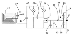
図6において、センサは電気装置の接点2の2つの極間に接続された電圧存在検出器34である。この検出器は直列に接続された2つの抵抗器35と36とを含む分圧器でなり、この分圧器の中間点には、ダイオード37を介して、トランジスタ38の制御極が接続されると共に、ダイオード37と制御極の接続点と抵抗器36の他端との間に、平滑用のコンデンサ39と制御極に与えられる電圧波形を整形する電圧クリッパー40とが接続されている。トランジスタ38は表示ランプ41を発光させ、表示ランプ43を発光させるトランジスタ42の制御信号を反転させる。こうして表示ランプ41と43とは電圧が存在するかしないかに応じて逆の点灯状態にされる。
【0041】
ダイオード27には電磁放射線を受信するようになっているアンテナとして設けられた電磁受信コイル11が接続されており、モニタ装置に整流された電流を供給するようになっている。ダイオード27の出力端に接続されたコンデンサ44はダイオードが整流した電流を平滑し、表示ランプ41及び43ならびにトランジスタ38及び42にDC電源電圧を供給する。
【0042】
図7の実施形態ではモニタ装置は、電磁受信コイル11とコンデンサ26によって構成された電磁放射線受信手段に接続された入力回路45と、この入力回路に接続された符号化回路46とを含む。この入力回路45は電磁放射線が受信されると、電源電圧VLを符号化回路46及び/又は表示手段に供給するようになっている。
【0043】
好適には、入力回路は電磁放射線が受信された時にクロック信号を示す信号CKを符号化回路に与える。特定の実施形態では、この信号CKによって符号化回路がリターン信号の変調手段を同期化するように符号化回路に命令することが可能となる。この信号CKは電磁放射線が搬送し、電気装置のモニタ装置向けとなっている信号の復調を実行するのにも使用できる。符号化回路は入力回路へ変調信号MDを供給し、負荷の変更を指令し、次に符号化回路内で定められる機能に従ってリターン信号を送るように入力回路へ変調信号MDを供給する。リターン信号の変調は位相変調でもよいし、振幅変調でもよいし、また周波数変調でもよい。
【0044】
図7の実施形態では符号化回路は制御信号48を供給するための少なくとも1つの出力端と、モニタ信号49を受信するための1つの入力端とを含む。この場合、制御信号48は発光ダイオード47に供給され、モニタ信号49はセンサ50によって供給される。
【0045】
図8には、本発明に係る入力回路の回路図が詳細に示されている。この入力回路は、電磁放射線を受信するように、電磁受信コイル11とコンデンサ26とによって構成された共振回路に接続されたダイオードブリッジ51を含む。ダイオードブリッジの出力端には、電源電圧VLを最大値に制限するための電圧制限器52が接続されている。平滑コンデンサ54に給電するようにダイオードブリッジ51の正の出力端には逆流防止ダイオード53が接続されている。そして、電源電圧VLは平滑コンデンサ54の両端から得られる。
【0046】
クロック信号CKを供給するために、クロック信号検出回路55が、ダイオードブリッジのAC入力端及び符号化回路に接続されている。このクロック信号CKは、特にリターン信号の位相変調が選択された場合に、変調信号を決定する目的を奏することができる。この変調信号MDは、変調信号を整形するための変調回路56及び電磁放射線受信手段の負荷インピーダンスを変化させるための手段へ供給される。この実施形態では、負荷インピーダンスを変えるための手段は、逆流防止ダイオード53の前のダイオードブリッジ51の出力端に接続された抵抗器58と直列なトランジスタ57を含む。トランジスタ57のターンオンが指令されると、抵抗器58はブリッジの出力端を導通させ、インピーダンスの変化を生じさせる。この負荷インピーダンスの変化によって電磁受信コイル11及びコンデンサ26によって受信される電磁放射線を変更でき、信号を発光手段に戻す。逆流防止ダイオード53はコンデンサが放電するのを防止し、給電の連続性を保証する。
【0047】
符号化回路は特に通信手段に対する戻し信号、すなわち、リターン信号における通信フレームの送信処理を可能にする。しかしながら、いくつかの装置が戻し信号、すなわちリターン信号を送信する可能性が高い場合、符号化回路は通信フレームの送受信を管理するための競合防止処理回路を含むことが有利である。例えば、符号化回路は所定数の同一の通信フレームを送信できる。好適には、少なくとも5つの同一フレームが送られる。
【0048】
図8の装置は符号化回路46の入力端に初期化信号を供給するための初期化回路86も含む。この初期化信号は、例えば電源電圧VLが上昇するたびに供給できる。
【0049】
図9は、モニタ信号49を受信するための入力端と、制御信号48を供給するための出力端とを備えた符号化回路46を示し、これら信号は1つ以上のモニタ信号又は制御信号を示す。これらの信号は入力端又は出力端で直接、もしくは図9に示されるように供給されたり、受信されたりする。これら信号はマルチプレクサ、デマルチプレクサ、信号シフトレジスタ又はシリアル化レジスタ、もしくはシリアル通信バスリンクのような信号プール回路を通過することもできる。符号化回路46には入力信号をプールするための入力プール回路87が接続されており、符号化回路46には出力信号を分離するための出力プール回路59が接続されている。
【0050】
符号化回路の制御信号48及びモニタ信号49を二進論理信号、数種の論理レベルを有する信号及び/又はアナログ信号とすることができる。
【0051】
従って、図9では表示装置60によって、電気装置の識別パラメータ又は設定パラメータを示すモニタ信号を符号化回路に供給できるようにしている。この識別パラメータは装置のシリアル番号、タイプ、定格又はサイズを表示できる。設定パラメータは電気装置の電流しきい値又は電圧しきい値、引外し遅延時間又は他のパラメータを表示できる。
【0052】
識別装置は、各装置のための独自の識別番号を記憶するためのメモリ88を含むことができる。この独自の識別番号は、装置の特徴及びシリアル番号と共に装置のタイプを画定するラベルの情報を含むことができる。この識別番号は、電気設備モニタ手段89を含む中央処理装置20で使用できる。この種の中央ユニットでは、表示インターフェースに対して画定されたアレイが識別番号をアルファニューメリックデータ又はグラフィックデータに変換するためのラベルサポート機能を含む。このデータは電気設備方式のダイナミック管理を実行するよう、識別パラメータ又は設定パラメータと共に使用できる。例えば、装置を特性の異なる別の装置に置換する場合、中央ユニットに表示される図又はアレイを自動的に更新する。
【0053】
例えば、メモリ88に記憶される独自の識別番号の他の機能を、装置の通信回路のアドレス指定機能又は独自のシリアル番号によるコピー防止装置において装置を識別するための機能とすることができる。
【0054】
電気装置の少なくとも1つのセンサの状態を決定するための装置61により、前記少なくとも1つのセンサの状態を示すモニタ信号を符号化回路に供給することが可能となっている。このセンサは特に接点の開状態又は閉状態、もしくは遮断器の引外し機構の状態を検出できる。このセンサは特に電気的な接点、位置センサ又は光ビームに対する変化、例えば前記ビームのブロック、反射又は変位に反応する光センサとすることができる。この種のセンサは装置62として表示されている。
【0055】
装置61及び62は、遮断器が引外しする種々の理由、特に熱もしくは長期遅延引外し、磁気的もしくは短期遅延引外し、又は差動もしくは接地保護引外しを示すセンサの状態も決定できる。
【0056】
少なくとも電気的な量を測定するための装置63により、前記少なくとも1つの電気量を示すモニタ信号を符号化回路に供給することが可能となっている。この電気量とは、特に電気的な位相、接地保護又は差動電流もしくは電圧、もしくは電流又は電圧のしきい値をオーバーシュートとすることができる。この電気量は測定用トランス、分圧器、ホール効果センサ又は磁気抵抗器によって測定できる。
【0057】
少なくとも1つの磁気量を測定するための装置64により、前記少なくとも1つの磁気量を示すモニタ信号を符号化回路へ供給することが可能となっている。この磁気量は磁界もしくは誘導磁界とすることができる。
【0058】
少なくとも1つの熱量を測定するための装置65によって、前記少なくとも1つの熱量を示すモニタ信号を符号化回路に供給できるようになっている。この量は特に電気装置のケースの内部の温度、接点温度、前記ケースの外部の周辺温度とすることができる。
【0059】
かかる信号を受信した際に、リモート中央処理装置は装置の特性の一部又はすべてを、例えばコンピュータのモニタに表示できる。
【0060】
通信装置66により符号化回路との間で信号を送受信することが可能となっている。この通信回路により、特に電気装置の他の回路との通信も可能となっている。通信装置をアドレス指定するために独自の識別番号を使用できる。
【0061】
表示装置67により、表示指令を示す信号を符号化回路から受信することが可能となっている。この装置は、特に発光ダイオード状をした1つ以上の表示ランプとすることができるし、又は電力消費量の少ない液晶表示のような表示装置68とすることもできる。
【0062】
作動装置69により電気装置の命令を示す信号を符号化回路から受信することが可能となっている。この種の装置は、電気装置の遠隔開放又は検査を命令することができる。この装置はリレー、トランジスタ又は例えばホトカプラーとして構成できる。
【0063】
装置内に収納された電磁放出装置85により、符号化回路から信号を送ることが可能となっている。この装置85の放出周波数は、電気装置10が受信するようになっている電磁放射線の周波数と異なっていることが好ましい。
【0064】
リモート給電される入力回路によって給電される電源VLから装置60〜69及び85を給電できることが好ましい。しかしながら、本発明の別の実施形態では、電気装置10の別の電源によって所定の装置を給電することもでき、電磁受信コイル11と電磁放出コイル15とによって電気的な絶縁が行われている。
【0065】
図10はスイッチボード、設備の一部、電気装置10及び本発明に係るモニタ装置の図を示す。この図では、電気装置10はその側壁70に配置された電磁受信コイル11を有する。電磁受信コイル11は、平坦であることが好ましい。レール状をした支持体72に取り付けできるモジュール式電気開閉装置のケース71内に電気装置10を収納することが好ましい。
【0066】
モニタ装置は、好適には、電気キャビネットの少なくとも1つの壁に配置された電磁放射線放出手段を含む。従って、図10では、少なくとも1つの電気装置10の配置に対する2つの対向する側壁73と74とに、モニタ装置の電磁放出コイル15が配置されている。特に発振回路14、処理回路17及び/又は電源回路18を含むケース75に電磁放出コイル15が接続されている。このケース75はレール状をした支持体72に取り付けできるモジュール式電気開閉装置ケースでもよい。電磁放出コイル15はケース75に別々に接続してもよいし、また、このケース75に接続する前に直列に接続してもよい。この実施形態では、電磁放射線16は平らな形状の電磁受信コイル11の平面に垂直な、ほぼ直線状の磁界ラインとなっている。
【0067】
図11は電気スイッチボード、設備の一部、電気装置10、図1の実施形態の別の変形例に係るモニタ装置の図を示す。このケースでは電磁放出コイル15はレール状をした少なくとも1つの支持体72に平行に配置された細長い形状となっており、支持体72は電磁受信コイル11を含む少なくとも1つの電気装置を受けるようになっている。この図では、2本のレール72の間に電磁放出コイル15が配置されている。
【0068】
図12及び13は本発明の別の実施形態を示す。この実施形態では、電気装置10は前記装置のバックプレート77に配置された電磁受信コイル11を含む。図13に示されるように、装置の内側78又は外側79において、バックプレート77に電磁受信コイル11を固定できる。このケースでは、電磁受信コイルは電磁放出コイル15を含む支持体に向くことができる。次にレール状をした支持体に取り付けできるモジュール式電気開閉装置を収納するために、ケース71内に電気装置10を収納することが好ましい。
【0069】
図12及び13の実施形態では、支持体が少なくとも1つの電気装置10に電磁放射線を放出するようになっている電磁放射線放出手段を含む。好適には、支持体はこの支持体の正面に配置された、数回巻かれた誘導ループ、すなわち誘導コイルを含む。支持体の本体は磁力線81を集中するために磁性材料から製造することが好ましい。
【0070】
好ましくは支持体は電気装置を支持するためにレール80状となっている。この支持体は電磁放出コイル15を含む中空部分82を正面に有する対称的なレールとなっていることが有利である。電磁放出コイル15の中心部分83は磁性材を有していてもよいし、有していなくてもよい。
【0071】
磁界軸線はレール80状をした支持体の長手方向に垂直となっていることが好ましい。しかしながら、別の実施形態では、レール80状をした支持体の長手方向に平行な磁界軸線を有するコイルを配置することが可能である。
【0072】
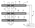
図14及び15は、図12及び13に係る装置及び支持体を含むモニタ装置及び設備の一部を示す。図14において、電気設備は電磁放出コイル15を含むレール80状をした支持体と、電磁放出コイル15に対向するバックプレートに電磁受信コイル11が配置された電気装置10とを備えた3つのモニタ装置13を含む。各電磁放出コイル15は発振器と処理回路とを備えた処理ユニット76に別々に接続されている。各モニタ装置の処理ユニット76は中央ユニット又は制御センターとも称される中央処理装置20に接続されている。この中央処理装置20は同じ電気スイッチボード又はキャビネット内のモニタ装置の近くに設けることができる。また、電気設備の別のモニタ装置からの信号を受信するように、離間した状態に設けることもできる。
【0073】
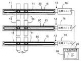
図15において、電気設備は電磁放出コイル15を含むレール80状の3つの支持体と、これら電磁放出コイル15に向いたバックプレートに電磁受信コイル11が配置された電気装置10を備えたモニタ装置13とを含む。3つの支持体の電磁放出コイル15は、発振器と処理回路とを備えた処理ユニット76に直列に接続されている。
【0074】
本発明の実施形態に係る電気設備は、配電システムに接続された装置又は例えば、前記装置、支持体又はモニタ装置を収納する電気キャビネット、スイッチボード又は密閉体及び中央処理装置に接続された装置の双方に関するものである。
【0075】
装置は特にスイッチ、遮断器、リレー、コンタクタ、遠隔制御スイッチ、タイムスイッチ、表示又は表示モジュール又は、例えば工業用もしくは家庭用自動化システムバスに接続された通信モジュールとすることができる。モジュール式の電気開閉装置内にモニタ装置を収納できる。
【0076】
【発明の効果】
以上の説明によって明らかなように、本発明によれば、電気装置内に内蔵される補助回路の使用を不要にし、電気的な絶縁を保証する電気装置、電気開閉装置の支持体及びモニタ装置、並びにこれらを内蔵する電気設備を提供することができる。
【図面の簡単な説明】
【図1】従来の電気装置及び設備の概略構成図。
【図2】本発明の第1実施形態に係る電気装置、モニタ装置及び設備の概略構成図。
【図3】本発明の第2実施形態に係る電気装置の概略構成図。
【図4】本発明の第3実施形態に係る電気装置の概略構成図。
【図5】本発明の第4実施形態に係る電気装置のモニタ装置の概略構成図。
【図6】本発明の第5実施形態に係る電気装置のモニタ装置の概略構成図。
【図7】本発明の第6実施形態に係る電気装置のモニタ装置の概略構成図。
【図8】図7の実施形態の第1の発展例に係る電気装置のモニタ装置の概略構成図。
【図9】図7及び8の実施形態の第2の発展例の概略構成図。
【図10】本発明の実施形態の別の第1変形例に係るモニタ装置及び電気装置の概略構成図。
【図11】本発明の実施形態の別の第2変形例に係るモニタ装置及び電気装置の概略構成図。
【図12】本発明の実施形態の第3の別の変形例に係る電気装置、支持体、モニタ装置及び電気設備の概略構成図。
【図13】図12の実施形態に係る装置及び支持体の側面概略構成図。
【図14】図12の実施形態に係る装置及び支持体を含む電気設備及びモニタ装置の別の実施形態の概略構成図。
【図15】図13の実施形態に係る装置及び支持体を含む電気設備及びモニタ装置の別の実施形態の概略構成図。
【符号の説明】
12,24,50 センサ
13 モニタ装置
15 電磁放射線放出コイル
15 電磁放射線
17 処理回路
21,25,28,47 発光ダイオード
22 遮断器
23 引外し装置
41,43 表示ランプ
45 入力回路
46 符号化回路
60,67,68 表示装置
66 通信装置
70 側壁
75 ケース
80 レール
82 中空部分[0001]
BACKGROUND OF THE INVENTION
The present invention relates to an electric device, a support for an electric switchgear, a monitor device, and an electric equipment incorporating them.
[0002]
[Prior art and problems to be solved by the invention]
Some conventional electrical devices, such as switches or circuit breakers, include an auxiliary circuit for remotely indicating their status. These auxiliary circuits are generally coupled to the sides of the electrical devices or are located within these electrical devices. These auxiliary circuits, as is well known, use contacts to display the status of the device in the electrical installation on site or remotely.
[0003]
Electrical equipment installations associated with the auxiliary circuit require a large amount of wiring, including a large number of connecting lines. Furthermore, when the electrical device is modular so as to fit into a cabinet or switch board provided with a rail-shaped support, the auxiliary circuit occupies a large number of modules. Since auxiliary circuits are generally used for display purposes, these auxiliary circuits must be electrically isolated from the main circuit of the electrical device. Thus, the auxiliary circuit includes a large sized connection terminal that is separated from the circuitry of the device with which it is associated.
[0004]
FIG. 1 is a schematic configuration diagram of a conventional electric device having an auxiliary circuit. In the figure, the first
[0005]
An object of the present invention is to provide an electric device that eliminates the use of an auxiliary circuit incorporated in the electric device and guarantees electrical insulation, a support and monitor device for the electric switchgear, and an electric equipment that incorporates them. There is.
[0006]
[Means for Solving the Problems]
The invention according to
The monitor device
Electromagnetic radiation receiving means connected to at least one sensor and adapted to receive electromagnetic radiation from the electromagnetic radiation emitting means;
A load changing means connected to the electromagnetic radiation receiving means and sending a monitor signal by changing the electromagnetic radiation when the electromagnetic radiation is received;
It is provided with.
[0007]
The invention according to
[0008]
According to a third aspect of the present invention, in the electrical device according to the first aspect, the monitor device includes at least one display device, and displays the state of at least one sensor when electromagnetic radiation is received by the electromagnetic radiation receiving means. Thus, the display device is supplied with power by electromagnetic radiation receiving means.
[0009]
The invention according to
[0010]
The invention according to
[0011]
According to a sixth aspect of the present invention, in the electric device according to the first aspect of the present invention, the electric device includes a switch and a sensor that supplies a signal indicating a state of the switch to the monitor device.
[0012]
The invention according to
[0013]
The invention according to claim 8 is the electric device according to
[0014]
The invention according to claim 9 is the electric device according to
[0015]
The invention according to
[0016]
According to an eleventh aspect of the present invention, in the support according to the tenth aspect, the electromagnetic radiation emitting means includes at least one induction coil having a plurality of turns arranged on the front surface of the support.
[0017]
The invention according to
[0018]
The invention according to
[0019]
The invention according to
The monitoring device for an electric switchgear according to
[0020]
According to a fifteenth aspect of the present invention, in the monitor device according to the fourteenth aspect, means for modulating and demodulating a signal indicating electromagnetic radiation that can be emitted from the electromagnetic radiation emitting means and performing at least one of encoding and decoding And a processing circuit including:
[0021]
According to a sixteenth aspect of the present invention, in the monitoring device according to the fifteenth aspect, the means for detecting a change in electromagnetic radiation emitted by the electromagnetic radiation emitting means and changeable by the monitoring device of at least one electric device is processed. A circuit is provided.
[0022]
The invention according to
[0023]
According to an eighteenth aspect of the present invention, in the monitor device according to the fourteenth aspect, the electromagnetic radiation emitting means is parallel to at least one support body in the form of a rail adapted to receive an electric device including electromagnetic radiation receiving means. And including at least one electromagnetic induction coil having an elongated shape.
[0024]
The invention according to
In an electrical installation with an electrical device connected to a power system,
At least one electrical device according to
At least one support comprising electromagnetic radiation receiving means for supporting at least one electrical device according to
15. At least one monitoring device according to
It is the electric equipment characterized by comprising.
[0025]
Other advantages and features of the present invention will become more apparent from the following description of specific embodiments of the invention, given by way of non-limiting example only and shown in the accompanying drawings.
[0026]
DETAILED DESCRIPTION OF THE INVENTION
Hereinafter, the present invention will be described in detail based on preferred embodiments shown in the drawings. In an apparatus according to an embodiment of the present invention, the monitor device includes electromagnetic radiation receiving means connected to at least one sensor. In particular, the electromagnetic radiation receiving means receives electromagnetic radiation from the electromagnetic radiation emitting means, receives electric power, or transmits a signal indicating the state of at least one element of the electric device detected by the sensor. It has become.
[0027]
FIG. 2 is a schematic configuration diagram of an outline of the first embodiment of the electric device, the monitor device, and the equipment according to the present invention. In FIG. 2, the
[0028]
The
[0029]
The
[0030]
The
[0031]
The
[0032]
In the embodiment shown in FIG. 3, the
[0033]
In FIG. 4, the
[0034]
Preferably, the
[0035]
In this embodiment, a change in the state of at least one
[0036]
In FIG. 5, the monitoring device for an electric device according to an embodiment of the present invention includes a resonance circuit including an
[0037]
Therefore, when the
[0038]
In this embodiment, as long as energy is supplied to the
[0039]
In order to effectively use the return signal, the
[0040]
In FIG. 6, the sensor is a
[0041]
The
[0042]
In the embodiment of FIG. 7, the monitoring device includes an
[0043]
Preferably, the input circuit provides a signal CK indicative of a clock signal to the encoding circuit when electromagnetic radiation is received. In a particular embodiment, this signal CK allows the encoding circuit to instruct the encoding circuit to synchronize the return signal modulation means. This signal CK can also be used to perform demodulation of a signal carried by electromagnetic radiation and intended for a monitoring device of an electrical device. The encoding circuit supplies a modulation signal MD to the input circuit, commands a load change, and then supplies the modulation signal MD to the input circuit to send a return signal according to a function defined in the encoding circuit. The modulation of the return signal may be phase modulation, amplitude modulation, or frequency modulation.
[0044]
In the embodiment of FIG. 7, the encoding circuit includes at least one output for supplying a
[0045]
FIG. 8 shows a detailed circuit diagram of the input circuit according to the present invention. The input circuit includes a
[0046]
In order to supply the clock signal CK, a clock signal detection circuit 55 is connected to the AC input terminal of the diode bridge and the encoding circuit. This clock signal CK can serve the purpose of determining the modulation signal, particularly when phase modulation of the return signal is selected. The modulation signal MD is supplied to a
[0047]
In particular, the encoding circuit enables transmission processing of a communication frame in a return signal to the communication means, that is, a return signal. However, if some devices are likely to send a return signal, i.e. a return signal, the encoding circuit advantageously includes a contention prevention processing circuit for managing the transmission and reception of communication frames. For example, the encoding circuit can transmit a predetermined number of identical communication frames. Preferably at least 5 identical frames are sent.
[0048]
The apparatus of FIG. 8 also includes an
[0049]
FIG. 9 shows an
[0050]
The
[0051]
Accordingly, in FIG. 9, the
[0052]
The identification device can include a
[0053]
For example, another function of the unique identification number stored in the
[0054]
A
[0055]
[0056]
By means of a
[0057]
By means of a
[0058]
A monitoring signal indicative of the at least one amount of heat can be supplied to the encoding circuit by a
[0059]
Upon receiving such a signal, the remote central processing unit can display some or all of the device characteristics, for example, on a computer monitor.
[0060]
The
[0061]
The
[0062]
The
[0063]
A signal can be sent from the encoding circuit by the
[0064]
It is preferable that the
[0065]
FIG. 10 shows a diagram of a switch board, part of equipment, an
[0066]
The monitoring device preferably includes electromagnetic radiation emitting means arranged on at least one wall of the electrical cabinet. Thus, in FIG. 10, the
[0067]
FIG. 11 shows a diagram of an electrical switch board, a piece of equipment, an
[0068]
12 and 13 show another embodiment of the present invention. In this embodiment, the
[0069]
In the embodiment of FIGS. 12 and 13, the support includes electromagnetic radiation emitting means adapted to emit electromagnetic radiation to at least one
[0070]
Preferably, the support is in the form of a
[0071]
The magnetic field axis is preferably perpendicular to the longitudinal direction of the support having a
[0072]
14 and 15 show a part of the monitoring device and equipment including the device and support according to FIGS. 12 and 13. In FIG. 14, the electrical equipment includes three monitors including a support in the shape of a
[0073]
In FIG. 15, the electrical equipment is a monitor device provided with three supports in the form of
[0074]
An electrical installation according to an embodiment of the present invention is an apparatus connected to a power distribution system or an apparatus connected to a central processing unit, for example, an electrical cabinet, switch board or sealing body that houses the apparatus, support or monitoring device. It is about both sides.
[0075]
The device can in particular be a switch, a circuit breaker, a relay, a contactor, a remote control switch, a time switch, a display or display module or a communication module connected eg to an industrial or home automation system bus. The monitor device can be stored in a modular electric switchgear.
[0076]
【The invention's effect】
As is apparent from the above description, according to the present invention, there is no need to use an auxiliary circuit incorporated in the electric device, and an electric device that guarantees electrical insulation, a support for the electric switchgear, and a monitor device, In addition, it is possible to provide an electrical facility incorporating these.
[Brief description of the drawings]
FIG. 1 is a schematic configuration diagram of a conventional electric device and equipment.
FIG. 2 is a schematic configuration diagram of an electric device, a monitor device, and equipment according to the first embodiment of the present invention.
FIG. 3 is a schematic configuration diagram of an electric device according to a second embodiment of the present invention.
FIG. 4 is a schematic configuration diagram of an electric device according to a third embodiment of the present invention.
FIG. 5 is a schematic configuration diagram of a monitoring device for an electric device according to a fourth embodiment of the present invention.
FIG. 6 is a schematic configuration diagram of a monitoring device for an electric device according to a fifth embodiment of the present invention.
FIG. 7 is a schematic configuration diagram of an electric device monitoring apparatus according to a sixth embodiment of the present invention.
8 is a schematic configuration diagram of a monitoring device for an electric device according to a first development example of the embodiment of FIG. 7;
9 is a schematic configuration diagram of a second development example of the embodiment of FIGS. 7 and 8. FIG.
FIG. 10 is a schematic configuration diagram of a monitor device and an electric device according to another first modification of the embodiment of the present invention.
FIG. 11 is a schematic configuration diagram of a monitor device and an electric device according to another second modification of the embodiment of the present invention.
FIG. 12 is a schematic configuration diagram of an electric device, a support, a monitor device, and electric equipment according to a third alternative example of the embodiment of the present invention.
13 is a schematic side view of the apparatus and support according to the embodiment of FIG.
14 is a schematic configuration diagram of another embodiment of an electrical installation and a monitoring device including the device and the support according to the embodiment of FIG. 12;
FIG. 15 is a schematic configuration diagram of another embodiment of the electrical equipment and the monitor device including the device and the support according to the embodiment of FIG. 13;
[Explanation of symbols]
12, 24, 50 sensors
13 Monitor device
15 Electromagnetic radiation emitting coil
15 Electromagnetic radiation
17 Processing circuit
21, 25, 28, 47 Light emitting diode
22 Circuit breaker
23 Tripping device
41, 43 Indicator lamp
45 Input circuit
46 Coding circuit
60, 67, 68 display device
66 Communication equipment
70 side walls
75 cases
80 rails
82 Hollow part
Claims (17)
前記モニタ装置は、電磁放射線(16)を発生させる電磁放射線放出手段(15)を有するものとして構成され、
さらに、前記電気装置は、
前記電気部品(2、22、23)の状態を検出する少なくとも1つのセンサ(12、24、34、50、60〜65)と、
前記電磁放射線放出手段(15)からの電磁放射線(16)を受信するようになされた電磁放射線受信手段(11)と、
をさらに備え、
前記少なくとも1つのセンサ(12)を前記電磁放射線受信手段(11)に接続し、且つ、電磁放射線を受信した時に電磁放射線(16)を変化させてモニタ信号を送る負荷変更手段(12、24、57、58)として機能するものとして構成し、
前記少なくとも1つのセンサ(12)と前記電磁放射線受信手段(11)との間に接続した少なくとも1つの表示装置(21、25、28、41、43、47、67、68)を含み、前記電磁放射線受信手段(11)によって電磁放射線(16)が受信された時に、前記少なくとも1つのセンサ(12)の状態を表示するように、前記電磁放射線受信手段(11)によって前記表示装置(21、25、28、41、43、47、67、68)に給電される
ことを特徴とする電気装置。In an electrical device comprising electrical components (2, 22, 23) and at least one monitor device of the electrical components,
The monitoring device is configured as having electromagnetic radiation emitting means (15) for generating electromagnetic radiation (16),
Furthermore, the electrical device comprises:
At least one sensor (12, 24, 34, 50, 60-65) for detecting the state of the electrical component (2, 22, 23);
Electromagnetic radiation receiving means (11) adapted to receive electromagnetic radiation (16) from said electromagnetic radiation emitting means (15);
Further comprising
Load changing means (12, 24,) for connecting the at least one sensor (12) to the electromagnetic radiation receiving means (11) and changing the electromagnetic radiation (16) and sending a monitor signal when the electromagnetic radiation is received. 57, 58)
Including at least one display device (21, 25, 28, 41, 43, 47, 67, 68) connected between the at least one sensor (12) and the electromagnetic radiation receiving means (11), When the electromagnetic radiation (16) is received by the radiation receiving means (11), the display device (21, 25) is displayed by the electromagnetic radiation receiving means (11) so as to display the state of the at least one sensor (12). , 28, 41, 43, 47, 67, 68).
前記モニタ装置は、電磁放射線(16)を発生させる電磁放射線放出手段(15)を有するものとして構成され、
さらに、前記電気装置は、
前記電気部品(2、22、23)の状態を検出する少なくとも1つのセンサ(12、24、34、50、60〜65)と、
前記電磁放射線放出手段(15)からの電磁放射線(16)を受信するようになされた電磁放射線受信手段(11)と、
をさらに備え、
前記少なくとも1つのセンサ(12)を前記電磁放射線受信手段(11)に接続し、且つ、電磁放射線を受信した時に電磁放射線(16)を変化させてモニタ信号を送る負荷変更手段(12、24、57、58)として機能するものとして構成し、
前記電磁放射線受信手段(11)が電気装置の少なくとも1つの側壁(70)に配置されている
ことを特徴とする電気装置。In an electrical device comprising electrical components (2, 22, 23) and at least one monitor device of the electrical components,
The monitoring device is configured as having electromagnetic radiation emitting means (15) for generating electromagnetic radiation (16),
Furthermore, the electrical device comprises:
At least one sensor (12, 24, 34, 50, 60-65) for detecting the state of the electrical component (2, 22, 23);
Electromagnetic radiation receiving means (11) adapted to receive electromagnetic radiation (16) from said electromagnetic radiation emitting means (15);
Further comprising
Load changing means (12, 24,) for connecting the at least one sensor (12) to the electromagnetic radiation receiving means (11) and changing the electromagnetic radiation (16) and sending a monitor signal when the electromagnetic radiation is received. 57, 58)
An electrical device characterized in that the electromagnetic radiation receiving means (11) is arranged on at least one side wall (70) of the electrical device.
前記モニタ装置は、電磁放射線(16)を発生させる電磁放射線放出手段(15)を有するものとして構成され、
さらに、前記電気装置は、
前記電気部品(2、22、23)の状態を検出する少なくとも1つのセンサ(12、24、34、50、60〜65)と、
前記電磁放射線放出手段(15)からの電磁放射線(16)を受信するようになされた電磁放射線受信手段(11)と、
をさらに備え、
前記少なくとも1つのセンサ(12)を前記電磁放射線受信手段(11)に接続し、且つ、電磁放射線を受信した時に電磁放射線(16)を変化させてモニタ信号を送る負荷変更手段(12、24、57、58)として機能するものとして構成し、
前記モニタ装置が前記電磁放射線受信手段(11)に接続された入力回路(45)と、前記入力回路に接続された符号化回路(46)とを備えた
ことを特徴とする電気装置。In an electrical device comprising electrical components (2, 22, 23) and at least one monitor device of the electrical components,
The monitoring device is configured as having electromagnetic radiation emitting means (15) for generating electromagnetic radiation (16),
Furthermore, the electrical device comprises:
At least one sensor (12, 24, 34, 50, 60-65) for detecting the state of the electrical component (2, 22, 23);
Electromagnetic radiation receiving means (11) adapted to receive electromagnetic radiation (16) from said electromagnetic radiation emitting means (15);
Further comprising
Load changing means (12, 24,) for connecting the at least one sensor (12) to the electromagnetic radiation receiving means (11) and changing the electromagnetic radiation (16) and sending a monitor signal when the electromagnetic radiation is received. 57, 58)
The electrical apparatus characterized in that the monitor device comprises an input circuit (45) connected to the electromagnetic radiation receiving means (11) and an encoding circuit (46) connected to the input circuit.
前記モニタ装置は、電磁放射線(16)を発生させる電磁放射線放出手段(15)を有するものとして構成され、
さらに、前記電気装置は、
前記電気部品(2、22、23)の状態を検出する少なくとも1つのセンサ(12、24、34、50、60〜65)と、
前記電磁放射線放出手段(15)からの電磁放射線(16)を受信するようになされた電磁放射線受信手段(11)と、
をさらに備え、
前記少なくとも1つのセンサ(12)を前記電磁放射線受信手段(11)に接続し、且つ、電磁放射線を受信した時に電磁放射線(16)を変化させてモニタ信号を送る負荷変更手段(12、24、57、58)として機能するものとして構成し、
モジュール式電気開閉装置のケース(71)内に配置されている
ことを特徴とする電気装置。In an electrical device comprising electrical components (2, 22, 23) and at least one monitor device of the electrical components,
The monitoring device is configured as having electromagnetic radiation emitting means (15) for generating electromagnetic radiation (16),
Furthermore, the electrical device comprises:
At least one sensor (12, 24, 34, 50, 60-65) for detecting the state of the electrical component (2, 22, 23);
Electromagnetic radiation receiving means (11) adapted to receive electromagnetic radiation (16) from said electromagnetic radiation emitting means (15);
Further comprising
Load changing means (12, 24,) for connecting the at least one sensor (12) to the electromagnetic radiation receiving means (11) and changing the electromagnetic radiation (16) and sending a monitor signal when the electromagnetic radiation is received. 57, 58)
An electric device, which is arranged in a case (71) of a modular electric switchgear.
前記電磁放射線放出手段(15)から放出できる電磁放射線(16)を示す信号を変調し、復調し、符号化及び復号化の少なくとも一方を行うための手段を含む処理回路(17)を備えた
ことを特徴とするモニタ装置。The electromagnetic radiation emitting means (15, 75, 76) for emitting electromagnetic radiation (16) to at least one electrical device (10) according to claim 1, comprising the electromagnetic radiation receiving means (11),
A processing circuit (17) including means for modulating and demodulating a signal indicating electromagnetic radiation (16) that can be emitted from the electromagnetic radiation emitting means (15) and performing at least one of encoding and decoding; A monitor device characterized by the above.
前記電磁放射線放出手段が放出し、少なくとも1つの電気装置(10)のモニタ装置により変更できる電磁放射線(16)の変化を検出するための手段を、前記処理回路(17)が備えた、
ことを特徴とするモニタ装置。The electromagnetic radiation emitting means (15, 75, 76) for emitting electromagnetic radiation (16) to at least one electrical device (10) according to claim 1, comprising the electromagnetic radiation receiving means (11),
The processing circuit (17) comprises means for detecting a change in electromagnetic radiation (16) emitted by the electromagnetic radiation emitting means and changeable by a monitoring device of at least one electrical device (10),
A monitor device characterized by that.
前記電磁放射線放出手段(15)を含む少なくとも1つの側壁(73、74)を有する密閉体を備えた、
ことを特徴とするモニタ装置。The electromagnetic radiation emitting means (15, 75, 76) for emitting electromagnetic radiation (16) to at least one electrical device (10) according to claim 1, comprising the electromagnetic radiation receiving means (11),
A sealing body having at least one side wall (73, 74) containing said electromagnetic radiation emitting means (15);
A monitor device characterized by that.
前記電磁放射線放出手段(15)が前記電磁放射線受信手段(11)を含む電気装置(10)を受けるようになっているレール状をした、少なくとも1つの支持体(72)に平行に配置された細長い形状の少なくとも1つの電磁誘導コイルを含む、
ことを特徴とするモニタ装置。The electromagnetic radiation emitting means (15, 75, 76) for emitting electromagnetic radiation (16) to at least one electrical device (10) according to claim 1, comprising the electromagnetic radiation receiving means (11). An elongated shape arranged in parallel to at least one support (72) in the form of a rail in which the radiation emitting means (15) is adapted to receive an electrical device (10) comprising said electromagnetic radiation receiving means (11). Including at least one electromagnetic induction coil
A monitor device characterized by that.
電磁放射線受信手段(11)を含む請求項1乃至4の1つに記載の少なくとも1つの電気装置(10)と、
請求項9に記載の前記少なくとも1つの電気装置を支持するための電磁放射線受信手段(11)を含む少なくとも1つの支持体と、
電磁放射線受信手段(11)を含む前記少なくとも1つの電気装置(10)をモニタするための請求項13乃至16の1つに記載の少なくとも1つのモニタ装置と、
を備えたことを特徴とする電気設備。In an electrical installation with an electrical device connected to a power system,
At least one electrical device (10) according to one of the preceding claims comprising electromagnetic radiation receiving means (11);
At least one support comprising electromagnetic radiation receiving means (11) for supporting the at least one electrical device according to claim 9;
At least one monitoring device according to one of claims 13 to 16 for monitoring said at least one electrical device (10) comprising electromagnetic radiation receiving means (11);
Electrical equipment characterized by comprising
Applications Claiming Priority (2)
| Application Number | Priority Date | Filing Date | Title |
|---|---|---|---|
| FR0010417A FR2812962B1 (en) | 2000-08-08 | 2000-08-08 | ELECTRICAL APPARATUS COMPRISING A CONTROL DEVICE, SUPPORT AND MONITORING DEVICE FOR SUCH AN APPARATUS, AND ELECTRICAL INSTALLATION COMPRISING SAME |
| FR0010417 | 2000-08-08 |
Publications (2)
| Publication Number | Publication Date |
|---|---|
| JP2002150896A JP2002150896A (en) | 2002-05-24 |
| JP4812977B2 true JP4812977B2 (en) | 2011-11-09 |
Family
ID=8853386
Family Applications (1)
| Application Number | Title | Priority Date | Filing Date |
|---|---|---|---|
| JP2001239005A Expired - Lifetime JP4812977B2 (en) | 2000-08-08 | 2001-08-07 | ELECTRIC DEVICE, SUPPORTING AND MONITORING DEVICE FOR ELECTRIC SWITCHING DEVICE, AND ELECTRIC EQUIPMENT CONTAINING THEM |
Country Status (8)
| Country | Link |
|---|---|
| US (1) | US6961005B2 (en) |
| EP (2) | EP1179827B1 (en) |
| JP (1) | JP4812977B2 (en) |
| CN (2) | CN1246815C (en) |
| AT (1) | ATE456144T1 (en) |
| DE (1) | DE60141105D1 (en) |
| ES (1) | ES2336421T3 (en) |
| FR (1) | FR2812962B1 (en) |
Families Citing this family (51)
| Publication number | Priority date | Publication date | Assignee | Title |
|---|---|---|---|---|
| FR2846783B1 (en) * | 2002-11-06 | 2005-01-28 | Schneider Electric Ind Sas | METHOD AND DEVICE FOR CONTROLLING A SWITCH DEVICE |
| DE10258919A1 (en) * | 2002-12-17 | 2004-07-01 | Abb Patent Gmbh | Device, system and method for signaling the switching position of a switching device |
| DE102004006987B3 (en) * | 2004-01-14 | 2005-08-04 | Dehn + Söhne Gmbh + Co. Kg | Arrangement for overvoltage protection device state monitoring, recording, especially in low voltage networks/information technology, short-circuits, interrupts or detunes transponder antenna circuit for overvoltage protection device fault |
| EP1562272B1 (en) * | 2004-01-14 | 2016-09-07 | Dehn + Söhne Gmbh + Co. Kg | Arrangement for checking and recording of the status of an overvoltage protection device, particularly for installation in low-voltage networks or information systems |
| US8134445B2 (en) * | 2004-04-20 | 2012-03-13 | Cooper Technologies Company | RFID open fuse indicator, system, and method |
| US7369029B2 (en) * | 2004-04-20 | 2008-05-06 | Cooper Technologies Company | Wireless communication fuse state indicator system and method |
| US8169331B2 (en) * | 2004-09-10 | 2012-05-01 | Cooper Technologies Company | Circuit protector monitoring assembly |
| US20060077608A1 (en) | 2004-09-10 | 2006-04-13 | Speno Timothy H | Multifunctional response tool, method and system for circuit protector management |
| US20070194942A1 (en) * | 2004-09-10 | 2007-08-23 | Darr Matthew R | Circuit protector monitoring assembly, system and method |
| US20060122473A1 (en) * | 2004-10-13 | 2006-06-08 | Kill Robert A | Wireless patch temperature sensor system |
| US7240560B2 (en) * | 2004-10-18 | 2007-07-10 | Silverbrook Research Pty Ltd | Pressure sensor with remote power source |
| US20060087397A1 (en) * | 2004-10-26 | 2006-04-27 | Cooper Technologies Company | Fuse state indicating optical circuit and system |
| KR101136889B1 (en) * | 2005-07-12 | 2012-04-20 | 메사추세츠 인스티튜트 오브 테크놀로지 | Wireless non-radiative energy transfer |
| FR2893745B1 (en) * | 2005-11-22 | 2007-12-21 | Schneider Electric Ind Sas | DEVICE AND METHOD FOR MONITORING THE POSITION OF AT LEAST ONE MOBILE PART OF A PLURALITY OF ELECTRICAL DEVICES AND TABLE INCORPORATING SUCH A DEVICE |
| FR2893742B1 (en) * | 2005-11-22 | 2007-12-21 | Schneider Electric Ind Sas | MONITORING DEVICE AND METHOD FOR ELECTRIC C EQUIPMENT |
| EP1808879A1 (en) * | 2005-12-22 | 2007-07-18 | Siemens Aktiengesellschaft | System for contactless assessment of condition |
| FR2901426B1 (en) * | 2006-05-19 | 2008-09-12 | Schneider Electric Ind Sas | POSITION MONITORING DEVICE OF A MOBILE PART OF AN ELECTRIC SWITCH DEVICE |
| EP1936905B1 (en) * | 2006-12-19 | 2014-09-17 | Unify GmbH & Co. KG | Method for operating a VoIP terminal and VoIP terminal |
| DE102007006461A1 (en) * | 2007-02-05 | 2008-08-21 | Siemens Ag | Energy distribution device, in particular low-voltage power distribution device, and method for authenticating a power distribution device |
| US7791506B2 (en) * | 2007-03-30 | 2010-09-07 | Zf Friedrichshafen Ag | Configurable networked user interface and switch pack |
| DE102008011920A1 (en) * | 2008-02-29 | 2009-09-10 | Moeller Gmbh | Arrangement for supplying at least one device in a control cabinet, a distribution unit or an installation housing with auxiliary power |
| US8581542B2 (en) * | 2008-09-08 | 2013-11-12 | Qualcomm Incorporated | Receive antenna arrangement for wireless power |
| WO2010038596A1 (en) * | 2008-10-03 | 2010-04-08 | Semiconductor Energy Laboratory Co., Ltd. | Modulation circuit and semiconductor device including the same |
| EP2452415B1 (en) | 2009-07-08 | 2015-09-02 | ABB Research Ltd. | Bus condition monitoring system |
| FR2954578B1 (en) * | 2009-12-22 | 2014-07-04 | Schneider Electric Ind Sas | METHOD OF CONTROLLING AN ACTUATING ASSEMBLY COMPRISING AN ELECTROMAGNETIC ACTUATOR AND ACTUATING ASSEMBLY FOR IMPLEMENTING SUCH A METHOD |
| DE102011011508B4 (en) * | 2010-12-17 | 2012-07-12 | Dehn + Söhne Gmbh + Co. Kg | System for condition control and data logging of interchangeable, in particular plugged overvoltage devices |
| US8805193B2 (en) * | 2011-02-17 | 2014-08-12 | Avery Dennison Corporation | Remotely powered optical output labels |
| DE102011110252A1 (en) | 2011-06-21 | 2012-12-27 | Phoenix Contact Gmbh & Co. Kg | Condition control or diagnostic system |
| US9054516B2 (en) * | 2011-07-20 | 2015-06-09 | Siemens Industry, Inc. | Circuit breaker trip notification systems and methods |
| DE102012000411B4 (en) * | 2012-01-12 | 2018-03-01 | Phoenix Contact Gmbh & Co. Kg | Inductive energy transformer |
| DE102012000408A1 (en) | 2012-01-12 | 2013-07-18 | Phoenix Contact Gmbh & Co. Kg | Resonant inductive power supply device |
| DE102012000409A1 (en) | 2012-01-12 | 2013-07-18 | Phoenix Contact Gmbh & Co. Kg | Modular data system with inductive energy transfer |
| DE102012110170B4 (en) * | 2012-10-24 | 2018-05-24 | Phoenix Contact Gmbh & Co. Kg | Modular bus system for the transmission of data and / or energy |
| US9331746B2 (en) * | 2012-12-19 | 2016-05-03 | Eaton Corporation | System and method for providing information to and/or obtaining information from a component of an electrical distribution system |
| FR3011674B1 (en) * | 2013-10-07 | 2017-04-28 | Schneider Electric Ind Sas | ELECTRICAL SWITCHING ASSEMBLY AND METHOD FOR CONTROLLING ONE OR MORE SWITCHING DEVICES BELONGING TO SUCH A SWITCHING ASSEMBLY |
| SG2013094115A (en) | 2013-12-19 | 2015-07-30 | Schneider Electric South East Asia Hq Pte Ltd | Trigger actuator for a switching device |
| US9729201B2 (en) * | 2014-04-24 | 2017-08-08 | Empire Technology Development Llc | Broadcasting a message using modulated power |
| US10149933B2 (en) | 2014-07-25 | 2018-12-11 | Minnetronix, Inc. | Coil parameters and control |
| US9855376B2 (en) | 2014-07-25 | 2018-01-02 | Minnetronix, Inc. | Power scaling |
| US10342908B2 (en) | 2015-01-14 | 2019-07-09 | Minnetronix, Inc. | Distributed transformer |
| DE102016100534A1 (en) | 2015-01-16 | 2016-07-21 | Vlad BLUVSHTEIN | Data transmission in a transcutaneous energy transmission system |
| DE102015101671A1 (en) * | 2015-02-05 | 2016-08-11 | Osram Opto Semiconductors Gmbh | Method and device for checking an optoelectronic component |
| FR3032834B1 (en) * | 2015-02-12 | 2018-11-09 | Legrand France | ELECTRICAL APPARATUS, SYSTEMS COMPRISING SUCH AN ELECTRIC APPARATUS AND METHODS IMPLEMENTED IN SUCH SYSTEMS |
| US10193395B2 (en) | 2015-04-14 | 2019-01-29 | Minnetronix, Inc. | Repeater resonator |
| NL2015736B1 (en) | 2015-11-06 | 2017-05-24 | Liandon B V | System for monitoring electric current in a network, and electrical fuse thereof. |
| CN105652197B (en) * | 2016-03-13 | 2018-08-24 | 浙江展邦电子科技有限公司 | A kind of Portable electromagnetic relay tester with wireless communication function |
| FR3067528B1 (en) * | 2017-06-13 | 2020-10-09 | Continental Automotive France | REMOTE POWER SUPPLY, POSITION SENSOR AND WIRELESS COMMUNICATION DEVICE FOR DOOR DEPLOYING HANDLES |
| FR3067529B1 (en) * | 2017-06-13 | 2019-06-28 | Continental Automotive France | TELE-POWER, POSITION SENSOR AND WIRELESS COMMUNICATION DEVICE FOR A MOTOR VEHICLE DEPLOYING DOOR HANDLE |
| FR3077687B1 (en) * | 2018-02-05 | 2020-10-16 | Hager Electro Sas | DEVICE FOR MONITORING AT LEAST ONE FUNCTION AND / OR STATE AND / OR PARAMETERS OF AN ELECTRICAL APPLIANCE OR OF AN ELECTRICAL PANEL, AND ELECTRICAL PANEL INCLUDING ITS DEVICE |
| EP3671797B1 (en) * | 2018-12-18 | 2021-05-26 | Schneider Electric Industries SAS | Safety switch device |
| EP4297056A1 (en) * | 2022-06-24 | 2023-12-27 | Murrelektronik GmbH | Electrical fuse for securing the energy distribution in an industrial installation |
Family Cites Families (16)
| Publication number | Priority date | Publication date | Assignee | Title |
|---|---|---|---|---|
| US3689885A (en) * | 1970-09-15 | 1972-09-05 | Transitag Corp | Inductively coupled passive responder and interrogator unit having multidimension electromagnetic field capabilities |
| US3914762A (en) * | 1973-12-27 | 1975-10-21 | Rca Corp | Electronic identification system |
| US4782341A (en) * | 1983-07-01 | 1988-11-01 | Rockwell International Corporation | Meter data gathering and transmission system |
| JPS60127628A (en) * | 1983-12-12 | 1985-07-08 | 日本電気株式会社 | Circuit breaker with buzzer containing type display lamp |
| EP0309201B1 (en) * | 1987-09-22 | 1993-05-26 | Hitachi Maxell Ltd. | Method and system of communication for a non-contact ic card |
| US5305008A (en) * | 1991-08-12 | 1994-04-19 | Integrated Silicon Design Pty. Ltd. | Transponder system |
| US5198807A (en) * | 1989-05-26 | 1993-03-30 | Trovan Limited | Method and apparatus for producing a subcarrier signal for transmission by an inductively coupled transponder |
| DE4112625A1 (en) * | 1991-04-18 | 1992-10-22 | Fraunhofer Ges Forschung | Testing function of switching device activated by magnetic field, e.g. in machine tool - applying compensating magnetic field and checking that switch is deactivated |
| US5309310A (en) * | 1992-01-21 | 1994-05-03 | Felchar Manufacturing Corporation | Combined ground fault interrupter circuit and remote control on/off device |
| US5628252A (en) * | 1993-06-17 | 1997-05-13 | Power Superconductor Applications Co. | Method and apparatus for combined levitation and guidance along guideway curvature in electrodynamic magnetically levitated high speed vehicle |
| US5541574A (en) * | 1993-12-22 | 1996-07-30 | Palomar Technologies Corporation | Transponder system for communicating with a vehicle tire |
| US5905442A (en) * | 1996-02-07 | 1999-05-18 | Lutron Electronics Co., Inc. | Method and apparatus for controlling and determining the status of electrical devices from remote locations |
| US5861683A (en) * | 1997-05-30 | 1999-01-19 | Eaton Corporation | Panelboard for controlling and monitoring power or energy |
| US6025783A (en) * | 1998-04-30 | 2000-02-15 | Trw Vehicle Safety Systems Inc. | Wireless switch detection system |
| JP3077686B2 (en) * | 1998-12-16 | 2000-08-14 | 日新電機株式会社 | Circuit breaker circuit inspection device |
| US6720866B1 (en) * | 1999-03-30 | 2004-04-13 | Microchip Technology Incorporated | Radio frequency identification tag device with sensor input |
-
2000
- 2000-08-08 FR FR0010417A patent/FR2812962B1/en not_active Expired - Fee Related
-
2001
- 2001-07-26 ES ES01410095T patent/ES2336421T3/en not_active Expired - Lifetime
- 2001-07-26 AT AT01410095T patent/ATE456144T1/en not_active IP Right Cessation
- 2001-07-26 DE DE60141105T patent/DE60141105D1/en not_active Expired - Lifetime
- 2001-07-26 EP EP01410095A patent/EP1179827B1/en not_active Expired - Lifetime
- 2001-07-26 EP EP09354011A patent/EP2068333A3/en not_active Withdrawn
- 2001-07-31 US US09/917,757 patent/US6961005B2/en not_active Expired - Lifetime
- 2001-08-03 CN CNB011245360A patent/CN1246815C/en not_active Expired - Fee Related
- 2001-08-03 CN CNB2004100558809A patent/CN100375985C/en not_active Expired - Fee Related
- 2001-08-07 JP JP2001239005A patent/JP4812977B2/en not_active Expired - Lifetime
Also Published As
| Publication number | Publication date |
|---|---|
| CN1567396A (en) | 2005-01-19 |
| EP1179827B1 (en) | 2010-01-20 |
| DE60141105D1 (en) | 2010-03-11 |
| CN100375985C (en) | 2008-03-19 |
| JP2002150896A (en) | 2002-05-24 |
| CN1337657A (en) | 2002-02-27 |
| FR2812962B1 (en) | 2004-09-24 |
| US6961005B2 (en) | 2005-11-01 |
| US20020021226A1 (en) | 2002-02-21 |
| FR2812962A1 (en) | 2002-02-15 |
| EP2068333A2 (en) | 2009-06-10 |
| ATE456144T1 (en) | 2010-02-15 |
| EP1179827A1 (en) | 2002-02-13 |
| EP2068333A3 (en) | 2009-06-17 |
| CN1246815C (en) | 2006-03-22 |
| ES2336421T3 (en) | 2010-04-13 |
Similar Documents
| Publication | Publication Date | Title |
|---|---|---|
| JP4812977B2 (en) | ELECTRIC DEVICE, SUPPORTING AND MONITORING DEVICE FOR ELECTRIC SWITCHING DEVICE, AND ELECTRIC EQUIPMENT CONTAINING THEM | |
| JP5202521B2 (en) | AC current sensor for measuring AC current in a wire and a display system including such a sensor | |
| CN101371415B (en) | Wireless system for one or more electrical switching apparatus | |
| CA2639668C (en) | Inductively powered power bus apparatus | |
| US6133724A (en) | Remote light indication fault indicator with a timed reset circuit and a manual reset circuit | |
| US6133723A (en) | Fault indicator having remote light indication of fault detection | |
| JP6136015B2 (en) | Distribution panel system, energy management system, distribution panel, circuit breaker, and adapter | |
| SE537691C2 (en) | Wireless sensor device for a high voltage environment and system incorporating such | |
| JP5754750B2 (en) | Wireless sensor terminal | |
| CN110967619A (en) | Detection circuit, circuit detection and control method | |
| JP2010091581A (en) | Device for measuring leakage current state of low-voltage electrical facility | |
| JP3525178B2 (en) | Apparatus for testing electric drives | |
| KR102132920B1 (en) | Power monitoring system including electrical power saving device | |
| JP6249211B2 (en) | Communication device, wiring breaker including the same, and distribution board | |
| CN215646630U (en) | Zero-crossing detection circuit, drive circuit, circuit board, electronic equipment and cooking appliance | |
| US9455564B2 (en) | Current and voltage module and methods of monitoring current and voltage in power distribution systems | |
| KR102132919B1 (en) | Power monitoring system including electrical power saving device | |
| KR101037011B1 (en) | Reset circuit of indicating fault for power disribution pannel | |
| JPS6228105Y2 (en) | ||
| JP2000002735A (en) | Leakage check device | |
| JP2005129439A (en) | Conduction state detecting device by radio tag | |
| CZ8944U1 (en) | Voltage indicator for alternating current high-voltage systems | |
| JP2010139368A (en) | Watt-hour meter |
Legal Events
| Date | Code | Title | Description |
|---|---|---|---|
| A621 | Written request for application examination |
Free format text: JAPANESE INTERMEDIATE CODE: A621 Effective date: 20080331 |
|
| A977 | Report on retrieval |
Free format text: JAPANESE INTERMEDIATE CODE: A971007 Effective date: 20100528 |
|
| A131 | Notification of reasons for refusal |
Free format text: JAPANESE INTERMEDIATE CODE: A131 Effective date: 20100625 |
|
| A521 | Request for written amendment filed |
Free format text: JAPANESE INTERMEDIATE CODE: A523 Effective date: 20100927 |
|
| A131 | Notification of reasons for refusal |
Free format text: JAPANESE INTERMEDIATE CODE: A131 Effective date: 20110311 |
|
| A601 | Written request for extension of time |
Free format text: JAPANESE INTERMEDIATE CODE: A601 Effective date: 20110613 |
|
| A602 | Written permission of extension of time |
Free format text: JAPANESE INTERMEDIATE CODE: A602 Effective date: 20110616 |
|
| A521 | Request for written amendment filed |
Free format text: JAPANESE INTERMEDIATE CODE: A523 Effective date: 20110708 |
|
| TRDD | Decision of grant or rejection written | ||
| A01 | Written decision to grant a patent or to grant a registration (utility model) |
Free format text: JAPANESE INTERMEDIATE CODE: A01 Effective date: 20110729 |
|
| A01 | Written decision to grant a patent or to grant a registration (utility model) |
Free format text: JAPANESE INTERMEDIATE CODE: A01 |
|
| A61 | First payment of annual fees (during grant procedure) |
Free format text: JAPANESE INTERMEDIATE CODE: A61 Effective date: 20110824 |
|
| R150 | Certificate of patent or registration of utility model |
Ref document number: 4812977 Country of ref document: JP Free format text: JAPANESE INTERMEDIATE CODE: R150 Free format text: JAPANESE INTERMEDIATE CODE: R150 |
|
| FPAY | Renewal fee payment (event date is renewal date of database) |
Free format text: PAYMENT UNTIL: 20140902 Year of fee payment: 3 |
|
| R250 | Receipt of annual fees |
Free format text: JAPANESE INTERMEDIATE CODE: R250 |
|
| R250 | Receipt of annual fees |
Free format text: JAPANESE INTERMEDIATE CODE: R250 |
|
| R250 | Receipt of annual fees |
Free format text: JAPANESE INTERMEDIATE CODE: R250 |
|
| R250 | Receipt of annual fees |
Free format text: JAPANESE INTERMEDIATE CODE: R250 |
|
| R250 | Receipt of annual fees |
Free format text: JAPANESE INTERMEDIATE CODE: R250 |
|
| R250 | Receipt of annual fees |
Free format text: JAPANESE INTERMEDIATE CODE: R250 |
|
| R250 | Receipt of annual fees |
Free format text: JAPANESE INTERMEDIATE CODE: R250 |
|
| EXPY | Cancellation because of completion of term |