JP4811368B2 - Locking structure of sliding door - Google Patents
Locking structure of sliding door Download PDFInfo
- Publication number
- JP4811368B2 JP4811368B2 JP2007192626A JP2007192626A JP4811368B2 JP 4811368 B2 JP4811368 B2 JP 4811368B2 JP 2007192626 A JP2007192626 A JP 2007192626A JP 2007192626 A JP2007192626 A JP 2007192626A JP 4811368 B2 JP4811368 B2 JP 4811368B2
- Authority
- JP
- Japan
- Prior art keywords
- sliding door
- locking
- unlocking
- lock
- frame
- Prior art date
- Legal status (The legal status is an assumption and is not a legal conclusion. Google has not performed a legal analysis and makes no representation as to the accuracy of the status listed.)
- Expired - Fee Related
Links
Images
Landscapes
- Wing Frames And Configurations (AREA)
Description
本発明は、建物の開口に外付けで開閉自在に取り付けられる引き戸の施開錠構造に関する。 The present invention relates to a locking / unlocking structure for a sliding door that is externally attached to an opening of a building so as to be freely opened and closed.
建物の開口を開き戸から引き戸に改装する場合の壁解体などの大掛かりな工事を避けるために、開口上部に壁面から突出させ、水平に延出させて上レールを取り付け、上レールに対向する開口下部に下レールを取り付け、上レールと下レールとの間に引き戸を走行自在に取り付け、建物の開口に外付けで開閉自在に取り付け可能な引き戸、いわゆるアウトセット引き戸を本出願人は先に提案している。 In order to avoid large-scale work such as wall demolition when remodeling the opening of a building from an open door to a sliding door, the upper part of the opening protrudes from the wall surface, extends horizontally, and the upper rail is attached, and the lower part of the opening facing the upper rail The applicant previously proposed a sliding door that can be attached to the opening of the building so that it can be opened and closed externally, so-called an outset sliding door. ing.
そして、本出願人は、上記引き戸には、市販の錠では施錠不可能という問題があり、この問題を改善する施錠構造を提案してもいる(特許文献1)。 The applicant has a problem that the sliding door cannot be locked with a commercially available lock, and has proposed a locking structure that improves this problem (Patent Document 1).
特許文献1に記載された施錠構造では、開口の内周に設けられた開口枠にロック装置を装着し、ロック装置には、レバー操作により引き戸の厚さ方向に出入りするロックバーを設け、引き戸の側部に表裏に貫通する貫通穴を形成し、貫通穴の裏面側にロックバー挿通金具を、表面側に貫通穴覆いプレートをそれぞれ配置し、両者を結合して引き戸に固定し、引き戸の裏面側ではロック装置のレバーを操作することにより、ロックバーをロックバー挿通金具のロック穴に係合させてロックさせ、ロック穴からロックバーを引き抜いてロックを解除するようにしている。錠を簡易な構造により実現している。
しかしながら、特許文献1に記載された施錠構造では、非常時などに備え、引き戸の表面側から解除手段を操作してロックを解除することができるようにしているが、解除手段は、具体的には、貫通穴覆いプレートにロック穴に連通して形成された解除穴であり、ロック解除は、解除穴からピンなどを挿通してロックバーを押し戻すことによって行われる。解除穴は非常に小さく、このように小さい解除穴にピンを差し込むこと、また、細いピンによってロックバーを押し戻す必要があること、さらに、ピンを常時携帯しておくことができないなどの不都合があり、引き戸の表面側からのロック解除は容易であるとはいえなかった。特に、高齢者や子供などには、引き戸の表面側からのロック解除は操作しにくい。
However, in the locking structure described in
本発明は、以上の通りの事情に鑑みてなされたものであり、簡易な構造の錠としたまま、引き戸の表裏両側からの施開錠が容易である引き戸の施開錠構造を提供することを課題としている。 The present invention has been made in view of the circumstances as described above, and provides a sliding door locking and unlocking structure that can be easily locked and unlocked from both the front and back sides of the sliding door while keeping the lock of a simple structure. Is an issue.
本発明は、上記の課題を解決するために、以下の特徴を有する。 The present invention has the following features in order to solve the above problems.
すなわち、第1の発明は、建物の開口に引き戸が外付けで開閉自在に取り付けられ、建物の開口縁に設けられ、開口の内周に設けられた開口枠に接続され、壁面から突出する額縁に、引き戸の表裏方向に移動する施錠部が当接および当接解除されることによって施開錠される錠が引き戸の引き手付近に配設され、錠の施開錠が引き戸の表裏両側から可能とされた引き戸の施開錠構造であって、錠は、引き戸の表裏方向に移動可能で、表裏いずれか一方側に設けられた、額縁との当接によって施錠状態にする施錠部と、施錠部の額縁との当接を解除し、開錠状態にする開錠部と、施錠部および開錠部に連結され、引き戸の他側に配置され、施錠部および開錠部を引き戸の表裏方向に一体に移動させる操作部とを備え、操作部を引き戸に近づけるように移動させることによって、施錠部および開錠部が額縁を挟んで引き戸から突出し、施錠部が額縁に当接して施錠状態となり、施錠状態において、操作部を引き戸から離れるように移動させるまたは開錠部を引き戸に近づけるように移動させることによって、施錠部の額縁との当接が解除され、開錠状態となることを特徴としている。 That is, according to the first aspect of the present invention, a sliding door is attached to the opening of the building so as to be openable and closable, is provided at the opening edge of the building, is connected to the opening frame provided on the inner periphery of the opening, and protrudes from the wall surface In addition, a lock that is unlocked when the locking portion that moves in the front and back direction of the sliding door is brought into contact with and released from the contact is disposed in the vicinity of the pulling door of the sliding door. A locking and unlocking structure of the sliding door, wherein the lock is movable in the front and back direction of the sliding door, and is provided on either the front or back side, and a locking portion that is locked by contact with the frame; and The unlocking part that releases the contact with the frame of the locking part and is in an unlocked state, is connected to the locking part and the unlocking part, is arranged on the other side of the sliding door, and the locking part and the unlocking part are arranged on the front and back sides of the sliding door. With an operation unit that moves in one direction, and brings the operation unit closer to the sliding door The locking part and the unlocking part protrude from the sliding door with the frame sandwiched between them, and the locking part comes into contact with the picture frame to enter the locked state. By moving the part closer to the sliding door, the contact with the frame of the locking part is released, and the unlocked state is achieved.
第2の発明は、上記第1の発明において、施錠部と開錠部とは一体に連結されて施開錠部とされ、施開錠部と操作部とは、対向端部に設けられた凹凸部によって嵌着可能とされ、嵌着した施開錠部と操作部とが錠として一体となって引き戸に配設されることを特徴としている。 According to a second invention, in the first invention, the locking part and the unlocking part are integrally connected to form a locking and unlocking part, and the locking and unlocking part and the operation part are provided at opposite ends. It can be fitted by the concavo-convex portion, and the fitted locking / unlocking portion and the operation portion are integrally disposed as a lock on the sliding door.
上記第1の発明によれば、錠は、引き戸の表裏方向に移動可能で、表裏いずれか一方側に設けられた、額縁との当接によって施錠状態にする施錠部と、施錠部の額縁との当接を解除し、開錠状態にする開錠部と、施錠部および開錠部に連結され、引き戸の他側に配置され、施錠部および開錠部を引き戸の表裏方向に一体に移動させる操作部とを備え、操作部を引き戸に近づけるように移動させることによって、施錠部および開錠部が額縁を挟んで引き戸から突出し、施錠部が額縁に当接して施錠状態となり、施錠状態において、操作部を引き戸から離れるように移動させるまたは開錠部を引き戸に近づけるように移動させることによって、施錠部の額縁との当接が解除され、開錠状態となり、錠は、簡易の構造のまま、施開錠を引き戸の表裏両側から容易に行うことができる。 According to the first aspect of the invention, the lock is movable in the front and back direction of the sliding door, and is provided on either the front or back side, the locking part that is locked by contact with the frame, the frame of the locking part, The unlocking part that releases the abutment and is unlocked, and is connected to the locking part and the unlocking part, arranged on the other side of the sliding door, and the locking part and the unlocking part move together in the front and back direction of the sliding door The locking unit and the unlocking unit protrude from the sliding door across the frame, and the locking unit comes into contact with the frame to enter the locked state, thereby moving the operating unit closer to the sliding door. By moving the operation part away from the sliding door or moving the unlocking part closer to the sliding door, the contact with the frame of the locking part is released, the unlocked state is established, and the lock has a simple structure. Leave the doors locked and unlocked It can be carried out easily from the side.
上記第2の発明によれば、引き戸の引き手付近に表裏を貫通する孔を形成し、引き戸の表裏いずれか一方側から操作部を孔に挿入し、他側から施錠部と開錠部とが一体に連結された施開錠部を挿入し、操作部と施開錠部との対向端部に設けられた凹凸部によって両者を嵌着し、錠として一体化することができるので、錠の取り付けが容易であり、現場での施工が簡便となる。 According to the second aspect of the invention, a hole penetrating the front and back is formed in the vicinity of the pulling door of the sliding door, the operation part is inserted into the hole from either the front or back side of the sliding door, and the locking part and the unlocking part from the other side. Can be integrated as a lock by inserting a locking / unlocking part that is integrally connected to each other and fitting them together by means of a concavo-convex part provided at the opposite end of the operation part and the locking / unlocking part. Is easy to install, and construction on site is simple.
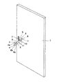
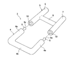
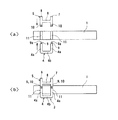
図1は、本発明の引き戸の施開錠構造の一実施形態における引き戸を示した斜視図である。図2は、引き戸に配設された錠を拡大して示した分解斜視図である。図3<a><b>は、それぞれ、錠の引き戸への取り付けを示した要部工程断面図である。 FIG. 1 is a perspective view showing a sliding door in an embodiment of the sliding door locking and unlocking structure of the present invention. FIG. 2 is an exploded perspective view showing an enlarged view of the lock disposed on the sliding door. FIGS. 3 <a> and <b> are cross-sectional views showing the main process of attaching the lock to the sliding door, respectively.
図1に示したように、引き戸1の引き手2のほぼ真下に、引き戸1の表裏両側からの施開錠が可能とされた錠3が取り付けられる。
As shown in FIG. 1, a
錠3は、図2に示したように、平面視略コ字状形状を有し、金属製、樹脂製などの丸棒、丸パイプなどから形成された操作部4と、平面視略H字状形状を有し、同様に金属製、樹脂製などの丸棒、丸パイプなどから形成された施開錠部5とを備えている。施開錠部5では、平行に離間配置された一方が施錠部6とされ、他方が開錠部7とされ、施錠部6および開錠部7は、長さ方向の略中央部から前端側にかけて両者に垂直に交わる連結部8によって一体に連結されている。
As shown in FIG. 2, the
操作部4と施開錠部5との横幅は略等しく、操作部4の左右両側に位置する腕部4aの後端と施開錠部5の前端、すなわち、施錠部6と開錠部7の両前端は対向配置可能であり、対向端部では、操作部4の腕部4a側に、先端に膨出部9aを有する突起9が腕部4aの後端から後方に向かって突設され、施開錠部5側に、施錠部6および開錠部7の両前端部に長さ方向にくぼんだ凹所10が形成されている。これらの突起9と凹所10とによって凹凸部が形成されている。突起9は凹所10内に嵌入可能であり、膨出部9aにおいて突起9は凹所10に密着し、このとき、操作部4の腕部4aの後端と施錠部6および開錠部7の両前端が当接し、操作部4と施開錠部5とが嵌着して錠3として一体となる。
The lateral widths of the
このような錠3を引き戸1に取り付けるために、図1に示したように、引き戸1の引き手2のほぼ真下に引き戸1を表裏に貫通する孔11が2つ、操作部4の腕部4aならびに施開錠部5の施錠部6および開錠部7に対応する位置に形成されている。
In order to attach such a
図3<a>に示したように、錠3を取り付ける際には、引き戸1の表面側に操作部4を配置し、裏面側に施開錠部5を配置する。このとき、施開錠部5の施錠部6は引き戸1の戸先側に配置する。そして、操作部4の2つの腕部4aをそれぞれ後端側から孔11に引き戸1の表面側より挿入するとともに、施開錠部5の施錠部6および開錠部7をそれぞれ前端側から孔11に引き戸1の裏面側より挿入する。
As shown in FIG. 3 <a>, when the
挿入後は、図3<b>に示したように、操作部4の腕部4aに突設された突起9が施錠部6および開錠部7の前端部に形成された凹所10に嵌まり込み、操作部4と施開錠部5とが嵌着一体化し、錠3が引き戸1に取り付けられる。取り付けられた錠3は、操作部4の両腕部4aの前端を横架し、連結する握り部4bが引き戸1の表面に接触し、また、施開錠部5に配設された連結部8が引き戸1の裏面に接触する範囲で引き戸1の表裏方向に移動可能となる。
After the insertion, as shown in FIG. 3 <b>, the
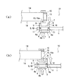
このようにして引き戸1に取り付けられた錠3は、図4<a><b>に示したように、引き戸1を閉めた状態において、建物の開口12の縁に設けられ、開口12の内周に設けられた開口枠13に接続され、壁面14から突出する額縁15の引き戸1側の額縁15aの開口12と反対側に位置する側端に施開錠部5の施錠部6が当接することにより施錠される。このように、錠3は、施錠のために建物側に何ら変更を加えず、開口12の縁に設けられる一方の額縁15aを利用しており、構造が簡略化されている。
The
開錠する際には、図4<a>に示したように、引き戸1の裏側から操作する場合は、施錠部6が額縁15aの開口12と反対側に位置する側端に当接している施錠状態において、施開錠部5の開口12側に位置する開錠部7を押し、引き戸1の裏面に近づけるように移動させる。この開錠部7の移動は施開錠部5全体の移動となり、操作部4を引き戸1の表面から離れるように移動させ、施錠部6の額縁15aの開口12の反対に位置する側端との当接が解除され、錠3は開錠される。引き戸1は、上下のレールに沿って開けることができる。
When unlocking, as shown in FIG. 4 <a>, when operating from the back side of the sliding
引き戸1の表側から操作する場合は、同様な施錠状態において、操作部4を握り部4bを掴むなどして引き、引き戸1から離れるように移動させる。この操作部4の移動によって施開錠部5が連動して引き戸1の裏面に近づくように移動し、施錠部6の額縁15aの開口12の反対に位置する側端との当接が解除され、錠3は開錠される。
When operating from the front side of the sliding
施錠する際には、図4<b>に示したように、引き戸1を閉めた状態において、引き戸1の表側から操作する場合は、操作部4を握り部4bを掴むなどして押し、引き戸1の表面に近づけるように移動させる。この操作部4の移動によって施開錠部5が連動して引き戸1の裏面から離れるように移動し、施開錠部5において施錠部6および開錠部7が額縁15aを挟んで引き戸1の裏側に突出し、施錠部6が額縁15aの開口12の反対に位置する側端と当接する。錠3の施錠状態となる。引き戸1は閉まった状態に保持される。
When locking, when operating from the front side of the sliding
引き戸1の裏側から操作する場合は、施開錠部5の開口12側に位置する開錠部7を引き、引き戸1の裏面から離れるように移動させる。この開錠部7の移動は施開錠部5全体の移動となり、操作部4を引き戸1の表面に近づけるように移動させ、施開錠部5において施錠部6および開錠部7が額縁15aを挟んで引き戸1の裏側に突出し、施錠部6が額縁15aの開口12の反対に位置する側端と当接する。錠3の施錠状態となる。
When operating from the back side of the sliding
このように、図1〜図4に示した引き戸の施開錠構造では、錠3は、引き戸1の表裏方向に移動可能で、裏面側に設けられた、額縁15aとの当接によって施錠状態にする施錠部6と、施錠部6の額縁15aとの当接を解除し、開錠状態にする開錠部7と、施錠部6および開錠部7に連結され、引き戸1の表面側に配置され、施錠部6および開錠部7を引き戸1の表裏方向に一体に移動させる操作部4とを備えた簡易な構造であるとともに、操作部4を引き戸1の表面に近づけるように移動させることによって、施錠部6および開錠部7が額縁15aを挟んで引き戸1から突出し、施錠部6が額縁15aに当接して施錠状態となり、施錠状態において、操作部4を引き戸1の表面から離れるように移動させるまたは開錠部7を引き戸1の裏面に近づけるように移動させることによって、施錠部6の額縁15aとの当接が解除され、開錠状態となり、施開錠を引き戸1の表裏両側から容易に行うことができる。
As described above, in the sliding door locking and unlocking structure shown in FIGS. 1 to 4, the
また、図1〜図4に示した引き戸の施開錠構造では、引き戸1の引き手2の付近に表裏を貫通する孔11を形成し、引き戸1の表面側から操作部4を孔11に挿入し、裏面側から施錠部6と開錠部7とが一体に連結された施開錠部5を挿入し、操作部4と施開錠部5との対向端部にそれぞれ設けられた突起9および凹所10から形成される凹凸部によって両者を嵌着し、錠3として一体化することができ、錠3の取り付けが容易であり、現場での施工が簡便となる。
In addition, in the sliding door locking and unlocking structure shown in FIGS. 1 to 4, a
なお、本発明の引き戸の施開錠構造では、操作部、施錠部および開錠部の形状、大きさおよび構造などについては特に制限はなく、建物の開口縁に設けられた額縁を利用して施錠可能であり、引き戸の表裏両側からの施開錠を可能とする限り、適宜なものを選択し、採用することができる。また、図1〜図4に示した引き戸の施開錠構造では、引き戸1の表面側に操作部4を配置し、裏面側に施開錠部5を配置したが、この配置は逆であってもよい。さらに、錠3の引き戸1への取り付け位置は、引き手2付近であればよく、引き手2の上方とすることもできる。
In addition, in the locking / unlocking structure of the sliding door of the present invention, there is no particular limitation on the shape, size, structure, etc. of the operation part, the locking part, and the unlocking part, and a frame provided at the opening edge of the building is used. As long as it can be locked and can be locked and unlocked from both sides of the sliding door, an appropriate one can be selected and employed. In the sliding door locking / unlocking structure shown in FIGS. 1 to 4, the
そして、本発明の引き戸の施開錠構造では、建物の開口に外付けで引き戸を開閉自在に取り付けるための構造には、上記特許文献1に記載された上レールおよび下レール、開口枠ならびに額縁を等しく採用することができる。
And in the locking / unlocking structure of the sliding door of the present invention, the structure for attaching the sliding door to the opening of the building so as to be openable and closable is provided in the upper rail and the lower rail, the opening frame and the frame described in
1 引き戸
2 引き手
3 錠
4 操作部
5 施開錠部
6 施錠部
7 開錠部
12 開口
13 開口枠
15a 額縁
DESCRIPTION OF
Claims (2)
錠は、引き戸の表裏方向に移動可能で、表裏いずれか一方側に設けられた、額縁との当接によって施錠状態にする施錠部と、施錠部の額縁との当接を解除し、開錠状態にする開錠部と、施錠部および開錠部に連結され、引き戸の他側に配置され、施錠部および開錠部を引き戸の表裏方向に一体に移動させる操作部とを備え、
操作部を引き戸に近づけるように移動させることによって、施錠部および開錠部が額縁を挟んで引き戸から突出し、施錠部が額縁に当接して施錠状態となり、施錠状態において、操作部を引き戸から離れるように移動させるまたは開錠部を引き戸に近づけるように移動させることによって、施錠部の額縁との当接が解除され、開錠状態となる
ことを特徴とする引き戸の施開錠構造。 A sliding door is attached to the opening of the building so that it can be opened and closed freely. The sliding door is attached to the opening edge of the building, connected to the opening frame provided on the inner periphery of the opening, and moved in the front and back direction of the sliding door to the frame protruding from the wall surface. The lock that is locked and unlocked when the locking part to be abutted and released is disposed near the sliding door puller, and the locking door can be unlocked from both the front and back sides of the sliding door. A lock structure,
The lock can be moved in the front and back direction of the sliding door, unlocked by releasing the abutment between the locking part provided on either the front or back side and brought into the locked state by abutting with the frame and the frame of the locking part An unlocking part to be in a state, and an operation part connected to the locking part and the unlocking part, arranged on the other side of the sliding door, and moving the locking part and the unlocking part integrally in the front and back direction of the sliding door,
By moving the operation part closer to the sliding door, the locking part and the unlocking part protrude from the sliding door across the frame, the locking part comes into contact with the frame and enters the locked state, and the operating part is separated from the sliding door in the locked state. The sliding door locking / unlocking structure is characterized in that the locking portion is released from contact with the frame by moving the locking portion or moving the unlocking portion closer to the sliding door.
Priority Applications (1)
| Application Number | Priority Date | Filing Date | Title |
|---|---|---|---|
| JP2007192626A JP4811368B2 (en) | 2007-07-24 | 2007-07-24 | Locking structure of sliding door |
Applications Claiming Priority (1)
| Application Number | Priority Date | Filing Date | Title |
|---|---|---|---|
| JP2007192626A JP4811368B2 (en) | 2007-07-24 | 2007-07-24 | Locking structure of sliding door |
Publications (2)
| Publication Number | Publication Date |
|---|---|
| JP2009030252A JP2009030252A (en) | 2009-02-12 |
| JP4811368B2 true JP4811368B2 (en) | 2011-11-09 |
Family
ID=40401054
Family Applications (1)
| Application Number | Title | Priority Date | Filing Date |
|---|---|---|---|
| JP2007192626A Expired - Fee Related JP4811368B2 (en) | 2007-07-24 | 2007-07-24 | Locking structure of sliding door |
Country Status (1)
| Country | Link |
|---|---|
| JP (1) | JP4811368B2 (en) |
Family Cites Families (2)
| Publication number | Priority date | Publication date | Assignee | Title |
|---|---|---|---|---|
| JP3591404B2 (en) * | 2000-01-26 | 2004-11-17 | 松下電工株式会社 | Locking structure of sliding door device |
| JP2006002348A (en) * | 2004-06-15 | 2006-01-05 | Koseisha:Kk | Locking device for sliding door |
-
2007
- 2007-07-24 JP JP2007192626A patent/JP4811368B2/en not_active Expired - Fee Related
Also Published As
| Publication number | Publication date |
|---|---|
| JP2009030252A (en) | 2009-02-12 |
Similar Documents
| Publication | Publication Date | Title |
|---|---|---|
| CN104662241A (en) | A completely recessed door handle provided with lock | |
| JP2020094410A (en) | Vehicle door structure | |
| JP5133273B2 (en) | Latch receiver and fitting | |
| JP4811368B2 (en) | Locking structure of sliding door | |
| TW202102094A (en) | Cable management assembly | |
| KR101383289B1 (en) | Inner forced locking assembly of push-pull doorlock | |
| JP6853548B2 (en) | Doors and door devices | |
| JP5817495B2 (en) | Control lever for seat slide device | |
| JP5942104B2 (en) | Joinery latch lock | |
| JP3993913B2 (en) | Push-pull tablet | |
| JP4274882B2 (en) | Opening and closing door stopper | |
| JP2007186934A (en) | Door locking device | |
| WO2012172734A1 (en) | Sliding door opening assistance device | |
| JP4594682B2 (en) | Shoji auxiliary locking device | |
| JP3503050B2 (en) | Latch mechanism of double door system | |
| JP3134039U (en) | Double door device | |
| JPH09322833A (en) | Latch device for furniture | |
| JP2005036403A (en) | Flat lock mechanism | |
| JP7589990B2 (en) | Door opening and closing device | |
| KR101383622B1 (en) | Safety locking assembly for push-pull doorlock | |
| JP6384855B2 (en) | Sliding door device and safety stopper | |
| JP4593578B2 (en) | Handle device for hinged door and hinged door having the same | |
| KR200295523Y1 (en) | Fastenning device of cavinet | |
| KR101690870B1 (en) | Auto locking device for window | |
| JP3884933B2 (en) | Locking device for sliding door |
Legal Events
| Date | Code | Title | Description |
|---|---|---|---|
| A621 | Written request for application examination |
Free format text: JAPANESE INTERMEDIATE CODE: A621 Effective date: 20090423 |
|
| A977 | Report on retrieval |
Free format text: JAPANESE INTERMEDIATE CODE: A971007 Effective date: 20110715 |
|
| TRDD | Decision of grant or rejection written | ||
| A01 | Written decision to grant a patent or to grant a registration (utility model) |
Free format text: JAPANESE INTERMEDIATE CODE: A01 Effective date: 20110726 |
|
| A01 | Written decision to grant a patent or to grant a registration (utility model) |
Free format text: JAPANESE INTERMEDIATE CODE: A01 |
|
| A61 | First payment of annual fees (during grant procedure) |
Free format text: JAPANESE INTERMEDIATE CODE: A61 Effective date: 20110808 |
|
| R150 | Certificate of patent or registration of utility model |
Free format text: JAPANESE INTERMEDIATE CODE: R150 |
|
| FPAY | Renewal fee payment (event date is renewal date of database) |
Free format text: PAYMENT UNTIL: 20140902 Year of fee payment: 3 |
|
| LAPS | Cancellation because of no payment of annual fees |