JP4810585B2 - Calculator that supports remote scan - Google Patents
Calculator that supports remote scan Download PDFInfo
- Publication number
- JP4810585B2 JP4810585B2 JP2009114130A JP2009114130A JP4810585B2 JP 4810585 B2 JP4810585 B2 JP 4810585B2 JP 2009114130 A JP2009114130 A JP 2009114130A JP 2009114130 A JP2009114130 A JP 2009114130A JP 4810585 B2 JP4810585 B2 JP 4810585B2
- Authority
- JP
- Japan
- Prior art keywords
- storage
- path
- host
- scan
- host computer
- Prior art date
- Legal status (The legal status is an assumption and is not a legal conclusion. Google has not performed a legal analysis and makes no representation as to the accuracy of the status listed.)
- Expired - Fee Related
Links
Images


Classifications
-
- H—ELECTRICITY
- H04—ELECTRIC COMMUNICATION TECHNIQUE
- H04L—TRANSMISSION OF DIGITAL INFORMATION, e.g. TELEGRAPHIC COMMUNICATION
- H04L67/00—Network arrangements or protocols for supporting network services or applications
- H04L67/01—Protocols
- H04L67/10—Protocols in which an application is distributed across nodes in the network
- H04L67/1097—Protocols in which an application is distributed across nodes in the network for distributed storage of data in networks, e.g. transport arrangements for network file system [NFS], storage area networks [SAN] or network attached storage [NAS]
-
- H—ELECTRICITY
- H04—ELECTRIC COMMUNICATION TECHNIQUE
- H04L—TRANSMISSION OF DIGITAL INFORMATION, e.g. TELEGRAPHIC COMMUNICATION
- H04L45/00—Routing or path finding of packets in data switching networks
- H04L45/12—Shortest path evaluation
- H04L45/124—Shortest path evaluation using a combination of metrics
Landscapes
- Engineering & Computer Science (AREA)
- Computer Networks & Wireless Communication (AREA)
- Signal Processing (AREA)
- Information Retrieval, Db Structures And Fs Structures Therefor (AREA)
Abstract
Description
本発明は、直列に接続された複数のストレージシステムのいずれかからスキャン対象の論理ボリュームに関する情報を取得する技術に関する。 The present invention relates to a technique for acquiring information related to a scan target logical volume from any of a plurality of storage systems connected in series.
直列に接続された複数のストレージシステムのいずれかからスキャン対象の論理ボリュームに関する情報を取得する技術として、例えば、特許文献1及び2に開示の技術がある。
As a technique for acquiring information relating to a logical volume to be scanned from any of a plurality of storage systems connected in series, for example, there are techniques disclosed in
以下の説明では、少なくとも一つのホスト計算機に接続されているストレージシステムを「ローカルストレージ」と呼び、いずれのホスト計算機にも接続されていないストレージシステムを「リモートストレージ」と呼ぶ。また、ホスト計算機とストレージシステムを「ノード」と総称することがある。 In the following description, a storage system connected to at least one host computer is called “local storage”, and a storage system not connected to any host computer is called “remote storage”. In addition, the host computer and the storage system may be collectively referred to as “node”.
この種の技術では、一般的に、複数のストレージシステムには、二以上のローカルストレージと一以上のリモートストレージが含まれている。スキャン対象の論理ボリュームに関する情報(以下、スキャン結果情報)を取得するためのスキャンコマンドは、いずれかのホスト計算機から発行される。 In this type of technology, generally, a plurality of storage systems include two or more local storages and one or more remote storages. A scan command for acquiring information related to the scan target logical volume (hereinafter referred to as scan result information) is issued from one of the host computers.
スキャン対象のストレージシステムが、そのホスト計算機に接続されているローカルストレージであれば、そのローカルストレージからそのホスト計算機にスキャン結果情報が送信される。 If the storage system to be scanned is a local storage connected to the host computer, scan result information is transmitted from the local storage to the host computer.
一方、スキャン対象のストレージシステムが、いずれかのリモートストレージであれば、スキャンコマンドは、そのスキャンコマンドを受けたローカルストレージから、一以上のストレージシステムを順次に経由して、スキャン対象のリモートストレージに届く。そして、そのリモートストレージから、スキャン結果情報が送信される。送信されたスキャン結果情報は、上記一以上のストレージシステムを逆の順序に経由し、ローカルストレージを通じて、スキャンコマンドの発行元のホスト計算機に届く。以下、リモートストレージから上記スキャン結果情報を取得することを「リモートスキャン」と言う。 On the other hand, if the storage system to be scanned is one of the remote storages, the scan command is sent from the local storage that received the scan command to the remote storage to be scanned through one or more storage systems in sequence. reach. Then, scan result information is transmitted from the remote storage. The transmitted scan result information passes through the one or more storage systems in the reverse order and reaches the host computer that issued the scan command through the local storage. Hereinafter, acquiring the scan result information from the remote storage is referred to as “remote scan”.
各ローカルストレージが、直接的に或いは少なくとも一つのストレージシステムを介して、スキャン対象のリモートストレージに接続されているケースがある。このケースでは、二以上のホスト計算機のいずれからリモートスキャンのコマンドを発行しても、スキャン対象のリモートストレージからスキャン結果情報を取得することができる。 In some cases, each local storage is connected to a remote storage to be scanned, either directly or via at least one storage system. In this case, even if a remote scan command is issued from any of two or more host computers, the scan result information can be acquired from the remote storage to be scanned.
このケースでは、どのホスト計算機からリモートスキャンのコマンドを発行するかを、ユーザが選択する。ユーザは、通常、ノード間の接続構成(すなわち、どのホスト計算機がどのストレージシステムに接続されているかや、どのストレージシステムがどのストレージシステムに接続されているか)を知らない。このため、リモートスキャンのコマンドを発行するのに最適なホスト計算機を選択することが難しい。 In this case, the user selects from which host computer the remote scan command is issued. The user usually does not know the connection configuration between nodes (that is, which host computer is connected to which storage system and which storage system is connected to which storage system). For this reason, it is difficult to select an optimal host computer for issuing a remote scan command.
そこで、本発明の目的は、リモートスキャンのコマンドを発行するのに最適なホスト計算機を選択できる確率を高めることにある。 Accordingly, an object of the present invention is to increase the probability that an optimal host computer can be selected for issuing a remote scan command.
複数のホスト計算機が接続されている通信ネットワークに接続されている計算機が、経路調査処理と、スキャン処理とを実行する。その計算機は、複数のホスト計算機のうちのいずれかのであっても良い。また、その計算機は、一つの計算機であっても良いし複数の計算機で構成されていても良い。 A computer connected to a communication network to which a plurality of host computers are connected executes a route investigation process and a scan process. The computer may be any one of a plurality of host computers. Further, the computer may be a single computer or a plurality of computers.
前述した経路調査処理は、
(a1)ホスト計算機とローカルストレージとを接続するパスであるホストパスに関するホスト/ストレージ接続情報を取得する処理と、
(a2)ストレージシステムとストレージシステムとを接続するパスであるストレージパスに関するストレージ/ストレージ接続情報を各ホスト計算機を通じて取得する処理と、
(a3)ホスト/ストレージ接続情報とストレージ/ストレージ接続情報とを基に経路管理情報を生成し、生成した経路管理情報を保存する処理と
を含む。経路管理情報は、複数の経路に関する情報である。一つの経路は、直列に接続された二以上のノードとノード間のパスとで構成されている。二以上のノードのうちのスタートノードが、いずれかのホスト計算機であり、その二以上のノードうちの他のノードが、いずれかのストレージシステムである。
The route investigation process described above is
(A1) processing for acquiring host / storage connection information relating to a host path that is a path connecting the host computer and the local storage;
(A2) processing for acquiring storage / storage connection information related to a storage path, which is a path connecting the storage system and the storage system, through each host computer;
(A3) processing for generating path management information based on the host / storage connection information and the storage / storage connection information, and storing the generated path management information. The route management information is information regarding a plurality of routes. One path is composed of two or more nodes connected in series and a path between the nodes. The start node of the two or more nodes is any host computer, and the other node of the two or more nodes is any storage system.
前述したスキャン処理は、
(b1)一以上のストレージカスケードを構成する複数のストレージシステムのうちのスキャン対象のストレージシステムをエンドノードとする複数の経路を経路管理情報から特定する処理と、
(b2)スキャン対象のストレージシステムがいずれかのリモートストレージであることが上記(b1)の処理においてわかった場合に、経路管理情報を基に、リモートスキャンを実行するホスト計算機として、上記複数の経路のうちの最適な経路のスタートノードであるホスト計算機を選択する処理と
を含む。計算機は、スキャン処理において、上記(b2)で選択されたホスト計算機にリモートスキャンを命じても良い。
The scan process described above
(B1) a process of identifying a plurality of paths having a scan target storage system as an end node among a plurality of storage systems constituting one or more storage cascades from path management information;
(B2) When the storage system to be scanned is one of the remote storages in the process (b1), the plurality of paths as the host computer that executes the remote scan based on the path management information And selecting a host computer that is the start node of the optimal route. The computer may instruct the host computer selected in (b2) to perform a remote scan in the scan process.
上記(b2)において、計算機は、最適な経路のスタートノードであるホスト計算機を表す情報を表示することなくそのホスト計算機を選択しても良いし、その情報を表示し、ユーザからそのホスト計算機の指定を受け付けたことに応答して、そのホスト計算機を選択しても良い。 In the above (b2), the computer may select the host computer without displaying the information indicating the host computer that is the start node of the optimum route, or display the information, and the user can select the host computer. The host computer may be selected in response to accepting the designation.
図1は、本発明の一実施形態に係る計算機システムの概要を示す。 FIG. 1 shows an overview of a computer system according to an embodiment of the present invention.
2つのホスト計算機111がある。以下、それら2つのホスト計算機111を、それぞれ、「ホスト1」及び「ホスト2」と称する。また、それらを特に区別しない場合には「ホスト」と総称することがある。
There are two
ホスト1及び2に、管理サーバ101が接続されている。ただし、管理サーバ101の機能がホスト1及び2のいずれかに設けられている場合には、管理サーバ101は必ずしも無くても良い。
A
1つのストレージカスケードがある。そのストレージカスケードは、直列に接続された4つのストレージシステム121で構成されている。以下、それら4つのストレージシステムを、それぞれ、「ストレージ1」、「ストレージ2」、「ストレージ3」及び「ストレージ4」と称する。また、それらを特に区別しない場合には「ストレージ」と総称することがある。また、ホストとストレージを「ノード」と総称することがある。
There is one storage cascade. The storage cascade is composed of four
ストレージ1〜4のうち、ストレージ1にホスト1がホストパスP31で直結されており、ストレージ4にホスト2がホストパスP32で直結されている。このため、ストレージ1及び4が、それぞれ、ローカルストレージであり、ストレージ2及び3が、それぞれ、リモートストレージである。なお、本実施形態において、「直結されている」とは、いずれのノード(ホスト又はストレージ)を介することなく接続されていることを意味する。また、「ホストパス」とは、ホストとストレージとを接続するパスである。
Among the
ストレージ同士を接続するパスであるストレージパスの向きが予め定義されている。図1によれば、ストレージ間毎に、ストレージ1からストレージ4への方向(第一の方向)のパスである第一のストレージパスP11、P12又はP13と、ストレージ4からストレージ1への方向(第二の方向)のパスである第二のストレージパスP23、P22又はP21とが予め定義されている。スキャンコマンドは、ストレージパスの向きに沿って転送される。スキャンコマンドに限らず、他種のコマンドも、ストレージパスの向きに沿って転送される。たとえば、ホスト1が、ストレージ2内の論ボリュームを指定したI/Oコマンド(ライトコマンド又はリードコマンド)を送信した場合、そのI/Oコマンドは、ストレージ1及び第一のストレージパス(P11)を介して、ストレージ2に転送される。
The direction of the storage path, which is a path connecting the storages, is defined in advance. According to FIG. 1, for each storage, a first storage path P11, P12 or P13, which is a path in the direction from the
各ホストは、そのホストとローカルストレージとを接続するホストパスに関するホスト/ストレージ接続情報を保持している。例えば、ホスト1が保持するホスト/ストレージ接続情報は、ホスト1に直結されているストレージ1を表す情報を含んでいる。ホスト/ストレージ接続情報は、具体的には、例えば、後述するホストパステーブル210である(図2、図3B参照)。
Each host holds host / storage connection information regarding a host path connecting the host and the local storage. For example, the host / storage connection information held by the
各ストレージは、ストレージ同士を接続するストレージパスに関するストレージ/ストレージ接続情報を保持している。例えば、ストレージ2が保持するストレージ/ストレージ接続情報は、ストレージ2に直結されているストレージ1及び3を表す情報を含んでいる。ストレージ/ストレージ接続情報は、具体的には、例えば、後述するストレージパステーブル242である(図2、図3A参照)。
Each storage holds storage / storage connection information regarding storage paths connecting the storages. For example, the storage / storage connection information held by the
本実施形態では、管理サーバ101が、ホスト/ストレージ接続情報及びストレージ/ストレージ接続情報を取得し、それらの情報を基に、経路管理情報を生成する。経路管理情報が、存在する全ての経路に関する情報である。従って、どのホストがどのストレージに接続されていて、どのストレージがどのストレージに接続されているかを把握することができる。なお、一つの経路は、直列に接続された二以上のノードとノード間のパスとで構成されており、その二以上のノードのうちのスタートノードが、いずれかのホストであり、その二以上のノードうちの他のノードが、いずれかのストレージである。例えば、ストレージ3をエンドノードとする経路として、2つの経路がある。1つ目の経路は、第1の向きの経路、すなわち、ホスト1、ホストパスP31、ストレージ1、第一のストレージパスP11、ストレージ2及び第一のストレージパスP12を含んだ経路である。2つ目の経路は、第2の向きの経路、すなわち、ホスト2、ホストパスP32、ストレージ4及び第二のストレージパスP23を含んだ経路である。
In the present embodiment, the
管理サーバ101は、各ホストを通じて全てのストレージからストレージ/ストレージ情報を取得する。その際、第一の方向と第二の方向の両方の方向に沿ってストレージ/ストレージ情報が取得される。具体的には、例えば、管理サーバ101は、ホスト1を通じてストレージ1からストレージ/ストレージ情報を取得し、次に、その情報から特定されるストレージ2からホスト1及びストレージ1を通じてストレージ/ストレージ情報を取得し、次に、その情報から特定されるストレージ3からホスト1、ストレージ1及びストレージ2を通じてストレージ/ストレージ情報を収集し、最後に、その情報から特定されるストレージ4からホスト1、ストレージ1、ストレージ2及びストレージ3を通じてストレージ/ストレージ情報を取得する。同様の方法で、管理サーバ101は、ホスト2を通じてストレージ4からストレージ/ストレージ情報を取得し、その後、ストレージ3、ストレージ2及びストレージ1の順で、ホスト2を通じて、ストレージ/ストレージ情報を取得する。
The
経路管理情報は、例えば、後述の経路テーブル217である(図2、図6参照)。管理サーバ101は、経路管理情報を基に、スキャン対象のリモートストレージをエンドノードとする複数の経路のうちの最適な経路を特定し、最適な経路のスタートノードのホストを選択する。そして、管理サーバ101は、そのホストにリモートスキャン(スキャン対象のリモートストレージからスキャン対象の論理ボリュームに関する情報を取得すること)を実行させる。例えば、スキャン対象のリモートストレージがストレージ3の場合、ストレージ3をエンドノードとする経路は前述した2つの経路があるが、その2つの経路のうち、第2の向きの経路の距離の方が第1の向きの経路の距離よりも短い。このため、管理サーバ101は、第2の向きの経路のスタートノードであるホスト2を選択し、ホスト2にリモートスキャンを実行させる。
The route management information is, for example, a route table 217 described later (see FIGS. 2 and 6). Based on the route management information, the
なお、「経路の距離」とは、ここでは、スタートノードからエンドノードに至るまでにノード間をホップすることになる数(ホップ数)である。ホップ数が多ければ距離が長いということであり、ホップ数が少なければ距離が短いということである。ホップ数は、スタートノードとエンドノードとの間に存在するノード(以下、中間ノード)の数が少なければ少なくなり、中間ノードの数が多くなれば多くなる。ホップ数は、中間ノードの数+1である。 Here, the “path distance” is the number of hops between the nodes from the start node to the end node (the number of hops). If the number of hops is large, the distance is long. If the number of hops is small, the distance is short. The number of hops decreases as the number of nodes (hereinafter, intermediate nodes) existing between the start node and the end node decreases, and increases as the number of intermediate nodes increases. The number of hops is the number of intermediate nodes + 1.
図1に示した構成例ではあり得ないが、別の構成例では、スキャン対象のリモートストレージをエンドノードとする複数の経路に、距離が同じ経路が二つ以上含まれていることがあり得る。この場合、管理サーバ101は、それら二以上の経路のうち、負荷が最小の経路を特定し、負荷が最小の経路のスタートノードのホストを選択する。経路毎の負荷は、後述するように、単位時間(例えば1秒間)当たりの回線帯域及びデータ量を基に算出される。
Although not the configuration example illustrated in FIG. 1, in another configuration example, a plurality of routes having the remote storage to be scanned as an end node may include two or more routes having the same distance. . In this case, the
さらに、負荷が最小の経路が二つ以上存在する場合には、管理サーバ101は、二以上の負荷最小経路に対応した二以上のホストのうち、負荷が最小のホストを選択する。ホストの負荷は、ホストのリソースの動作状態を基に特定される。リソースの動作状態としては、例えば、CPUクロックサイクル時間及びメモリ使用率などを採用することができるが、本実施形態では、CPUクロックサイクル時間が採用される。
Further, when there are two or more paths with the minimum load, the
本実施形態では、二以上の負荷最小経路がある場合、ホストの負荷に基づいてホストが選択されるが、それに代えて又は加えて、他のノードの負荷(例えばローカルストレージの負荷)も考慮されても良い。例えば、ホストとそのホストに直結されているローカルノードとのセット(ホスト/ローカルストレージセット)毎に、負荷が特定され、最も負荷の小さいホスト/ローカルストレージセットに属するホストが選択されても良い。 In this embodiment, when there are two or more minimum load paths, the host is selected based on the load of the host, but instead of or in addition, the load of other nodes (for example, the load of local storage) is also considered. May be. For example, a load may be specified for each set (host / local storage set) of a host and a local node directly connected to the host, and a host belonging to the host / local storage set having the smallest load may be selected.
また、本実施形態では、経路の距離、経路の負荷、及び、ノードの負荷のうち、経路の距離が最優先され、次に、経路の負荷が優先されるが、優先順位はそれに限らなくても良い(たとえば、経路の負荷が最優先されても良い)。或いは、それら三つの要素(経路の距離、経路の負荷、及び、ノードの負荷)のうちの少なくとも二つが常に参酌されても良い。具体的には、スキャン対象のリモートストレージをエンドノードとする複数の経路について、下記の三つの要素:
(X1)経路の距離の差;
(X2)経路の負荷の差;
(X3)ノード(例えばホスト)の負荷の差、
のうちの少なくとも二つの要素が常に参酌されても良い。たとえば、第一の経路の方が第二の経路より短いが、それらの距離の差が所定値未満であって、第一の経路の負荷の方が第二の負荷よりも所定値以上に大きい場合には、第二の経路が選択されても良い。
In this embodiment, the route distance has the highest priority among the route distance, the route load, and the node load, and then the route load has priority, but the priority order is not limited thereto. (For example, the route load may be given the highest priority). Alternatively, at least two of these three elements (path distance, path load, and node load) may always be considered. Specifically, the following three elements for multiple paths that use the remote storage to be scanned as an end node:
(X1) route distance difference;
(X2) path load difference;
(X3) load difference of nodes (for example, hosts),
At least two of the elements may always be considered. For example, the first route is shorter than the second route, but the distance difference between them is less than a predetermined value, and the load on the first route is greater than the second load by a predetermined value or more. In some cases, the second route may be selected.
さて、リモートスキャンの実行が命じられたホストは、リモートスキャンのコマンドを発行する。そのリモートスキャンコマンドに応答して、スキャン対象のリモートストレージから、スキャン対象の論理ボリュームに関するスキャン結果情報を受ける。管理サーバ101は、スキャン対象のリモートストレージをエンドノードとする全ての経路のスタートノードのホスト(但し、そのリモートスキャンコマンドの発行元のホストを除く)を、経路管理情報を基に特定する。そして、管理サーバ101は、特定されたホストに、スキャン結果情報を送信する。例えば、図1に示した構成例によれば、いずれのストレージがスキャン対象となっても、ホスト1又は2のうちのいずれかにスキャン結果情報が送信されることになる。別の構成例、例えば、図16に示した構成例において、スキャン対象のストレージ12にホスト11からリモートスキャンコマンドが送信された場合、管理サーバ101は、ホスト12にスキャン結果情報を送信するが、他のホスト13にはその情報を送信しない。なぜなら、ストレージ12をエンドノードとする経路はホスト1以外ではホスト2のみであるからである。なお、「スキャン結果情報を送信する」とは、ストレージから取得されたスキャン結果情報それ自体を送信するのであっても良いし、そのスキャン結果情報を基に更新されたシステム構成情報(どのストレージシステムにどの論理ボリュームが存在するかを表す情報、例えば後述の構成ファイル209(図2参照))を送信するのであっても良い。なお、スキャン結果情報を他のホストに送信する理由は、或るホストが使用不可能になった場合に、他のホストにもスキャン結果情報を送信しておかないと、他のホストで業務を継続することができないことにある(つまりディザスタリカバリを考慮したことにある)。
Now, the host that is instructed to execute the remote scan issues a remote scan command. In response to the remote scan command, scan result information regarding the scan target logical volume is received from the scan target remote storage. The
以上が、本実施形態の概要である。以下、本実施形態を詳細に説明する。 The above is the outline of the present embodiment. Hereinafter, this embodiment will be described in detail.
図2は、本発明の一実施形態に係る計算機システムの構成を示す。 FIG. 2 shows a configuration of a computer system according to an embodiment of the present invention.
ホスト1及び2と管理サーバ101は、IP(Internet Protocol)ネットワーク115に接続されている。ストレージ1〜4が、SAN(Storage Area Network)225に接続されている。IPネットワーク115及びSAN225のうちの少なくとも1つが他種のネットワークであっても良い。また、ホスト1及び2、管理サーバ101及びストレージ1〜4が共通のネットワークに接続されていても良い。例えば、ホスト1及び2がSAN225に接続されても良い。
The
ホスト1及び2について、ホスト1を代表的に例に採り説明する。
The
ホスト1は、IF202と、記憶資源と、それらに接続されたCPU201とを有する。記憶資源は、例えば、メモリ203とディスク207である。
The
IF202は、IPネットワーク115を介した通信を行うためのネットワークインターフェイスである。
The
メモリ203は、CPU201に実行されるコンピュータプログラム、例えば、オペレーティングシステム(図示せず)、AP(アプリケーションプログラム)204及びレプリケーション管理ソフト206を記憶する。
The
ディスク207は、ディスク型の記憶装置、例えばハードディスクである。ディスク207は、構成ファイル209及びホストパステーブル210を記憶する。
The
管理サーバ101は、IF302と、記憶資源と、それらに接続されたCPU301とを有する。記憶資源は、例えば、メモリ303とディスク307である。
The
IF302は、IPネットワーク115を介した通信を行うためのネットワークインターフェイスである。
The
メモリ303は、CPU301に実行されるコンピュータプログラム、例えば、オペレーティングシステム(図示せず)、及び統合レプリケーション管理ソフト211を記憶する。また、メモリ303は、配列(W1)212と、配列(W2)213とを記憶する。
The
ディスク307は、ディスク型の記憶装置、例えばハードディスクである。ディスク307は、ホストパス管理テーブル214、ストレージパス管理テーブル215、ストレージテーブル216、経路テーブル217及び構成ファイル209を記憶する。構成ファイル209は、ホスト1及び2が有する構成ファイル209と同じである。構成ファイル209は、スキャン結果情報を基に作成又は更新されるファイルであり、例えば、どのストレージがどの論理ボリュームを有するかを表す情報が記述されている。
The
ストレージ1〜4について、ストレージ1を代表的に例に採り説明する。
The
ストレージ1は、コントローラ(以下、CTL)241と、複数の論理ボリューム(以下、VOL)とを有する。
The
CTL241は、複数のポート、CPU及びメモリを有する。CTL241は、ホストから直接或いは他のストレージを介して受信したI/Oコマンドで指定されているVOLにアクセスする。CTL241内のメモリは、ストレージパステーブル242を記憶する。
The
各VOLは、仮想的なVOLと実体的なVOLのいずれかである。実体的なVOLは、RAID(Redundant Array of Independent (or Inexpensive) Disks)グループを基に形成されている。RAIDグループは、所定のRAIDレベルでデータを記憶する。RAIDグループは、複数の物理記憶デバイス(例えばハードディスク或いはフラッシュメモリ)で構成されている。 Each VOL is either a virtual VOL or a substantial VOL. The substantial VOL is formed based on a RAID (Redundant Array of Independent (or Inexpensive) Disks) group. The RAID group stores data at a predetermined RAID level. The RAID group is composed of a plurality of physical storage devices (for example, hard disks or flash memories).
複数のVOLは、ホストVOLと、コマンドデバイス(図2では「CD」略記)とを含む。 The plurality of VOLs include a host VOL and a command device (abbreviated as “CD” in FIG. 2).
ホストVOLは、ホストからのI/Oコマンドで指定され得るVOLである。 The host VOL is a VOL that can be specified by an I / O command from the host.
コマンドデバイスは、コマンド制御用のVOLである。コマンドデバイスには、種々のコマンド、例えば、そのコマンドデバイスを有するストレージ内の他のVOLが指定されたコマンドや、他のストレージに対するコマンドが格納される。本実施形態では、一つのストレージに、第1の方向(ストレージ1からストレージ4への向き)用のコマンドデバイスと、第2の方向(ストレージ4からストレージ1への向き)用のコマンドデバイスとが設けられている。図2の例で言えば、ストレージ1〜4において、第1の方向用のコマンドデバイスは、コマンドデバイス1〜4であり、第2の方向用のコマンドデバイスは、コマンドデバイス5〜8である。
The command device is a VOL for command control. The command device stores various commands, for example, commands in which other VOLs in the storage having the command device are designated, and commands for other storages. In this embodiment, a command device for the first direction (direction from the
各ストレージにおいて、コマンドデバイスとコマンドデバイスとの間の物理パス及び論理パスが設定済みである。 In each storage, a physical path and a logical path between the command device and the command device have been set.
「論理パス」とは、図17に示すように、1又は複数の物理パス1701上に仮想的に確立される通信路1702のことである。1つの論理パスは最大8つの物理パスを有することができる。「物理パス」は、回線と同義語である。物理パスは、送信側ストレージ内のCU(Control Unit)に関連付けられたポート(イニシエータポート)から受信側ストレージ内のCUに関連付けられたポート(ターゲットポート)へのパスである(それらのポート間は例えばファイバチャネルケーブルで接続されている)。「CU」は、VOLに対応付けられている要素であり、CUに対応付けられているVOLは、複数の論理記憶デバイスの集合である。
A “logical path” is a
コマンドデバイス間の論理パスは、コマンドデバイス専用の論理パス、又は、コピー用の論理パスである。コマンドデバイス間の通信は単方向のため、2つのストレージ間で両方向の通信をするために、コマンドデバイスと論理パスがそれぞれ2つ設定されている。図2において、論理パス及びその向きは、コマンドデバイス間に示されている矢印及びその向きである。 The logical path between command devices is a logical path dedicated to the command device or a logical path for copying. Since communication between command devices is unidirectional, two command devices and two logical paths are set in order to perform bidirectional communication between two storages. In FIG. 2, the logical path and its direction are the arrows and their directions shown between the command devices.
本実施形態では、コマンドデバイス間の物理パス(回線)の帯域及び単位時間当りのデータ量を基に、ストレージパス(論理パス)の負荷が決定される。もし、1つの論理パスが複数の物理パスを有する場合には、ストレージパスの負荷の算出には、それら複数の物理パスのうちの少なくとも1つの物理パスの帯域及び単位時間当りのデータ量が考慮される。例えば、それら複数の物理パスの帯域及びデータ量の平均値が用いられても良いし、データ量÷帯域の値が最も小さい物理パス(つまり負荷の最も小さい物理パス)の帯域及びデータ量が用いられても良い。 In this embodiment, the load on the storage path (logical path) is determined based on the bandwidth of the physical path (line) between command devices and the amount of data per unit time. If one logical path has a plurality of physical paths, the storage path load is calculated by considering the bandwidth of at least one of the plurality of physical paths and the data amount per unit time. Is done. For example, the average value of the bandwidth and data amount of the plurality of physical paths may be used, or the bandwidth and data amount of the physical path having the smallest value of data amount / bandwidth (that is, the physical path having the smallest load) is used. May be.
ホストが有するレプリケーション管理ソフト206は、下記の機能:
(1)コピー操作(VOLペアの作成や、VOLペアペアの状態変更を行う機能);
(2)コピーグループ操作(複数のVOLペアをグループ化し、グループ単位で操作を実行する機能);
(3)ボリュームスキャン(ストレージからVOLに関する情報を取得する機能);
(4)リモートストレージ制御(リモートストレージを制御(操作)する機能);
(5)論理パス制御(ストレージパスを確立・削除する機能);
を有する。
The
(1) Copy operation (function to create a VOL pair and change the status of a VOL pair);
(2) Copy group operation (a function for grouping a plurality of VOL pairs and executing the operation in group units);
(3) Volume scan (function to acquire information about VOL from storage);
(4) Remote storage control (function to control (operate) remote storage);
(5) Logical path control (function to establish / delete storage path);
Have
ボリュームスキャンは、例えば、コピーグループ定義のために必要となる。スキャン結果情報は、構成ファイル209に格納される。構成ファイル209に格納されたVOL情報(どのストレージがどのVOLを有するか)を基に、VOLペアやVOLペアグループが作成される。ボリュームスキャンとしては、ローカルスキャンとリモートスキャンの2種類がある。
The volume scan is necessary for defining a copy group, for example. Scan result information is stored in the
ローカルスキャンは、スキャン対象がローカルストレージの場合のボリュームスキャンである。つまり、ローカルストレージからスキャン結果情報が取得される。 The local scan is a volume scan when the scan target is a local storage. That is, scan result information is acquired from the local storage.
リモートスキャンは、スキャン対象がリモートストレージの場合のボリュームスキャンである。リモートスキャンのためには、リモートスキャンコマンドの転送のために、前述したストレージパスの設定が必要である。リモートスキャンの操作のために、ユーザは、例えば、リモートストレージのシリアル番号、スキャンするVOLの範囲(例えば、VOL番号の範囲)、及びルートリストを入力する。ルートリストとは、リモートスキャンコマンドの転送順路であり、どのストレージをどの順番で経由するかを表す。例えば、14001→14002→14003というルートリスト(シリアル番号のリスト)は、ストレージ1→ストレージ2→ストレージ3という転送順路を意味する。このため、そのルートリストを含んだリモートスキャンコマンドは、ローカルストレージ1、リモートストレージ2を経由して、リモートストレージ3に届く。具体的には、そのリモートスキャンコマンドは、以下の順で処理される。
The remote scan is a volume scan when the scan target is a remote storage. For remote scan, the storage path setting described above is required for transfer of the remote scan command. For the remote scan operation, the user inputs, for example, a remote storage serial number, a VOL range to be scanned (for example, a VOL number range), and a route list. The route list is a transfer path of the remote scan command and represents which storage is passed in which order. For example, a route list (serial number list) of 14001 → 14002 → 14003 means a transfer route of
ローカルストレージ1内のCTL1が、ホスト1からリモートスキャンコマンドを受信し、そのリモートスキャンコマンドをコマンドデバイス1に格納する。CTL1は、そのリモートスキャンコマンド内のルートリストに従い、そのリモートスキャンコマンドを、コマンドデバイス1からストレージパスP11を経由してリモートストレージ2に転送する。リモートストレージ2内のCTL2が、ストレージパスP11経由でリモートスキャンコマンドを受信し、そのコマンドをコマンドデバイス2に格納する。CTL2は、そのリモートスキャンコマンド内のルートリストに従い、そのリモートスキャンコマンドを、コマンドデバイス2からストレージパスP12を経由してリモートストレージ3に転送する。リモートストレージ3内のCTL3が、ストレージパスP12経由でリモートスキャンコマンドを受信し、そのコマンドをコマンドデバイス3に格納する。
The
CTL3は、コマンドデバイス3内のリモートスキャンコマンドを参照し、そのコマンドで指定されているVOL範囲に属するVOLに関する情報を取得し、その情報を含んだスキャン結果情報(ボリューム情報)を送信する。そのスキャン結果情報は、リモートスキャンコマンドの転送順序とは逆の順序でストレージを経由してホスト1に到達する。具体的には、例えば、スキャン結果情報は、ストレージパスP22、ストレージ2、ストレージパスP21及びローカルストレージ1を経由して、ホスト1に届く。ホスト1内のレプリケーション管理ソフト206は、そのスキャン結果情報を構成ファイル209に格納する。また、そのレプリケーション管理ソフト206は、スキャン結果情報(例えば、更新後の構成ファイル209)を、管理サーバ101に送信する。管理サーバ101内の統合レプリケーション管理ソフト211が、そのスキャン結果情報を、ホスト2に送信する。ホスト2内のレプリケーション管理ソフト206は、そのスキャン結果情報を保存する(例えば、構成ファイル209を作成、更新又は保存する)。
The
さて、以下、ストレージ、ホスト及び管理サーバが有するテーブルを詳細に説明する。 Now, the tables of the storage, host, and management server will be described in detail.
図3Aは、ストレージが有するストレージパステーブル242を示す。 FIG. 3A shows a storage path table 242 included in the storage.
ストレージパステーブル242は、ストレージパスに関する情報が記述されているテーブルである。このテーブル242には、このテーブル242を有するストレージを送信側ストレージとしたストレージパスに関する情報が記述される。図3Aに示すテーブル242は、ストレージカスケードの一端であるストレージ1のテーブル242の例である。このため、1つのストレージパスについてしか記述されていないが、ストレージ2及び3のようにストレージカスケードの端に無いストレージのテーブル242には、第1の方向と第2の方向の両方の方向のストレージパスについての情報が記述される。
The storage path table 242 is a table in which information regarding storage paths is described. In this table 242, information relating to a storage path in which the storage having the table 242 is set as the transmission side storage is described. A table 242 illustrated in FIG. 3A is an example of the table 242 of the
テーブル242は、一つのストレージパスにつき、下記の情報要素:
(1)送信側ストレージ番号(送信側ストレージのシリアル番号);
(2)送信側CU番号(送信側ストレージのCUの番号);
(3)イニシエータポート番号;
(4)受信側ストレージ番号(受信側ストレージのシリアル番号);
(5)受信側CU番号(受信側ストレージのCU番号);
(6)ターゲットポート番号;
(7)回線帯域(ストレージパスが有する物理パスの帯域);
(8)データ量(ストレージパスが有する物理パスを流れる1秒間当りのデータ量);
(9)状態(ストレージパスの状態、例えば、正常、障害など)
を有する。もし、1つのストレージパスが複数の物理パスを有する場合、例えば、上記情報要素(3)、(6)、(7)、(8)及び(9)は、物理パス毎に存在する。
Table 242 includes the following information elements for one storage path:
(1) Sender storage number (sender serial number);
(2) CU number of transmission side (CU number of transmission side storage);
(3) Initiator port number;
(4) Receiving side storage number (receiving side storage serial number);
(5) Receiving side CU number (receiving side storage CU number);
(6) Target port number;
(7) Line bandwidth (bandwidth of physical path of storage path);
(8) Data amount (data amount per second flowing through the physical path of the storage path);
(9) Status (storage path status, eg, normal, failure, etc.)
Have If one storage path has a plurality of physical paths, for example, the information elements (3), (6), (7), (8), and (9) exist for each physical path.
図3Bは、ホストが有するホストパステーブル210を示す。 FIG. 3B shows a host path table 210 that the host has.
ホストパステーブル210は、ホストパスに関する情報が記述されているテーブルである。このテーブル210は、下記の情報要素:
(1)ホスト名(このテーブル210を有するホストの名称);
(2)直結ストレージ番号(そのホストに直結されているローカルストレージのシリアル番号);
(3)回線帯域(ホストパスの帯域);
(4)データ量(ホストパスを流れる1秒間当りのデータ量);
(5)CPUサイクル時間(そのホストが有するCPUのサイクル時間);
(6)状態(ホストパスの状態、例えば、正常、障害など);
を有する。
図4Aは、管理サーバ101が有するホストパス管理テーブル214を示す。
The host path table 210 is a table in which information related to host paths is described. This table 210 contains the following information elements:
(1) Host name (name of host having this table 210);
(2) Direct storage number (serial number of local storage directly connected to the host);
(3) Line bandwidth (host path bandwidth);
(4) Data amount (data amount per second flowing through the host path);
(5) CPU cycle time (CPU cycle time of the host);
(6) Status (host path status, eg, normal, failure, etc.);
Have
FIG. 4A shows the host path management table 214 that the
ホストパス管理テーブル214は、検出された全てのホストパスに関する情報が記述される。このテーブル214は、一つのホストパスにつき、下記の情報要素:
(1)ノードID(ホストのID);
(2)ホスト名(ホストの名称);
(3)直結ストレージ番号(そのホストに直結されているローカルストレージのシリアル番号);
(4)回線帯域(ホストパスの帯域);
(5)データ量(ホストパスを流れる1秒間当りのデータ量);
(6)CPUサイクル時間(そのホストが有するCPUのサイクル時間);
(7)状態(ホストパスの状態、例えば、正常、障害など);
を有する。このテーブル214に、ホストから取得されたホストパステーブル242が有する情報が記述される。
図4Bは、管理サーバ101が有するストレージパス管理テーブル215を示す。
The host path management table 214 describes information about all detected host paths. This table 214 includes the following information elements for one host path:
(1) Node ID (host ID);
(2) Host name (host name);
(3) Directly connected storage number (serial number of local storage directly connected to the host);
(4) Line bandwidth (host path bandwidth);
(5) Data amount (data amount per second flowing through the host path);
(6) CPU cycle time (CPU cycle time of the host);
(7) Status (host path status, eg, normal, failure, etc.);
Have In this table 214, information included in the host path table 242 acquired from the host is described.
FIG. 4B shows a storage path management table 215 that the
ストレージパス管理テーブル215は、検出された全てのストレージパスに関する情報が記述される。このテーブル215は、一つのストレージパスにつき、下記の情報要素:
(1)送信側ストレージ番号(送信側ストレージのシリアル番号);
(2)受信側ストレージ番号(受信側ストレージのシリアル番号);
(3)回線帯域(ストレージパスが有する物理パスの帯域);
(4)データ量(ストレージパスが有する物理パスを流れる1秒間当りのデータ量);
(5)状態(ストレージパスの状態、例えば、正常、障害など)
を有する。このテーブル215に、ストレージからホストを通じて取得されたストレージパステーブル210が有する情報が記述される。
The storage path management table 215 describes information about all detected storage paths. This table 215 includes the following information elements for one storage path:
(1) Sender storage number (sender serial number);
(2) Receiving side storage number (receiving side storage serial number);
(3) Line bandwidth (bandwidth of physical path of storage path);
(4) Data amount (data amount per second flowing through the physical path of the storage path);
(5) Status (storage path status, for example, normal, failure, etc.)
Have In this table 215, information stored in the storage path table 210 acquired from the storage through the host is described.
図4Cは、管理サーバ101が有するストレージテーブル216を示す。
FIG. 4C shows the storage table 216 that the
ストレージテーブル216は、検出されたストレージに関する情報が記述される。具体的には、例えば、このテーブル216には、ストレージ毎に、ノードID及びストレージ番号(ストレージのシリアル番号)が記述される。 The storage table 216 describes information related to the detected storage. Specifically, for example, in this table 216, a node ID and a storage number (storage serial number) are described for each storage.
図5Aは、管理サーバ101に作成される配列(W1)212を示す。
FIG. 5A shows an array (W1) 212 created in the
配列(W1)212は、どのノード(ホストまたはストレージ)とどのノードが直結されているかを表すマトリクスである。配列(W1)212は、後述するスキャン処理の最中に作成される。 The array (W1) 212 is a matrix representing which node (host or storage) and which node are directly connected. The array (W1) 212 is created during a scan process described later.
縦軸の番号[i]及び横軸の番号[j]は、ノードに割り振られた番号(本実施形態ではノードID)である。図5A(及び後述の図5B)において、ノード[1]〜[4]が、ストレージ1〜4に対応し、ノード[5]〜[6]が、ホスト1〜2に対応する。
The number [i] on the vertical axis and the number [j] on the horizontal axis are numbers (node IDs in this embodiment) assigned to the nodes. In FIG. 5A (and FIG. 5B described later), the nodes [1] to [4] correspond to the
以下、ノード[i]からノード[j]へのパス(接続)があるか否かを、「W1[i][j]」と表記することがある。W1[i][j]=1は、ノード[i]からノード[j]に直結されていることを意味する。一方、W1[i][j]=∞は、ノード[i]からノード[j]に直結されていないことを意味する。例えば、図5Aのマトリクスによれば、ノード[i=2](ストレージ2)は、ノード[i=3](ストレージ3)へも直結されているし、ノード[i=1](ストレージ1)へも直結されている。 Hereinafter, whether there is a path (connection) from the node [i] to the node [j] may be referred to as “W1 [i] [j]”. W1 [i] [j] = 1 means that the node [i] is directly connected to the node [j]. On the other hand, W1 [i] [j] = ∞ means that the node [i] is not directly connected to the node [j]. For example, according to the matrix in FIG. 5A, the node [i = 2] (storage 2) is directly connected to the node [i = 3] (storage 3), and the node [i = 1] (storage 1). Is also directly connected to.
図5Bは、管理サーバ101に作成される配列(W2)213を示す。
FIG. 5B shows an array (W2) 213 created in the
配列(W2)213は、ノード間の重みを表すマトリクスである。このマトリクスの構成は、配列(W1)212と同様である。つまり、縦軸の番号[i]及び横軸の番号[j]は、ノードに割り振られた番号である。配列(W2)213も、後述するスキャン処理の最中に作成される。 The array (W2) 213 is a matrix representing the weights between nodes. The configuration of this matrix is the same as that of the array (W1) 212. That is, the number [i] on the vertical axis and the number [j] on the horizontal axis are numbers assigned to the nodes. The array (W2) 213 is also created during the scan process described later.
ここで、「重み」とは、データ量÷帯域で算出された値である。以下、ノード[i]からノード[j]へのパスの重みを、「W2[i][j]」と表記することがある。W2[i][j]の値は、ノード[i]からノード[j]へのパスについてのデータ量÷帯域で算出された値である。具体的には、例えば、W2[1][2]は、ストレージ1からストレージ2へのパスの重みであり、その重みは「3/5」である。なぜなら、図4Bに示したテーブル215の1行目によれば、そのパスについての帯域は「5」でデータ量は「3」であるからである。
Here, the “weight” is a value calculated by data amount ÷ bandwidth. Hereinafter, the weight of the path from the node [i] to the node [j] may be expressed as “W2 [i] [j]”. The value of W2 [i] [j] is a value calculated by the data amount / bandwidth for the path from the node [i] to the node [j]. Specifically, for example, W2 [1] [2] is a weight of a path from the
なお、W2[i][j]=∞は、ノード[i]からノード[j]へのパスが無いことを意味する。 Note that W2 [i] [j] = ∞ means that there is no path from the node [i] to the node [j].
図6は、管理サーバ101が有する経路テーブル217を示す。
FIG. 6 shows a route table 217 that the
経路テーブル217は、経路に関する情報が記述されている。経路の構成(どのノードからどのパスを通ってどのノードに至るか)は、ホストパス管理テーブル214とストレージパス管理テーブル215とを基に特定される。このテーブル217は、一つの経路につき、下記の情報要素:
(1)エンドノードID(経路のエンドノードのノードID);
(2)スタートノードID(経路のスタートノードのノードID);
(3)経路の距離(ホップ数);
(4)経路の重み;
(5)ルートリスト(ストレージの経由順序);
を有する。経路の重みは、経路が有する全てのパスの重み(データ量÷回線)、或いは、経路が有する特定のパスの重みを基に算出される。
The route table 217 describes information about routes. The path configuration (from which node through which path to which node) is specified based on the host path management table 214 and the storage path management table 215. This table 217 includes the following information elements for each route:
(1) End node ID (node ID of the end node of the route);
(2) Start node ID (node ID of the start node of the route);
(3) Route distance (hop count);
(4) route weights;
(5) Route list (order through storage);
Have The route weight is calculated on the basis of the weight of all the paths included in the route (data amount / line) or the weight of a specific path included in the route.
このテーブル217によれば、以下の事がわかる。 According to this table 217, the following can be understood.
例えば、スタートノードがノード5(ホスト1)でありエンドノード(スキャン対象のストレージ)がノード1(ストレージ1)の場合、エンドノードがローカルストレージであるため、ホップ数が1である。また、ストレージ間をスキャンコマンドが転送される必要が無いので、ルートリストとして有効な情報が設定されない(null)。 For example, when the start node is the node 5 (host 1) and the end node (scan target storage) is the node 1 (storage 1), the end node is the local storage, and thus the hop count is 1. Further, since it is not necessary to transfer a scan command between storages, valid information is not set as a route list (null).
また、例えば、スタートノードがノード6(ホスト2)でありエンドノード(スキャン対象のストレージ)がノード3(ストレージ3)の場合、コマンドは、ホスト2からストレージ4に到達し、その後、ストレージ4からストレージ3に到達することになるので(つまり中間ノードの数が1つなので)、ホップ数が2である。
Also, for example, when the start node is the node 6 (host 2) and the end node (scan target storage) is the node 3 (storage 3), the command reaches the
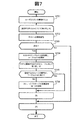
以下、本実施形態で行われる処理を、フローチャートを参照して説明する。 Hereinafter, processing performed in the present embodiment will be described with reference to flowcharts.
図7は、ホスト追加処理のフローチャートである。 FIG. 7 is a flowchart of host addition processing.
ホスト追加処理は、ホストが追加される場合に実行される処理である。 The host addition process is a process executed when a host is added.
S701で、統合レプリケーション管理ソフト211が、ユーザから、追加する全てのホストに関する情報(例えばIPアドレス)の入力を受ける。なお、ユーザからソフト211への情報は、管理サーバ101が備える入力装置を用いて入力されても良いし、遠隔のユーザ端末から入力されても良い。
In step S <b> 701, the integrated
追加するホスト毎に、以下のS702〜S706が行われる。以下、一つのホスト(図7及び図10の説明で「対象ホスト」と言う)を例に採り、S702〜S706を説明する。 The following S702 to S706 are performed for each host to be added. Hereinafter, S702 to S706 will be described by taking one host (referred to as “target host” in the description of FIGS. 7 and 10) as an example.
S702で、ソフト211が、ユーザから入力された情報を用いて対象ホストへの接続確認を行う。
In step S <b> 702, the
S703で、ソフト211が、その接続確認の結果、接続に成功したか否かを判断する。接続に成功した判断されたならば(S703:YES)、S704が行われる。
In step S703, the
S704で、ソフト211が、対象ホストからホストパステーブル210を取得し、そのテーブル210が有する情報を基に、ホストパス管理テーブル214を更新する。例えば、テーブル210が有する情報がテーブル214に追加され、且つ、対象ホストに割り当てられたノードIDもテーブル214に追加される。
In step S <b> 704, the
ホストに直結されている全てのローカルストレージについて、S705及びS706が行われる。 Steps S705 and S706 are performed for all local storages directly connected to the host.
S705で、ソフト211が、対象ホストに直結されているローカルストレージのストレージ番号がストレージテーブル216に登録済みか否かを判断する。この判断の結果が否定的の場合に限り(S705:NO)、S706が行われる。
In step S <b> 705, the
S706で、ソフト211が、図10の処理(ストレージパステーブル収集処理)を実行する。それにより、ストレージテーブル216及びストレージパス管理テーブル215が更新される。
In step S706, the
図8は、構成変更処理のフローチャートである。 FIG. 8 is a flowchart of the configuration change process.
構成変更処理は、構成変更(例えば、パスの追加或いは削除)が行われる場合、或いは、各パスの負荷を取得する場合に行われる処理である。 The configuration change process is a process performed when a configuration change (for example, addition or deletion of a path) is performed or when a load of each path is acquired.
S801で、統合レプリケーション管理ソフト211が、ストレージパス管理テーブル215、ストレージテーブル216及び経路テーブル217を削除する。
In step S801, the integrated
ホストパス管理テーブル214に情報が登録されているホスト毎に、以下のS802〜S807が行われる。以下、一つのホスト(図8及び図10の説明で「対象ホスト」と言う)を例に採り、S802〜S807を説明する。 The following S802 to S807 are performed for each host whose information is registered in the host path management table 214. Hereinafter, taking one host (referred to as “target host” in the description of FIGS. 8 and 10) as an example, S802 to S807 will be described.
S802で、ソフト211が、対象ホストへの接続確認を行う。
In step S802, the
S803で、ソフト211が、その接続確認の結果、接続に成功したか否かを判断する。接続に成功した判断されたならば(S803:YES)、S804が行われ、接続に失敗したと判断されたならば(S803:NO)、S807が行われる。
In step S803, the
S804で、ソフト211が、対象ホストからホストパステーブル210を取得し、そのテーブル210が有する情報を基に、ホストパス管理テーブル214を更新する。
In step S804, the
対象ホストに直結されている全てのローカルストレージについて、S805及びS806が行われる。 S805 and S806 are performed for all local storages directly connected to the target host.
S805で、ソフト211が、対象ホストに直結されているローカルストレージのストレージ番号がストレージテーブル216に登録済みか否かを判断する。この判断の結果が否定的の場合に限り(S805:NO)、S806が行われる。
In step S805, the
S806で、ソフト211が、図10の処理(ストレージパステーブル収集処理)を実行する。それにより、ストレージテーブル216及びストレージパス管理テーブル215が更新される。
In step S806, the
S807で、ソフト211が、ホストパス管理テーブル214における、対象ホストに対応する「状態」の値を、「エラー」に更新する。
In step S <b> 807, the
図9は、ホスト削除処理のフローチャートである。 FIG. 9 is a flowchart of the host deletion process.
S901で、統合レプリケーション管理ソフト211が、ユーザから、削除するホストの指定を受ける(例えば削除対象のホストの名称の入力を受ける)。
In step S901, the integrated
S902で、ソフト211は、ホストパス管理テーブル214及び経路テーブル217から、指定されたホストが関わるレコード(行)を削除する。
In step S902, the
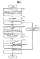
図10は、ストレージパステーブル収集処理のフローチャートを示す。 FIG. 10 shows a flowchart of storage path table collection processing.
この処理では、下記3つの引数:
(1)引数V(要求先のストレージのストレージ番号);
(2)引数R(ルートリスト);
(3)引数H(対象ホストのノードID);
が使用される。
In this process, the following three arguments:
(1) Argument V (storage number of the requested storage);
(2) Argument R (route list);
(3) Argument H (node ID of the target host);
Is used.
S1001で、ソフト211が、引数Hに対応した対象ホストを介して、引数Vと引数Rとを指定したテーブルリクエストを発行する。それにより、ソフト211は、引数Vに対応したストレージから、ストレージパステーブル242を取得する。ソフト211は、そのテーブル242が有する情報を基に、ストレージパス管理テーブル215を更新する。具体的には、テーブル242が有する情報のうち、送信側ストレージ番号、受信側ストレージ番号、回線帯域、データ量及び状態が、ストレージパステーブル242に登録される。なお、このS1001では、引数Vは、対象ホストに直結されているローカルストレージである。故に、引数Rは、このS1001ではnullである(或いは、ローカルストレージのストレージ番号のみを含んでいる)。
In step S <b> 1001, the
S1002で、ソフト211が、引数Vをストレージテーブル216に追加する。
In step S <b> 1002, the
S1003で、ソフト211が、引数Vに対応したノードID(エンドノードID)と、引数Rと、引数H(スタートノードID)を、経路テーブル217に追加する。
In step S <b> 1003, the
S1004で、ソフト211が、引数Vにストレージが訪問済みであることを表す情報をメモリに記録する。
In step S1004, the
取得されたストレージパステーブル242に受信側ストレージ番号が登録されている場合、S1005〜S1008が行われる。 When the receiving storage number is registered in the acquired storage path table 242, S1005 to S1008 are performed.
S1005で、ソフト211が、引数Vを、受信側ストレージ番号に更新する。
In step S1005, the
S1006で、ソフト211が、更新後の引数Vに対応したストレージを訪問したか否かを判断する。その判断の結果が否定的の場合に(S1006:NO)、S1007が行われる。
In step S1006, the
S1007で、ソフト211が、引数Rに更新後の引数Vを追加する。これにより、引数Rに記述されているストレージ番号のリストの末尾に、更新後の引数Vが追加される。
In step S1007, the
S1008で、ソフト211が、S1001と同様に、引数Hが表す対象ホストを介して、更新後の引数Vと更新後の引数Rとを指定したテーブルリクエストを送信する。そのテーブルリクエストは、その引数Rに従う順序でストレージを経由し、引数Vに対応したストレージに届く。そして、そのストレージが有するストレージパステーブル242が、引数Rに従う順序と逆の順序でストレージを経由し、引数Hに対応した対象ホストを介して、管理サーバ101に届く。そのストレージパステーブル242に受信側ストレージ番号が記述されている場合に、S1005〜S1008が行われる。なお、このS1008は、S1001の処理の再帰呼び出しである。
In step S1008, the
このストレージパステーブル収集処理により、対象ホストに直結されているローカルストレージを含んだストレージカスケードにおける全てのストレージから、ローカルストレージに近いストレージから順に、ストレージパステーブル242を取得することができる。この処理は、図7によれば、追加された全てのホストについて行われ、図8によれば、ホストパス管理テーブル214に登録されている全てのホストについて行われる。すなわち、ソフト211は、どのホストからも、そのホストに直結されているローカルストレージを含んだストレージカスケード内の全てのストレージがそれぞれ有するストレージパステーブル242を取得する。
By this storage path table collection processing, the storage path table 242 can be acquired in order from the storage closest to the local storage from all the storage cascades including the local storage directly connected to the target host. This processing is performed for all the added hosts according to FIG. 7, and is performed for all the hosts registered in the host path management table 214 according to FIG. In other words, the
図12及び図13は、スキャン処理のフローチャートである。 12 and 13 are flowcharts of the scanning process.
S1201で、統合レプリケーション管理ソフト211が、ユーザから、下記の3つの情報要素:
(K1)スキャン対象のストレージのストレージ番号;
(K2)スキャン対象のVOLの範囲(例えばVOLの番号の範囲);
(K3)スキャン結果情報の反映先の構成ファイルのファイル名;
の入力を受ける。
In S1201, the integrated
(K1) Storage number of storage to be scanned;
(K2) VOL range to be scanned (for example, VOL number range);
(K3) File name of the configuration file to which the scan result information is reflected;
Receive input.
S1202で、ソフト211は、上記(K2)に属するVOLの情報が他の構成ファイルに格納済みか否かを調べる。S1202の判断の結果が肯定的であれば(S1202:YES)、スキャン処理が終了となる。一方、S1202の判断の結果が否定的であれば(S1202:NO)、S1203が行われる。
In S1202, the
S1203で、ソフト211は、上記(K1)がホストパス管理テーブル214に登録されているか否か、つまり、上記(K1)に対応したストレージがローカルストレージか否かを判断する。
In step S1203, the
S1203の判断の結果が肯定的であれば(S1203:YES)、ローカルスキャンが行われる。すなわち、ソフト211は、上記(K1)のローカルストレージに接続されているホストから、上記(K1)及び(K2)を含んだローカルスキャンのコマンドを送信させる(S1208)。これにより、ソフト211は、ホストを通じて、上記(K1)のローカルストレージから、上記(K2)に属するVOLに関するスキャン結果情報を取得し、その情報を、上記(K3)の構成ファイルに格納する。ソフト211は、経路テーブル217を参照して、上記(K1)のローカルストレージに対応した他のホスト(そのローカルストレージに一又は複数のパスを介して繋がっているホスト)を特定し、特定された他のホストに、上記(K3)の構成ファイルを転送する(S1209)。
If the result of the determination in S1203 is affirmative (S1203: YES), a local scan is performed. That is, the
一方、S1203の判断の結果が否定的であれば(S1203:NO)、リモートスキャンが行われる。具体的には、S1204〜S1207、S1210、S1211〜S1218の処理が行われる。 On the other hand, if the result of the determination in S1203 is negative (S1203: NO), remote scanning is performed. Specifically, the processes of S1204 to S1207, S1210, and S1211 to S1218 are performed.
S1204で、ソフト211は、図11に示す配列作成処理を行うことで、図5Aに示した配列(W1)212と、図5Bに示した配列(W2)213を作成する。
In step S1204, the
S1205で、ソフト211は、図14及び図15に示す距離/重み計算処理を行うことで、経路の距離と重みを算出する。
In step S1205, the
S1206で、ソフト211は、経路テーブル217から、上記(K1)のストレージまでの経路の距離が最も短いホストを選択する。
In step S1206, the
S1207で、ソフト211は、経路テーブル217と、配列(W1)212及び/又は配列(W2)213とを基に、S1206で選択したホストから上記(K1)のストレージまでの経路に∞のパスがあるか否かを判断する。例えば、その経路に含まれるいずれかのパス(ホストパス又はストレージパス)の状態が「エラー」となっていると、そのパスについてのW1[i][j]及びW2[i][j]の値が∞となる。この判断の結果が肯定的の場合(S1207:YES)、ソフト211は、所定のエラー処理を行って(S1210)、このスキャン処理を終了する。一方、この判断の結果が否定的の場合(S1207:NO)、図13のS1211が行われる。
In step S1207, the
S1211で、ソフト211は、最短距離の経路が複数存在するか否か、すなわち、S1206で選択されたホストが複数個存在するか否かを判断する。この判断の結果が否定的の場合(S1211:NO)、S1215が行われる。一方、この判断の結果が肯定的の場合(S1211:YES)、S1212が行われる。
In step S1211, the
S1212で、ソフト211は、S1206で選択された複数のホストのうち、重みが最も小さい経路のスタートノードのホストを選択する。
In step S1212, the
S1213で、ソフト211は、最短距離且つ重みが最も小さい経路が複数存在するか否か、すなわち、S1212で選択されたホストが複数個存在するか否かを判断する。この判断の結果が否定的の場合(S1213:NO)、S1215が行われる。一方、この判断の結果が肯定的の場合(S1213:YES)、S1214が行われる。
In step S1213, the
S1214で、ソフト211は、ホストパス管理テーブル214を参照し、S1212で選択された複数のホストのち、CPUサイクル時間が最も短いホストを選択する。
In step S1214, the
S1215で、ソフト211は、S1206、S1212又はS1214で選択された一つのホストに関する情報を、引数Aとして設定する。以下、引数Aに対応したホストを「ホストA」と言う。
In step S1215, the
S1216で、ソフト211は、ホストAに、リモートスキャンを実行させる。具体的には、例えば、ソフト211は、ホストAから上記(K1)のストレージまでの経路に対応したルートリストと、上記(K1)及び(K2)とを含んだリモートスキャンのコマンドを、ホストAから送信させる。これにより、ソフト211は、ホストAを通じて、上記(K1)のローカルストレージから、上記(K2)に属するVOLに関するスキャン結果情報を取得する。ソフト211は、その情報を、上記(K3)の構成ファイルに格納し、その構成ファイルをホストAに格納する(S1217)。ソフト211は、経路テーブル217を参照して、上記(K1)のローカルストレージに対応した他のホスト(そのローカルストレージに一又は複数のパスを介して繋がっているホスト)を特定し、特定された他のホストに、上記(K3)の構成ファイルを転送する(S1218)。
In step S1216, the
図11は、配列作成処理のフローチャートである。この処理は、図12のS1205の処理である。 FIG. 11 is a flowchart of the array creation process. This process is the process of S1205 in FIG.
S1101で、ソフト211は、引数nとして、ディスカバリしているホストの数(ホストパス管理テーブル214に登録されているホストの数)を設定する。
In step S1101, the
S1102で、ソフト211は、引数mとして、ストレージテーブル216に登録されているストレージの数を設定する。
In step S1102, the
S1103で、ソフト211は、長さn+mの配列(W1)及び(W2)を作成する。この段階では、配列(W1)及び(W2)も、縦軸[i](iは、1から(n+m)までの整数)と、横軸[j](jは、1から(n+m)までの整数)とを有するが、iとjが交差する各セルはブランクである。
In step S1103, the
S1104〜S1108が、iとjの全ての組合せ(パターン)について行われる。 S1104 to S1108 are performed for all combinations (patterns) of i and j.
S1104で、ソフト211は、任意に選択したiの値が、ホストパス管理テーブル214に登録されているいずれかのノードID(ホストのノードID)と一致するか否かを判断する。この判断の結果が肯定的の場合、S1107が行われる(この場合、ホスト[i]と言う)。一方、この判断の結果が否定的の場合、S1105が行われる(この場合、ストレージ[i]と言う。
In step S <b> 1104, the
S1105で、ソフト211は、ストレージパス管理テーブル215を参照し、送信側ストレージ[i]に対応した受信側ストレージ[j]があり、且つ、送信側ストレージ[i]から受信側ストレージ[j]へのストレージパスの状態が正常か否かを判断する。この判断の結果が肯定的の場合、S1106が行われ、この判断の結果が否定的の場合、S1108が行われる。
In step S1105, the
S1106で、ソフト211は、W1[i][j]=1を設定する。すなわち、ソフト211は、配列(W1)212の、[i]と[j]が交差するセルに、「1」を設定する。また、ソフト211は、W2[i][j]=(データ量÷回線帯域)を設定する。すなわち、ソフト211は、配列(W2)213の、[i]と[j]が交差するセルに、(データ量÷回線帯域)を設定する。それらのデータ量及び回線帯域は、それぞれ、ノード[i]からノード[j]へのパスに対応した値である。
In step S1106, the
S1107で、ソフト211は、ホストパス管理テーブル214を参照し、ホスト[i]に直結したローカルストレージ[j]があり、且つ、ホスト[i]からローカルストレージ[j]へのホストパスの状態が正常か否かを判断する。この判断の結果が肯定的の場合、S1106が行われ、この判断の結果が否定的の場合、S1108が行われる。
In S1107, the
S1108で、ソフト211は、W1[i][j]=∞、及び、W2[i][j]=∞を設定する。
In step S1108, the
S1104〜S1108が、iとjの全ての組合せについて行われることで、図5Aに示した配列(W1)212、及び、図5Bに示した配列(W2)213が完成する。 By performing S1104 to S1108 for all combinations of i and j, the array (W1) 212 shown in FIG. 5A and the array (W2) 213 shown in FIG. 5B are completed.
図14及び図15は、距離/重み計算処理のフローチャートである。この処理は、図12のS1205の処理である。 14 and 15 are flowcharts of the distance / weight calculation process. This process is the process of S1205 in FIG.
フローチャートを用いて距離/重み計算処理を説明する前に、本実施形態に係る距離/重み計算処理の概要を説明する。 Before describing the distance / weight calculation process using the flowchart, an outline of the distance / weight calculation process according to the present embodiment will be described.
本実施形態に係るシステム構成(ホストとストレージを含んだシステムの構成)は、ノード(ストレージ、ホスト)を頂点と考えると、非連結の有効グラフと考えることができる。 The system configuration according to the present embodiment (system configuration including a host and a storage) can be considered as an unconnected effective graph when a node (storage, host) is considered as a vertex.
各頂点(vertex)は、フィールド「distance」、「load」及び「status」を持つ。distanceは、引数で指定した頂点とこの頂点との距離を表す。loadは、引数で指定した頂点とこの頂点の間の経路の重みを表す。statusは、この頂点を訪問したかどうかを表す。 Each vertex has fields “distance”, “load” and “status”. distance represents the distance between the vertex specified by the argument and this vertex. load represents the weight of the path between the vertex specified by the argument and this vertex. status indicates whether or not this vertex has been visited.
全ての頂点について、distance及びloadのそれぞれの初期値は、「∞」とされ、statusの初期値は、unvisited(未訪問)とされる。ただし、引数で指定された頂点のdistanceとloadは、自分自身であるため0(ゼロ)に初期化される。 For all vertices, the initial values of distance and load are “∞”, and the initial value of status is unvisited (unvisited). However, the distance and load at the vertex specified by the argument are themselves and are initialized to 0 (zero).
この処理では、unvisitedかつ最少のdistanceを持つ頂点pが選択され、その頂点から接続関係にある全ての頂点のdistanceとloadが計算される。図14及び図15に示す(B)のループで各頂点が頂点pとなるようにすることで、全ての頂点のdistance及びloadが計算される。 In this process, a vertex p having an unvisited minimum distance is selected, and the distances and loads of all the vertices connected to the vertex are calculated. The distances and loads of all the vertices are calculated by causing each vertex to become the vertex p in the loop of (B) shown in FIGS. 14 and 15.
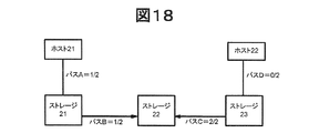
図18に示すシステム構成の例において、例えば、ホスト21からスキャン対象ストレージ2までの経路の距離は、2つのパスA及びBを有するため、「2」となる(以下、その経路を「経路AB」と表現する)。一方、ホスト22からスキャン対象ストレージ2までの経路の距離も、2つのパスD及びCを有するため、「2」となる(以下、その経路を「経路DC」と表現する)。
In the example of the system configuration shown in FIG. 18, for example, the distance of the route from the
経路の重みの定義の仕方としては、複数の方法、例えば次の2種類がある。図14及び図15のフローチャートは、下記<方法1>を表現している。
There are a plurality of methods for defining route weights, for example, the following two types. The flowcharts of FIGS. 14 and 15 express the following <
<方法1>
経路上の各パスの重み(データ量÷回線)の最大値が採用される。この方法によれば、経路ABの重みは、パスAの重み「1/2」とパスBの重み「1/2」のうちの最大値(max(1/2,1/2))=1/2となる。一方、経路DCの重みは、パスDの重み「0/2」とパスCの重み「2/2」のうちの最大値(max(0/2,2/2))=2/2となる。
<
The maximum value of the weight (data amount / line) of each path on the route is adopted. According to this method, the weight of the route AB is the maximum value (max (1/2, 1/2)) = 1 of the weight “1/2” of the path A and the weight “1/2” of the path B = 1. / 2. On the other hand, the weight of the route DC is the maximum value (max (0/2, 2/2)) = 2/2 of the weight “0/2” of the path D and the weight “2/2” of the path C. .
<方法2>
経路上の各パスの重み(データ量÷回線)の平均が採用される。この方法によれば、経路ABの重みは、パスAの重み「1/2」とパスBの重み「1/2」の平均((1/2+1/2)÷2)=1/2となる。一方、経路DCの重みは、パスDの重み「0/2」とパスCの重み「2/2」の平均((0/2+2/2)÷2)=1/2となる。
<
The average of the weight (data amount / line) of each path on the route is adopted. According to this method, the weight of the route AB is the average of the weight “1/2” of the path A and the weight “1/2” of the path B ((1/2 + 1/2) / 2) = 1/2. . On the other hand, the weight of the route DC is the average of the weight “0/2” of the path D and the weight “2/2” of the path C ((0/2 + 2/2) / 2) = ½.
以下、図14及び図15を参照して、距離/重み計算処理を詳細に説明する。 Hereinafter, the distance / weight calculation process will be described in detail with reference to FIGS. 14 and 15.
S1401で、ソフト211が、下記の設定:
(1)引数n=ディスカバリしているホストの数(ホストパス管理テーブル214に登録されているホストの数);
(2)引数m=ストレージテーブル216に登録されているストレージの数;
(3)(n+m)×(n+m)の配列(vertex);
を行う。ここでの(n+m)は、フィールド「distance」、「load」及び「status」を持つオブジェクトの長さ(数)である。
In step S1401, the
(1) Argument n = Number of discovered hosts (number of hosts registered in the host path management table 214);
(2) Argument m = number of storages registered in the storage table 216;
(3) (n + m) × (n + m) sequence (vertex);
I do. Here, (n + m) is the length (number) of objects having fields “distance”, “load”, and “status”.
S1402が、x=1から(n+m)までの整数のそれぞれについて行われる。すなわち、ソフト211は、下記の設定:
(1)vertex(x).distance=∞;
(2)vertex(x).load=∞;
(3)vertex(x).state=unvisited;
を行う。
S1402 is performed for each of the integers from x = 1 to (n + m). That is, the
(1) vertex (x) .distance = ∞;
(2) vertex (x) .load = ∞;
(3) vertex (x) .state = unvisited;
I do.
S1403で、ソフト211は、vertex(x).distanceを0(ゼロ)に更新し、同様に、vertex(x).loadを0(ゼロ)に更新する。
In S1403, the
配列(W1)212及び配列(W2)213の値[i]として、1から(n+m)までの整数があるが、各整数について、S1404〜S1409が行われる。 There are integers from 1 to (n + m) as the values [i] of the array (W1) 212 and the array (W2) 213, and S1404 to S1409 are performed for each integer.
S1404で、ソフト211は、「min=∞」を設定する。そして、ソフト211は、x=1から(n+m)までの整数のそれぞれについて、S1405及びS1406を行う。すなわち、S1405で、ソフト211は、「vertex(x).state=unvisited」且つ「vertex(x).distance<min」か否かを判断する。この判断の結果が肯定的であれば(S1405:YES)、ソフト211は、S1406で、「p=x」且つ「min=distance」を設定する。つまり、変数pの値として、現在のxの値が設定され、変数minとして、現在のdistanceの値が設定される。
In S1404, the
S1407で、ソフト211は、「min=∞」か否かを判断する。この判断の結果が肯定的であれば(S1407:YES)、S1410が行われ、この判断の結果が否定的であれば(S1407:NO)、S1408が行われる。
In step S1407, the
S1408で、ソフト211は、vertex(x).stateの値を「visited」に更新する。
In step S1408, the
ソフト211は、x=1から(n+m)までの整数のそれぞれについて、S1409を行う。すなわち、S1409で、ソフト211は、下記の設定:
(1)vertex(x).distance=min
(vertex(x).distance, vertex(p).distance+W1[x][p]);
(2)vertex(x).load=max
(vertex(p).load, W2[x][p]);
を行う。なお、これは、上記<方法1>及び<方法2>のうちの<方法1>についての説明であるが、<方法2>が採用された場合、vertex(x).loadは、「vertex(x).load=min (vertex(x).load, vertex(p).load+W2[x][p])」である。
The
(1) vertex (x) .distance = min
(vertex (x) .distance, vertex (p) .distance + W1 [x] [p]);
(2) vertex (x) .load = max
(vertex (p) .load, W2 [x] [p]);
I do. Note that this is an explanation of <
以上のS1404〜S1409の処理が、i=1から(n+m)までのそれぞれの整数について行われる。 The above processes of S1404 to S1409 are performed for each integer from i = 1 to (n + m).
その後、ソフト211は、x=1から(n+m)までの整数のそれぞれについて、S1410及びS1411を行う。すなわち、S1410で、ソフト211は、vertex(x)の値がホストのノードIDと一致するか否かを判断する。この判断の結果が否定的であれば(S1410:NO)、ソフト211は、S1411で、x、start、vertex(x).distance、及びvertex(x).loadを、経路テーブル217に登録する。
Thereafter, the
以上、上述した実施形態によれば、スキャン処理の前に、管理サーバ101が、ホスト1及び2とストレージカスケード(ストレージ1〜4)とを含んだ計算機システムに存在する全ての経路の構成を把握する(具体的には、経路テーブル217が構築される)。そして、スキャン処理では、経路テーブル217を参照して、管理サーバ101が、スキャン対象のリモートストレージをエンドノードとする複数の経路のうちの最適な経路のスタートノードのホストを選択する。最適な経路とは、前述したように、例えば、最短経路及び負荷最小経路である。これにより、リモートスキャンのコマンドを発行するのに最適なホスト計算機を選択できる確率が高まる。
As described above, according to the above-described embodiment, before the scan process, the
以上、本発明の一つの実施形態を説明したが、本発明は、この実施形態に限定されるものでなく、その要旨を逸脱しない範囲で種々変更可能であることはいうまでもない。例えば、ホスト、ストレージ及びストレージカスケードの数は、上記例に限られない。また、「直列に接続された複数のストレージシステム」とは、必ずしも一列のストレージカスケードである必要は無く、例えば図19に示すように、途中で枝分かれすることで、複数のストレージカスケード(例えば、ストレージ11、12及び15のカスケードと、ストレージ11、12、13及び14のカスケードと、ストレージ15、12、13及び14のカスケード)が含まれても良い。
Although one embodiment of the present invention has been described above, the present invention is not limited to this embodiment, and it goes without saying that various modifications can be made without departing from the scope of the present invention. For example, the number of hosts, storages, and storage cascades is not limited to the above example. In addition, “a plurality of storage systems connected in series” does not necessarily need to be a single row of storage cascades. For example, as shown in FIG. 11, 12 and 15, a
101…管理サーバ 101 ... Management server
Claims (13)
記憶資源と、
前記ネットワークインターフェイス及び前記記憶資源に接続されたプロセッサと
を備え、
前記通信ネットワークに複数のホスト計算機が接続されており、
1以上のストレージカスケードを構成する複数のストレージシステムがあり、
1つのストレージカスケードは、直列に接続された二以上のストレージシステムで構成されており、
前記複数のストレージシステムには、二以上のローカルストレージと一以上のリモートストレージが含まれており、
前記ローカルストレージは、少なくとも一つのホスト計算機に接続されているストレージシステムであり、
前記リモートストレージは、いずれのホスト計算機にも接続されていないストレージシステムであり、
前記プロセッサが、経路調査処理と、スキャン支援処理とを実行し、
(A)前記経路調査処理は、
(a1)ホスト計算機とローカルストレージとを接続するパスであるホストパスに関するホスト/ストレージ接続情報を前記ネットワークインターフェイスを通じて取得する処理と、
(a2)ストレージシステムとストレージシステムとを接続するパスであるストレージパスに関するストレージ/ストレージ接続情報を各ホスト計算機及び前記ネットワークインターフェイスを通じて取得する処理と、
(a3)前記(a1)で取得されたホスト/ストレージ接続情報と前記(a2)で取得されたストレージ/ストレージ接続情報とを基に経路管理情報を生成し、生成した経路管理情報を前記記憶資源に格納する処理と
を含み、
前記経路管理情報は、複数の経路に関する情報であり、
一つの経路は、直列に接続された二以上のノードとノード間のパスとで構成されており、その二以上のノードのうちのスタートノードが、いずれかのホスト計算機であり、その二以上のノードうちの他のノードが、いずれかのストレージシステムであり、
(B)前記スキャン処理は、
(b1)前記複数のストレージシステムのうちのスキャン対象のストレージシステムをエンドノードとする複数の経路を前記経路管理情報から特定する処理と、
(b2)前記スキャン対象のストレージシステムがいずれかのリモートストレージであることが前記(b1)の処理においてわかった場合に、前記経路管理情報を基に、前記スキャン対象のリモートストレージからスキャン対象の論理ボリュームに関する情報を取得することであるリモートスキャンを実行するホスト計算機として、前記複数の経路のうちの最適な経路のスタートノードであるホスト計算機を選択する処理と
を含む、
計算機。 A network interface for communicating via a communication network;
Storage resources,
A processor connected to the network interface and the storage resource;
A plurality of host computers are connected to the communication network,
There are multiple storage systems that make up one or more storage cascades,
One storage cascade consists of two or more storage systems connected in series.
The plurality of storage systems include two or more local storages and one or more remote storages,
The local storage is a storage system connected to at least one host computer,
The remote storage is a storage system that is not connected to any host computer,
The processor executes a route investigation process and a scan support process,
(A) The route investigation process
(A1) processing for acquiring host / storage connection information regarding a host path, which is a path connecting the host computer and the local storage, through the network interface;
(A2) processing for acquiring storage / storage connection information regarding a storage path, which is a path connecting the storage system and the storage system, through each host computer and the network interface;
(A3) Route management information is generated based on the host / storage connection information acquired in (a1) and the storage / storage connection information acquired in (a2), and the generated path management information is stored in the storage resource. Processing to store in,
The route management information is information regarding a plurality of routes,
One path is composed of two or more nodes connected in series and a path between the nodes, and the start node of the two or more nodes is any host computer, and the two or more nodes. The other node is one of the storage systems,
(B) The scan process includes
(B1) processing for specifying a plurality of paths from the path management information with the storage system to be scanned among the plurality of storage systems as an end node;
(B2) When it is found in the process of (b1) that the storage system to be scanned is one of the remote storages, the logical system to be scanned from the remote storage to be scanned is based on the path management information. Including a process of selecting a host computer that is a start node of an optimum path among the plurality of paths as a host computer that executes a remote scan that is to acquire information about a volume,
calculator.
経路の距離は、スタートノードとエンドノードとの間に存在するストレージシステムの数であり、
経路の負荷は、その経路が有する各パスの負荷を基に定まる負荷である、
請求項1記載の計算機。 The optimum route is a route selected based on at least one of a distance of each route, a route load, and a node load;
The path distance is the number of storage systems that exist between the start node and end node,
The route load is a load determined based on the load of each path of the route.
The computer according to claim 1.
前記最短経路は、前記スキャン対象のリモートストレージとスタートノードのホスト計算機との間に存在するストレージシステムの数が最も少ない経路である、
請求項2記載の計算機。 The optimal route is the shortest route,
The shortest path is a path with the smallest number of storage systems existing between the remote storage to be scanned and the host computer of the start node.
The computer according to claim 2.
前記ストレージ/ストレージ接続情報は、前記ストレージパスについての負荷を表す情報を含み、
前記プロセッサは、前記ホスト/ストレージ接続情報及び前記ストレージ/ストレージ接続情報が表すノード間のパス毎の負荷を基に、経路毎の負荷を算出し、
二以上の最短経路がある場合、前記最適な経路は、前記二以上の最短経路のうちの、負荷が最小の経路である負荷最小経路である、
請求項3記載の計算機。 The host / storage connection information includes information indicating a load on the host path,
The storage / storage connection information includes information indicating a load on the storage path,
The processor calculates a load for each path based on the load for each path between the nodes represented by the host / storage connection information and the storage / storage connection information,
When there are two or more shortest paths, the optimal path is a minimum load path that is a path with the minimum load among the two or more shortest paths.
The computer according to claim 3.
請求項4記載の計算機。 When there are two or more load minimum paths, the optimum path is a path with the minimum load on the node among the two or more load minimum paths.
The computer according to claim 4.
請求項5記載の計算機。 Of the two or more host computers belonging to the two or more load minimum paths, the host computer having the smallest load is selected.
The computer according to claim 5.
前記ストレージ/ストレージ接続情報は、前記ストレージパスについての負荷を表す情報を含み、
前記プロセッサは、前記ホスト/ストレージ接続情報及び前記ストレージ/ストレージ接続情報が表すノード間のパス毎の負荷を基に、経路毎の負荷を算出し、
前記最適な経路は、負荷が最小の経路である負荷最小経路である、
請求項6記載の計算機。 The host / storage connection information includes information indicating a load on the host path,
The storage / storage connection information includes information indicating a load on the storage path,
The processor calculates a load for each path based on the load for each path between the nodes represented by the host / storage connection information and the storage / storage connection information,
The optimal path is a minimum load path that is a path with a minimum load.
The computer according to claim 6.
請求項7記載の計算機。 The selected host computer is a start node of a path with a minimum load on the node.
The computer according to claim 7.
前記スキャン対象のリモートストレージから、そのスキャンコマンドに応答して、そのスキャンコマンドで指定されている前記スキャン対象の論理ボリュームに関するスキャン結果情報が送信され、そのスキャン結果情報が、前記転送順序と逆の順序で転送されて、前記スキャンコマンドを発行したホスト計算機に受信され、
前記プロセッサが、前記スキャン対象のリモートストレージをエンドノードとする前記複数の経路のうちの前記最適な経路以外の経路のスタートノードのホスト計算機に、前記スキャン結果情報を送信する、
請求項8記載の計算機。 A scan command in which the transfer order according to the optimum path and the logical volume to be scanned are specified is issued from the host computer that has received an instruction to execute the remote scan via the optimum path, and the scan The command is received by the local storage connected to the host computer, transferred according to the transfer order specified by the scan command, and received by the remote storage to be scanned,
In response to the scan command, scan result information related to the scan target logical volume specified by the scan command is transmitted from the scan target remote storage, and the scan result information is reverse to the transfer order. Transferred in order, received by the host computer that issued the scan command,
The processor transmits the scan result information to a host computer of a start node of a path other than the optimal path among the plurality of paths having the remote storage to be scanned as an end node;
The computer according to claim 8.
請求項9記載の計算機。 The optimal path is a path selected based on at least two of a path distance difference, a path load difference, and a node load difference;
The computer according to claim 9.
前記プロセッサは、前記(b2)の処理において、更に、以下の処理:
二以上の負荷最小経路がある場合、前記二以上の負荷最小経路に属する二以上のホスト計算機のうち、CPU性能が最も高いホスト計算機を選択する、
を行う、
請求項10記載の計算機。 The host / storage connection information includes information representing the CPU performance of the host computer,
In the processing (b2), the processor further performs the following processing:
When there are two or more load minimum paths, a host computer having the highest CPU performance is selected from two or more host computers belonging to the two or more load minimum paths.
I do,
The computer according to claim 10.
1つのストレージカスケードは、直列に接続された二以上のストレージシステムで構成されており、
前記複数のストレージシステムには、二以上のローカルストレージと一以上のリモートストレージが含まれており、
前記ローカルストレージは、少なくとも一つのホスト計算機に接続されているストレージシステムであり、
前記リモートストレージは、いずれのホスト計算機にも接続されていないストレージシステムであり、
前記スキャン方法は、経路調査処理とスキャン処理とを実行し、
(A)前記経路調査処理は、
(a1)ホスト計算機とローカルストレージとを接続するパスであるホストパスに関するホスト/ストレージ接続情報を前記ネットワークインターフェイスを通じて取得する処理と、
(a2)ストレージシステムとストレージシステムとを接続するパスであるストレージパスに関するストレージ/ストレージ接続情報を各ホスト計算機及び前記ネットワークインターフェイスを通じて取得する処理と、
(a3)前記(a1)で取得されたホスト/ストレージ接続情報と前記(a2)で取得されたストレージ/ストレージ接続情報とを基に経路管理情報を生成し、生成した経路管理情報を前記記憶資源に格納する処理と
を含み、
前記経路管理情報は、複数の経路に関する情報であり、
一つの経路は、直列に接続された二以上のノードとノード間のパスとで構成されており、その二以上のノードのうちのスタートノードが、いずれかのホスト計算機であり、その二以上のノードうちの他のノードが、いずれかのストレージシステムであり、
(B)前記スキャン処理は、
(b1)前記複数のストレージシステムのうちのスキャン対象のストレージシステムをエンドノードとする複数の経路を前記経路管理情報から特定する処理と、
(b2)前記スキャン対象のストレージシステムがいずれかのリモートストレージであることが前記(b1)の処理においてわかった場合に、前記経路管理情報を基に、前記スキャン対象のリモートストレージからスキャン対象の論理ボリュームに関する情報を取得することであるリモートスキャンを実行するホスト計算機として、前記複数の経路のうちの最適な経路のスタートノードであるホスト計算機を選択する処理と
を含む、
スキャン方法。 A scanning method for causing a host computer to acquire information about a logical volume to be scanned from any of a plurality of storage systems that constitute one or more storage cascades,
One storage cascade consists of two or more storage systems connected in series.
The plurality of storage systems include two or more local storages and one or more remote storages,
The local storage is a storage system connected to at least one host computer,
The remote storage is a storage system that is not connected to any host computer,
The scan method performs a route investigation process and a scan process,
(A) The route investigation process
(A1) processing for acquiring host / storage connection information regarding a host path, which is a path connecting the host computer and the local storage, through the network interface;
(A2) processing for acquiring storage / storage connection information regarding a storage path, which is a path connecting the storage system and the storage system, through each host computer and the network interface;
(A3) Route management information is generated based on the host / storage connection information acquired in (a1) and the storage / storage connection information acquired in (a2), and the generated path management information is stored in the storage resource. Processing to store in,
The route management information is information regarding a plurality of routes,
One path is composed of two or more nodes connected in series and a path between the nodes, and the start node of the two or more nodes is any host computer, and the two or more nodes. The other node is one of the storage systems,
(B) The scan process includes
(B1) processing for specifying a plurality of paths from the path management information with the storage system to be scanned among the plurality of storage systems as an end node;
(B2) When it is found in the process of (b1) that the storage system to be scanned is one of the remote storages, the logical system to be scanned from the remote storage to be scanned is based on the path management information. Including a process of selecting a host computer that is a start node of an optimum path among the plurality of paths as a host computer that executes a remote scan that is to acquire information about a volume,
Scan method.
1つのストレージカスケードは、直列に接続された二以上のストレージシステムで構成されており、
前記複数のストレージシステムには、二以上のローカルストレージと一以上のリモートストレージが含まれており、
前記ローカルストレージは、少なくとも一つのホスト計算機に接続されているストレージシステムであり、
前記リモートストレージは、いずれのホスト計算機にも接続されていないストレージシステムであり、
前記コンピュータプログラムは、経路調査処理とスキャン処理とをコンピュータに実行させ、
(A)前記経路調査処理は、
(a1)ホスト計算機とローカルストレージとを接続するパスであるホストパスに関するホスト/ストレージ接続情報を前記ネットワークインターフェイスを通じて取得する処理と、
(a2)ストレージシステムとストレージシステムとを接続するストレージパスに関するストレージ/ストレージ接続情報を各ホスト計算機及び前記ネットワークインターフェイスを通じて取得する処理と、
(a3)前記(a1)で取得されたホスト/ストレージ接続情報と前記(a2)で取得されたストレージ/ストレージ接続情報とを基に経路管理情報を生成し、生成した経路管理情報を前記記憶資源に格納する処理と
を含み、
前記経路管理情報は、複数の経路に関する情報であり、
一つの経路は、直列に接続された二以上のノードとノード間のパスとで構成されており、その二以上のノードのうちのスタートノードが、いずれかのホスト計算機であり、その二以上のノードうちの他のノードが、いずれかのストレージシステムであり、
(B)前記スキャン処理は、
(b1)前記複数のストレージシステムのうちのスキャン対象のストレージシステムをエンドノードとする複数の経路を前記経路管理情報から特定する処理と、
(b2)前記スキャン対象のストレージシステムがいずれかのリモートストレージであることが前記(b1)の処理においてわかった場合に、前記経路管理情報を基に、前記スキャン対象のリモートストレージからスキャン対象の論理ボリュームに関する情報を取得することであるリモートスキャンを実行するホスト計算機として、前記複数の経路のうちの最適な経路のスタートノードであるホスト計算機を選択する処理と
を含む、
コンピュータプログラム。 A computer program that causes a host computer to acquire information about a logical volume to be scanned from any of a plurality of storage systems that constitute one or more storage cascades,
One storage cascade consists of two or more storage systems connected in series.
The plurality of storage systems include two or more local storages and one or more remote storages,
The local storage is a storage system connected to at least one host computer,
The remote storage is a storage system that is not connected to any host computer,
The computer program causes a computer to execute a route investigation process and a scan process,
(A) The route investigation process
(A1) processing for acquiring host / storage connection information regarding a host path, which is a path connecting the host computer and the local storage, through the network interface;
(A2) processing for acquiring storage / storage connection information related to a storage path connecting the storage system and the storage system through each host computer and the network interface;
(A3) Route management information is generated based on the host / storage connection information acquired in (a1) and the storage / storage connection information acquired in (a2), and the generated path management information is stored in the storage resource. Processing to store in,
The route management information is information regarding a plurality of routes,
One path is composed of two or more nodes connected in series and a path between the nodes, and the start node of the two or more nodes is any host computer, and the two or more nodes. The other node is one of the storage systems,
(B) The scan process includes
(B1) processing for specifying a plurality of paths from the path management information with the storage system to be scanned among the plurality of storage systems as an end node;
(B2) When it is found in the process of (b1) that the storage system to be scanned is one of the remote storages, the logical system to be scanned from the remote storage to be scanned is based on the path management information. Including a process of selecting a host computer that is a start node of an optimum path among the plurality of paths as a host computer that executes a remote scan that is to acquire information about a volume,
Computer program.
Priority Applications (2)
| Application Number | Priority Date | Filing Date | Title |
|---|---|---|---|
| JP2009114130A JP4810585B2 (en) | 2009-05-11 | 2009-05-11 | Calculator that supports remote scan |
| US12/503,529 US8166202B2 (en) | 2009-05-11 | 2009-07-15 | Computer supporting remote scan |
Applications Claiming Priority (1)
| Application Number | Priority Date | Filing Date | Title |
|---|---|---|---|
| JP2009114130A JP4810585B2 (en) | 2009-05-11 | 2009-05-11 | Calculator that supports remote scan |
Publications (3)
| Publication Number | Publication Date |
|---|---|
| JP2010262551A JP2010262551A (en) | 2010-11-18 |
| JP2010262551A5 JP2010262551A5 (en) | 2011-04-14 |
| JP4810585B2 true JP4810585B2 (en) | 2011-11-09 |
Family
ID=43063024
Family Applications (1)
| Application Number | Title | Priority Date | Filing Date |
|---|---|---|---|
| JP2009114130A Expired - Fee Related JP4810585B2 (en) | 2009-05-11 | 2009-05-11 | Calculator that supports remote scan |
Country Status (2)
| Country | Link |
|---|---|
| US (1) | US8166202B2 (en) |
| JP (1) | JP4810585B2 (en) |
Families Citing this family (15)
| Publication number | Priority date | Publication date | Assignee | Title |
|---|---|---|---|---|
| US8521954B2 (en) | 2010-12-03 | 2013-08-27 | Hitachi, Ltd. | Management computer and volume configuration management method |
| US9158714B2 (en) * | 2012-01-31 | 2015-10-13 | Symantec Corporation | Method and system for multi-layer differential load balancing in tightly coupled clusters |
| WO2016121004A1 (en) * | 2015-01-27 | 2016-08-04 | 株式会社日立製作所 | Storage apparatus |
| US11163462B1 (en) * | 2020-04-29 | 2021-11-02 | EMC IP Holding Company LLC | Automated resource selection for software-defined storage deployment |
| US11962518B2 (en) | 2020-06-02 | 2024-04-16 | VMware LLC | Hardware acceleration techniques using flow selection |
| US12021759B2 (en) | 2020-09-28 | 2024-06-25 | VMware LLC | Packet processing with hardware offload units |
| US11606310B2 (en) | 2020-09-28 | 2023-03-14 | Vmware, Inc. | Flow processing offload using virtual port identifiers |
| US11636053B2 (en) | 2020-09-28 | 2023-04-25 | Vmware, Inc. | Emulating a local storage by accessing an external storage through a shared port of a NIC |
| US11829793B2 (en) | 2020-09-28 | 2023-11-28 | Vmware, Inc. | Unified management of virtual machines and bare metal computers |
| US11736566B2 (en) | 2020-09-28 | 2023-08-22 | Vmware, Inc. | Using a NIC as a network accelerator to allow VM access to an external storage via a PF module, bus, and VF module |
| US11863376B2 (en) | 2021-12-22 | 2024-01-02 | Vmware, Inc. | Smart NIC leader election |
| US11995024B2 (en) | 2021-12-22 | 2024-05-28 | VMware LLC | State sharing between smart NICs |
| US11928367B2 (en) | 2022-06-21 | 2024-03-12 | VMware LLC | Logical memory addressing for network devices |
| US11899594B2 (en) | 2022-06-21 | 2024-02-13 | VMware LLC | Maintenance of data message classification cache on smart NIC |
| US11928062B2 (en) | 2022-06-21 | 2024-03-12 | VMware LLC | Accelerating data message classification with smart NICs |
Family Cites Families (9)
| Publication number | Priority date | Publication date | Assignee | Title |
|---|---|---|---|---|
| US5544347A (en) * | 1990-09-24 | 1996-08-06 | Emc Corporation | Data storage system controlled remote data mirroring with respectively maintained data indices |
| JP2004126716A (en) * | 2002-09-30 | 2004-04-22 | Fujitsu Ltd | Data storing method using wide area distributed storage system, program for making computer realize the method, recording medium, and controller in the system |
| JP4401895B2 (en) * | 2004-08-09 | 2010-01-20 | 株式会社日立製作所 | Computer system, computer and its program. |
| JP4476108B2 (en) * | 2004-11-24 | 2010-06-09 | 株式会社日立製作所 | Storage system, computer system, and storage information acquisition method |
| US7647636B2 (en) * | 2005-08-24 | 2010-01-12 | Microsoft Corporation | Generic RootKit detector |
| JP4686305B2 (en) * | 2005-08-26 | 2011-05-25 | 株式会社日立製作所 | Storage management system and method |
| JP5121161B2 (en) * | 2006-04-20 | 2013-01-16 | 株式会社日立製作所 | Storage system, path management method, and path management apparatus |
| US8060297B2 (en) * | 2007-12-14 | 2011-11-15 | Microsoft Corporation | Route transfer between devices |
| JP4977595B2 (en) * | 2007-12-21 | 2012-07-18 | 株式会社日立製作所 | Remote copy system, remote copy environment setting method, data restoration method |
-
2009
- 2009-05-11 JP JP2009114130A patent/JP4810585B2/en not_active Expired - Fee Related
- 2009-07-15 US US12/503,529 patent/US8166202B2/en not_active Expired - Fee Related
Also Published As
| Publication number | Publication date |
|---|---|
| US20100287306A1 (en) | 2010-11-11 |
| US8166202B2 (en) | 2012-04-24 |
| JP2010262551A (en) | 2010-11-18 |
Similar Documents
| Publication | Publication Date | Title |
|---|---|---|
| JP4810585B2 (en) | Calculator that supports remote scan | |
| US7805566B2 (en) | Replication in storage systems using a target port mimicking a host initiator port | |
| US7313636B2 (en) | Methods and structure for supporting persistent reservations in a multiple-path storage environment | |
| US8392931B2 (en) | Data transfer protocol for data replication between multiple pairs of storage controllers on a SAN fabric | |
| JP4963808B2 (en) | Storage control system | |
| KR100995466B1 (en) | Methods and apparatus for implementing virtualization of storage within a storage area network | |
| US7088703B2 (en) | Multipath multihop remote data facility | |
| JP4713902B2 (en) | Storage system | |
| JP4291664B2 (en) | Storage apparatus and system having communication buffer reservation function | |
| KR101196547B1 (en) | A method for deterministic sas discovery and configuration | |
| JP4310070B2 (en) | Storage system operation management method | |
| US20090198956A1 (en) | System and Method for Data Processing Using a Low-Cost Two-Tier Full-Graph Interconnect Architecture | |
| US7839788B2 (en) | Systems and methods for load balancing storage system requests in a multi-path environment based on transfer speed of the multiple paths | |
| JP2005217815A (en) | Path control method | |
| JP2004192105A (en) | Connection device of storage device and computer system including it | |
| CN113485636B (en) | Data access method, device and system | |
| JP2010218364A (en) | Information processing system, and communication control apparatus and method | |
| JP2008228150A (en) | Switch device, and frame switching method and program thereof | |
| JP6025973B2 (en) | Computer system and volume management method for computer system | |
| JP5272185B2 (en) | Computer system and storage system | |
| US20040024887A1 (en) | Method, system, and program for generating information on components within a network | |
| JPWO2009084314A1 (en) | Data distributed storage method and data distributed storage system | |
| US9436653B2 (en) | Shared-bandwidth multiple target remote copy | |
| JP4123386B2 (en) | Communication path redundancy system, communication path redundancy method, and load distribution program | |
| KR101694978B1 (en) | Network option apparatus and the operating method |
Legal Events
| Date | Code | Title | Description |
|---|---|---|---|
| A521 | Written amendment |
Free format text: JAPANESE INTERMEDIATE CODE: A523 Effective date: 20110228 |
|
| A621 | Written request for application examination |
Free format text: JAPANESE INTERMEDIATE CODE: A621 Effective date: 20110228 |
|
| A977 | Report on retrieval |
Free format text: JAPANESE INTERMEDIATE CODE: A971007 Effective date: 20110713 |
|
| TRDD | Decision of grant or rejection written | ||
| A01 | Written decision to grant a patent or to grant a registration (utility model) |
Free format text: JAPANESE INTERMEDIATE CODE: A01 Effective date: 20110726 |
|
| A01 | Written decision to grant a patent or to grant a registration (utility model) |
Free format text: JAPANESE INTERMEDIATE CODE: A01 |
|
| A61 | First payment of annual fees (during grant procedure) |
Free format text: JAPANESE INTERMEDIATE CODE: A61 Effective date: 20110822 |
|
| FPAY | Renewal fee payment (event date is renewal date of database) |
Free format text: PAYMENT UNTIL: 20140826 Year of fee payment: 3 |
|
| R150 | Certificate of patent or registration of utility model |
Free format text: JAPANESE INTERMEDIATE CODE: R150 |
|
| LAPS | Cancellation because of no payment of annual fees |