JP4401895B2 - Computer system, computer and its program. - Google Patents
Computer system, computer and its program. Download PDFInfo
- Publication number
- JP4401895B2 JP4401895B2 JP2004232042A JP2004232042A JP4401895B2 JP 4401895 B2 JP4401895 B2 JP 4401895B2 JP 2004232042 A JP2004232042 A JP 2004232042A JP 2004232042 A JP2004232042 A JP 2004232042A JP 4401895 B2 JP4401895 B2 JP 4401895B2
- Authority
- JP
- Japan
- Prior art keywords
- storage device
- computer
- control
- copy
- transmission path
- Prior art date
- Legal status (The legal status is an assumption and is not a legal conclusion. Google has not performed a legal analysis and makes no representation as to the accuracy of the status listed.)
- Expired - Fee Related
Links
Images


Classifications
-
- G—PHYSICS
- G06—COMPUTING; CALCULATING OR COUNTING
- G06F—ELECTRIC DIGITAL DATA PROCESSING
- G06F11/00—Error detection; Error correction; Monitoring
- G06F11/07—Responding to the occurrence of a fault, e.g. fault tolerance
- G06F11/16—Error detection or correction of the data by redundancy in hardware
- G06F11/20—Error detection or correction of the data by redundancy in hardware using active fault-masking, e.g. by switching out faulty elements or by switching in spare elements
- G06F11/202—Error detection or correction of the data by redundancy in hardware using active fault-masking, e.g. by switching out faulty elements or by switching in spare elements where processing functionality is redundant
- G06F11/2023—Failover techniques
- G06F11/2028—Failover techniques eliminating a faulty processor or activating a spare
-
- G—PHYSICS
- G06—COMPUTING; CALCULATING OR COUNTING
- G06F—ELECTRIC DIGITAL DATA PROCESSING
- G06F11/00—Error detection; Error correction; Monitoring
- G06F11/07—Responding to the occurrence of a fault, e.g. fault tolerance
- G06F11/16—Error detection or correction of the data by redundancy in hardware
- G06F11/20—Error detection or correction of the data by redundancy in hardware using active fault-masking, e.g. by switching out faulty elements or by switching in spare elements
- G06F11/2002—Error detection or correction of the data by redundancy in hardware using active fault-masking, e.g. by switching out faulty elements or by switching in spare elements where interconnections or communication control functionality are redundant
- G06F11/2007—Error detection or correction of the data by redundancy in hardware using active fault-masking, e.g. by switching out faulty elements or by switching in spare elements where interconnections or communication control functionality are redundant using redundant communication media
- G06F11/201—Error detection or correction of the data by redundancy in hardware using active fault-masking, e.g. by switching out faulty elements or by switching in spare elements where interconnections or communication control functionality are redundant using redundant communication media between storage system components
-
- G—PHYSICS
- G06—COMPUTING; CALCULATING OR COUNTING
- G06F—ELECTRIC DIGITAL DATA PROCESSING
- G06F11/00—Error detection; Error correction; Monitoring
- G06F11/30—Monitoring
- G06F11/34—Recording or statistical evaluation of computer activity, e.g. of down time, of input/output operation ; Recording or statistical evaluation of user activity, e.g. usability assessment
- G06F11/3466—Performance evaluation by tracing or monitoring
- G06F11/3495—Performance evaluation by tracing or monitoring for systems
Description
本発明は、リモートコピー機能を有する計算機システムに関し、特にその障害監視技術に関する。 The present invention relates to a computer system having a remote copy function, and more particularly to a failure monitoring technique thereof.
近年の計算機システムでは、使用されるデータの容量が増大し、データの更新頻度も高くなっている。このデータをどのようにバックアップし、また障害発生時にどれだけ迅速に正常稼働状態に復旧できるかが、ストレージ技術における重要課題となっている。これに対する一つの解決策として、磁気ディスクアレイを搭載した記憶サブシステム(外部記憶装置)を遠隔地に複数台設置して、それらの間を通信パスで接続し、一方の記憶サブシステムで更新されたデータを、ホスト計算機を経由せずに、自動的に他の記憶サブシステムにコピーする、リモートコピー技術がある(例えば、特許文献1参照。)。 In recent computer systems, the volume of data used has increased and the frequency of data updates has increased. How to back up this data and how quickly it can be restored to normal operation when a failure occurs is an important issue in storage technology. One solution to this is to install multiple storage subsystems (external storage devices) equipped with magnetic disk arrays at remote locations, connect them via a communication path, and update them in one storage subsystem. There is a remote copy technique that automatically copies data to other storage subsystems without going through a host computer (see, for example, Patent Document 1).
また、第1ホストグループと、これにネットワークにより結合した第2ホストグループと、第1ホストグループと第2ホストグループに組み込まれ、第1サイトハートビートストレージボリュームと、これに遠隔リンクで結合した第2サイトハートビートストレージボリュームを含む遠隔ミラーとで構成され、第1ホストグループは、ハートビート信号を生成し、ネットワークか遠隔ミラーの少なくとも一つを選択的に使用して、ハートビート信号を第2ホストグループに送信し、第2ホストグループが第1ホストグループから不当なハートビート信号を受信した場合、第2ホストがシステムのオペレーションを司ることによる障害チェック方法が提案されている(例えば、特許文献2参照。)。 In addition, the first host group, the second host group coupled to the first host group by the network, the first host group and the second host group, and the first site heartbeat storage volume coupled to the first host heartbeat storage volume by the remote link. The first host group generates a heartbeat signal and selectively uses at least one of the network or the remote mirror to send the second heartbeat signal to the second mirror. There has been proposed a failure check method in which when a second host group receives an invalid heartbeat signal from the first host group, the second host controls the system operation when the second host group receives the signal from the first host group (for example, Patent Documents). 2).
また、ホスト計算機と通信パスで接続される第1記憶サブシステムが、他の記憶サブシステムのボリュームペアに対する制御コマンドをホスト計算機から受けた場合、当該制御コマンドを他の記憶サブシステムに転送する。そして、他の記憶サブシステムは、制御コマンドに対する応答を第1記憶サブシステムを介して、ホスト計算機に送信する。これによって、ホスト計算機が、通信パスで直接接続されていないリモートレベルに設置された記憶サブシステムから応答を受ける技術が提案されている(例えば、特許文献3参照。)。
しかし、ストレージ装置を監視するために、各ストレージ装置にハートビート信号を短い間隔で送信すると、ストレージ装置を監視するサーバの負荷が大きくなり、通常のI/Oの処理に遅延が生じてしまう。また、このハートビート信号による負荷を軽減するために、ハートビート信号の送信間隔を長くすると、障害発生の検出が遅れてしまう。 However, if a heartbeat signal is transmitted to each storage device at a short interval in order to monitor the storage device, the load on the server that monitors the storage device increases, and a delay occurs in normal I / O processing. In addition, if the heartbeat signal transmission interval is increased in order to reduce the load caused by the heartbeat signal, the detection of the failure occurrence is delayed.
また、特許文献3に記載されているように、サーバが、制御コマンドによって各記憶サブシステムのボリュームの状態や、ボリューム間のペアの状態を取得して、障害を検知する場合、各記憶サブシステムから取得した応答をサーバに返すため、ストレージシステムの負荷が増大する。 Further, as described in Patent Document 3, the server, the control commands and the volume of each storage subsystem state, acquires the state of the pair between the volumes, when a failure is detected, the storage subsystem Since the response acquired from the system is returned to the server, the load on the storage system increases.
本発明は、障害監視によるI/O負荷の増大を抑制しつつ、早期に障害を検出する計算機システムの提供を目的とする。 An object of the present invention is to provide a computer system that detects a failure at an early stage while suppressing an increase in I / O load due to failure monitoring.
本発明は、第1計算機と第2計算機との間に多段に接続された複数のストレージ装置を備え、前記第1計算機及び前記第2計算機は、制御プログラムが記憶されるメモリと、前記制御プログラムを実行することによって前記各ストレージ装置へのデータ入出力を制御する制御部と、前記各ストレージ装置との間でデータや制御信号を送受信する入出力処理装置とを有する計算機システムであって、前記多段に接続された複数のストレージ装置は、前記第1計算機から、第1のコピーグループを経由して前記第2計算機に至る第1伝送経路と、前記第1計算機から、第2のコピーグループを経由して前記第2計算機に至る第2伝送経路と、を構成し、前記第1計算機は、前記第1伝送経路第1を構成する第1のコピーグループ及び前記第2伝送経路を構成する第2のコピーグループに対して制御用I/Oをそれそれ送信し、前記記第1のコピーグループ及び前記第2のコピーグループの各ストレージ装置は、受信した制御用I/Oを、接続されている他のストレージ装置又は第2計算機に転送し、前記第2計算機は、前記第1伝送経路によって転送される制御用I/O、及び前記第2伝送経路によって転送される制御用I/Oを監視し、前記制御用I/Oが転送されない伝送経路があれば、該伝送経路に含まれるストレージ装置に対して状態情報の取得を要求し、該取得した状態情報に基づいて障害発生箇所として特定されたストレージ装置に対応する、他の伝送経路のストレージ装置の停止を要求する。 The present invention includes a plurality of storage devices connected in multiple stages between a first computer and a second computer, wherein the first computer and the second computer include a memory in which a control program is stored, and the control program wherein a computer system comprising a control unit for controlling data input and output to and from the storage devices, input and output processing unit for transmitting and receiving data and control signals to and from the respective storage device by the execution, the A plurality of storage devices connected in multiple stages include a first transmission path from the first computer to the second computer via the first copy group, and a second copy group from the first computer. constitute a second transmission path to said second computer via said first computer, the first copy group and the second transmission constituting the first the first transmission path The control I / O to the second copy group constituting the road and it it sends, the SL each storage device of the first copy group and the second copy group, controlling I / O received Is transferred to another connected storage device or the second computer, and the second computer transfers the control I / O transferred by the first transmission path and the control transferred by the second transmission path. Monitoring I / O, and if there is a transmission path to which the control I / O is not transferred , requests the storage apparatus included in the transmission path to acquire status information, and based on the acquired status information A request is made to stop the storage apparatus on another transmission path corresponding to the storage apparatus identified as the failure occurrence location .
本発明によると、ストレージ装置を監視するサーバの負荷の増大を抑制しつつ、ストレージ装置の障害を監視することができる。 According to the present invention, it is possible to monitor a failure of a storage device while suppressing an increase in the load on a server that monitors the storage device.
以下、本発明の実施の形態を図面について参照して説明する。 Hereinafter, embodiments of the present invention will be described with reference to the drawings.
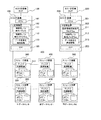
図1は、本発明の第1の実施の形態の計算機システムの構成を示すブロック図である。 FIG. 1 is a block diagram showing a configuration of a computer system according to the first embodiment of this invention.
第1の実施の形態の計算機システムは、ホスト計算機100、200、及び、ストレージ装置300、350、400、450、500、550によって構成されている。
The computer system according to the first embodiment includes
ホスト計算機100は、CPU101、メモリ、入出力装置、主記憶装置(ディスク)102及び入出力処理装置(IOP)103が備わるコンピュータ装置である。ホスト計算機200も、ホスト計算機100と同様の構成が備わっている。
The
ホスト計算機(正ホスト)100の主記憶装置102には、制御用I/O発行パラメータ111、制御用I/O発行プログラム112及びデータ多重化構成情報113(図2)が記憶されている。制御用I/O発行プログラム112は、CPU101によって実行され、ストレージ装置300、350に対して障害検知のための制御用I/O(例えば、ハートビートI/O)を発行する。
The
ホスト計算機(副ホスト)200の主記憶装置202には、更新情報反映指示プログラム211、制御用I/O監視プログラム212及びデータ多重化構成情報213(図2)が記憶されている。更新情報反映指示プログラム211は、CPU201によって実行され、更新情報反映プログラム418(図9)に対して、副更新情報記憶部417(図9)に含まれる更新情報の削除を指示する。制御用I/O監視プログラム212は、CPU201によって実行され、制御用I/O発行プログラム112によって発行された制御用I/Oを受信し、ストレージ装置300、400、500等の障害発生を、制御用I/Oの転送経路毎に監視する。
The
また、ホスト計算機100、200には、計算機システムの動作を監視する保守用端末装置(SVP:サービスプロセッサ)120、220が備わっている。
The
ストレージ装置300、350は、主データセンタに設けられており、ホスト計算機100と接続されることによって、ホスト計算機100からデータの入出力がされる。ストレージ装置300は、ディスク制御装置310及びディスクアレイ320が備わっており、ディスク制御装置310がディスクアレイ320へのデータの入出力を制御する。ストレージ装置350も、ストレージ装置300と同じ構成を有する。
The
ストレージ装置400、450は、主データセンタの比較的近くに設けられた副データセンタ1に設けられている。ストレージ装置400は、ストレージ装置300に接続され、ストレージ装置300からデータが転送される。また、ストレージ装置450は、ストレージ装置350に接続され、ストレージ装置350からデータが転送される。このデータ転送によって、主データセンタのストレージ装置300、350に記憶されるデータが、比較的短い間隔で、副データセンタ1のストレージ装置400、450にコピーされる。ストレージ装置400、450も、ストレージ装置300と同じ構成を有する。
The
ストレージ装置500、550は、主データセンタの遠隔地に設けられた副データセンタ2に設けられている。ストレージ装置500は、ストレージ装置400に接続され、ストレージ装置400からデータが転送される。また、ストレージ装置550は、ストレージ装置450に接続され、ストレージ装置450からデータが転送される。このデータ転送によって、副データセンタ1のストレージ装置400、450に記憶されるデータが、比較的長い間隔(主データセンタと副データセンタ1とのリモートコピーよりも長い間隔)で、副データセンタ2のストレージ装置500、550にコピーされる。ストレージ装置500、550も、ストレージ装置300と同じ構成を有する。
The
このようにして主データセンタ、副データセンタ1及び副データセンタ2が、複数の伝送経路で多段階にカスケード接続され、主データセンタと副データセンタ1との間のリモートコピー、及び副データセンタ1と副データセンタ2との間のリモートコピーが行われる。この同一の伝送経路内のストレージ装置は同じ構成を有することが望ましいが、別の伝送経路のストレージ装置同士は異なる構成でもよい。
In this way, the main data center, the
以上説明したリモートコピーには非同期コピーと同期コピーとがあり、本発明の実施の形態では、いずれのタイプのコピーも適用することができるが、望ましくは、主データセンタと副データセンタ1との間は同期コピーを行い、副データセンタ1と副データセンタ2との間は非同期コピーを行うとよい。
The remote copy described above includes an asynchronous copy and a synchronous copy, and any type of copy can be applied in the embodiment of the present invention. Preferably, the
なお、図1には、ストレージ装置が2経路で3段カスケード接続されている例を示したが、これと異なる経路数、段数であってもよい。 Although FIG. 1 shows an example in which the storage apparatus is cascade-connected with two paths in three stages, the number of paths and stages may be different from this.
ホスト計算機100(制御用I/O発行プログラム112)から送信された制御用I/O信号は、ストレージ装置300、400、500を経由してホスト計算機200(制御用I/O監視プログラム212)で受信されるか否かが監視される。同様に、ホスト計算機100(制御用I/O発行プログラム112)から送信された制御用I/O信号は、ストレージ装置350、450、550を経由してホスト計算機200(制御用I/O監視プログラム212)で受信されるか否かが監視される。
The control I / O signal transmitted from the host computer 100 (control I / O issue program 112) is transmitted to the host computer 200 (control I / O monitoring program 212) via the
そして、制御用I/Oの発行タイミングに対応して制御用I/Oが受信できなければ、そのデータ伝送経路(伝送線やスイッチ)や、その伝送経路上のストレージ装置に障害が発生していると判定できる。また、ホスト計算機100が、同じ拡張コピーグループのボリュームに対して同一のタイミングで制御用I/Oを発行すれば、ホスト計算機200(制御用I/O監視プログラム212)によって、いずれかの伝送経路を経由した制御用I/Oが受信できなければ、そのデータ伝送経路(伝送線やスイッチ)や、その伝送経路上のボリューム(ストレージ装置)に障害が発生していると判定できる。
If the control I / O cannot be received in response to the control I / O issuance timing, a failure has occurred in the data transmission path (transmission line or switch) or the storage device on the transmission path. Can be determined. Further, if the
図2は、第1の実施の形態のデータ多重化構成情報の構成図である。 FIG. 2 is a configuration diagram of data multiplexing configuration information according to the first embodiment.
データ多重化構成情報113、213は、各々ホスト計算機100、200の主記憶装置に記憶されており、いずれも、コピーグループ定義情報130(図3)、コピーグループ関連定義情報150(図5)及びストレージ装置構成情報160(図7)が含まれる。
The data
図3は、第1の実施の形態のコピーグループ定義情報の構成図である。 FIG. 3 is a configuration diagram of copy group definition information according to the first embodiment.
コピーグループ定義情報130には、コピーグループ番号131、多重化処理種別識別子132、上流グループ番号133、下流グループ番号134、関連有無フラグ135及びペア情報140(図4)が含まれている。
The copy
コピーグループ番号131は、ユーザによって構成されたボリュームのペアの集合体であるコピーグループに付された番号である。コピーグループは、対となる二つのストレージ装置内のボリュームによって構成されている。
The
多重化処理種別識別子132には、当該コピーグループで用いられるコピーの種類が規定される。例えば、本実施の形態では、同期コピーか非同期コピーかが行われるので、このいずれかが規定される。
The multiplexing
上流グループ番号133及び下流グループ番号134は、コピーグループ(ストレージ装置)のカスケード構造を示す。具体的には、上流グループ番号133は、自コピーグループに対してコピー元となるコピーグループの番号である。なお、上流グループ番号133が「なし」の場合には、自コピーグループの上流にはコピー元となるストレージ装置が設けられておらず、ホスト計算機から直接当該コピーグループのペア情報に記述されたコピー元ボリュームに対してデータが書き込まれていることを示す。また、下流グループ番号134は、自コピーグループに対してコピー先となるコピーグループの番号である。なお、下流グループ番号134が「なし」の場合には、自コピーグループの下流にはコピー先となるストレージ装置が設けられておらず、伝送経路の終端に位置する装置であることを示す。
The
関連有無フラグ135は、自コピーグループが拡張コピーグループに属しているか否かを示す。
The relation presence /
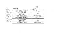
図4は、第1の実施の形態のペア情報の構成図である。 FIG. 4 is a configuration diagram of pair information according to the first embodiment.
ペア情報136は、コピー元ボリュームとコピー先ボリュームとの関係を表すもので、コピー元ボリューム番号141、コピー元ストレージ装置番号142、コピー元ボリュームシリアル番号143、コピー先ボリューム番号144、コピー先ストレージ装置番号145及びコピー先ボリュームシリアル番号146が含まれている。
The pair information 136 represents the relationship between the copy source volume and the copy destination volume. The copy
コピー元ストレージ装置番号142は、コピー元ボリューム番号141に示されるボリュームが属するストレージ装置の番号である。コピー先ストレージ装置番号145は、コピー先ボリューム番号144に示されるボリュームが属するストレージ装置の番号である。
The copy source
ボリュームシリアル番号143、146は、ホストからのI/O発行に用いられる識別子である。
The volume
図5は、第1の実施の形態のコピーグループ関連定義情報の構成図である。 FIG. 5 is a configuration diagram of copy group related definition information according to the first embodiment.
コピーグループ関連定義情報150は、コピーグループと拡張コピーグループとの関係を規定するもので、拡張コピーグループ番号と、当該拡張コピーグループに属しているコピーグループの番号が規定されている。具体的には図10に示す場合には、拡張コピーグループ「01」には、コピーグループ「01」及びコピーグループ「05」が含まれている。
The copy group
なお、前述したように、コピーグループは、対となる二つのストレージ装置内のボリュームによって構成されており、同一段階の複数のストレージ装置に跨ることはないが、拡張コピーグループは、コピーグループの集合体であり、同一段階の複数のストレージ装置(例えば、他の伝送経路のストレージ装置)を含んで定義することができる。 As described above, a copy group is composed of volumes in two paired storage devices and does not span multiple storage devices at the same stage, but an extended copy group is a set of copy groups. It can be defined to include a plurality of storage devices at the same stage (for example, storage devices of other transmission paths).
図6は、第1の実施の形態の制御用I/O発行パラメタの構成図である。 FIG. 6 is a configuration diagram of a control I / O issue parameter according to the first embodiment.
制御用I/O発行パラメタ111には、拡張コピーグループ毎に、制御用I/Oの発行タイミングとして、ホスト計算機100からハートビートI/Oを何秒毎に発行するかが規定されている。制御用I/O発行パラメタ111は、ホスト計算機SVP120から入力したり、副側のホスト計算機SVP220から図示しないネットワークを介して入力することができるが、他の装置から入力された情報の転送を受けて設定してもよい。
In the control I /
図7は、第1の実施の形態のストレージ装置構成情報の構成図である。 FIG. 7 is a configuration diagram of storage device configuration information according to the first embodiment.
ストレージ装置構成情報160には、データセンタ毎にストレージ装置の構成が規定されている。具体的には、主データセンタには装置番号「1」のストレージ装置と、装置番号「2」のストレージ装置とが設けられている。また、装置番号「1」のストレージ装置には、ボリューム番号「01」のボリューム、ボリューム番号「02」のボリューム、及びボリューム番号「03」のボリュームが設けられており、各ボリュームのボリュームシリアル番号も記録されている。さらに、他のデータセンタ、ストレージ装置及びボリュームについても同様にそれらの関係が規定されている。
The storage
図8は、第1の実施の形態のホスト計算機100によって発行されるI/Oの構成図である。
FIG. 8 is a configuration diagram of I / O issued by the
ホスト計算機100は、ストレージ装置300、350に対して、ライト要求600を発行する。ライト要求600には、ライト時刻601及びライト情報602が含まれている。
The
ライト時刻601は、ホスト計算機100から当該ライト要求600が発行された時刻を示すタイムスタンプであり、ホスト計算機100がストレージ装置300等にライト要求600を発行するときに付与される。ライト情報602は、ストレージ装置300に書き込まれるデータそのもの、書き込まれるデータ長、及び書き込み対象のボリューム番号とアドレスによって構成されている。
The
また、ライト情報602には、当該ライト要求600が制御用I/Oか否かを判定する識別子を格納する制御用I/O識別子領域603が設けられている。例えば、制御用I/O識別子領域603に「0」が格納されている場合は、ライト要求600は通常I/Oである。一方、制御用I/O識別子領域603に「0」以外の値が格納されている場合は、ライト要求600は制御用I/Oである。ライト要求600は制御用I/Oである場合に、制御用I/O識別子領域603に格納される値は、1〜5のシーケンス番号を1回の制御用I/O発行毎に順番に利用して(ラウンドロビンさせて)記入するとよい。
The
また、ライト情報602には、当該ライト要求600をどのボリュームのどこに書き込むかを示すデータ書込位置604が設けられている。
Also, the
ホスト計算機100は、ライト要求600を発行し、ライト要求600をストレージ装置300等へ送信する。ライト要求のうち制御用I/Oは、ライトデータをボリューム321等に格納するためではなく、副データセンタのストレージ装置400、450等の障害を検出するために発行されるI/Oである。よって、ライト情報602の制御用識別子603以外の情報は意味のないダミーデータである。従って、第1の実施の形態では、制御用I/Oから、データ書込位置604等の無用な情報は省略してもよい。すなわち、制御用I/Oは、いわばダミーのライト要求である。
The
なお、この制御用I/Oに、ストレージ装置に実際に書き込まれるデータを含めて、ストレージ装置に対してデータを書き込むと共に、障害を検知するようにしてもよい。 The control I / O may include data that is actually written to the storage device, data may be written to the storage device, and a failure may be detected.
図9は、第1の実施の形態のストレージ装置の構成を示すブロック図である。図9には、ストレージ装置400の構成を例示するが、他のストレージ装置300、350、450、500、550も同じ構成を有する。
FIG. 9 is a block diagram illustrating a configuration of the storage apparatus according to the first embodiment. FIG. 9 illustrates the configuration of the
ストレージ装置400等は、ディスク制御装置410及びディスクアレイ420によって構成されている。
The
ディスク制御装置410には、CPU、メモリ及びインターフェースが設けられている。メモリには制御プログラムが記憶されており、CPUが制御プログラムを実行することによって、ホスト計算機100等の計算機又は他のストレージ装置からの要求に基づいてディスクアレイ420に対するデータの入出力を制御する。また、メモリには、ディスクアレイ420に入出力されるデータを一時的に記憶するキャッシュが設けられている。
The
ディスク制御装置410は、ストレージ装置400がコピー元となる場合に機能する正ライト要求受領プログラム411、更新情報送出プログラム412、正更新情報記憶部413、及び副ボリューム対応表414を有する。
The
正ライト要求受領プログラム411は、CPUによって実行され、ホスト計算機100によって発行されるライト要求を受信するライト要求受領処理(図12)を行う。すなわち、正ライト要求受領プログラム411は、ストレージ装置が主データセンタに設置され、ホスト計算機100と直接接続される場合(ストレージ装置300、350の場合)に機能する。
The primary write
更新情報送出プログラム412は、CPUによって実行され、リモートコピー対象のボリュームがストレージ装置400に存在するとき、正更新情報記憶部413に格納された更新情報を、更新情報に含まれるライト時刻601の古い順に(ライト要求600の発行順に)、コピー先ストレージ装置500に送る。ここで、更新情報は、ストレージ装置300がホストから受け取ったライト要求600に、コピー先の副ボリュームIDを付加した情報である(図12のS112)。
The update
正更新情報記憶部413は、ボリュームに反映した更新情報又は受信したライト命令から生成された更新情報が、更新情報に含まれるライト時刻601の古い順に(すなわち、ライト要求600の発行順に)格納される。
In the primary update
副ボリューム対応表414は、ライト情報602に含まれるデータ書込先ストレージ装置番号に対応するコピー先ストレージ装置番号を求める対応表である。
The secondary volume correspondence table 414 is a correspondence table for obtaining a copy destination storage device number corresponding to the data write destination storage device number included in the
さらに、ディスク制御装置410は、ストレージ装置がコピー先となる場合に機能する更新情報受領プログラム415、最新時刻報告プログラム416、副更新情報記憶部417及び更新情報反映プログラム418を有し、これらのプログラム415、416、418はCPUによって実行される。
Further, the
更新情報受領プログラム415は、更新情報に含まれるライト時刻601の古い順に(すなわち、ライト要求600の発行順に)、更新情報を副更新情報記憶部417に格納する。具体的には、接続されているコピー元ストレージ装置300から送られた更新情報を、更新情報に含まれるライト時刻601の古い順に並べて副更新情報記憶部417に格納し、コピー元ストレージ装置300に対して完了を報告する。
The update
最新時刻報告プログラム416は、更新情報反映指示プログラム211からの指示を受け、副更新情報記憶部417に格納されている更新情報のうち、最も新しい更新情報のライト時刻601を更新情報反映指示プログラム418に送信する。
The latest
副更新情報記憶部417は、コピー元ストレージ装置300から受信した更新情報が、更新情報に含まれるライト時刻601の古い順に(すなわち、ライト要求600の発行順に)格納される。
In the secondary update
更新情報反映プログラム418は、更新情報反映指示プログラム211からの指示に基づいて、副更新情報記憶部417に含まれる更新情報のうち、指示された基準時刻以前のライト時刻601を持つ更新情報をボリュームに反映し、反映した更新情報を副更新情報記憶部417から削除する。
Based on an instruction from the update information
ホスト計算機100からストレージ装置300にライト要求600が発行されると、ライト要求600に含まれるライト時刻601及びライト情報602が抽出される。ストレージ装置300は、ライト時刻601を用いて、複数のライト要求600を時間順に並べることができる。ホスト計算機100が複数設けられている場合でも、(例えば共通のタイムサーバを用いて)時刻情報を共通化することによって、異なるホスト計算機100から発行されたライト要求600も時間順に並べることができる。
When the
ディスクアレイ420は、複数の物理的ディスクドライブによって構成されている。ディスクドライブには、OSが単一のディスクとして認識できる単位である論理ボリュームが設定されている。また、論理ボリュームはRAID(Redundant Array of Independent Disks)によって構成されており、同時に複数のディスクドライブにデータを読み書きすることによって、ディスクへのアクセスを高速化し、また、データに冗長性を持たせて記憶している。このため、ディスクドライブの一部に障害が生じても、記憶されたデータが消失しないようになっている。なお、論理ボリュームは、それぞれがRAIDのようなディスクアレイ(複数の記憶装置の集合体)であっても、一つのディスクドライブであっても、単独又は複数の記憶装置の一部であってもよい。
The
また、ストレージ装置400には、計算機システムの動作を監視する保守用端末装置(SVP:サービスプロセッサ)430が備わっている。
Further, the
図10は、第1の実施の形態のリモートコピー処理の概念図である。 FIG. 10 is a conceptual diagram of remote copy processing according to the first embodiment.
主データセンタの装置番号「1」のストレージ装置300は、ボリューム「01」、ボリューム「02」、及びボリューム「03」によって構成されている。副データセンタ1の装置番号「5」のストレージ装置400は、ボリューム「11」、ボリューム「12」、及びボリューム「13」によって構成されている。
The
ストレージ装置300の各ボリュームは、ストレージ装置400の各ボリュームとペアを構成しており、これらのボリュームでコピーグループ「01」が構成されている。すなわち、ボリューム「01」、「02」、「03」に記憶されたデータは、ボリューム「11」、「12」、「13」にコピーされる。
Each volume of the
また、主データセンタの装置番号「2」のストレージ装置350は、ボリューム「05」、ボリューム「06」、及びボリューム「07」によって構成されている。副データセンタ1の装置番号「8」のストレージ装置450は、ボリューム「15」、ボリューム「16」、及びボリューム「17」によって構成されている。
In addition, the
ストレージ装置350のボリューム「05」は、ストレージ装置450のボリューム「15」とペアを構成しており、これらのボリュームでコピーグループ「05」が構成されている。また、ストレージ装置350のボリューム「06」、「07」は、装置番号「8」のストレージ装置450のボリューム「16」、「17」と各々ペアを構成しており、これらのボリュームでコピーグループ「09」が構成されている。すなわち、ボリューム「05」、「06」、「07」に記憶されたデータは、ボリューム「15」、「16」、「17」にコピーされるが、これらのボリュームは、異なるコピーグループに属する。
The volume “05” of the
同様に、副データセンタ1のストレージ装置400、450のボリュームと、副データセンタ2のストレージ装置500、550のボリュームとはペアを構成しており、コピーグループ、拡張コピーグループが構成されている。
Similarly, the volumes of the
図11は、第1の実施の形態の制御用I/O発行処理のフローチャートであり、制御用I/O発行プログラム112によって実行される。
FIG. 11 is a flowchart of the control I / O issue process according to the first embodiment, which is executed by the control I /
まず、制御用I/O発行パラメタを参照して、処理すべきコピーグループの発行インターバル情報を取得する(S101)。そして、コピーグループ関連定義情報130のペア情報140を参照して、処理対象のコピーグループに属するペアのコピー元ストレージ装置番号とコピー先ストレージ装置番号を全て取得する(S102)。そして、装置番号を取得したストレージ装置毎に、コピーグループ定義情報130のペア情報140に記述されたボリュームを選択し、選択されたボリュームに対して制御用I/O識別子領域603に「0」を格納した制御用I/Oを発行する(S103)。
First, the issue interval information of the copy group to be processed is acquired with reference to the control I / O issue parameter (S101). Then, with reference to the
その後、制御用I/O発行停止要求を監視する(S104)。このとき、SVP120から入力された制御用I/O発行停止要求を受信すると、この処理を終了する(S106)。一方、制御用I/O発行停止要求を受信しなければ、次の制御用I/O発行処理の起動タイミングまで待機して、ステップS102に戻る(S105)。
Thereafter, the control I / O issuance stop request is monitored (S104). At this time, when the control I / O issuance stop request input from the
図12は、第1の実施の形態のライト要求受領処理のフローチャートであり、正ライト要求受領プログラム411によって実行される。
FIG. 12 is a flowchart of the write request reception process according to the first embodiment, which is executed by the primary write
ホスト計算機100からのライト要求600を受信すると、受信したライト要求600中のライト情報602に含まれるボリュームIDを抽出し、副ボリューム対応表414を参照して、ライト情報602で指定されたデータ書込先ボリュームに対応する副ボリュームIDを取得する(S111)。
When the
次に、取得した副ボリュームIDをライト要求600に付加して、更新情報を作成する(S112)。次に、更新情報に含まれるライト時刻601の古い順に、作成した更新情報を並べて、正更新情報記憶部413に格納する(S113)。
Next, update information is created by adding the acquired secondary volume ID to the write request 600 (S112). Next, the created update information is arranged in order from the
次に、ライト要求600が制御用I/Oであるか否かを判定する(S114)。ライト要求600の制御用I/O識別子領域603が「0」でなければ、当該ライト要求は制御用I/Oなので、ボリュームに対してデータを書き込む必要がないと判定し、ステップS116に移行する。
Next, it is determined whether or not the
一方、ライト要求600の制御用I/O識別子領域603が「0」であれば、当該ライト要求は制御用I/Oではないので(通常I/Oなので)、ライト要求600によって指示されたボリュームに対してデータを書き込む(S115)。
On the other hand, if the control I /
その後、ホスト計算機100に対してライト要求600が完了したことを報告する。
Thereafter, the
このように、正更新情報記憶部413には、ライト要求600の発行順に、ライト要求600に対応する更新情報が格納される。
Thus, the update information corresponding to the
図13は、第1の実施の形態の更新情報送出処理のフローチャートであり、更新情報送出プログラム412によって実行される。
FIG. 13 is a flowchart of update information transmission processing according to the first embodiment, which is executed by the update
まず、更新情報に含まれるライト時刻601が古い順に、正更新情報記憶部413から更新情報を読み出す(S121)。そして、読み出した更新情報を、接続されたコピー先ストレージ装置に送信する(S122)。その後、コピー先ストレージ装置から完了報告が返信されてくるのを待つ(S123)。コピー先ストレージ装置からの完了報告を受信すると、正更新情報記憶部413から読み出した更新情報を削除し(S124)、ステップS121に戻る。
First, the update information is read from the correct update
このように、正更新情報記憶部413に格納された更新情報は、更新情報に含まれるライト時刻601の古い順に(すなわち、ライト要求600の発行順に)、コピー先副ストレージ装置に送られる。
In this manner, the update information stored in the primary update
図14は、第1の実施の形態の更新情報反映処理のフローチャートであり、更新情報反映プログラム418によって実行される。
FIG. 14 is a flowchart of the update information reflection process according to the first embodiment, which is executed by the update
更新情報反映処理では、副更新情報記憶部417に格納されている更新情報のうち、制御用I/O識別子領域603を参照して、制御用I/Oであるかを判断する(S130)。その判定の結果、制御用I/Oである場合は、更新情報はボリュームに反映されない。一方、制御用I/Oでない場合は、指示された基準時刻以前のライト時刻601を有する更新情報をボリュームに反映する(S131)。
In the update information reflection process, the control information I /
そして、ステップS131でボリュームに反映した更新情報を、副更新情報記憶部417から削除する(S132)。 Then, the update information reflected in the volume in step S131 is deleted from the secondary update information storage unit 417 (S132).
図15は、第1の実施の形態の制御用I/O監視処理のフローチャートであり、制御用I/O監視プログラム212によって実行される。
FIG. 15 is a flowchart of the control I / O monitoring process according to the first embodiment, which is executed by the control I /
まず、コピーグループ定義情報130から求めたグループ内の各ディスク毎に、制御用I/Oが到着しているかを監視する(S141)。その結果、グループ内のすべてのディスクに制御用I/Oが到着していれば、更新情報をボリュームに反映する(S146)。 First, it is monitored whether the control I / O has arrived for each disk in the group obtained from the copy group definition information 130 (S141). As a result, if the control I / O has arrived at all the disks in the group, the update information is reflected in the volume (S146).
一方、グループ内のいずれかのディスクに制御用I/Oが到着しなければ、到着していない制御用I/Oの伝送経路であるディスク群の状態情報を問い合わせ、これらのストレージ装置の状態情報を取得して、障害ペアを特定する(S143)。各ストレージ装置は接続されているストレージ装置の状態(サスペンドか、デュープレックスか)の情報を保有しているので、下流側から順にストレージ装置の状態を問い合わせることによって、どのストレージ装置が障害状態で停止しているかの情報を取得することができる。なお、このとき、障害箇所の他に、障害原因を特定してもよい。 On the other hand, if the control I / O does not arrive at any of the disks in the group, the status information of the disk group that is the transmission path of the control I / O that has not arrived is inquired. And a failure pair is specified (S143). Each storage device holds information on the status of the connected storage device (suspended or duplexed). By inquiring the status of the storage device in order from the downstream side, which storage device stops in a faulty state. You can get information about what you are doing. At this time, in addition to the fault location, the cause of the fault may be specified.
そして、コピーグループ定義情報130を参照して、障害箇所のペアが属するグループ内の他のペアの情報を取得し、当該グループ内のディスクに対してサスペンドを指示する(S144)。そして、更新情報反映プログラム418に対して、該当するコピーグループの更新情報反映処理の停止を指示する(S145)。このようにして、障害発生箇所として特定されたストレージ装置に対応する、他の伝送経路のストレージ装置が行う処理が停止する。なお、ストレージ装置が行う処理を停止することなく、ストレージ装置間のデータ送受信(データコピー)を停止してもよい。
Then, with reference to the copy
以上説明したように、従来のリモートコピーでは、ストレージ装置を監視するために、各ストレージ装置にハートビート信号を短い間隔で送信すると、ストレージ装置を監視するサーバの負荷が大きくなり、通常のI/Oの処理に遅延が生じてしまう。特に、第1の実施の形態のようにディスク装置が多段にカスケード接続される場合には、全てのハートビート信号が最初に接続されるディスク装置300、350を経由することから、これらのディスク装置にI/O負荷が集中する。すなわち、従来技術では、最初に接続されるディスク装置より先のペア情報(1個の状態情報取得は、書き込みと読み出しの1対が必要)も、最初に接続されるディスク装置経由で取得するために、I/O負荷が特定のディスク装置に集中する。
As described above, in conventional remote copy, if a heartbeat signal is transmitted to each storage device at a short interval in order to monitor the storage device, the load on the server that monitors the storage device increases, and the normal I / O A delay occurs in the processing of O. In particular, when the disk devices are cascaded in multiple stages as in the first embodiment, all the heartbeat signals go through the
一方、ハートビート信号による負荷を軽減するために、ハートビート信号の送信間隔を長くすると、障害発生の検出が遅れてしまう。特に、第1の実施の形態のように複数のストレージ装置が並列的に接続される場合に、一部のストレージ装置に障害が発生したときでも、他のストレージ装置のサスペンドが遅れてしまい、サスペンドが発生しなかったストレージ装置ではデータコピーが続くことから、データの整合性が破綻する。 On the other hand, if the heartbeat signal transmission interval is increased in order to reduce the load caused by the heartbeat signal, the detection of the occurrence of a failure is delayed. In particular, when a plurality of storage devices are connected in parallel as in the first embodiment, even if some storage devices fail, the suspension of other storage devices is delayed, and Since the data copy continues in the storage apparatus in which no data has occurred, the data consistency is broken.
しかし、第1の実施の形態では、カスケード接続されたストレージ装置300等に対して、ホスト計算機100から制御用I/Oを送ることによって、ストレージ装置の負荷の増大を抑制しつつ、ストレージ装置の障害を監視することができる。さらに、障害発生時に、コピー先のストレージ装置との整合性を保ちつつ、未更新データが過剰に蓄積されることを防止できる。
However, in the first embodiment, by sending control I / O from the
次に、本発明の第2の実施の形態について説明する。 Next, a second embodiment of the present invention will be described.
第2の実施の形態の計算機システムは、第1の実施の形態の計算機システムと異なり、ストレージ装置のボリュームに制御用I/O書込部が設けられている点が異なる。なお、前述した第1の実施の形態と同じ構成には同じ符号を付し、その詳細な説明は省略する。 The computer system according to the second embodiment is different from the computer system according to the first embodiment in that a control I / O writing unit is provided in the volume of the storage apparatus. In addition, the same code | symbol is attached | subjected to the same structure as 1st Embodiment mentioned above, and the detailed description is abbreviate | omitted.
図16は、本発明の第2の実施の形態の計算機システムの構成を示すブロック図である。 FIG. 16 is a block diagram illustrating a configuration of a computer system according to the second embodiment of this invention.
第2の実施の形態では、ストレージ装置300等のボリューム321等に制御用I/O書込部322等が設けられている。また、第2の実施の形態では、制御用I/Oに制御用I/O識別子領域603を設けることは必ずしも必要ない。データ書込位置604によって、制御用I/O書込部322の位置を示している。従って、正ホスト計算機100から発行される通常のI/O及び制御用I/Oの双方とも、前述した第1の実施の形態のライト要求600(図8)から制御用I/O識別子領域603を除いた構成とすればよい。
In the second embodiment, a control I /
第2の実施の形態においても、第1の実施形態と同様に、正ホスト計算機100からストレージ装置300に対して制御用I/Oが発行される。しかし、第2の実施の形態では、正ホスト計算機100は、制御用I/Oに含まれる書き込みデータが、ボリューム321内に設けられた制御用I/O書込部322に格納されるように、ライト要求にデータ書込位置604が設定された制御用I/Oを発行する。この制御用I/O書込部322に書き込まれる制御用I/Oには、ライト時刻601及び制御用I/Oが識別可能なシーケンス番号が含まれていればよい。
Also in the second embodiment, a control I / O is issued from the
従って、ストレージ装置300は、第1の実施の形態の更新情報反映処理と異なり、制御用I/O更新情報か否かの判定処理(図14のS130)を実行しない。すなわち、ストレージ装置300は、制御用I/Oに設定されたデータ書込位置604を参照し、このデータ書込位置604に示されたボリュームに設けられたデータ書込位置(制御用I/O書込部322)に、制御用I/Oを格納する。
Therefore, unlike the update information reflection process of the first embodiment, the
このように第2の実施の形態では、ホスト計算機100及び上位ストレージ装置(コピー元ストレージ装置)からの制御用I/Oが、制御用I/O書込部422に書き込まれる。これにより受信したI/Oが通常I/Oか、制御用I/Oかの振り分け処理(図12のS114)が不要となり、ストレージ装置の処理負荷の増大を抑制することができる。
As described above, in the second embodiment, control I / O from the
100 ホスト計算機(正ホスト)
111 制御用I/O発行パラメタ
112 制御用I/O発行プログラム
113 データ多重化構成情報
200 ホスト計算機(副ホスト)
211 更新情報反映指示プログラム
212 制御用I/O監視プログラム
213 データ多重化構成情報
300、350 ストレージ装置(主データセンタ)
400、450 ストレージ装置(副データセンタ1)
500、550 ストレージ装置(副データセンタ2)
100 Host computer (primary host)
111 Control I /
211 Update information
400, 450 storage device (sub data center 1)
500, 550 storage device (sub data center 2)
Claims (16)
前記第1ストレージ装置と接続され、前記第1ストレージ装置に記憶されるデータの複製を記憶する第2ストレージ装置と、
前記第2ストレージ装置と接続され、前記第2ストレージ装置に記憶されるデータの複製を記憶する第3ストレージ装置と、
前記第1計算機と接続され、通常運用に供される第4ストレージ装置と、
前記第4ストレージ装置と接続され、前記第4ストレージ装置に記憶されるデータの複製を記憶する第5ストレージ装置と、
前記第5ストレージ装置と接続され、前記第5ストレージ装置に記憶されるデータの複製を記憶する第6ストレージ装置と、
前記第3ストレージ装置及び前記第6ストレージ装置と接続される第2計算機とを含み、
前記第1計算機から、前記第1ストレージ装置、前記第2ストレージ装置及び前記第3ストレージ装置を経由して前記第2計算機に至る第1伝送経路と、前記第1計算機から、前記第4ストレージ装置、前記第5ストレージ装置及び前記第6ストレージ装置を経由して前記第2計算機に至る第2伝送経路とを備え、
前記第1計算機及び前記第2計算機の各々は、制御プログラムが記憶されるメモリと、前記制御プログラムを実行することによって前記各ストレージ装置へのデータ入出力を制御する制御部と、前記各ストレージ装置との間でデータや制御信号を送受信する入出力処理装置とを有する計算機システムであって、
前記第1計算機は、前記第1伝送経路及び前記第2伝送経路に対して制御用I/Oを送信し、
前記各ストレージ装置は、受信した制御用I/Oを、接続されている他のストレージ装置又は第2計算機に転送し、
前記第2計算機は、
前記第1伝送経路によって転送される制御用I/O、及び前記第2伝送経路によって転送される制御用I/Oを監視し、
前記制御用I/Oが転送されない伝送経路があれば、該伝送経路に含まれるストレージ装置に対して状態情報の取得を要求し、
該取得した状態情報に基づいて障害発生箇所として特定されたストレージ装置に対応する、他の伝送経路のストレージ装置の停止を要求する計算機システム。 A first storage device connected to the first computer and used for normal operation;
A second storage device connected to the first storage device and storing a copy of data stored in the first storage device;
A third storage device connected to the second storage device and storing a copy of data stored in the second storage device;
A fourth storage device connected to the first computer and used for normal operation;
A fifth storage device connected to the fourth storage device and storing a copy of data stored in the fourth storage device;
A sixth storage device connected to the fifth storage device and storing a copy of data stored in the fifth storage device;
A second computer connected to the third storage device and the sixth storage device,
A first transmission path from the first computer to the second computer via the first storage device, the second storage device, and the third storage device; and from the first computer to the fourth storage device. A second transmission path to the second computer via the fifth storage device and the sixth storage device,
Each of the first computer and the second computer includes a memory in which a control program is stored, a control unit that controls data input / output to each storage device by executing the control program, and each storage device A computer system having an input / output processing device for transmitting and receiving data and control signals to and from
The first computer transmits control I / O to the first transmission path and the second transmission path,
Each of the storage devices transfers the received control I / O to another connected storage device or second computer,
The second computer is
Monitoring the control I / O transferred by the first transmission path and the control I / O transferred by the second transmission path;
If there is a transmission path to which the control I / O is not transferred, the storage apparatus included in the transmission path is requested to obtain status information,
A computer system that requests to stop a storage device on another transmission path corresponding to a storage device identified as a failure occurrence location based on the acquired status information.
前記第1計算機及び前記第2計算機は、制御プログラムが記憶されるメモリと、前記制御プログラムを実行することによって前記各ストレージ装置へのデータ入出力を制御する制御部と、前記各ストレージ装置との間でデータや制御信号を送受信する入出力処理装置とを有する計算機システムであって、
前記多段に接続された複数のストレージ装置は、
前記第1計算機から、第1のコピーグループを経由して前記第2計算機に至る第1伝送経路と、
前記第1計算機から、第2のコピーグループを経由して前記第2計算機に至る第2伝送経路と、を構成し、
前記第1計算機は、前記第1伝送経路第1を構成する第1のコピーグループ及び前記第2伝送経路を構成する第2のコピーグループに対して制御用I/Oをそれそれ送信し、
前記第1のコピーグループ及び前記第2のコピーグループの各ストレージ装置は、受信した制御用I/Oを、接続されている他のストレージ装置又は第2計算機に転送し、
前記第2計算機は、
前記第1伝送経路によって転送される制御用I/O、及び前記第2伝送経路によって転送される制御用I/Oを監視し、
前記制御用I/Oが転送されない伝送経路があれば、該伝送経路に含まれるストレージ装置に対して状態情報の取得を要求し、
該取得した状態情報に基づいて障害発生箇所として特定されたストレージ装置に対応する、他の伝送経路のストレージ装置の停止を要求する計算機システム。 A plurality of storage devices connected in multiple stages between the first computer and the second computer;
The first computer and the second computer include a memory in which a control program is stored, a control unit that controls data input / output to each storage device by executing the control program, and each storage device. A computer system having an input / output processing device for transmitting and receiving data and control signals between them,
The plurality of storage devices connected in multiple stages are:
A first transmission path from the first computer via the first copy group to the second computer;
A second transmission path from the first computer to the second computer via a second copy group, and
Wherein the first computer, which was then transmits a control I / O to the second copy group constituting the first copy group and the second transmission path constituting the first the first transmission path,
Each storage device of the first copy group and the second copy group transfers the received control I / O to another connected storage device or second computer,
The second computer is
It said control I / O that will be transferred by the first transmission path, and the control I / O to be transferred by said second transmission path is monitored,
If there is a transmission path to which the control I / O is not transferred , the storage apparatus included in the transmission path is requested to obtain status information ,
A computer system that requests to stop a storage device on another transmission path corresponding to a storage device identified as a failure occurrence location based on the acquired status information .
複製データを供給するストレージ装置のコピー元ボリュームと、前記複製データを記憶するストレージ装置のコピー先ボリュームとによってコピーグループが構成されており、
前記制御用I/Oは、前記コピーグループを構成するコピー元ボリュームから、当該コピーグループのコピー先ボリュームに転送されることによって、前記各伝送経路を伝わる請求項2に記載の計算機システム。 Each storage device of the first copy group and the second copy group has a volume in which the I / O transmitted from the first computer is written,
A copy source volume of the storage device for supplying replicated data, a copy group by the copy destination volume of the storage device for storing the replicated data is configured,
The computer system according to claim 2, wherein the control I / O is transferred through the transmission paths by being transferred from a copy source volume constituting the copy group to a copy destination volume of the copy group.
前記第1計算機は、前記複数のコピー元ボリュームに対して制御用I/Oを送信し、
前記第2計算機は、前記コピーグループに属する各コピー先ボリュームに制御用I/Oが到着しているか否かを監視する請求項3に記載の計算機システム。 The first copy group and the second copy group include a plurality of the copy source volumes and a plurality of the copy destination volumes,
The first computer transmits control I / O to the plurality of copy source volumes,
4. The computer system according to claim 3, wherein the second computer monitors whether or not a control I / O has arrived at each copy destination volume belonging to the copy group.
前記第1計算機から送信されたI/Oが書き込まれるボリュームを有し、
受信したI/Oが通常のI/Oであれば、該I/Oを前記ボリュームに反映し、所定のタイミングで接続されている他のストレージ装置に転送し、
受信したI/Oが制御用I/Oであれば、該I/Oを前記ボリュームに反映することなく、接続されている次段のストレージ装置又は前記第2計算機に転送する請求項2に記載の計算機システム。 Each of the storage devices
A volume in which I / O transmitted from the first computer is written;
If the received I / O is a normal I / O, the I / O is reflected in the volume, transferred to another connected storage device at a predetermined timing,
3. If the received I / O is a control I / O, the I / O is transferred to the connected next-stage storage apparatus or the second computer without reflecting the I / O to the volume. Computer system.
前記ボリュームには、通常のI/Oが書き込まれる通常I/O書込領域と、制御用I/Oが書き込まれる制御用I/O書込領域とを備え、
前記第1計算機は、前記通常I/O書込領域に通常のI/Oを書き込み、前記制御用I/O書込領域に制御用I/Oを書き込む請求項2に記載の計算機システム。 Each of the storage devices has a volume in which I / O transmitted from the first computer is written,
The volume includes a normal I / O write area in which normal I / O is written, and a control I / O write area in which control I / O is written.
The computer system according to claim 2, wherein the first computer writes a normal I / O to the normal I / O write area and writes a control I / O to the control I / O write area.
制御プログラムが記憶されるメモリと、前記制御プログラムを実行することによって前記各ストレージ装置へのデータ入出力を制御する制御部と、前記各ストレージ装置との間でデータや制御信号を送受信する入出力処理装置とを有する副ホスト計算機であって、
前記多段に接続された複数のストレージ装置は、
前記正ホスト計算機から、第1のコピーグループを経由して前記副ホスト計算機に至る第1伝送経路と、
前記正ホスト計算機から、第2のコピーグループを経由して前記副ホスト計算機に至る第2伝送経路と、を構成し、
前記第1伝送経路を構成する第1のコピーグループ及び前記第2伝送経路を構成する第2のコピーグループの各ストレージ装置は、前記正ホスト計算機から受信した制御用I/Oを、接続されている他のストレージ装置又は副ホスト計算機に転送し、
前記副ホスト計算機は、
前記第1伝送経路によって転送される制御用I/O、及び前記第2伝送経路によって転送される制御用I/Oを監視し、
前記制御用I/Oが転送されない伝送経路があれば、該伝送経路に含まれるストレージ装置に対して状態情報の取得を要求し、
該取得した状態情報に基づいて障害発生箇所として特定されたストレージ装置に対応する、他の伝送経路のストレージ装置の停止を要求する副ホスト計算機。 Of the multiple storage devices connected in multiple stages to the primary host computer, it is connected to the final storage device,
A memory for storing a control program, a control unit for controlling data input / output to each storage device by executing the control program, and an input / output for transmitting / receiving data and control signals to / from each storage device A secondary host computer having a processing device,
The plurality of storage devices connected in multiple stages are:
A first transmission path from the primary host computer via the first copy group to the secondary host computer;
A second transmission path from the primary host computer to the secondary host computer via a second copy group, and
The storage devices of the first copy group constituting the first transmission path and the second copy group constituting the second transmission path are connected to the control I / O received from the primary host computer. Transfer to another storage device or secondary host computer
The secondary host computer
Monitoring the control I / O transferred by the first transmission path and the control I / O transferred by the second transmission path ;
If there is a transmission path to which the control I / O is not transferred , the storage apparatus included in the transmission path is requested to obtain status information ,
A secondary host computer that requests the storage apparatus of another transmission path corresponding to the storage apparatus identified as the failure occurrence location based on the acquired status information .
複製データを供給するストレージ装置のコピー元ボリュームと、前記複製データを記憶するストレージ装置のコピー先ボリュームとによって前記第1及び第2のコピーグループが構成されており、
前記制御用I/Oは、前記第1及び第2のコピーグループを構成するコピー元ボリュームから、当該コピーグループのコピー先ボリュームにそれぞれ転送されることによって、前記各伝送経路を伝わる請求項9に記載の副ホスト計算機。 Before SL each storage device has a volume that the control I / O sent from the primary host computer is written,
A copy source volume of the storage device for supplying replicated data, wherein the first and second copy group by the copy destination volume of the storage device for storing the replicated data is configured,
Said control I / O from the copy source volumes constituting the first and second copy group, by being transferred respectively to the copy destination volume of the copy group, to claim 9 traveling through the respective transmission paths Described secondary host computer.
副ホスト計算機は、前記第1及び第2のコピーグループに属する各コピー先ボリュームに、前記正ホスト計算機によって送信された制御用I/Oが到着しているか否かを監視する請求項9に記載の副ホスト計算機。 The first and second copy groups include a plurality of the copy source volumes and a plurality of the copy destination volumes,
The secondary host computer monitors whether or not the control I / O transmitted by the primary host computer has arrived at each copy destination volume belonging to the first and second copy groups. Secondary host computer.
前記多段に接続された複数のストレージ装置は、
前記第1計算機から、第1のコピーグループを経由して前記第2計算機に至る第1伝送経路と、
前記第1計算機から、第2のコピーグループを経由して前記第2計算機に至る第2伝送経路と、を構成し、
前記第1計算機から送信され、前記第1伝送経路によって転送される制御用I/O、及び前記第2伝送経路によって転送される制御用I/Oを監視する第1手順と、
前記制御用I/Oが転送されない伝送経路があれば、該伝送経路に含まれるストレージ装置に対して状態情報の取得を要求する第2手順と、
該取得した状態情報に基づいて障害発生箇所として特定されたストレージ装置に対応する、他の伝送経路のストレージ装置の停止を要求する第3の手順を含むプログラム。 Provided in a computer system having a plurality of storage devices connected in multiple stages between a first computer and a second computer, a memory for storing a control program, and each storage device by executing the control program A program for causing a second computer having a control unit for controlling data input / output to / from the storage unit and an input / output processing device for transmitting / receiving data and control signals to / from each storage device to execute the following procedure: ,
The plurality of storage devices connected in multiple stages are:
A first transmission path from the first computer via the first copy group to the second computer;
A second transmission path from the first computer to the second computer via a second copy group, and
A first procedure for monitoring the control I / O transmitted from the first computer and transferred by the first transmission path , and the control I / O transferred by the second transmission path ;
If there is a transmission path to which the control I / O is not transferred, a second procedure for requesting the storage apparatus included in the transmission path to obtain status information ;
A program including a third procedure for requesting stop of a storage apparatus on another transmission path corresponding to a storage apparatus identified as a failure occurrence location based on the acquired status information .
複製データを供給するストレージ装置のコピー元ボリュームと、前記複製データを記憶するストレージ装置のコピー先ボリュームとによって前記第1及び第2のコピーグループが構成されており、
前記制御用I/Oは、前記第1及び第2のコピーグループを構成するコピー元ボリュームから、当該コピーグループのコピー先ボリュームに転送されることによって、前記各伝送経路を伝わる前記計算機システムに設けられる第2計算機に以下の手順を実行させるためのプログラムであって、
前記第1手順は、前記前記第1及び第2のコピーグループに属する各コピー先ボリュームに、前記第1計算機によって送信された制御用I/Oが到着しているか否かを監視し、
前記第2手順は、前記制御用I/Oが、当該コピーグループ内のいずれかのコピー先ボリュームに到着していなければ、当該到着していない制御用I/Oの伝送経路に含まれる各ストレージ装置に対して状態情報を要求する請求項14に記載のプログラム。 Each storage device has a volume to which control I / O transmitted from the first computer is written,
A copy source volume of the storage device for supplying replicated data, wherein the first and second copy group by the copy destination volume of the storage device for storing the replicated data is configured,
The control I / O is provided in the computer system that is transmitted through the respective transmission paths by being transferred from the copy source volume constituting the first and second copy groups to the copy destination volume of the copy group. A program for causing a second computer to execute the following procedure:
The first procedure monitors whether or not the control I / O transmitted by the first computer has arrived at each copy destination volume belonging to the first and second copy groups,
In the second procedure, if the control I / O has not arrived at any copy destination volume in the copy group, each storage included in the transmission path of the control I / O that has not arrived. The program according to claim 14, which requests status information from a device.
Priority Applications (2)
| Application Number | Priority Date | Filing Date | Title |
|---|---|---|---|
| JP2004232042A JP4401895B2 (en) | 2004-08-09 | 2004-08-09 | Computer system, computer and its program. |
| US10/964,761 US7441145B2 (en) | 2004-08-09 | 2004-10-15 | Failure monitoring for storage systems constituting multiple stages |
Applications Claiming Priority (1)
| Application Number | Priority Date | Filing Date | Title |
|---|---|---|---|
| JP2004232042A JP4401895B2 (en) | 2004-08-09 | 2004-08-09 | Computer system, computer and its program. |
Publications (3)
| Publication Number | Publication Date |
|---|---|
| JP2006048578A JP2006048578A (en) | 2006-02-16 |
| JP2006048578A5 JP2006048578A5 (en) | 2007-02-01 |
| JP4401895B2 true JP4401895B2 (en) | 2010-01-20 |
Family
ID=35758898
Family Applications (1)
| Application Number | Title | Priority Date | Filing Date |
|---|---|---|---|
| JP2004232042A Expired - Fee Related JP4401895B2 (en) | 2004-08-09 | 2004-08-09 | Computer system, computer and its program. |
Country Status (2)
| Country | Link |
|---|---|
| US (1) | US7441145B2 (en) |
| JP (1) | JP4401895B2 (en) |
Families Citing this family (52)
| Publication number | Priority date | Publication date | Assignee | Title |
|---|---|---|---|---|
| JP4835249B2 (en) * | 2006-04-26 | 2011-12-14 | 株式会社日立製作所 | Storage system, remote copy, and management method |
| US7702953B2 (en) * | 2007-01-04 | 2010-04-20 | International Business Machines Corporation | Storage management in cascaded replication of data |
| US7793148B2 (en) * | 2007-01-12 | 2010-09-07 | International Business Machines Corporation | Using virtual copies in a failover and failback environment |
| US7904682B2 (en) * | 2007-07-19 | 2011-03-08 | International Business Machines Corporation | Copying writes from primary storages to secondary storages across different networks |
| US7822892B2 (en) * | 2007-07-19 | 2010-10-26 | International Business Machines Corporation | Managing the copying of writes from primary storages to secondary storages across different networks |
| US7770073B2 (en) * | 2007-07-27 | 2010-08-03 | International Business Machines Corporation | Apparatus, system, and method for responsive acquisition of remote debug data |
| JP4982304B2 (en) * | 2007-09-04 | 2012-07-25 | 株式会社日立製作所 | Storage system that understands the occurrence of power failure |
| JP4810585B2 (en) * | 2009-05-11 | 2011-11-09 | 株式会社日立製作所 | Calculator that supports remote scan |
| JP5663950B2 (en) * | 2010-05-19 | 2015-02-04 | 富士通株式会社 | Connection expansion device and storage system |
| US8533539B2 (en) * | 2010-09-17 | 2013-09-10 | Symantec Corporation | Fault handling systems and methods |
| US10877898B2 (en) | 2017-11-16 | 2020-12-29 | Alibaba Group Holding Limited | Method and system for enhancing flash translation layer mapping flexibility for performance and lifespan improvements |
| US10496548B2 (en) | 2018-02-07 | 2019-12-03 | Alibaba Group Holding Limited | Method and system for user-space storage I/O stack with user-space flash translation layer |
| WO2019222958A1 (en) | 2018-05-24 | 2019-11-28 | Alibaba Group Holding Limited | System and method for flash storage management using multiple open page stripes |
| WO2020000136A1 (en) | 2018-06-25 | 2020-01-02 | Alibaba Group Holding Limited | System and method for managing resources of a storage device and quantifying the cost of i/o requests |
| US10921992B2 (en) | 2018-06-25 | 2021-02-16 | Alibaba Group Holding Limited | Method and system for data placement in a hard disk drive based on access frequency for improved IOPS and utilization efficiency |
| US10996886B2 (en) | 2018-08-02 | 2021-05-04 | Alibaba Group Holding Limited | Method and system for facilitating atomicity and latency assurance on variable sized I/O |
| US11327929B2 (en) | 2018-09-17 | 2022-05-10 | Alibaba Group Holding Limited | Method and system for reduced data movement compression using in-storage computing and a customized file system |
| US10977122B2 (en) | 2018-12-31 | 2021-04-13 | Alibaba Group Holding Limited | System and method for facilitating differentiated error correction in high-density flash devices |
| US11061735B2 (en) | 2019-01-02 | 2021-07-13 | Alibaba Group Holding Limited | System and method for offloading computation to storage nodes in distributed system |
| US11132291B2 (en) | 2019-01-04 | 2021-09-28 | Alibaba Group Holding Limited | System and method of FPGA-executed flash translation layer in multiple solid state drives |
| US11200337B2 (en) | 2019-02-11 | 2021-12-14 | Alibaba Group Holding Limited | System and method for user data isolation |
| US10970212B2 (en) * | 2019-02-15 | 2021-04-06 | Alibaba Group Holding Limited | Method and system for facilitating a distributed storage system with a total cost of ownership reduction for multiple available zones |
| US11061834B2 (en) | 2019-02-26 | 2021-07-13 | Alibaba Group Holding Limited | Method and system for facilitating an improved storage system by decoupling the controller from the storage medium |
| US10891065B2 (en) | 2019-04-01 | 2021-01-12 | Alibaba Group Holding Limited | Method and system for online conversion of bad blocks for improvement of performance and longevity in a solid state drive |
| US10922234B2 (en) | 2019-04-11 | 2021-02-16 | Alibaba Group Holding Limited | Method and system for online recovery of logical-to-physical mapping table affected by noise sources in a solid state drive |
| US10908960B2 (en) | 2019-04-16 | 2021-02-02 | Alibaba Group Holding Limited | Resource allocation based on comprehensive I/O monitoring in a distributed storage system |
| US11169873B2 (en) | 2019-05-21 | 2021-11-09 | Alibaba Group Holding Limited | Method and system for extending lifespan and enhancing throughput in a high-density solid state drive |
| US10860223B1 (en) | 2019-07-18 | 2020-12-08 | Alibaba Group Holding Limited | Method and system for enhancing a distributed storage system by decoupling computation and network tasks |
| US11074124B2 (en) | 2019-07-23 | 2021-07-27 | Alibaba Group Holding Limited | Method and system for enhancing throughput of big data analysis in a NAND-based read source storage |
| US11126561B2 (en) | 2019-10-01 | 2021-09-21 | Alibaba Group Holding Limited | Method and system for organizing NAND blocks and placing data to facilitate high-throughput for random writes in a solid state drive |
| US11617282B2 (en) | 2019-10-01 | 2023-03-28 | Alibaba Group Holding Limited | System and method for reshaping power budget of cabinet to facilitate improved deployment density of servers |
| US11449455B2 (en) | 2020-01-15 | 2022-09-20 | Alibaba Group Holding Limited | Method and system for facilitating a high-capacity object storage system with configuration agility and mixed deployment flexibility |
| US11150986B2 (en) | 2020-02-26 | 2021-10-19 | Alibaba Group Holding Limited | Efficient compaction on log-structured distributed file system using erasure coding for resource consumption reduction |
| US11200114B2 (en) | 2020-03-17 | 2021-12-14 | Alibaba Group Holding Limited | System and method for facilitating elastic error correction code in memory |
| US11385833B2 (en) | 2020-04-20 | 2022-07-12 | Alibaba Group Holding Limited | Method and system for facilitating a light-weight garbage collection with a reduced utilization of resources |
| US11281575B2 (en) | 2020-05-11 | 2022-03-22 | Alibaba Group Holding Limited | Method and system for facilitating data placement and control of physical addresses with multi-queue I/O blocks |
| US11461262B2 (en) | 2020-05-13 | 2022-10-04 | Alibaba Group Holding Limited | Method and system for facilitating a converged computation and storage node in a distributed storage system |
| US11494115B2 (en) | 2020-05-13 | 2022-11-08 | Alibaba Group Holding Limited | System method for facilitating memory media as file storage device based on real-time hashing by performing integrity check with a cyclical redundancy check (CRC) |
| US11218165B2 (en) | 2020-05-15 | 2022-01-04 | Alibaba Group Holding Limited | Memory-mapped two-dimensional error correction code for multi-bit error tolerance in DRAM |
| US11556277B2 (en) | 2020-05-19 | 2023-01-17 | Alibaba Group Holding Limited | System and method for facilitating improved performance in ordering key-value storage with input/output stack simplification |
| US11507499B2 (en) | 2020-05-19 | 2022-11-22 | Alibaba Group Holding Limited | System and method for facilitating mitigation of read/write amplification in data compression |
| US11263132B2 (en) | 2020-06-11 | 2022-03-01 | Alibaba Group Holding Limited | Method and system for facilitating log-structure data organization |
| US11354200B2 (en) | 2020-06-17 | 2022-06-07 | Alibaba Group Holding Limited | Method and system for facilitating data recovery and version rollback in a storage device |
| US11422931B2 (en) | 2020-06-17 | 2022-08-23 | Alibaba Group Holding Limited | Method and system for facilitating a physically isolated storage unit for multi-tenancy virtualization |
| US11354233B2 (en) | 2020-07-27 | 2022-06-07 | Alibaba Group Holding Limited | Method and system for facilitating fast crash recovery in a storage device |
| US11372774B2 (en) | 2020-08-24 | 2022-06-28 | Alibaba Group Holding Limited | Method and system for a solid state drive with on-chip memory integration |
| US11487465B2 (en) | 2020-12-11 | 2022-11-01 | Alibaba Group Holding Limited | Method and system for a local storage engine collaborating with a solid state drive controller |
| US11734115B2 (en) | 2020-12-28 | 2023-08-22 | Alibaba Group Holding Limited | Method and system for facilitating write latency reduction in a queue depth of one scenario |
| US11416365B2 (en) | 2020-12-30 | 2022-08-16 | Alibaba Group Holding Limited | Method and system for open NAND block detection and correction in an open-channel SSD |
| US11726699B2 (en) | 2021-03-30 | 2023-08-15 | Alibaba Singapore Holding Private Limited | Method and system for facilitating multi-stream sequential read performance improvement with reduced read amplification |
| US11461173B1 (en) | 2021-04-21 | 2022-10-04 | Alibaba Singapore Holding Private Limited | Method and system for facilitating efficient data compression based on error correction code and reorganization of data placement |
| US11476874B1 (en) | 2021-05-14 | 2022-10-18 | Alibaba Singapore Holding Private Limited | Method and system for facilitating a storage server with hybrid memory for journaling and data storage |
Family Cites Families (25)
| Publication number | Priority date | Publication date | Assignee | Title |
|---|---|---|---|---|
| US5544347A (en) * | 1990-09-24 | 1996-08-06 | Emc Corporation | Data storage system controlled remote data mirroring with respectively maintained data indices |
| US6529944B1 (en) * | 1999-01-06 | 2003-03-04 | Emc Corporation | Host system for remote control of mass storage volumes using cascading commands |
| US6209002B1 (en) * | 1999-02-17 | 2001-03-27 | Emc Corporation | Method and apparatus for cascading data through redundant data storage units |
| JP3768775B2 (en) * | 2000-04-27 | 2006-04-19 | 三菱電機株式会社 | Backup apparatus and backup method |
| AU6533501A (en) * | 2000-06-05 | 2001-12-24 | Miralink Corp | Flexible remote data mirroring |
| JP2002189570A (en) * | 2000-12-20 | 2002-07-05 | Hitachi Ltd | Duplex method for storage system, and storage system |
| US6775235B2 (en) * | 2000-12-29 | 2004-08-10 | Ragula Systems | Tools and techniques for directing packets over disparate networks |
| US7275100B2 (en) * | 2001-01-12 | 2007-09-25 | Hitachi, Ltd. | Failure notification method and system using remote mirroring for clustering systems |
| US6823349B1 (en) * | 2001-09-21 | 2004-11-23 | Emc Corporation | Method and system for establishing, maintaining, and using a persistent fracture log |
| US6839788B2 (en) * | 2001-09-28 | 2005-01-04 | Dot Hill Systems Corp. | Bus zoning in a channel independent storage controller architecture |
| US7152078B2 (en) * | 2001-12-27 | 2006-12-19 | Hitachi, Ltd. | Systems, methods and computer program products for backup and restoring storage volumes in a storage area network |
| US7139932B2 (en) * | 2002-01-03 | 2006-11-21 | Hitachi, Ltd. | Data synchronization of multiple remote storage after remote copy suspension |
| US6820180B2 (en) * | 2002-04-04 | 2004-11-16 | International Business Machines Corporation | Apparatus and method of cascading backup logical volume mirrors |
| JP3957278B2 (en) * | 2002-04-23 | 2007-08-15 | 株式会社日立製作所 | File transfer method and system |
| JP2004013367A (en) * | 2002-06-05 | 2004-01-15 | Hitachi Ltd | Data storage subsystem |
| US7076687B2 (en) * | 2002-10-16 | 2006-07-11 | Hitachi, Ltd. | System and method for bi-directional failure detection of a site in a clustering system |
| US7307948B2 (en) * | 2002-10-21 | 2007-12-11 | Emulex Design & Manufacturing Corporation | System with multiple path fail over, fail back and load balancing |
| JP3972801B2 (en) * | 2002-11-11 | 2007-09-05 | 株式会社日立製作所 | Backup method in hierarchical backup system |
| JP4037257B2 (en) * | 2002-12-26 | 2008-01-23 | 株式会社日立製作所 | Information processing system control method, information processing system, and program |
| US7266665B2 (en) * | 2003-06-17 | 2007-09-04 | International Business Machines Corporation | Method, system, and article of manufacture for remote copying of data |
| US7219201B2 (en) * | 2003-09-17 | 2007-05-15 | Hitachi, Ltd. | Remote storage disk control device and method for controlling the same |
| US7188272B2 (en) * | 2003-09-29 | 2007-03-06 | International Business Machines Corporation | Method, system and article of manufacture for recovery from a failure in a cascading PPRC system |
| JP2005250626A (en) * | 2004-03-02 | 2005-09-15 | Hitachi Ltd | Computer system and program for it |
| JP2005292865A (en) * | 2004-03-31 | 2005-10-20 | Hitachi Ltd | Storage system and backup method for storage system |
| US7412576B2 (en) * | 2004-12-08 | 2008-08-12 | Hitachi, Ltd. | Remote copy system having multiple data centers |
-
2004
- 2004-08-09 JP JP2004232042A patent/JP4401895B2/en not_active Expired - Fee Related
- 2004-10-15 US US10/964,761 patent/US7441145B2/en not_active Expired - Fee Related
Also Published As
| Publication number | Publication date |
|---|---|
| US20060031709A1 (en) | 2006-02-09 |
| JP2006048578A (en) | 2006-02-16 |
| US7441145B2 (en) | 2008-10-21 |
Similar Documents
| Publication | Publication Date | Title |
|---|---|---|
| JP4401895B2 (en) | Computer system, computer and its program. | |
| US7870423B2 (en) | Data processing system and copy processing method thereof | |
| US7779170B2 (en) | Storage area network system | |
| US6282610B1 (en) | Storage controller providing store-and-forward mechanism in distributed data storage system | |
| JP4699091B2 (en) | Disaster recovery method and system | |
| US7293194B2 (en) | Method and device for switching database access part from for-standby to currently in use | |
| JP4405509B2 (en) | Data management method, system, and program (method, system, and program for performing failover to a remote storage location) | |
| US7366846B2 (en) | Redirection of storage access requests | |
| US6981008B2 (en) | Method for duplicating data of storage subsystem and data duplicating system | |
| US8468314B2 (en) | Storage system, storage apparatus, and remote copy method for storage apparatus in middle of plural storage apparatuses | |
| JP5486793B2 (en) | Remote copy management system, method and apparatus | |
| US7334155B2 (en) | Remote copy system and remote copy method | |
| JP2005326935A (en) | Management server for computer system equipped with virtualization storage and failure preventing/restoring method | |
| KR101154620B1 (en) | An efficient method and apparatus for keeping track of in flight data in a dual node storage controller | |
| JP2004264973A (en) | Method for controlling storage system, storage system, information processing apparatus, management computer, and program | |
| JP5286212B2 (en) | Remote copy control method and system in storage cluster environment | |
| JP2007122117A (en) | Storage system and storage control method | |
| JP2008225753A (en) | Computer system, access control method and management computer | |
| JP4546629B2 (en) | Storage system, response method of storage system, and recording medium | |
| JP2005309793A (en) | Data processing system | |
| JP2008287405A (en) | Path management method, host computer, and path management program | |
| US20090177916A1 (en) | Storage system, controller of storage system, control method of storage system | |
| JP2006318491A (en) | Storage system | |
| JP4461777B2 (en) | Transaction processing system and method, and program | |
| JP2008123529A (en) | Storage system |
Legal Events
| Date | Code | Title | Description |
|---|---|---|---|
| A521 | Written amendment |
Free format text: JAPANESE INTERMEDIATE CODE: A523 Effective date: 20061212 |
|
| A621 | Written request for application examination |
Free format text: JAPANESE INTERMEDIATE CODE: A621 Effective date: 20061212 |
|
| A977 | Report on retrieval |
Free format text: JAPANESE INTERMEDIATE CODE: A971007 Effective date: 20090713 |
|
| A131 | Notification of reasons for refusal |
Free format text: JAPANESE INTERMEDIATE CODE: A131 Effective date: 20090721 |
|
| A521 | Written amendment |
Free format text: JAPANESE INTERMEDIATE CODE: A523 Effective date: 20090918 |
|
| TRDD | Decision of grant or rejection written | ||
| A01 | Written decision to grant a patent or to grant a registration (utility model) |
Free format text: JAPANESE INTERMEDIATE CODE: A01 Effective date: 20091020 |
|
| A01 | Written decision to grant a patent or to grant a registration (utility model) |
Free format text: JAPANESE INTERMEDIATE CODE: A01 |
|
| A61 | First payment of annual fees (during grant procedure) |
Free format text: JAPANESE INTERMEDIATE CODE: A61 Effective date: 20091028 |
|
| R150 | Certificate of patent or registration of utility model |
Free format text: JAPANESE INTERMEDIATE CODE: R150 |
|
| FPAY | Renewal fee payment (event date is renewal date of database) |
Free format text: PAYMENT UNTIL: 20121106 Year of fee payment: 3 |
|
| FPAY | Renewal fee payment (event date is renewal date of database) |
Free format text: PAYMENT UNTIL: 20131106 Year of fee payment: 4 |
|
| R250 | Receipt of annual fees |
Free format text: JAPANESE INTERMEDIATE CODE: R250 |
|
| LAPS | Cancellation because of no payment of annual fees |