JP4809849B2 - Multilayer body and method for producing multilayer body - Google Patents
Multilayer body and method for producing multilayer body Download PDFInfo
- Publication number
- JP4809849B2 JP4809849B2 JP2007554498A JP2007554498A JP4809849B2 JP 4809849 B2 JP4809849 B2 JP 4809849B2 JP 2007554498 A JP2007554498 A JP 2007554498A JP 2007554498 A JP2007554498 A JP 2007554498A JP 4809849 B2 JP4809849 B2 JP 4809849B2
- Authority
- JP
- Japan
- Prior art keywords
- layer
- region
- multilayer body
- concavo
- photosensitive
- Prior art date
- Legal status (The legal status is an assumption and is not a legal conclusion. Google has not performed a legal analysis and makes no representation as to the accuracy of the status listed.)
- Active
Links
- 238000004519 manufacturing process Methods 0.000 title claims description 57
- 239000010410 layer Substances 0.000 claims description 634
- 238000000034 method Methods 0.000 claims description 127
- 230000010076 replication Effects 0.000 claims description 93
- 230000008569 process Effects 0.000 claims description 89
- 229910052751 metal Inorganic materials 0.000 claims description 78
- 239000002184 metal Substances 0.000 claims description 78
- 238000005530 etching Methods 0.000 claims description 59
- 230000003287 optical effect Effects 0.000 claims description 56
- 238000004140 cleaning Methods 0.000 claims description 39
- 229920002120 photoresistant polymer Polymers 0.000 claims description 28
- 230000036961 partial effect Effects 0.000 claims description 27
- 239000010408 film Substances 0.000 claims description 26
- 230000001747 exhibiting effect Effects 0.000 claims description 19
- 238000002834 transmittance Methods 0.000 claims description 16
- 230000009471 action Effects 0.000 claims description 14
- 239000000463 material Substances 0.000 claims description 13
- 239000004065 semiconductor Substances 0.000 claims description 9
- 239000004973 liquid crystal related substance Substances 0.000 claims description 7
- 238000007740 vapor deposition Methods 0.000 claims description 7
- 229920000642 polymer Polymers 0.000 claims description 6
- 239000010409 thin film Substances 0.000 claims description 5
- 238000005406 washing Methods 0.000 claims description 4
- 229910010413 TiO 2 Inorganic materials 0.000 claims description 3
- 239000000956 alloy Substances 0.000 claims description 3
- 229910045601 alloy Inorganic materials 0.000 claims description 3
- 239000003990 capacitor Substances 0.000 claims description 2
- 239000005001 laminate film Substances 0.000 claims description 2
- 239000002086 nanomaterial Substances 0.000 claims description 2
- 238000000926 separation method Methods 0.000 claims description 2
- 230000003213 activating effect Effects 0.000 claims 1
- 239000002861 polymer material Substances 0.000 claims 1
- 230000000694 effects Effects 0.000 description 21
- 230000005540 biological transmission Effects 0.000 description 10
- 229910052782 aluminium Inorganic materials 0.000 description 9
- 239000004922 lacquer Substances 0.000 description 9
- 239000002346 layers by function Substances 0.000 description 9
- XAGFODPZIPBFFR-UHFFFAOYSA-N aluminium Chemical compound [Al] XAGFODPZIPBFFR-UHFFFAOYSA-N 0.000 description 8
- 238000013461 design Methods 0.000 description 8
- 238000011161 development Methods 0.000 description 8
- 230000010287 polarization Effects 0.000 description 8
- 230000008859 change Effects 0.000 description 7
- 239000000047 product Substances 0.000 description 7
- 230000005855 radiation Effects 0.000 description 7
- 239000000126 substance Substances 0.000 description 7
- 239000012790 adhesive layer Substances 0.000 description 6
- 239000003513 alkali Substances 0.000 description 5
- 239000012212 insulator Substances 0.000 description 5
- 229910052709 silver Inorganic materials 0.000 description 5
- 238000004544 sputter deposition Methods 0.000 description 5
- 238000012546 transfer Methods 0.000 description 5
- VYZAMTAEIAYCRO-UHFFFAOYSA-N Chromium Chemical compound [Cr] VYZAMTAEIAYCRO-UHFFFAOYSA-N 0.000 description 4
- RYGMFSIKBFXOCR-UHFFFAOYSA-N Copper Chemical compound [Cu] RYGMFSIKBFXOCR-UHFFFAOYSA-N 0.000 description 4
- 230000009286 beneficial effect Effects 0.000 description 4
- 229910052802 copper Inorganic materials 0.000 description 4
- 239000010949 copper Substances 0.000 description 4
- 229910052737 gold Inorganic materials 0.000 description 4
- 239000010931 gold Substances 0.000 description 4
- 230000033001 locomotion Effects 0.000 description 4
- 230000002265 prevention Effects 0.000 description 4
- 238000012545 processing Methods 0.000 description 4
- 230000001681 protective effect Effects 0.000 description 4
- 238000002310 reflectometry Methods 0.000 description 4
- MWUXSHHQAYIFBG-UHFFFAOYSA-N Nitric oxide Chemical compound O=[N] MWUXSHHQAYIFBG-UHFFFAOYSA-N 0.000 description 3
- HEMHJVSKTPXQMS-UHFFFAOYSA-M Sodium hydroxide Chemical compound [OH-].[Na+] HEMHJVSKTPXQMS-UHFFFAOYSA-M 0.000 description 3
- 239000002585 base Substances 0.000 description 3
- 229910052804 chromium Inorganic materials 0.000 description 3
- 239000011651 chromium Substances 0.000 description 3
- 238000005260 corrosion Methods 0.000 description 3
- 230000007797 corrosion Effects 0.000 description 3
- 238000006073 displacement reaction Methods 0.000 description 3
- 230000000737 periodic effect Effects 0.000 description 3
- 230000002829 reductive effect Effects 0.000 description 3
- 239000004332 silver Substances 0.000 description 3
- 239000002904 solvent Substances 0.000 description 3
- 238000005507 spraying Methods 0.000 description 3
- 230000000638 stimulation Effects 0.000 description 3
- 238000011282 treatment Methods 0.000 description 3
- 238000010521 absorption reaction Methods 0.000 description 2
- 239000002253 acid Substances 0.000 description 2
- 230000008901 benefit Effects 0.000 description 2
- 238000004364 calculation method Methods 0.000 description 2
- 238000000576 coating method Methods 0.000 description 2
- 239000003086 colorant Substances 0.000 description 2
- 230000007423 decrease Effects 0.000 description 2
- 230000003247 decreasing effect Effects 0.000 description 2
- 239000004744 fabric Substances 0.000 description 2
- PCHJSUWPFVWCPO-UHFFFAOYSA-N gold Chemical compound [Au] PCHJSUWPFVWCPO-UHFFFAOYSA-N 0.000 description 2
- 239000007788 liquid Substances 0.000 description 2
- 150000002739 metals Chemical class 0.000 description 2
- 239000011347 resin Substances 0.000 description 2
- 229920005989 resin Polymers 0.000 description 2
- 238000007711 solidification Methods 0.000 description 2
- 230000008023 solidification Effects 0.000 description 2
- 229920000106 Liquid crystal polymer Polymers 0.000 description 1
- 239000004977 Liquid-crystal polymers (LCPs) Substances 0.000 description 1
- 230000002378 acidificating effect Effects 0.000 description 1
- 239000012190 activator Substances 0.000 description 1
- 239000000654 additive Substances 0.000 description 1
- 239000000853 adhesive Substances 0.000 description 1
- 230000001070 adhesive effect Effects 0.000 description 1
- 230000002411 adverse Effects 0.000 description 1
- 238000004458 analytical method Methods 0.000 description 1
- 230000015572 biosynthetic process Effects 0.000 description 1
- 230000000903 blocking effect Effects 0.000 description 1
- 239000012876 carrier material Substances 0.000 description 1
- 239000003054 catalyst Substances 0.000 description 1
- 238000006243 chemical reaction Methods 0.000 description 1
- 239000003795 chemical substances by application Substances 0.000 description 1
- 239000004020 conductor Substances 0.000 description 1
- 230000008878 coupling Effects 0.000 description 1
- 238000010168 coupling process Methods 0.000 description 1
- 238000005859 coupling reaction Methods 0.000 description 1
- 238000004132 cross linking Methods 0.000 description 1
- 238000010586 diagram Methods 0.000 description 1
- 238000002845 discoloration Methods 0.000 description 1
- 238000009826 distribution Methods 0.000 description 1
- 238000001035 drying Methods 0.000 description 1
- 239000000975 dye Substances 0.000 description 1
- 230000005611 electricity Effects 0.000 description 1
- 230000007613 environmental effect Effects 0.000 description 1
- 230000003628 erosive effect Effects 0.000 description 1
- 238000011156 evaluation Methods 0.000 description 1
- 238000002474 experimental method Methods 0.000 description 1
- 239000012467 final product Substances 0.000 description 1
- -1 for example Substances 0.000 description 1
- 239000011521 glass Substances 0.000 description 1
- 230000003760 hair shine Effects 0.000 description 1
- 238000010438 heat treatment Methods 0.000 description 1
- 239000003906 humectant Substances 0.000 description 1
- 238000005286 illumination Methods 0.000 description 1
- 238000001746 injection moulding Methods 0.000 description 1
- 230000001678 irradiating effect Effects 0.000 description 1
- 230000001788 irregular Effects 0.000 description 1
- 238000012804 iterative process Methods 0.000 description 1
- 238000010030 laminating Methods 0.000 description 1
- 238000013532 laser treatment Methods 0.000 description 1
- 230000031700 light absorption Effects 0.000 description 1
- 239000000155 melt Substances 0.000 description 1
- 239000007769 metal material Substances 0.000 description 1
- 238000001465 metallisation Methods 0.000 description 1
- 239000000203 mixture Substances 0.000 description 1
- 239000002105 nanoparticle Substances 0.000 description 1
- 239000002077 nanosphere Substances 0.000 description 1
- 239000000615 nonconductor Substances 0.000 description 1
- 229910052755 nonmetal Inorganic materials 0.000 description 1
- 239000012044 organic layer Substances 0.000 description 1
- 230000001151 other effect Effects 0.000 description 1
- 229910001392 phosphorus oxide Inorganic materials 0.000 description 1
- 239000000049 pigment Substances 0.000 description 1
- 238000001020 plasma etching Methods 0.000 description 1
- 238000002360 preparation method Methods 0.000 description 1
- 238000007639 printing Methods 0.000 description 1
- 239000011241 protective layer Substances 0.000 description 1
- 239000002683 reaction inhibitor Substances 0.000 description 1
- 239000012744 reinforcing agent Substances 0.000 description 1
- 230000003252 repetitive effect Effects 0.000 description 1
- 238000011160 research Methods 0.000 description 1
- 230000004043 responsiveness Effects 0.000 description 1
- 238000007790 scraping Methods 0.000 description 1
- 238000007789 sealing Methods 0.000 description 1
- 230000003595 spectral effect Effects 0.000 description 1
- 238000007619 statistical method Methods 0.000 description 1
- 238000003756 stirring Methods 0.000 description 1
- 230000002123 temporal effect Effects 0.000 description 1
- VSAISIQCTGDGPU-UHFFFAOYSA-N tetraphosphorus hexaoxide Chemical compound O1P(O2)OP3OP1OP2O3 VSAISIQCTGDGPU-UHFFFAOYSA-N 0.000 description 1
- 239000012815 thermoplastic material Substances 0.000 description 1
- 230000036962 time dependent Effects 0.000 description 1
- 229910052719 titanium Inorganic materials 0.000 description 1
- 239000010936 titanium Substances 0.000 description 1
- 230000000007 visual effect Effects 0.000 description 1
- XLYOFNOQVPJJNP-UHFFFAOYSA-N water Substances O XLYOFNOQVPJJNP-UHFFFAOYSA-N 0.000 description 1
- 229910001868 water Inorganic materials 0.000 description 1
Images


Classifications
-
- B—PERFORMING OPERATIONS; TRANSPORTING
- B32—LAYERED PRODUCTS
- B32B—LAYERED PRODUCTS, i.e. PRODUCTS BUILT-UP OF STRATA OF FLAT OR NON-FLAT, e.g. CELLULAR OR HONEYCOMB, FORM
- B32B27/00—Layered products comprising a layer of synthetic resin
- B32B27/06—Layered products comprising a layer of synthetic resin as the main or only constituent of a layer, which is next to another layer of the same or of a different material
- B32B27/08—Layered products comprising a layer of synthetic resin as the main or only constituent of a layer, which is next to another layer of the same or of a different material of synthetic resin
-
- B—PERFORMING OPERATIONS; TRANSPORTING
- B44—DECORATIVE ARTS
- B44C—PRODUCING DECORATIVE EFFECTS; MOSAICS; TARSIA WORK; PAPERHANGING
- B44C1/00—Processes, not specifically provided for elsewhere, for producing decorative surface effects
- B44C1/10—Applying flat materials, e.g. leaflets, pieces of fabrics
- B44C1/14—Metallic leaves or foils, e.g. gold leaf
-
- B—PERFORMING OPERATIONS; TRANSPORTING
- B42—BOOKBINDING; ALBUMS; FILES; SPECIAL PRINTED MATTER
- B42D—BOOKS; BOOK COVERS; LOOSE LEAVES; PRINTED MATTER CHARACTERISED BY IDENTIFICATION OR SECURITY FEATURES; PRINTED MATTER OF SPECIAL FORMAT OR STYLE NOT OTHERWISE PROVIDED FOR; DEVICES FOR USE THEREWITH AND NOT OTHERWISE PROVIDED FOR; MOVABLE-STRIP WRITING OR READING APPARATUS
- B42D25/00—Information-bearing cards or sheet-like structures characterised by identification or security features; Manufacture thereof
- B42D25/30—Identification or security features, e.g. for preventing forgery
- B42D25/305—Associated digital information
-
- B—PERFORMING OPERATIONS; TRANSPORTING
- B42—BOOKBINDING; ALBUMS; FILES; SPECIAL PRINTED MATTER
- B42D—BOOKS; BOOK COVERS; LOOSE LEAVES; PRINTED MATTER CHARACTERISED BY IDENTIFICATION OR SECURITY FEATURES; PRINTED MATTER OF SPECIAL FORMAT OR STYLE NOT OTHERWISE PROVIDED FOR; DEVICES FOR USE THEREWITH AND NOT OTHERWISE PROVIDED FOR; MOVABLE-STRIP WRITING OR READING APPARATUS
- B42D25/00—Information-bearing cards or sheet-like structures characterised by identification or security features; Manufacture thereof
- B42D25/30—Identification or security features, e.g. for preventing forgery
- B42D25/324—Reliefs
-
- B—PERFORMING OPERATIONS; TRANSPORTING
- B42—BOOKBINDING; ALBUMS; FILES; SPECIAL PRINTED MATTER
- B42D—BOOKS; BOOK COVERS; LOOSE LEAVES; PRINTED MATTER CHARACTERISED BY IDENTIFICATION OR SECURITY FEATURES; PRINTED MATTER OF SPECIAL FORMAT OR STYLE NOT OTHERWISE PROVIDED FOR; DEVICES FOR USE THEREWITH AND NOT OTHERWISE PROVIDED FOR; MOVABLE-STRIP WRITING OR READING APPARATUS
- B42D25/00—Information-bearing cards or sheet-like structures characterised by identification or security features; Manufacture thereof
- B42D25/30—Identification or security features, e.g. for preventing forgery
- B42D25/328—Diffraction gratings; Holograms
-
- B—PERFORMING OPERATIONS; TRANSPORTING
- B42—BOOKBINDING; ALBUMS; FILES; SPECIAL PRINTED MATTER
- B42D—BOOKS; BOOK COVERS; LOOSE LEAVES; PRINTED MATTER CHARACTERISED BY IDENTIFICATION OR SECURITY FEATURES; PRINTED MATTER OF SPECIAL FORMAT OR STYLE NOT OTHERWISE PROVIDED FOR; DEVICES FOR USE THEREWITH AND NOT OTHERWISE PROVIDED FOR; MOVABLE-STRIP WRITING OR READING APPARATUS
- B42D25/00—Information-bearing cards or sheet-like structures characterised by identification or security features; Manufacture thereof
- B42D25/30—Identification or security features, e.g. for preventing forgery
- B42D25/351—Translucent or partly translucent parts, e.g. windows
-
- B—PERFORMING OPERATIONS; TRANSPORTING
- B42—BOOKBINDING; ALBUMS; FILES; SPECIAL PRINTED MATTER
- B42D—BOOKS; BOOK COVERS; LOOSE LEAVES; PRINTED MATTER CHARACTERISED BY IDENTIFICATION OR SECURITY FEATURES; PRINTED MATTER OF SPECIAL FORMAT OR STYLE NOT OTHERWISE PROVIDED FOR; DEVICES FOR USE THEREWITH AND NOT OTHERWISE PROVIDED FOR; MOVABLE-STRIP WRITING OR READING APPARATUS
- B42D25/00—Information-bearing cards or sheet-like structures characterised by identification or security features; Manufacture thereof
- B42D25/30—Identification or security features, e.g. for preventing forgery
- B42D25/36—Identification or security features, e.g. for preventing forgery comprising special materials
-
- B—PERFORMING OPERATIONS; TRANSPORTING
- B42—BOOKBINDING; ALBUMS; FILES; SPECIAL PRINTED MATTER
- B42D—BOOKS; BOOK COVERS; LOOSE LEAVES; PRINTED MATTER CHARACTERISED BY IDENTIFICATION OR SECURITY FEATURES; PRINTED MATTER OF SPECIAL FORMAT OR STYLE NOT OTHERWISE PROVIDED FOR; DEVICES FOR USE THEREWITH AND NOT OTHERWISE PROVIDED FOR; MOVABLE-STRIP WRITING OR READING APPARATUS
- B42D25/00—Information-bearing cards or sheet-like structures characterised by identification or security features; Manufacture thereof
- B42D25/40—Manufacture
- B42D25/405—Marking
- B42D25/415—Marking using chemicals
- B42D25/42—Marking using chemicals by photographic processes
-
- B—PERFORMING OPERATIONS; TRANSPORTING
- B42—BOOKBINDING; ALBUMS; FILES; SPECIAL PRINTED MATTER
- B42D—BOOKS; BOOK COVERS; LOOSE LEAVES; PRINTED MATTER CHARACTERISED BY IDENTIFICATION OR SECURITY FEATURES; PRINTED MATTER OF SPECIAL FORMAT OR STYLE NOT OTHERWISE PROVIDED FOR; DEVICES FOR USE THEREWITH AND NOT OTHERWISE PROVIDED FOR; MOVABLE-STRIP WRITING OR READING APPARATUS
- B42D25/00—Information-bearing cards or sheet-like structures characterised by identification or security features; Manufacture thereof
- B42D25/40—Manufacture
- B42D25/405—Marking
- B42D25/43—Marking by removal of material
- B42D25/435—Marking by removal of material using electromagnetic radiation, e.g. laser
-
- B—PERFORMING OPERATIONS; TRANSPORTING
- B42—BOOKBINDING; ALBUMS; FILES; SPECIAL PRINTED MATTER
- B42D—BOOKS; BOOK COVERS; LOOSE LEAVES; PRINTED MATTER CHARACTERISED BY IDENTIFICATION OR SECURITY FEATURES; PRINTED MATTER OF SPECIAL FORMAT OR STYLE NOT OTHERWISE PROVIDED FOR; DEVICES FOR USE THEREWITH AND NOT OTHERWISE PROVIDED FOR; MOVABLE-STRIP WRITING OR READING APPARATUS
- B42D25/00—Information-bearing cards or sheet-like structures characterised by identification or security features; Manufacture thereof
- B42D25/40—Manufacture
- B42D25/405—Marking
- B42D25/43—Marking by removal of material
- B42D25/445—Marking by removal of material using chemical means, e.g. etching
-
- G—PHYSICS
- G03—PHOTOGRAPHY; CINEMATOGRAPHY; ANALOGOUS TECHNIQUES USING WAVES OTHER THAN OPTICAL WAVES; ELECTROGRAPHY; HOLOGRAPHY
- G03H—HOLOGRAPHIC PROCESSES OR APPARATUS
- G03H1/00—Holographic processes or apparatus using light, infrared or ultraviolet waves for obtaining holograms or for obtaining an image from them; Details peculiar thereto
- G03H1/02—Details of features involved during the holographic process; Replication of holograms without interference recording
-
- B42D2033/10—
-
- B42D2033/24—
-
- B—PERFORMING OPERATIONS; TRANSPORTING
- B42—BOOKBINDING; ALBUMS; FILES; SPECIAL PRINTED MATTER
- B42D—BOOKS; BOOK COVERS; LOOSE LEAVES; PRINTED MATTER CHARACTERISED BY IDENTIFICATION OR SECURITY FEATURES; PRINTED MATTER OF SPECIAL FORMAT OR STYLE NOT OTHERWISE PROVIDED FOR; DEVICES FOR USE THEREWITH AND NOT OTHERWISE PROVIDED FOR; MOVABLE-STRIP WRITING OR READING APPARATUS
- B42D25/00—Information-bearing cards or sheet-like structures characterised by identification or security features; Manufacture thereof
- B42D25/40—Manufacture
- B42D25/405—Marking
- B42D25/41—Marking using electromagnetic radiation
-
- G—PHYSICS
- G03—PHOTOGRAPHY; CINEMATOGRAPHY; ANALOGOUS TECHNIQUES USING WAVES OTHER THAN OPTICAL WAVES; ELECTROGRAPHY; HOLOGRAPHY
- G03H—HOLOGRAPHIC PROCESSES OR APPARATUS
- G03H1/00—Holographic processes or apparatus using light, infrared or ultraviolet waves for obtaining holograms or for obtaining an image from them; Details peculiar thereto
- G03H1/02—Details of features involved during the holographic process; Replication of holograms without interference recording
- G03H1/024—Hologram nature or properties
- G03H1/0244—Surface relief holograms
-
- G—PHYSICS
- G03—PHOTOGRAPHY; CINEMATOGRAPHY; ANALOGOUS TECHNIQUES USING WAVES OTHER THAN OPTICAL WAVES; ELECTROGRAPHY; HOLOGRAPHY
- G03H—HOLOGRAPHIC PROCESSES OR APPARATUS
- G03H1/00—Holographic processes or apparatus using light, infrared or ultraviolet waves for obtaining holograms or for obtaining an image from them; Details peculiar thereto
- G03H1/0005—Adaptation of holography to specific applications
- G03H2001/0033—Adaptation of holography to specific applications in hologrammetry for measuring or analysing
-
- G—PHYSICS
- G03—PHOTOGRAPHY; CINEMATOGRAPHY; ANALOGOUS TECHNIQUES USING WAVES OTHER THAN OPTICAL WAVES; ELECTROGRAPHY; HOLOGRAPHY
- G03H—HOLOGRAPHIC PROCESSES OR APPARATUS
- G03H1/00—Holographic processes or apparatus using light, infrared or ultraviolet waves for obtaining holograms or for obtaining an image from them; Details peculiar thereto
- G03H1/04—Processes or apparatus for producing holograms
- G03H1/18—Particular processing of hologram record carriers, e.g. for obtaining blazed holograms
- G03H2001/187—Trimming process, i.e. macroscopically patterning the hologram
- G03H2001/188—Demetallisation, i.e. removing the enhancing metallic layer
-
- G—PHYSICS
- G03—PHOTOGRAPHY; CINEMATOGRAPHY; ANALOGOUS TECHNIQUES USING WAVES OTHER THAN OPTICAL WAVES; ELECTROGRAPHY; HOLOGRAPHY
- G03H—HOLOGRAPHIC PROCESSES OR APPARATUS
- G03H2250/00—Laminate comprising a hologram layer
- G03H2250/10—Laminate comprising a hologram layer arranged to be transferred onto a carrier body
Description
本発明は、複製層と、第1の凹凸構造部を有するレジスト配置を利用して複製層上に部分的に配置されかつ形成された少なくとも一つの第1の層とを有する多層体、および、その製造方法に関する。 The present invention provides a multilayer body having a replication layer and at least one first layer partially disposed and formed on the replication layer using a resist arrangement having a first concavo-convex structure, and It relates to the manufacturing method.
これらの構成要素は、光学素子または遠隔通信の分野におけるレンズ系としても適している。 These components are also suitable as optical elements or lens systems in the field of telecommunications.
特許文献1には、偽造対策としてのホログラムが備えられたシーリングフィルムの製造方法が記載されている。
この場合、樹脂フィルムは、回折性を示す凹凸構造部を浮き出させる工程の後で、その全表面上に金属被覆処理がなされ、それから、凹凸構造が施された回折性を示す凹凸構造部を有する精密なレジスト配置(整合関係)の下で、領域に関連した仕方でエッチング処理される。 In this case, the resin film has a concavo-convex structure portion having a diffractive structure having a concavo-convex structure subjected to a metal coating process on the entire surface after the step of raising the concavo-convex structure portion exhibiting the diffractive property. Etching is performed in a region-related manner under precise resist placement (alignment relationship).
また、特許文献2には、フィリグリー模様を有した偽造防止部材の製造方法が記載されている。その模様は、金属層に覆われかつ金属層が除去された透明な領域に囲まれた回折性を示す構造によって形成されている。
フィリグリー模様の輪郭は、金属コーティングされた搬送物質中に窪みとして取り入れられ、この場合、同時に、窪みの底部には回折性を示す構造が備えられ、それから、その窪みが保護用ラッカーによって満たされて、余分な保護用ラッカーはスクレーパーのヘラによって取り除かれる。 The contour of the filigree pattern is incorporated as a depression in the metal-coated carrier material, in which case the bottom of the depression is provided with a diffractive structure at the same time, and then the depression is filled with a protective lacquer. Excess protective lacquer, is removed with a scraper spatula.
保護用ラッカーを塗布した後で、保護されていない透明な領域の中で、金属層は、エッチングによって取り除かれる。 After applying the protective lacquer, the metal layer is removed by etching in the unprotected transparent areas.
その窪みは、約1μmと5μmとの間であるが、一方で、その回折性を示す構造は、1μmより大きい高さの違いを有していてもよい。
しかしながら、精密なレジスト配置の下でのエッチング処理はコストが掛かるだけでなく、公差の調整と費やされる工程とによって到達可能な解像度が制限される。 However, the etching process under precise resist placement is not only costly, but also limits the resolution that can be reached by adjusting tolerances and the processes that are expended.
また、繰り返しの過程において、精密なレジスト配置の下で、幾何学的配置の調整過程を必要とする前記工程は、微細構造を扱うときには役に立たない。 In addition, the above process, which requires an adjustment process of the geometric arrangement under a precise resist arrangement in an iterative process, is not useful when dealing with a fine structure.
さらに、ある領域を覆う連続的な金属領域では、保護用ラッカーを削り取る作業を実施するのは「隙間」がないので困難である。 Further, in a continuous metal area covering a certain area, it is difficult to carry out the work of scraping off the protective lacquer because there is no “gap”.
本発明では、層自体が存在しない領域を有する層を、費用を掛けずに、高水準の精密さで整合関係に付与することを可能とした多層体、および、多層体の製造方法を提供することを目的としている。 The present invention provides a multilayer body capable of giving a layer having a region where the layer itself does not exist to a matching relationship with a high level of precision without cost, and a method for manufacturing the multilayer body. The purpose is that.
本発明によれば、前記目的は、部分的に形成された第1の層を有する多層体を以下に示すようにして製造する方法により達成される。 According to the present invention, the above object is achieved by a method for producing a multilayer body having a partially formed first layer as described below.
すなわち、回折性を示す第1の凹凸構造部を多層体の複製層の第1の領域中に形成し、第1の領域中の複製層と、複製層によって境界が定められた平面については一定の面密度を有しかつ複製層の中に凹凸構造部が形成されていない第2の領域と、に第1の層を付与し、前記第1の層か、または、感光性の洗浄マスクに付与された感光層を、複製層として、そこに付与することにより、前記感光層または前記洗浄マスクは、第1および第2の領域中の第1の凹凸構造部によって異なる露光がなされ、そして、露光された感光層または洗浄マスクを使って、第2の領域中には無いが第1の領域中にはあるか、あるいは、第1の領域中には無いが第2の領域中にある第1の層をマスク層として取り除く。 That is, the first concavo-convex structure portion exhibiting diffractive properties is formed in the first region of the multilayer replication layer, and the replication layer in the first region and the plane defined by the replication layer are constant. The first layer is applied to a second region having a surface density of 2 mm and a concavo-convex structure portion is not formed in the replication layer, and the first layer or the photosensitive cleaning mask is used. By applying the applied photosensitive layer as a replication layer, the photosensitive layer or the cleaning mask is subjected to different exposure depending on the first concavo-convex structure in the first and second regions, and Using the exposed photosensitive layer or cleaning mask, the second region is not in the second region but is in the first region, or the second region is not in the first region but is in the second region. One layer is removed as a mask layer.
さらに、前記目的は、複製層を有する多層体と、複製層上に配置されかつ部分的に形成された少なくとも1つの第1の層と、によって以下に示すようにして達成される。 Furthermore, the object is achieved as follows by means of a multilayer body having a replication layer and at least one first layer arranged and partially formed on the replication layer.
すなわち、複製層の第1の領域中に、回折性を示す第1の凹凸構造部を形成し、複製層の第2の領域中の複製層の中には第1の凹凸構造部を形成せず、第1の凹凸構造部の配置によって決定された方法で、第1の層を部分的に取り除くことによって、第2の領域中には無いが第1の領域中にはあるか、あるいは、第1の領域中には無いが第2の領域中にはある、第1の凹凸構造部をもつ精密なレジスト配置を利用して第1の層を取り除く。 That is, the first uneven structure portion exhibiting diffractive properties is formed in the first region of the replication layer, and the first uneven structure portion is formed in the replication layer in the second region of the replication layer. First, by partially removing the first layer in a manner determined by the arrangement of the first concavo-convex structure portion, it is not in the second region but is in the first region, or The first layer is removed using a precise resist arrangement having a first relief structure that is not in the first region but is in the second region.
さらに、前記目的は、部分的に形成された第2の層を有する多層体の製造の方法によって以下に示すようにして達成される。 Furthermore, the object is achieved as described below by a method for producing a multilayer body having a partially formed second layer.
すなわち、多層体の複製層の第1の領域中に回折性を示す第1の凹凸構造部を形成し、第1の領域中の複製層と、複製層によって境界が定められた平面については一定の面密度をもちかつ複製層の中に凹凸構造部が形成されていない第2の領域と、に第1の層を付与し、感光層または感光性の洗浄マスクを第1の層を通して露光することにより、前記感光層または前記洗浄マスクは、第1および第2の領域中の第1の凹凸構造部によって異なる露光がなされ、そして、露光された感光層または洗浄マスクを使って、第2の領域中には無いが第1の領域の中にはあるか、あるいは、第1の領域中には無いが第2の領域中にある第2の層をマスク層として取り除く。 That is, the first concavo-convex structure portion exhibiting diffractive properties is formed in the first region of the multilayer replication layer, and the replication layer in the first region and the plane defined by the replication layer are constant. The first layer is applied to a second region having a surface density of 2 mm and having no concavo-convex structure in the replication layer, and a photosensitive layer or a photosensitive cleaning mask is exposed through the first layer. Accordingly, the photosensitive layer or the cleaning mask is subjected to different exposure depending on the first uneven structure portion in the first and second regions, and the second photosensitive layer or the cleaning mask is used to perform the second exposure. The second layer that is not in the region but in the first region or in the second region but not in the first region is removed as a mask layer.
層自体が存在しない領域を有する層を、費用を掛けずに、高水準の精密でレジスト配置に付与することを可能とした多層体、および、多層体の製造方法を提供できる。 It is possible to provide a multilayer body and a method for manufacturing the multilayer body, which can apply a layer having a region where the layer itself does not exist to a resist arrangement with a high level of precision without cost.
部分的には形成されていない追加層をもった追加多層体を形成するためには、本発明に係る露光マスクとしての多層体を使用するのが理想的である。 In order to form an additional multilayer body having an additional layer that is not partially formed, it is ideal to use the multilayer body as an exposure mask according to the present invention.
この点については、露光マスクが複製層を有し、回折性を示す第1の凹凸構造部が複製層の第1の領域中に形成され、第1の凹凸構造部は、複製層の第2の領域中で複製層には形成されず、第1の凹凸構造部が複製層に形成されない中で、第1の層が第1の領域および第2の領域中の複製層に付与されるので、第1の層を通して露光された感光層または感光性の洗浄マスクが、それぞれ第1の領域中および第2の領域中で、第1の凹凸構造部により異なる露光がなされる。 In this regard, the exposure mask has a replication layer, a first concavo-convex structure portion exhibiting diffractive properties is formed in the first region of the replication layer, and the first concavo-convex structure portion is a second layer of the replication layer. Since the first layer is applied to the replication layer in the first region and the second region while the first concavo-convex structure portion is not formed in the replication layer, the first layer is applied to the replication layer in the first region and the second region. The photosensitive layer or photosensitive cleaning mask exposed through the first layer is exposed differently depending on the first concavo-convex structure portion in the first region and the second region, respectively.
本発明では、第1の領域中の回折性を示す凹凸構造部が、その領域中の複製層に付与される第1の層の物理的特性、例えば、有効厚、または、光学的密度などに影響を与えることにより、第1の層の透過特性が、第1の領域と第2の領域とでは異なることを利用して実現することを基礎としている。 In the present invention, the concavo-convex structure portion exhibiting diffractive properties in the first region has a physical characteristic of the first layer imparted to the replication layer in the region, for example, an effective thickness or an optical density. It is based on the realization of the fact that the transmission characteristics of the first layer are different between the first region and the second region by influencing.
ところで、露光工程において、第1の層に隣接した感光層が第1の層、すなわち、機能層を通して露光される過程では、第1の層が、第1の層それ自体を部分的に除去するための「マスク層」として使用されている。 By the way, in the exposure process, in the process in which the photosensitive layer adjacent to the first layer is exposed through the first layer, that is, the functional layer, the first layer partially removes the first layer itself. It is used as a “mask layer”.
従来の工程によって付与されたマスク層上で、マスク層が余計な調整の手間と費用とを掛けずに精密なレジスト配置(整合関係)に配置されることは有益である。 On the mask layer applied by the conventional process, it is beneficial that the mask layer is arranged in a precise resist arrangement (alignment relationship) without additional adjustment work and cost.
第1の層は、複製層に形成された構造の不可欠な構成要素である。その凹凸構造部のズレだけが第1の層の位置のズレに影響を与えるので、第1の凹凸構造部と、同一の物理的特性を有する第1の層の領域と、の間で横ズレは生じない。 The first layer is an indispensable component of the structure formed in the replication layer. Since only the displacement of the uneven structure portion affects the displacement of the position of the first layer, the lateral displacement between the first uneven structure portion and the region of the first layer having the same physical characteristics. Does not occur.
同一の物理的特性を有する第1の層の領域の配置は、正確に第1の凹凸構造部が有するレジスト配置となっており、これ以上のズレは生じない。 The arrangement of the first layer region having the same physical characteristics is exactly the resist arrangement of the first concavo-convex structure portion, and no further deviation occurs.
また、第1の層は、2つの機能を有する層である。すなわち、第1の層は、一方で、製造工程の間、高度に精密な露光マスクの機能を果たし、他方で、製造工程が完了すると、高度に精密に配置された機能層を形成する。 The first layer is a layer having two functions. That is, the first layer, on the one hand, functions as a highly precise exposure mask during the manufacturing process, and on the other hand, forms a highly precisely arranged functional layer upon completion of the manufacturing process.
このような機能層としては、例えば、OVD層や、導電経路、例えば、有機半導体素子のような電気的素子などがある。 Examples of such a functional layer include an OVD layer and a conductive path, for example, an electrical element such as an organic semiconductor element.
さらに、本発明によって、非常に高い解像度に形成された層を製造することができ、達成可能なレジストレーションおよび解像度の程度は、公知の腐食処理工程によって達成可能なものより約100倍優れている。 Furthermore, the present invention allows the production of layers formed at very high resolution, and the degree of registration and resolution achievable is about 100 times better than that achievable by known corrosion treatment processes. .
第1の凹凸構造部の構造要素の幅が、可視光の波長領域(約380nm〜780nm)だけでなく、それより小さくてもよいので、非常に微細な輪郭を有するパターン領域を形成することができる。 Since the width of the structural element of the first concavo-convex structure portion may be smaller than the visible light wavelength region (about 380 nm to 780 nm), a pattern region having a very fine contour can be formed. it can.
このことは、従来まで使用された腐食処理工程と比較して、この点においても、大きな利点が達成され、本発明によって、複製および偽造に対して、従来に比べて、一層高い安全基準を有する偽造防止模様が形成可能であることを意味している。 This also achieves a great advantage in this respect compared to previously used corrosion treatment processes, and according to the invention has a higher safety standard against duplication and counterfeiting than before. This means that a forgery prevention pattern can be formed.
例えば、線や点をそれぞれ、5μmより小さく、特に約200nmの小さい幅や直径の高水準の解像度で形成することができる。好適には、約0.5μmと5μmとの間のオーダー、特に約1μmオーダーの水準の解像度が達成される。 For example, lines and dots can each be formed with a high level of resolution with a width and diameter smaller than 5 μm, particularly about 200 nm. Preferably, a resolution on the order of between about 0.5 μm and 5 μm, in particular on the order of about 1 μm, is achieved.
これに対して、レジスト配置の調整を含む工程では、非常に大きな手間と費用を掛けたときだけ、10μmより小さい線幅を満たすことができる。 On the other hand, in the process including the adjustment of the resist arrangement, the line width smaller than 10 μm can be satisfied only when a very large effort and cost are required.
ところで、第1の層は、好適には、複製層上へのスパッタリング,蒸着または噴霧によって付与される。 By the way, the first layer is preferably applied by sputtering, vapor deposition or spraying on the replication layer.
スパッタリング工程は、その含む工程により、物質の向き付けられた付与を伴うので、凹凸構造部が備えられた複製層に、この複製層によって境界が定められた面に関して一定の面密度で、スパッタリングによって、第1の層の物質を付与するときに、その物質は局所的に異なる厚さで堆積する。 The sputtering process involves the directed application of the substance by the process involved, so that the replica layer provided with the concavo-convex structure is formed by sputtering at a constant surface density with respect to the surface bounded by the replica layer. When applying the first layer of material, the material is locally deposited in different thicknesses.
第1の層が蒸着および噴霧によって付与されるときには、その含む工程により、少なくとも部分的には、向きづけられた物質の付与も好適に実現される。 When the first layer is applied by vapor deposition and spraying, the application of the oriented material is also preferably realized, at least in part, by the steps involved.
ところで、多層体は、薄膜体であっても、あるいは、剛性体であってもよい。薄膜体は、例えば、書類や、紙幣や、偽造対策を施した同様のものに適用するのに使用される。 By the way, the multilayer body may be a thin film body or a rigid body. The thin film body is used to apply to, for example, documents, banknotes, and the like with countermeasures against counterfeiting.
多層体は、OVDのデザインによる完璧なレジスト配置を利用して部分的な腐食処理(Demetallisierungsverfahren)を行うような本発明に係る工程により形成可能であり、紙に織り込むか、あるいはカードの中に取り込むための偽造防止用の細線を含んでいてもよい。 The multi-layer body can be formed by a process according to the present invention, such as a partial corrosion treatment (Demetallisierungsverfahren) using a perfect resist arrangement according to the OVD design, and is woven into paper or taken into a card Therefore, it may include a thin line for preventing forgery.
本発明により、機能的な構造または回折性を示すデザイン要素を有するレジスト配置によって部分的に腐食処理された層が、IDカードのような剛性体や、センサー素子の基盤、あるいは、携帯電話のハウジングシェル部分にも有効に利用できる。 According to the present invention, a layer partially corroded by a resist arrangement having a functional structure or a design element exhibiting diffractive properties is used as a rigid body such as an ID card, a base of a sensor element, or a housing of a mobile phone. It can also be used effectively for the shell part.
そのような層は、複製層を導入してからインジェクションモールディングツールを使うか、あるいは紫外線ラッカーを使ってパンチまたはダイを形成することにより、複製層を直接構造化することによって提供できるが、上述の方法は追加多層体を作成するための露光マスクを製造するのにも使用できる。 Such a layer can be provided by directly structuring the replication layer by introducing the replication layer and then using an injection molding tool, or by forming a punch or die using an ultraviolet lacquer, as described above. The method can also be used to produce an exposure mask for making additional multilayers.
本発明に係る露光マスクは、他の偽造防止用の部材またはそれと同様の物のための大量生産工程では達成し得ない、特に高水準の解像度において優れている。 The exposure mask according to the present invention is excellent particularly at a high level of resolution that cannot be achieved in a mass production process for other anti-counterfeiting members or the like.
このような多層体は、例えば、レンズ系の光学素子,露光マスクおよび投影マスクに適しており、また、これらがパスポートの写真や,所有者のサインや、全文章などのドキュメントの境界領域を覆っている場合には、偽造防止用の文章やIDカードのための偽造防止模様に適している。 Such a multilayer body is suitable, for example, for lens-type optical elements, exposure masks and projection masks, and these cover the border areas of the document, such as passport photos, owner's signatures, and full text. If it is, it is suitable for anti-counterfeiting texts and anti-counterfeiting patterns for ID cards.
また、それらの多層体は、遠隔通信分野における構成素子や装飾的な要素としても使用することができる。 These multilayer bodies can also be used as components and decorative elements in the field of telecommunications.
多層体が、数字を含むドキュメントの表示窓、あるいは、それと同様の物の中に偽造対策として配置される場合には、それは一層魅力的なものであることがわかる。 It turns out that it is even more attractive if the multilayer body is arranged as a counterfeiting measure in the display window of a document containing numbers or the like.
特に、光り輝いてフィリグリー模様に見える新しい偽造防止模様は、本発明に係る工程によって製造可能である。 In particular, a new anti-counterfeit pattern that shines and looks like a filigree pattern can be manufactured by the process according to the present invention.
具体的には、例えば、第1の層のラスタリングを形成することによって、透過光モードにおける半透明なイメージを生成することができる。 Specifically, a translucent image in the transmitted light mode can be generated, for example, by forming a first layer rastering.
しかも、第1の情報アイテムは、反射光モードにおいて、そのような窓の中に見えるように表示でき、第2の情報アイテムは、透過光モードにおいて、見えるように表示できる。 Moreover, the first information item can be displayed visible in such a window in the reflected light mode and the second information item can be displayed visible in the transmitted light mode.
このような本発明の有利な構成は、付随的な請求項の中で述べられている。それは、第1の層を複製層に全表面上に、好適には蒸着によって付与することにより、有利に提供される。 Such advantageous configurations of the invention are set forth in the appended claims. It is advantageously provided by applying the first layer to the replica layer over the entire surface, preferably by vapor deposition.
光学的密度の違いは、一定の光学的密度が与えられた領域で、第1の層の変則的な付与により生じさせることができるので、回折構造は、この方法によって形成できる。 Since the difference in optical density can be caused by an irregular application of the first layer in a region given a constant optical density, the diffractive structure can be formed by this method.
第1の層は、第1の層が実質的に不透明で、好適には、1.5より大きい光学的密度をもつような厚さで複製層に付与される。 The first layer is applied to the replication layer with a thickness such that the first layer is substantially opaque and preferably has an optical density greater than 1.5.
驚くべきことではあるが、回折性を示す凹凸構造部が有する領域の伝導率は、第1の層の不透明性が増大することによって増大し得ることが知られている。 Surprisingly, it is known that the conductivity of the region of the concavo-convex structure portion exhibiting diffractive properties can be increased by increasing the opacity of the first layer.
例えば、通常、不透明と認識されるような、そして、通常、その高い光学的密度(例えば、光学的密度が5)によりマスク層としては使用されることがないような層を通過してきた光に対応した光量で露光が行われる場合には、特に良い結果を得ることができる。 For example, light that has passed through a layer that would normally be recognized as opaque and that would not normally be used as a mask layer due to its high optical density (eg, optical density of 5). Particularly good results can be obtained when exposure is carried out with a corresponding amount of light.
そして、第1の層が、2と7の間の光学的密度を有するような厚さで、複製層に、その全表面上に付与される場合には、そのことは特に有益である。 And that is particularly beneficial if the first layer is applied to the replication layer on its entire surface with a thickness such that it has an optical density between 2 and 7.
好都合なことに、第1の層は、金属層か、または、合金の層によって形成されているので、そのような層にはスパッタリングのような試行錯誤的工程を適用できる。 Conveniently, the first layer is formed by a metal layer or an alloy layer, so that trial and error processes such as sputtering can be applied to such a layer.
そして、薄い層厚が含まれているときは、そのような層は、すでに十分な光学的密度を有している。 And when a thin layer thickness is included, such a layer already has sufficient optical density.
しかしながら、第1の層は、それらの光学的密度を増大させるために、例えば、ナノパーティクルまたはナノスフェアを使った、例えば、着色、または、塗装が可能な非金属層であってもよい。 However, the first layer may be a non-metallic layer that can be colored or painted, for example, using nanoparticles or nanospheres to increase their optical density.
さらに、第2の凹凸構造部は、第2の領域中の複製層に形成され、そして、複製層に第1の凹凸構造部として形成されており、第2の凹凸構造部は、第2の領域中の第1の層の透過率に関して、第1の領域中の第1の層の透過率を増大させる回折性を示す凹凸構造部となっている。 Furthermore, the second concavo-convex structure portion is formed in the replication layer in the second region, and is formed in the replication layer as the first concavo-convex structure portion. With respect to the transmittance of the first layer in the region, the concavo-convex structure portion exhibiting diffractive properties that increase the transmittance of the first layer in the first region.
この目的のために、第1の構造を第2の構造よりも大きな凹凸構造の深さで形成してもよい。 For this purpose, the first structure may be formed with a depth of the concavo-convex structure larger than that of the second structure.
しかも、空間的周期と第1の構造の凹凸構造の深さとの積は、空間的周期と第2の構造の凹凸構造の深さとの積より大きくなっている。 Moreover, the product of the spatial period and the depth of the uneven structure of the first structure is larger than the product of the spatial period and the depth of the uneven structure of the second structure.
これにより、第1の領域中および第2の領域中の、複製層の凹凸構造部の外形形状によって、第2の領域中に付与された層に関係して、第1の領域中の複製層に付与された層の透過率を増大させることもできる。 Thereby, the replication layer in the first region is related to the layer applied in the second region by the outer shape of the concavo-convex structure portion of the replication layer in the first region and the second region. It is also possible to increase the transmittance of the layer applied to.
さらに、第2の領域において、第2の凹凸構造部は、複製層と第1の層との間の境界層が実質的に平坦であるようなものであってもよい。 Furthermore, in the second region, the second concavo-convex structure may be such that the boundary layer between the replication layer and the first layer is substantially flat.
そして、第1および第2の凹凸構造部の光学的密度に関して、特に大きな違いを生じさせるために、回折性を示す凹凸構造部は、個々の構成要素に関して大きな深さ対幅比、特に、0.3より大きな深さ対幅比を有しており、この回折性を示す凹凸構造部は、第1の領域中の第1の凹凸構造部として形成可能であり、そして、第2の凹凸構造部は、小さな深さ対幅比を有した凹凸構造部として形成可能である。 In order to make a particularly large difference regarding the optical density of the first and second concavo-convex structure portions, the concavo-convex structure portion exhibiting diffractive properties has a large depth-to-width ratio, particularly 0, with respect to the individual components. The concavo-convex structure portion having a depth-to-width ratio greater than .3 and exhibiting diffractive properties can be formed as the first concavo-convex structure portion in the first region, and the second concavo-convex structure portion. The portion can be formed as a concavo-convex structure portion having a small depth to width ratio.
また、第1の層の層厚に関して適当な選択をすることによって、その種の特別な回折性を示す凹凸構造部を利用することにより、第1の領域中および第2の領域中の、第1の層の光学的密度において、すでに肉眼で見分けられる程度に、非常に大きな違いを形成可能にしている。 In addition, by making an appropriate selection with respect to the thickness of the first layer, by utilizing a concavo-convex structure portion exhibiting such a special diffractive property, the first layer and the second region can be It makes it possible to make very large differences in the optical density of one layer to the extent that it can already be seen with the naked eye.
しかしながら、驚くべきことではあるが、第1および第2の領域における透過率の、そのような大きな違いは、本発明による工程の実施のためには、必ずしも必要ではないことがわかった。 Surprisingly, however, it has been found that such a large difference in transmittance in the first and second regions is not necessarily required for carrying out the process according to the invention.
薄い蒸着層を含んでいるときには、深さ対幅比についての僅かな違いを有する構造は、透過率についても、常に比較的僅かな違いを有している。 When including a thin deposited layer, a structure with a slight difference in depth to width ratio will always have a relatively small difference in transmission.
しかしながら、第1の層の層厚と、平均の光学的密度とを増加させることによって、比較的僅かな違いでさえも増強することができる。 However, even relatively small differences can be enhanced by increasing the layer thickness of the first layer and the average optical density.
このように、第1および第2の領域中の、第1の層の透過率の違いが、すでに、ほんの僅かなものとなっている場合には、良い結果が得られる。 Thus, good results are obtained if the difference in transmittance of the first layer in the first and second regions is already very slight.
したがって、第1の層は、数ナノメートルオーダーの大きさの非常に薄い層であってもよい。 Thus, the first layer may be a very thin layer with a size on the order of a few nanometers.
複製層によって境界が定められた平面に一様な面密度で付与された第1の層は、小さな深さ対幅比を有する領域に比べて、大きな深さ対幅比を有する領域で、かなり薄くなっている。 The first layer applied with a uniform areal density in the plane bounded by the replication layer is significantly larger in regions with a large depth-to-width ratio than in regions with a small depth-to-width ratio. It is getting thinner.
無次元の深さ対幅比は、好適な周期的構造、例えば、サインの平方の外形形状を有する表面形状の構造などを拡大するための特性である。 The dimensionless depth-to-width ratio is a characteristic for enlarging a suitable periodic structure, such as a surface-shaped structure having a sine square outline.
ここで「深さ」とは、そのような構造の連続的な点のうち、最も高い点と最も低い点との間の空間、すなわち、「山」と「谷」との間の空間であり、2つの隣接した最高点の間の空間、すなわち、2つの「山」の間の空間を「幅」と称している。 Here, “depth” is the space between the highest point and the lowest point among the continuous points of such a structure, that is, the space between “mountain” and “valley”. A space between two adjacent highest points, that is, a space between two “mountains” is called “width”.
ところで、深さ対幅比が大きいほど、それに対応して「山の側面」は急勾配となり、「山の側面」に堆積する第1の層は薄くなる。 By the way, as the depth-to-width ratio increases, the “mountain side surface” correspondingly becomes steeper, and the first layer deposited on the “mountain side surface” becomes thinner.
垂直な側面をもった構造の場合、例えば、方形の格子に場合には、一層高レベルの透過性を生成し、特に深さ対幅比の増加による透明性の効果も観測される。 In the case of a structure with vertical sides, for example in the case of a square grid, a higher level of transparency is produced, and in particular the effect of transparency due to an increased depth to width ratio is also observed.
しかしながら、このことは、このモデルが適用されない構造をも含めることができる。例として、2つの「谷」の間の空間が「谷」の深さに比べて数倍大きいような場所では、「谷」の中だけにある線に断続的に配置された領域を含んでもよい。 However, this can also include structures where this model does not apply. For example, in a place where the space between two “valleys” is several times larger than the depth of the “valley”, it may include an area that is intermittently arranged on a line that is only in the “valley”. Good.
上述の定義を形式的に適用すると、その方法で計算された深さ対幅比は近似的に0となり、特徴的な物理的条件を反映しない。したがって、実質的に「谷」だけからなる断続的に配置された構造の場合には、「谷」の深さが「谷」の幅と関係する可能性がある。 When the above definition is applied formally, the depth-to-width ratio calculated by that method is approximately zero, and does not reflect characteristic physical conditions. Therefore, in the case of an intermittently arranged structure consisting essentially of “valleys”, the depth of the “valley” may be related to the width of the “valley”.
これは、驚くべきことではあるが、すでに知られているように、その点において、大きな深さ対幅比をもった領域が透明であることは重要ではない。 This is surprising, as it is already known, in that respect it is not important that the region with a large depth to width ratio is transparent.
これは、例えば、ホログラムまたはキネグラム(Kinegram;登録商標)の偽造防止模様の光学的活性領域を形成するような構造を含んでいてもよい。 This may include, for example, a structure that forms an optically active region of an anti-counterfeit pattern of a hologram or a Kinegram.
唯一考慮すべき重要なことは、それらの領域が、それらの透過特性か、または、他の領域と比較して小さいか大きい光学的密度か、によって決まることである。 The only important thing to consider is that these areas depend on their transmission characteristics or on the optical density which is small or large compared to other areas.
好都合なことに、第2の凹凸構造部は、光学的に活性な構造、好適には回折性を示す構造となっている。 Conveniently, the second relief structure has an optically active structure, preferably a diffractive structure.
その光学的活性領域を実現する構造は、光を回折、光を屈折、反射および透過もすべてか、または、光を散乱するミクロまたはナノ構造である。 The structure that realizes the optically active region is a micro or nano structure that diffracts light, refracts light, reflects and transmits all, or scatters light.
そのような構造としては、例えば、線状の格子またはクロス状の格子のような格子構造,ホログラムのような像を生成する構造またはシネラマ,等方性または非等方性のマット構造,2重または連続フレネルレンズ,マイクロプリズム,マイクロレンズ,ブレイズド回折格子,結合構造,マクロ構造などを含んでいてもよい。 Examples of such a structure include a lattice structure such as a linear lattice or a cross-shaped lattice, a structure that generates an image such as a hologram, a cinerama, an isotropic or anisotropic mat structure, a double structure. Alternatively, a continuous Fresnel lens, a microprism, a microlens, a blazed diffraction grating, a coupling structure, a macro structure, and the like may be included.
第1の領域中の第1の層の除去後に、上述の光学的に活性な構造が、第1の層が有する精密なレジスト配置を利用して堆積するので、高度な耐偽造性をもった偽造防止模様が、この方法によって形成される。 After removal of the first layer in the first region, the optically active structure described above is deposited utilizing the precise resist placement of the first layer, and thus has a high anti-counterfeiting property. An anti-counterfeit pattern is formed by this method.
この場合、第1および第2の凹凸構造部は、所望の回折性を生じさせるための、例えば、向き、細かさなどの1つ以上の凹凸構造定数を含むか、例えば、外形形状が変化するキネグラムなどの凹凸構造部を含むことができる。 In this case, the first and second concavo-convex structure portions include one or more concavo-convex structure constants such as orientation and fineness for generating a desired diffractive property, or the outer shape changes, for example. An uneven structure portion such as a kinegram can be included.
この種の構造の目的は、凹凸構造部が複製層に形成されている領域中で、第1の層の透過特性の変化を達成するだけでなく、さらに、反射層または光学的な分離層に堆積した光学的に可変なデザイン要素として作用する機能を達成する。 The purpose of this type of structure is not only to achieve a change in the transmission characteristics of the first layer in the region where the concavo-convex structure is formed in the replication layer, but also to the reflective layer or the optical separation layer. Achieving the function of acting as a deposited optically variable design element.
この種の第1の凹凸構造部の他に、この種の第2の凹凸構造部が複製層に形成される場合にも、第1の構造部および凹凸構造部は、好適には、第1の層の透過特性に関して適切な1つ以上の変数が異なっており、それゆえ、例えば、凹凸構造の深さ、または、深さ対幅比などが異なっている。 In addition to this type of first concavo-convex structure portion, when this type of second concavo-convex structure portion is formed in the replication layer, the first structure portion and the concavo-convex structure portion are preferably the first One or more variables appropriate for the transmission properties of the layers are different, and thus, for example, the depth of the relief structure or the depth to width ratio is different.
このように、例えば、2つのシネラマの偽造防止模様は、フィリグリー加工による線状パターンを有する部分的なレジスト配置を利用して、複製層に形成可能である。 Thus, for example, two anti-counterfeit patterns of Cinerama can be formed in the replication layer using a partial resist arrangement having a linear pattern by filigree processing.
第1のキネグラム(Kinegram;登録商標)によって第1の凹凸構造部が形成され、第2のキネグラムによって第2の凹凸構造部が形成されている。 A first concavo-convex structure portion is formed by a first kinegram (registered trademark), and a second concavo-convex structure portion is formed by a second kinegram.
2つのデザインの凹凸構造部では、他の構造定数が同様であっても、一般的に深さ対幅比が異なっている。 The concavo-convex structure portions of the two designs generally have different depth-to-width ratios even though other structural constants are the same.
このように、3つの構造の「グループ」、すなわち、第1のキネグラムの中のグループIの構造、第2のキネグラムの中のグループIIの構造、および、バックグラウンドの中のグループIIIの構造が備えられている。 Thus, there are three “groups” of structures: the structure of group I in the first kinegram, the structure of group II in the second kinegram, and the structure of group III in the background. Is provided.
第1の工程において、デザインされた第1のキネグラムの領域中で残りが取り除かれても、第1の層、例えば、銅層のような蒸着された金属層が残される。 In the first step, the first layer, e.g., a deposited metal layer, such as a copper layer, is left even if the rest is removed in the area of the designed first kinegram.
それから、別の材料(例えば、アルミニウム)が全領域上に蒸着され、そして、適当な工程を実行することによって、バックグラウンド領域で取り除かれる。 Then another material (eg, aluminum) is deposited over the entire area and removed in the background area by performing the appropriate process.
その工程では、レジスト配置を利用することにより部分的な金属被覆処理がなされ、見る人に面した金属層(銅,アルミニウム) に、異なる2つのデザインを施すだけの余裕がある。 In that process, a partial metallization process is performed by utilizing the resist arrangement, and there is a margin to apply two different designs to the metal layer (copper, aluminum) facing the viewer.
さらに、その工程では、感光性の洗浄マスクとして2つの特徴をもった感光性物質が付与され、そして、その感光層または感光性の洗浄マスクは、その露光量および露出時間でもって第1の層を通して露光され、その感光層または感光性の洗浄マスクは、第1の層の透過率が第1の凹凸構造部によって増大され、第2の領域では活性化されない第1の領域で活性化することができる。 Further, in the process, a photosensitive material having two characteristics is applied as a photosensitive cleaning mask, and the photosensitive layer or the photosensitive cleaning mask is the first layer with the exposure amount and the exposure time. The photosensitive layer or photosensitive cleaning mask is activated through the first region where the transmittance of the first layer is increased by the first relief structure and is not activated in the second region. Can do.
第1および第2の領域の光学的密度が互いにほんの僅か異なっている場合には、驚くべきことではあるが、すでに前に説明したように、高い平均の光学的密度を基礎とすることにより可能となるという点で、本発明による工程が使用できる。 Surprisingly, if the optical densities of the first and second regions are only slightly different from each other, as already explained above, this is possible on the basis of a high average optical density The process according to the invention can be used in that
本発明の優れた構成では、感光層または洗浄マスクは、第1の層を通して紫外線により露光される。 In an excellent configuration of the invention, the photosensitive layer or cleaning mask is exposed to ultraviolet light through the first layer.
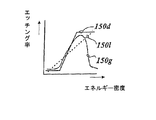
第1の層の透過特性について、特に紫外線の波長域では、第1および第2の領域中の凹凸構造部の異なる形状による達成可能な違いが、はっきりとわかることが実験により示されている。このように露光作用のために紫外線を用いた場合に、特に良い結果を達成できる。 Experiments have shown that the transmission characteristics of the first layer, especially in the ultraviolet wavelength range, clearly show the achievable differences due to the different shapes of the relief structures in the first and second regions. Thus, particularly good results can be achieved when ultraviolet rays are used for the exposure action.
露光作用によって活性化され洗浄工程において取り除かれる感光性の洗浄マスクの領域と、そこに配置された第1の層の領域とに関しては、感光性の洗浄マスクを感光層として使用できるが、感光層を露光作用の後に現像し、それから、第1の層のためのエッチングマスクを形成するような層を含めてもよい。 As for the photosensitive cleaning mask region activated by the exposure action and removed in the cleaning step and the first layer region disposed there, the photosensitive cleaning mask can be used as the photosensitive layer. A layer may be included that develops after the exposure action and then forms an etching mask for the first layer.
さらに、第1の凹凸構造部によって第1の層の透過率が高められ、それから、露光によって活性化される感光層が、第1の層のためのエッチング剤を形成する第1の領域に存在していてもよい。 Further, the transmittance of the first layer is increased by the first concavo-convex structure, and then the photosensitive layer activated by exposure exists in the first region forming the etching agent for the first layer. You may do it.
感光層は、陽画のフォトレジストから形成可能なフォトレジストであっても、あるいは、陰画のフォトレジストから形成可能なフォトレジストであってもよい。その方法では、同じ性質の状態にある複製層を使って、第1の層の異なる領域を取り除くことが可能である。 The photosensitive layer may be a photoresist that can be formed from a positive photoresist or a photoresist that can be formed from a negative photoresist. In that way, it is possible to remove different regions of the first layer using a replication layer in the same state of properties.
しかも、感光層は光機能高分子により形成され、第1の層のためのエッチング剤としては、例えば、アルカリまたは酸などが使用できる。 In addition, the photosensitive layer is formed of a photofunctional polymer, and as the etchant for the first layer, for example, alkali or acid can be used.
さらに、第1の層は、ほんの一部が取り除かれ、予め決まった透明性の程度に到達するとすぐにエッチング作用が阻止される。 Furthermore, the first layer is only partially removed and the etching action is stopped as soon as a predetermined degree of transparency is reached.
それによって、例えば、局所的に異なる透明性に基づいた偽造防止模様が製造可能となる。 Thereby, for example, a forgery prevention pattern based on locally different transparency can be manufactured.
例えば、アルミニウムが第1の層として使用される場合には、NaOHまたはKOHのようなアルカリは、均一に作用するエッチング剤として使用できる。また、PAN(リン酸化物,窒素酸化物および水の混合物)のような酸性媒質を用いることもできる。一般に、反応速度はアルカリの濃度と温度とに伴い上昇する。 For example, if aluminum is used as the first layer, an alkali such as NaOH or KOH can be used as a uniformly acting etchant. It is also possible to use an acidic medium such as PAN (a mixture of phosphorus oxide, nitrogen oxide and water). In general, the reaction rate increases with alkali concentration and temperature.
また、工程定数の選択は、過程の再現性と、多層体の耐性とに依存する。 The selection of the process constant depends on the process reproducibility and the multi-layer resistance.
アルカリを使ったエッチングを行う際に影響を与える要素としては、一般に、エッチング漕の構成、特に、エッチング剤の濃度,エッチング漕の温度,そして、エッチング漕でエッチングされる層に流入する流れの状態がある。 Influencing factors when performing etching using an alkali generally include the configuration of the etching trough, particularly the concentration of the etchant, the temperature of the etching trough, and the state of the flow flowing into the layer etched with the etching trough There is.
エッチング漕中のエッチング剤の濃度に関する一般的な変数の範囲は0.1%と10%との間の範囲にあり、温度に関する一般的な変数の範囲は20℃と80℃との間の範囲にある。 The general variable range for etchant concentration in the etch trough is in the range between 0.1% and 10%, and the general variable range for temperature is between 20 ° C and 80 ° C. It is in.
第1の層に対するエッチング作用は電気化学的に促進することができ、エッチング作用は、電気的な電圧の作用により強化される。 The etching action on the first layer can be promoted electrochemically, and the etching action is enhanced by the action of electrical voltage.
一般に、その作用は一様であるので、構造によって変わる表面積の増加に伴い、エッチングの効果は一層強くなる。 In general, since the action is uniform, the effect of etching becomes stronger as the surface area increases depending on the structure.
芳潤剤,緩衝物質,反応抑制剤,活性剤,触媒のような一般的な電気化学的な添加剤、および、例えば、酸化物層を取り除くための同様のもによって、エッチング過程を促進することができる。 Accelerate the etching process with common electrochemical additives such as humectants, buffer substances, reaction inhibitors, activators, catalysts, and the like, for example, to remove oxide layers. Can do.
それによって、エッチング過程の間に、エッチングの速度が遅くなる第1の層に関連する境界層の中では、エッチング過程に関わるエッチング媒体または強化剤が消耗する可能性がある。 Thereby, during the etching process, in the boundary layer associated with the first layer, which slows down the etching rate, the etching medium or reinforcing agent involved in the etching process may be consumed.
エッチング媒体を強制的に撹拌することによって、可能な限り適当な流れを生じさせるか、あるいは、超音波の刺激によりエッチング特性を改善する。 By forcibly stirring the etching medium, an appropriate flow is generated as much as possible, or etching characteristics are improved by ultrasonic stimulation.
さらに、エッチング過程は、エッチングの結果を最大限に引き出すために、時間的な温度プロファイルを有していてもよい。 Furthermore, the etching process may have a temporal temperature profile in order to maximize the etching results.
例えば、エッチングは、最初は低温状態から始めて、それから、作用周期を増すことによって、昇温された状態で作用させてもよい。細長いエッチング漕を通して多層体が引き出される場合には、異なる温度領域によるエッチング漕中の空間的な温度勾配によって、それは好適に実施される。 For example, the etching may start at a low temperature and then operate at an elevated temperature by increasing the working period. When the multilayer body is drawn through an elongated etching trough, it is preferably implemented by a spatial temperature gradient in the etching trough due to different temperature regions.
エッチング過程において、第1の層の最後の数ナノメートルの部分は、他の部分に比べてエッチングに対する堅牢性と耐性とを備えていることがわかる。したがって、最後の層の残りの部分を取り除くために、エッチング工程に対する僅かな機械的な補助が役に立つ。 In the etching process, it can be seen that the last few nanometers of the first layer are more robust and resistant to etching than the other parts. Thus, a slight mechanical aid to the etching process is helpful to remove the remaining part of the last layer.
上述の堅牢性は、おそらく第1の層が複製層上に形成されたときに境界層において生じた現象によって、第1の層についてのほんの僅かに異なる構成が原因となっている。 The robustness described above is due to a slightly different configuration for the first layer, possibly due to the phenomenon that occurred in the boundary layer when the first layer was formed on the replica layer.
この場合には、多層体をファインクロスで覆われたローラー上に通過させることによる拭き取り過程によって、第1の層の最後の数ナノメートルの部分をできるだけ取り除く。そして、そのクロスは多層体を傷つけることなく第1の層の残りの部分をぬぐい去る。 In this case, the last few nanometer parts of the first layer are removed as much as possible by a wiping process by passing the multilayer body over a roller covered with fine cloth. The cloth then wipes away the rest of the first layer without damaging the multilayer body.
したがって、エッチング工程には、液体で洗い流すような最終処理を含む必要はない。また、エッチング工程は、例えば、プラズマエッチングのような「ドライ工程」であってもよい。さらに、レーザー除去は、第1の層の剥離のためには有効であることが知られている。 Therefore, the etching process does not need to include a final process of washing away with a liquid. The etching process may be a “dry process” such as plasma etching, for example. Furthermore, laser removal is known to be effective for stripping the first layer.
大きな深さ対幅比を有する構造や、2つの隣接した立ち上がった部分の間の代表的な空き具合が入射光の波長より小さい構造、いわゆる0次構造、特に凹凸構造の場合には、たとえ反射層の反射率が高くて鏡面反射を起こす領域であっても、入射光の大部分を吸収することができる。 Even in the case of a structure having a large depth-to-width ratio or a structure in which a typical empty space between two adjacent raised portions is smaller than the wavelength of incident light, so-called zero-order structure, particularly a concavo-convex structure, even reflection Even in a region where the reflectance of the layer is high and causes specular reflection, most of the incident light can be absorbed.
レーザー放射が広がった領域で吸収される場合には、反射層中の第1の層は合焦したレーザービームによって照射され、同様に反射層は大きな深さ対幅比をもった上述の構造を有しており、強い吸収性を有する領域では温度が上昇する。 If the laser radiation is absorbed in the extended region, the first layer in the reflective layer is illuminated by a focused laser beam, and similarly the reflective layer has the above structure with a large depth to width ratio. The temperature rises in a region having strong absorbability.
反射層の除去または融解、あるいは、反射層の物質の凝固が起きている場合には、高レベルのエネルギー導入によって反射層を局所的に取り除くことができる。 When the reflective layer is removed or melted, or the material of the reflective layer is solidified, the reflective layer can be locally removed by introducing a high level of energy.
レーザーによるエネルギー導入は短い時間的周期でのみ有効であり、このように熱透過率の効果がほんの僅かしかない場合には、除去または凝固が凹凸構造部によって予め決められた領域でのみ生じる。 Energy introduction by a laser is effective only in a short time period. Thus, when the effect of heat transmittance is only slight, removal or solidification occurs only in a region predetermined by the concavo-convex structure.
レーザーによる除去に影響を与える要素には、構造化された感光性または洗浄性のラッカー層のように、それの上か下に、それを覆う追加層を有する可能性がある第1の層はもちろん、凹凸構造部の形状(空間的周期,深さ,向き,外形形状),光の波長,偏光,入射光放射の入射角,作用の継続時間(時間に依存する強度),レーザー放射の局所的照射線量,第1の層の特性と吸収特性などがある。 Factors that affect laser removal include the first layer, which may have an additional layer over or under it, such as a structured photosensitive or detergency lacquer layer. Of course, the shape of the concavo-convex structure (spatial period, depth, orientation, outer shape), light wavelength, polarization, incident angle of incident light radiation, duration of action (time-dependent intensity), locality of laser radiation Radiation dose, first layer characteristics and absorption characteristics.
とりわけ、Nd:YAGレーザーは、レーザー処理に適していることが知られている。それは、約1064mmの波長の光を放射し、好適には、パルスモードの変調により操作されている。 In particular, it is known that an Nd: YAG laser is suitable for laser processing. It emits light of a wavelength of approximately 1064 mm and is preferably operated by pulse mode modulation.
また、ダイオードレーザーを使用してもよい。レーザー放射の波長は、周波数の変化、例えば、共振によって変化させることができる。 A diode laser may also be used. The wavelength of the laser radiation can be changed by changing the frequency, for example by resonance.
レーザービームは、例えば、ガルバノメーターミラーと焦点レンズとを利用した、いわゆるスキャン装置などを使って多層体に入射される。 The laser beam is incident on the multilayer body using, for example, a so-called scanning device using a galvanometer mirror and a focus lens.
スキャン操作の間に、照射領域において、ナノ秒からマイクロ秒の範囲で継続するパルス光が放射され、そのパルス光が、その構造によって予め決まる上述の除去、あるいは、第1の層の凝固を行う。 During the scanning operation, pulsed light that continues in the nanosecond to microsecond range is emitted in the irradiated region, and the pulsed light performs the above-described removal or solidification of the first layer that is predetermined by the structure. .
パルスの継続時間は、一般にミリ秒を下回っており、好適には数マイクロ秒か、それより短い範囲にある。このように、ナノ秒からフェムト秒のパルス継続時間を使用することは実際に可能である。 The duration of the pulse is typically less than milliseconds and is preferably in the range of a few microseconds or less. Thus, it is actually possible to use nanosecond to femtosecond pulse durations.
第1の層へのレーザー放射の到達を部分的に阻止する過程で、構造化された形状の中に存在する感光層または洗浄マスクを自己参照する限りにおいては、レーザービームの正確な位置決めは必要ない。 Accurate positioning of the laser beam is necessary as long as it partially self-references the photosensitive layer or cleaning mask present in the structured shape in the process of partially blocking the laser radiation from reaching the first layer Absent.
その過程は、好適には、レーザービームが描く輪郭と、隣接したパルスの重なりとに関して適当な選択をすることによって、さらに最適化される。 The process is preferably further optimized by making appropriate choices regarding the contours drawn by the laser beam and the overlap of adjacent pulses.
しかしながら、複製層に配置されるか、あるいは感光層に開けられるか、または、凹凸構造部を有しかつマスクを洗い流すレジスト配置を利用して、多層体上でレーザーの経路を十分制御できるので、同一の凹凸構造部をもつか、感光層に開口部をもつかもたないかによって、マスクを洗い流す僅かな領域が照射される。 However, the laser path can be sufficiently controlled on the multilayer body by using a resist arrangement that is arranged in the replication layer, or opened in the photosensitive layer, or has a concavo-convex structure and wash away the mask. Depending on whether they have the same concavo-convex structure portion or whether the photosensitive layer has an opening, a small area where the mask is washed is irradiated.
例えば、カメラシステムは、そのような制御に使用できる。具体的には、点または線上にレーザーを合焦させる代わりに、短く放射するフラッシュ光のようにパルス制御した面発光装置を使用することもできる。 For example, a camera system can be used for such control. Specifically, instead of focusing the laser on a point or line, it is also possible to use a surface light-emitting device that is pulse-controlled like a flash light that is emitted shortly.
第1の層が、レーザー放射に関して透過的な1つ以上の追加層によって両側が覆われ、かつ、それが例えばエッチング媒体に直接アクセスできない場合であっても、凹凸構造部が有するレジスト配置を利用して、第1の層の部分的な除去が可能であるという事実が、とりわけレーザーによる除去工程の利点となっている。 Even if the first layer is covered on both sides by one or more additional layers that are transparent to the laser radiation and it is not directly accessible to the etching medium, for example, it uses the resist arrangement of the relief structure. Thus, the fact that the first layer can be partially removed is a particular advantage of the laser removal process.
ところで、第1の層はレーザーによって少しだけ破壊される。すなわち、第1の層の物質は、僅かに照射された領域で少しだけ透明性に影響を与える小さな集合体、または、見る人には光学的には見えないような小さいボールに幾度も破壊される。 By the way, the first layer is slightly destroyed by the laser. That is, the material of the first layer is destroyed many times in small aggregates that slightly affect the transparency in slightly irradiated areas, or small balls that are not optically visible to the viewer. The
第1の層が直接到達可能な場合には、レーザー処理後にまだ残っている複製層上の第1の層の残存物は、その次の洗浄処理によって選択的に除去できる。その第1の層のエッチングの後で、エッチングマスクの残留物が取り除かれる。 If the first layer is directly reachable, the residue of the first layer on the replication layer still remaining after the laser treatment can be selectively removed by a subsequent washing process. After etching the first layer, the etching mask residue is removed.
本発明の優れた構成によって、第2の層は、第1の層が取り除かれた領域の中に後から導入することができる。さらに、第1の層が取り除かれ、そして、第3の層によって置き換えられる。 Due to the superior configuration of the present invention, the second layer can be introduced later into the area from which the first layer has been removed. In addition, the first layer is removed and replaced by a third layer.
したがって、本発明に係る工程においては、層の部分的な除去が制限されることはない。 Therefore, in the process according to the present invention, partial removal of the layer is not limited.
しかしながら、本発明に係る工程では、層の境界を利用するのための追加工程の処理、または、追加領域を形成してもよい。 However, in the process according to the present invention, a process of an additional process for using the boundary between layers or an additional region may be formed.
また、差異を生じさせるために光学的密度の違いを利用する場合には、工程の処理を繰り返してもよい。 Further, when the difference in optical density is used to cause the difference, the process of the process may be repeated.
さらに、これらの工程が導電性の層または無電流の電気的刺激に適した層を含んでいる場合には、第1の層や第2の層や第3の層は、電気的刺激により強化するために使用できる。 Furthermore, if these processes include a conductive layer or a layer suitable for non-current electrical stimulation, the first layer, the second layer, and the third layer are reinforced by electrical stimulation. Can be used to
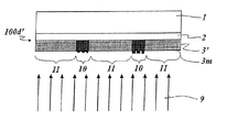
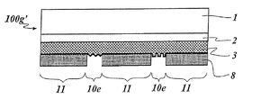
上述の工程にしたがって製造された多層体により、第2の領域は、第1の領域によって包囲された2つ以上の部分的な領域によって構成され、光学的に活性な第2の凹凸構造部が、第2の領域中の複製層に形成されている。 By the multilayer body manufactured according to the above-described process, the second region is constituted by two or more partial regions surrounded by the first region, and the optically active second uneven structure portion is formed. , Formed in the replication layer in the second region.
そして、第1の層は、第1の領域中で取り除かれかつ第2の凹凸構造部のもつ精密なレジスト配置を利用して配置された反射層である。 The first layer is a reflective layer that is removed using the precise resist arrangement of the second concavo-convex structure portion that is removed in the first region.
そのような多層体は、好都合なことに、偽造防止性を備えた偽造防止部材として使用できる。それらは、本発明と同様の工程によって形成されるので、特に線の細い線幅自体が、すでに偽造防止性を備えている。 Such a multilayer body can be advantageously used as an anti-counterfeit member having anti-counterfeit properties. Since they are formed by a process similar to that of the present invention, the thin line width itself is already provided with anti-counterfeiting properties.
さらに、それらの回折性を示す構造と、精密なレジスト配置における反射層に関係した、それらの配置とによって、それらの細線は、極端な困難さによってだけ模倣可能な光学的効果を生成することができる。 Furthermore, due to their diffractive structures and their arrangement in relation to the reflective layer in precise resist arrangements, these fine lines can produce optical effects that can only be mimicked by extreme difficulty. it can.
また、このような多層体には、例えば、転写フィルム,特にホットスタンピングフィルムまたはラミネートフィルムを含めることができる。 Such a multilayer body may include, for example, a transfer film, particularly a hot stamping film or a laminate film.
さらに、第1の領域は、第2の領域によって囲まれた2つ以上の部分的な領域によって構成されるか、または、それとは反対に構成され、また、第1の層は、第2の領域の中で取り除かれ、かつ、このように第1の凹凸構造部を有する精密なレジスト配置を利用して配置される反射層である。 Furthermore, the first region is constituted by two or more partial regions surrounded by the second region, or vice versa, and the first layer comprises the second region The reflective layer is removed using the precise resist arrangement that is removed in the region and thus has the first uneven structure portion.
本発明の優れた構成によって、第2の領域の部分的な領域または第1の領域の部分的な領域は、2mmより小さい、好適には1mmより小さい幅となるように提供される。 Due to the superior configuration of the present invention, the partial region of the second region or the partial region of the first region is provided with a width of less than 2 mm, preferably less than 1 mm.
さらに、本発明の優れた構成によって、本発明と同様の多層体の中で、第2の層が、第1の層が取り除かれた複製層の領域に配置される。 Furthermore, the excellent configuration of the present invention places the second layer in the region of the replication layer from which the first layer has been removed, in a multilayer body similar to the present invention.
例えば、第1の層や第2の層には、TiO2またはZnSのような絶縁体、または半導体が形成される。この場合には、第1の層と第2の層とが異なる屈折率を有しているので、光学的効果は、この異なる屈折率によって生じる。 For example, an insulator such as TiO 2 or ZnS or a semiconductor is formed in the first layer or the second layer. In this case, since the first layer and the second layer have different refractive indexes, the optical effect is caused by the different refractive indexes.
第1の層や第2の層には、例えば、一方の層を導電体として形成でき、他方の層を電気的絶縁体として形成できるように、両方の層が透明な層として形成可能な点で高分子を使用してもよい。例として、第1の層や第2の層は、電気素子,例えば、アンテナ,コンデンサー,コイルまたは有機半導体素子を形成することができる。 In the first layer and the second layer, for example, both layers can be formed as transparent layers so that one layer can be formed as a conductor and the other layer can be formed as an electrical insulator. High polymers may be used. As an example, the first layer or the second layer can form an electrical element, such as an antenna, a capacitor, a coil, or an organic semiconductor element.
上述したように、本発明と同様の工程によって、精密なレジスト配置に配列可能な追加層を多層体上に備えることができる。 As described above, an additional layer that can be arranged in a precise resist arrangement can be provided on the multilayer body by a process similar to that of the present invention.
層の部分的な除去あるいは部分的な腐食部の連続体、および、第1および第2の領域中の構造を有する連合体が、異なる回折性を示す構造が互いに組み合わされている領域中で形成されるように選択されている。 A continuum of partial removal or partial erosion of the layer and an association having structures in the first and second regions are formed in the region where structures exhibiting different diffractive properties are combined with each other Have been selected to be.
これには、例えば、異なる深さ対幅比を有しかつバックグラウンドの正面に配置された第1のキネグラムおよび第2のキネグラムが使用される。 For example, a first kinegram and a second kinegram having different depth to width ratios and arranged in front of the background are used.
その例において、蒸着された銅層は、第1のキネグラムの偽造防止模様の領域の中にだけ残されている。そして、アルミニウムは、全表面上で蒸着によって付与され、適当な工程を実行することによって、バックグラウンド領域で取り除かれる。 In that example, the deposited copper layer is left only in the anti-counterfeited areas of the first kinegram. Aluminum is then applied by vapor deposition over the entire surface and is removed in the background area by performing appropriate processes.
これにより、レジスト配置を利用して、部分的に金属被覆の処理がなされ、かつ、見る人に面した金属層とは異なった2つのデザインが生成される。 This creates two designs that are partially metallized using resist placement and that are different from the metal layer facing the viewer.
複製層に形成された凹凸構造部は、液晶高分子の配置のために作用するように選択できる。この場合において、複製層や第1の層は、液晶による配向層として使用することができる。 The concavo-convex structure portion formed in the replication layer can be selected so as to act for the arrangement of the liquid crystal polymer. In this case, the replication layer and the first layer can be used as an alignment layer made of liquid crystal.
例えば、溝形状の中の構造は、その位置で、架橋、あるいは、いくつかの他の方法により、それらの方向に、それらが固定されるより前に、そのような構造に関連して液晶が配向するような配向層の中に取り入れられる。 For example, the structure in the groove shape may have a liquid crystal associated with such a structure before it is fixed in that direction by cross-linking or some other method at that location. Incorporated into the alignment layer to align.
架橋された液晶層は第2の層を形成し、その配向層は、その構造の方向が一様に変わる領域を有してもよい。 The cross-linked liquid crystal layer forms a second layer, and the alignment layer may have a region whose structure direction changes uniformly.
そのような回折性を示す構造によって形成された領域が、例えば、回転偏光をもった偏光体を通して見られる場合には、はっきりと認識できる様々な偽造防止模様、例えば、動きによる効果は、このように領域の偏向方向を線形的に変化させることにより生成可能である。 If the region formed by such a diffractive structure is viewed through, for example, a polarizer with rotational polarization, various anti-counterfeiting patterns that are clearly recognizable, It can be generated by linearly changing the deflection direction of the region.
配向層は、局所的に異なる配置がなされた液晶の配向によって回折性を示す構造を有しているので、偏光で見ることを考慮したときに、液晶によって、例えば、ロゴのような情報アイテムを表現することもできる。 The alignment layer has a structure that exhibits diffractive properties due to the alignment of the liquid crystals that are locally arranged differently. It can also be expressed.
ところで、第1の層や第2の層は有色層として形成する。また、有色領域は後述する工程によっても製造できる。 By the way, the first layer and the second layer are formed as colored layers. In addition, the colored region can be manufactured by a process described later.
多層体は、本発明による工程によって、有色の感光層または洗浄マスクを使って製造される。この場合には、顔料または可溶性の染料によって着色可能である。その後で、感光層は、第1の層を通して、例えば、紫外線によって露光される。 The multilayer body is manufactured using a colored photosensitive layer or cleaning mask by the process according to the invention. In this case, it can be colored with pigments or soluble dyes. Thereafter, the photosensitive layer is exposed through, for example, ultraviolet light through the first layer.
そして、陽画のレジストか、または、陰画のレジストかどうかによって、第1の領域の中で固化するか、または破壊される。この場合には、陽画および陰画のレジスト層は、相互に配置されたレジスト配置によって付与でき、同時に露光もできる。 Depending on whether the resist is a positive resist or a negative resist, it is solidified or destroyed in the first region. In this case, the positive and negative resist layers can be applied by the mutual arrangement of the resists and can be exposed simultaneously.
また、この場合には、第1の層はマスクとして機能しており、そして、第1の層は、好適にはフォトレジストに直接接触するように配置されるので、精密な露光が効果的に行われる。 Also, in this case, the first layer functions as a mask, and the first layer is preferably arranged so as to be in direct contact with the photoresist, so that precise exposure is effective. Done.
最終的にはフォトレジストを現像したときに、硬化されていない領域が洗浄されるか、あるいは破壊された領域が取り除かれる。 Eventually, when the photoresist is developed, the uncured areas are cleaned or the destroyed areas are removed.
ところで、現像された有色のフォトレジストを使用した第1の層が、透明か、または紫外線に関して不透明になっている領域にも、それぞれのフォトレジストへの依存性が精密に存在する。 By the way, the dependence on each photoresist exists precisely also in the area | region where the 1st layer using the developed colored photoresist is transparent or is opaque with respect to an ultraviolet-ray.
第1の層と同様に構成されたフォトレジスト層の、残された耐性を増大させるために、残された領域は、好適には現像作業後に硬化するとよい。 In order to increase the remaining resistance of the photoresist layer configured similarly to the first layer, the remaining area is preferably cured after the development operation.
最終的にマスクとして使用される第1の層は、多層体が、見ている人に対してだけ高解像度のフォトレジストの「カラープリント」を有するが、他からは透明であるような拡張へのさらなるエッチング処理によって取り除くことができる。そのような状況において、フォトレジストはエッチングマスクとして機能する。 The first layer that will eventually be used as a mask is an extension where the multilayer body has a “color print” of high-resolution photoresist only for the viewer, but is transparent from the others. Can be removed by further etching. In such a situation, the photoresist functions as an etching mask.
好都合なことに、高解像度の画素を、この方法で形成できる。本発明の範囲から離れることなく、精密なレジスト配置を利用して、異なった色の画素を付与することができ、それらを、例えば、点状のラスターイメージに配置できる。 Conveniently, high resolution pixels can be formed in this way. Without leaving the scope of the present invention, precise resist placement can be used to provide pixels of different colors, which can be placed, for example, in a dot-like raster image.
第1の層に関しては、一つの工程によって、異なる多層体が最初のレイアウトで製造できるので、それによって、例えば、異なる露光とエッチング工程とが一緒に組み合わされるか、または、連続体の中で運び出される。 With respect to the first layer, different multilayer bodies can be produced with an initial layout in one step, so that, for example, different exposure and etching steps are combined together or carried out in a continuum. It is.
そして、本発明による工程を用いたときには、精密なレジスト配置を利用して連続的に付与された層と、その位置決めとが、工程数が増加したとしても可能となる。 And when the process according to the present invention is used, the layer continuously applied using the precise resist arrangement and the positioning thereof can be performed even if the number of processes is increased.
第1の層や第2の層が複数の部分層によって形成される場合には、特に、前記部分層が薄膜系を形成する場合には、さらなる光学的効果を生成できる。 When the first layer or the second layer is formed of a plurality of partial layers, particularly when the partial layer forms a thin film system, further optical effects can be generated.
そして、このような部分層は異なる物質によって形成される。そのような形状では、上述の薄膜系は、少しも利用できない。 Such a partial layer is formed of different materials. With such a shape, the thin film system described above cannot be used at all.
その方法によって、例えば、ナノテクノロジーによる機能素子も製造できる。例えば、μmオーダーの広がりを伴うバイメタルスイッチを2つの異なる金属層によって製造することができる。 By the method, for example, a functional element by nanotechnology can also be manufactured. For example, a bimetal switch with a spread on the order of μm can be manufactured with two different metal layers.
さらに、本発明に係る構成によって、第1の層や第2の層が光学的パターンを形成する。この光学的パターンには、ラスターイメージを含めることもできる。 Furthermore, according to the configuration of the present invention, the first layer and the second layer form an optical pattern. The optical pattern can also include a raster image.
第1の層のラスタリングの効果としては、反射層が下に敷かれかつ可能な限り異なる回折性を示す回折構造を有するラスターの要素の他に、反射層なしで透明な領域を表すラスターの要素が備えられる効果も可能である。 The effect of rastering of the first layer is that of the raster representing the transparent area without the reflective layer, in addition to the elements of the raster having a diffractive structure underlying the reflective layer and exhibiting as different diffractive properties as possible. The effect that the element is provided is also possible.
この点に関して、マスターの効果として、振幅変調によるマスタリングか、または、領域変調によるマスタリングかを選択できる。 In this regard, the master effect can be selected from mastering by amplitude modulation or mastering by region modulation.
注目すべき光学的効果は、このような反射性または回折性の領域および非反射性,周囲が回折性も有し透明性を有する領域の組み合わせによって達成できる。 Remarkable optical effects can be achieved by a combination of such reflective or diffractive regions and non-reflective, surrounding regions that are also diffractive and transparent.
そのようなラスタリングイメージが、例えば、数字を含む文章の中の窓おいて、窓の中に配列される場合には、透過光モードにおいて、透明なラスターイメージが認識できる。 When such a rastering image is arranged in a window in a sentence containing numbers, for example, a transparent raster image can be recognized in the transmitted light mode.
入射光のモードでは、反射面によって回折する光または反射する光がないような与えられた角度範囲においてだけ、ラスターイメージを目で見ることができる。 In the incident light mode, the raster image can be seen with the eye only in a given angular range where there is no light diffracted or reflected by the reflecting surface.
さらに、そのような要素は透明な窓において使用可能なだけでなく、有色の印影にも適用できる。 Furthermore, such elements can be used not only in transparent windows but also in colored impressions.
別の角度範囲では反射光によって見ることができないとしても、与えられた角度範囲においては、回折構造または他の構造によって、例えば、ラスターイメージの中で有色の印影を目で見ることができる。 Even if it cannot be seen by reflected light in another angular range, for a given angular range, for example, colored impressions can be seen in a raster image by a diffractive structure or other structure.
さらに、適切に選択されたマスターの効果によって、それらの反射性を減少させる複数の外向き反射領域を生成できる。 In addition, the effects of appropriately selected masters can generate a plurality of outwardly reflective areas that reduce their reflectivity.
また、第1の層は完全には取り除かれないが、その層厚を単に減少させるためにも使用できる。 Also, although the first layer is not completely removed, it can also be used to simply reduce its layer thickness.
例えば、光学的な特性や電気的な特性を変えるか、あるいは、装飾的な効果を生じさせるために、相互に重なり合った層を有する領域を形成可能な場合には、そのような構成は、特に有益である。 For example, such a configuration is particularly useful when it is possible to form regions with layers that overlap one another in order to change the optical or electrical properties or to produce a decorative effect. It is beneficial.
複製層を使った露光マスクと、第2の層を形成するための第1の層とを使用する上述した工程において複製層が露光マスクの搬送層に付与される。 In the above-described process using the exposure mask using the replication layer and the first layer for forming the second layer, the replication layer is applied to the transport layer of the exposure mask.
その工程は、好適には、上述のさらなる処理と組み合わせることもできる。すなわち、請求項46の工程は、請求項1の工程と同一の方法で、さらに、請求項2ないし請求項25の特徴と組み合わせることができる。
The process can also be combined with further processing as described above. That is, the process of claim 46 can be combined with the features of
また、それは、請求項51で述べられているような上述の工程で使用されている露光マスクにも適用される。 It also applies to the exposure mask used in the above process as described in claim 51.
さらに、感光層または感光性の洗浄マスクは、第2の層上に配列され、第2の層を通して露光される。 In addition, a photosensitive layer or photosensitive cleaning mask is arranged on the second layer and exposed through the second layer.
上述した目的のためには、第2の層は透明な層として形成されていてはならない。第2の層は、感光層または感光性の洗浄マスクの全領域で、光の強度を同程度に減少させるような不透明層として形成できる。 For the purposes described above, the second layer must not be formed as a transparent layer. The second layer can be formed as an opaque layer that reduces the light intensity to the same extent over the entire area of the photosensitive layer or photosensitive cleaning mask.
したがって、露光マスクの中での光学的密度に関する違いは維持され、露光マスクの実際の見た目が、感光層または感光性の洗浄マスク上に生成される。 Thus, the difference in optical density within the exposure mask is maintained and the actual appearance of the exposure mask is produced on the photosensitive layer or photosensitive cleaning mask.
洗浄マスクを使用したときに、露光マスクと洗浄マスクとの間のビーム経路に、第2の層が配置されないような最後の最低層として第2の層は使用できる。このような場合には、第2の層は完全に不透明であってもよい。 When a cleaning mask is used, the second layer can be used as the last lowest layer so that the second layer is not placed in the beam path between the exposure mask and the cleaning mask. In such cases, the second layer may be completely opaque.
そして、洗浄マスクの露光された領域を洗い流すことによって、それらの領域に配置された第2の層が取り除かれる。 Then, by washing away the exposed areas of the cleaning mask, the second layer disposed in those areas is removed.
好都合なことに、第2の層の取り除かれなかった領域の下に残った洗浄マスクは、保護層の付与による周囲の環境的な影響により閉じこめられる。そして、この方法によって、特に確実な多層体が形成される。 Conveniently, the cleaning mask remaining under the unremoved area of the second layer is confined by the surrounding environmental influence due to the application of the protective layer. A particularly reliable multilayer body is formed by this method.
さらに、本発明の優れた構成において、露光マスクは多層体に結合する。 Further, in the superior configuration of the present invention, the exposure mask is bonded to the multilayer body.
上述したように、本発明による工程によって、多層体を形成する多くの異なる可能な方法が使用される。そして、その工程の処理は、1回だけ使用するとは限らない。 As mentioned above, the process according to the invention uses a number of different possible ways of forming a multilayer body. And the process of the process is not necessarily used only once.
したがって、最初から露光マスクとして形成された多層体が生成された場合には、そのとき、例えば、半導体製品の露光マスクのような従来の露光マスクとして使用することができる。 Therefore, when a multilayer body formed as an exposure mask from the beginning is generated, it can be used as a conventional exposure mask such as an exposure mask for semiconductor products.
そのような露光マスクは、第2の多層体に、いつまでも結合していることはなく、露光作業の後に取り除くことができる。 Such an exposure mask is not permanently bonded to the second multilayer body and can be removed after the exposure operation.
しかしながら、露光マスク上の層による方法によって形成するように、第2の多層体は利用されている。 However, the second multilayer body is utilized so as to be formed by a method using a layer on the exposure mask.
露光マスクが、露光か、または、その後に取り除かれるように用意されている場合には、そのような除去を許すような露光マスクと第2の多層体との間に、分離層を配置することができる。 If the exposure mask is prepared to be exposed or subsequently removed, a separating layer is placed between the exposure mask and the second multilayer body allowing such removal. Can do.
さらに、本発明の優れた構成によって、露光マスクは、第2の多層体に、いつまでも結合し、この方法によって、最終製品のようなものとして、あるいは、さらにずっと複雑な多層体の追加層の構造物を生成する中間媒体のようなものとして利用される第3の多層体が形成される。 Furthermore, due to the superior configuration of the present invention, the exposure mask is indefinitely bonded to the second multilayer body, and by this method, as a final product, or a much more complex multilayer body additional layer structure. A third multilayer body is formed which is used as an intermediate medium for producing the product.
上述したように、多層体は、可撓性のフィルム体や、例えば半導体チップや、例えば、携帯電話のような電子装置の表面などの剛性体などのどちらであってもよい。 As described above, the multilayer body may be either a flexible film body, a rigid body such as a semiconductor chip or the surface of an electronic device such as a mobile phone, for example.
図1は、搬送フィルム1上に、機能層2,複製層3,金属層3mおよび接着層12が配置された多層体100を示している。
FIG. 1 shows a
機能層2は、その層が複数の部分層から形成されて備えられる点において、主に多層体の力学的かつ化学的な安定性を高める作用をする層であり、さらに公知の方法によって光学的効果を生じるように設計されている。
The
機能層2は、ワックスからなる層や除去される層として形成された層を含んでいてもよいし、機能層2を省いて複製層3を直接搬送フィルム1上に配置してもよい。
The
さらに、搬送フィルム1それ自体を複製層として形成してもよい。
Furthermore, you may form the
また、多層体100は、接着層12により基層に接着されるような、例えば、ホットスタンピングフィルムなどの転写フィルムの一部分であってもよい。
Further, the
接着層12は、熱の効果によって溶融して、多層体を基層の表面に取り外せないように接着する接着剤であってもよい。
The
搬送フィルム1は、力学的にも熱的にも安定なPETからなるフィルムによって形成することができる。
The
複製層3の中に異なる構造を備えた領域を公知の工程によって形成することができる。
Regions with different structures in the
本実施例では、これらの領域は、回折性の構造を有する領域4と反射領域6とを含んでいる。
In this embodiment, these regions include a
複製層3上に配置された金属層3mは、回折性を示す構造4に対応した配置に配置された腐食領域10dを有している。多層体100では、領域10dの部分が、透明あるいは部分的に透明に見える。
The
ところで、図2〜図8は、多層体100の製造工程を示しており、図1と同一部分は同一の符号によって記載されている。
2 to 8 show a manufacturing process of the
図2は、搬送フィルム1上に機能層2と複製層3とが配置された多層体100aを示している。
FIG. 2 shows a
複製層3は、例えば、ホットスタンピングのような公知の工程によって多層体100aの表面に形成されている。
The
この目的のために、具体的には複製層3を形成するために、熱可塑性物質の複製ラッカー層が、焼き付け、吹きつけ、または、ラッカリングによって付与され、そして、凹凸の構造部が加熱ダイまたは加熱転写ローラーによって複製ラッカー層に形成される。
For this purpose, in particular to form the
なお、複製層3は、例えば、転写ローラーによって構造化された紫外線硬化性の転写ラッカー層であってもよい。
The
どのような構造化であっても、露光マスクを通過した紫外線によって生成することができ、この方法により、領域4と領域6とが複製層3に形成できる。
Whatever the structure, it can be generated by the ultraviolet rays that have passed through the exposure mask, and the
領域4は、例えば、ホログラムによる光学的活性領域やキネグラムの偽造防止模様であってもよい。
The
ところで、図3は、金属層3mが例えばスパッタリングにより一様な面密度で複製層3に付与される工程によって、図2の多層体100aから形成された多層体100bを示している。
Incidentally, FIG. 3 shows a
本実施例において、金属層3mは、約10nmの層厚を有している。
In this embodiment, the
領域4および領域6が、低いレベルの透過率、例えば10%と0.001%との間の透過率となるように、すなわち、光学的密度が1と5との間(できれば1.5と3との間)となるように、金属層3mの層厚が好適に選択されている。
したがって、領域4および領域6において、金属層3mの光学的密度、すなわち、透過率の負の常用対数は1と3との間にある。金属層3mは、好適には、1.5と2.5との間の光学的密度を含むものとする。
Therefore, in the
したがって、領域4および領域6は不透明に見えるか、あるいは、それらを見ている人の目に光を反射するかのように見える。
Thus,
層3mが2より大きい光学的密度を有しかつ平坦な表面に付与されるときに、層3mが実質的に不透明となる層厚でもって付与されることは、ここでは特に有益である。
It is particularly beneficial here that the
金属層3mの透過特性上、金属層3mが複製層3に厚く付与されるほど、領域4の回折性を示す構造によって生成される有効な光学層の厚さの変化による効果が大きくなる。
In view of the transmission characteristics of the
回折性を示す構造に起因する金属層3mの有効な光学的な厚さの変化は、蒸着された層厚に近似的に比例し、それゆえ光学的密度に近似的に比例することが研究によって示されている。
Research has shown that the effective optical thickness change of the
光学的密度が透過率についての負の対数を示すので、領域4と領域6との間の透過率の変化は、金属物質について表面に付与する量を増大させるにしたがい、比例する以上に増大する。
Since the optical density indicates a negative logarithm for transmittance, the change in transmittance between
しかしながら、領域6に比べて、領域4では金属層3mの厚さが減少するので、金属層3mの光学的密度は領域4と領域6とでは異なっていることに注意すべきである。
However, it should be noted that the optical density of the
金属層3mの光学的密度の応答性は、構成部分の0ではない深さ対幅比と、深さ対幅比の増大によって減少する金属層の厚さとによる領域4の表面積の増加に依存する。
The optical density responsiveness of the
周期的構造を有する表面領域を好適に増加させることにより、ディメンションのない深さ対幅比と空間的周期とによって模様が特徴づけられる。 By suitably increasing the surface area with a periodic structure, the pattern is characterized by a dimensionless depth-to-width ratio and a spatial period.
このような構造によって、周期的な連続体中の「山」と「谷」が形成されている。なお、ここでは「山」と「谷」との間の空間を深さと称すると共に、2つの「山」の間の空間を幅と称している。 With such a structure, “mountains” and “valleys” in the periodic continuum are formed. Here, the space between “mountain” and “valley” is referred to as depth, and the space between two “mountains” is referred to as width.
上述の深さ対幅比が大きくなるほど、それに応じて「山の側面」が急勾配になり、それに応じて「山の側面」上に堆積する金属層3mが薄くなる。
As the depth-to-width ratio increases, the “mountain side” becomes steeper accordingly, and the
その状況が、「谷」の深さより数倍大きい間隔で互いに相対的に配列でき、断続的に配置された「谷」を含む場合にも、その効果が観測される。 The effect is also observed when the situation includes intermittently arranged “valleys” that can be arranged relative to each other at intervals several times larger than the depth of the “valley”.
このような場合において、「谷」の幾何学を正確に記述するために、深さ対幅比によって整理することにより、「谷」の深さを「谷」の幅と関係づけるべきである。 In such a case, to accurately describe the geometry of the “valley”, the depth of the “valley” should be related to the width of the “valley” by organizing with a depth to width ratio.
減少させた光学的密度を有する領域を生成するときに、それらの依存性に関する個別の変数を知ること、および、適切に選択することは重要である。 When generating regions with reduced optical density, it is important to know the individual variables regarding their dependence and to choose appropriately.
光学的密度の減少の程度は基層や照明などに依存して変化していてもよい。この点において、金属層における光の吸収が重要な役割を果たす。一例として、クロムおよび銅は、ある条件下で、ほとんど光を反射しない。 The degree of decrease in optical density may vary depending on the base layer, illumination, and the like. In this respect, light absorption in the metal layer plays an important role. As an example, chromium and copper reflect little light under certain conditions.
表1は、波長λ=550nmの光の波長において、樹脂フィルム(屈折率n=1.5)の間に配置されたAg,Al,Au,Cr,Cu,RhおよびTiの金属層の確認された反射率を示している。 Table 1 confirms the Ag, Al, Au, Cr, Cu, Rh, and Ti metal layers disposed between the resin films (refractive index n = 1.5) at the wavelength of light of wavelength λ = 550 nm. Reflectivity.
この場合には、厚さの比εは、反射率Rが最大値Rmaxの20%となるような金属層厚tと、反射率Rが最大値Rmaxの80%となるような金属層厚tとの商として定義される。 In this case, the thickness ratio ε is such that the metal layer thickness t is such that the reflectance R is 20% of the maximum value Rmax, and the metal layer thickness t is such that the reflectance R is 80% of the maximum value Rmax. Defined as the quotient of

発見的な考察の視点から、銀および金(AgおよびAu)は、大きな最大反射率Rmaxを有しており、透明性を生成する上述の例において、金属層の光学的密度を減少させるような比較的小さい深さ対幅比を要求する。 From a heuristic point of view, silver and gold (Ag and Au) have a large maximum reflectivity Rmax, and in the above example producing transparency, such as reducing the optical density of the metal layer. Requires a relatively small depth-to-width ratio.
一般に、アルミニウム(Al)も大きな最大反射率Rmaxを有するが,アルミニウム(Al)では、一層大きな深さ対幅比が要求される。 In general, aluminum (Al) also has a large maximum reflectance Rmax, but aluminum (Al) requires a greater depth-to-width ratio.
したがって、金属層は、好適には銀または金によって形成するとよいが、他の金属または合金によって形成してもよい。 Therefore, the metal layer is preferably formed of silver or gold, but may be formed of other metals or alloys.
ところで、表2は、350nmの格子間隔を有する線形格子、正弦格子として形成されかつ異なる深さ対幅比を有する凹凸構造部のための厳密な回折計算から得られた計算結果を示している。 By the way, Table 2 shows calculation results obtained from strict diffraction calculation for a concavo-convex structure portion formed as a linear grating having a grating interval of 350 nm, a sine grating, and having different depth-to-width ratios.
そして、凹凸構造部は、呼び厚さがt0=40nmの銀によってコーティングされている。また、凹凸構造部を照射する光は、波長λ=550nm(緑色)であり、TE偏光か、またはTM偏光である。 The concavo-convex structure is coated with silver having a nominal thickness of t 0 = 40 nm. The light irradiating the concavo-convex structure portion has a wavelength λ = 550 nm (green) and is TE-polarized light or TM-polarized light.
表2からわかるように、深さ対幅比とは別に、特に透明性または透過性の程度は、放射光の偏光に依存している。その偏光に対する依存性は、深さ対幅比d/h=1.1について表2に示されている。追加層の選択的な配置を利用することによって、その効果を発揮させることができる。 As can be seen from Table 2, apart from the depth to width ratio, the degree of transparency or transparency in particular depends on the polarization of the emitted light. Its dependence on polarization is shown in Table 2 for a depth to width ratio d / h = 1.1. The effect can be exhibited by utilizing the selective arrangement of the additional layer.
さらに、金属層3mの透明性や反射率は波長に依存することがわかる。その波長の効果は、特にTE偏光の光に対しては、はっきりとわかる。
Furthermore, it turns out that the transparency and reflectance of the
さらに、光の入射角が通常の入射角と異なっている場合には、透明性や透過率は減少する、すなわち、光が直角に入射しない場合には、透明性は減少することがわかる。 Further, it can be seen that when the incident angle of light is different from the normal incident angle, the transparency and transmittance are reduced, that is, when the light is not incident at a right angle, the transparency is decreased.
制限された入射光の光の円錐中では、反射領域6に比べて、金属層3mが透明であるか、あるいは、ほとんど不透明ではないということは重要である。したがって、追加層の選択的な配置を利用した効果によって、斜めに照射されたときに、金属層3mが不透明となるようすることができる。
In the limited cone of incident light, it is important that the
また、光学的密度の変化は、構造の深さ対幅比の他に、構造の空間的周期性によっても影響を受ける。 The change in optical density is also affected by the spatial periodicity of the structure in addition to the depth to width ratio of the structure.
さらに、例えば、構造の第1の領域の中での空間的周期と凹凸構造の深さとの積とが、構造の第2の領域の中での空間的周期と凹凸構造の深さとの積より大きい場合には、その構造に付与される層の透明性の特徴に変化が生じることが知られている。 Further, for example, the product of the spatial period in the first region of the structure and the depth of the concavo-convex structure is greater than the product of the spatial period in the second region of the structure and the depth of the concavo-convex structure. When large, it is known that changes occur in the transparency characteristics of the layer imparted to the structure.
しかしながら、透明性や透過率が異なっている領域の製造は、他の作用、例えば、異なる配置構造の結果としての透過量の偏光依存性によっても、構造の形状因子、すなわち、矩形,正弦,鋸歯状または同一の空間的周期と凹凸構造の深さとの積を有しかつ異なる透過量に影響を与え得る他の輪郭の構造によっても、そして、空間的な構造や構造の組み合わせや構造配置の組み合わせにより配置された第1の層の蒸着によっても、達成可能である。 However, the manufacture of regions with different transparency and transmittance can be caused by other effects, such as the polarization dependence of the amount of transmission as a result of different arrangements, such as the shape factor of the structure, i.e. rectangular, sine, sawtooth. By other contoured structures that have a product of the shape or the same spatial period and the depth of the concavo-convex structure and can affect different transmission amounts, and combinations of spatial structures, structures, and structural arrangements It can also be achieved by vapor deposition of the first layer arranged by.
第1の構造が、統計的な分析結果に影響を与えるような構造である場合には、例えば、つや消し構造,相関長,凹凸の深さ,および、分析結果の統計的分布などが、透過率に影響を与える典型的な変数となり得る。 In the case where the first structure is a structure that affects the statistical analysis result, for example, the matte structure, the correlation length, the depth of the unevenness, and the statistical distribution of the analysis result have the transmittance. It can be a typical variable that affects
また、例えば、透明度や透過率の違いに影響を与える領域を形成するために、第1の領域および第2の領域の中で、1つ以上の上記変数が異なっている凹凸構造部を使用することもできる。 In addition, for example, in order to form a region that affects the difference in transparency and transmittance, one or more concavo-convex structure portions in which one or more of the above variables are different are used in the first region and the second region. You can also.
図4は、図3に示される多層体100bによって形成された多層体100cと、感光層8とを示している。この感光層8は、液体中で凹刻するような、従来のコーティング工程によって形成された有機層であってもよい。
FIG. 4 shows the
感光層8は、蒸着によって付与するか、あるいは、ドライフィルムの形態でラミネーションによって貼着することによって付与することができる。
The
感光層8は、例えば、0.1g/m2から50g/m2の面密度で、金属層3mに付与されたClariant社製のAZ1512,AZ P4620、あるいは、Shipley社製のS1822のような陽画のフォトレジストであってもよい。
The
層厚は所望の解像度や過程に依存する。例えば、引き上げ過程は、約1g/m2の面密度に対して、一層あたり1μmより厚い層からなる、かなり厚い層に影響を及ぼす。この好適な表面積に対する重量は、0.2g/m2と10g/m2との間の範囲にある。 The layer thickness depends on the desired resolution and process. For example, the pulling process affects a much thicker layer consisting of layers thicker than 1 μm per layer for an areal density of about 1 g / m 2 . The weight for this preferred surface area is in the range between 0.2 g / m 2 and 10 g / m 2 .
層の付与によって全面が覆われてもよいが、部分的な領域、例えば、上述の領域4と領域6との外側に配置された領域に付与することもできる。
Although the entire surface may be covered by the application of the layer, it may be applied to a partial region, for example, a region disposed outside the
例えば、ランダムなパターン、あるいは、繰り返される絵柄や文字によって形成されるパターンのようなデザイン、あるいは、例えば、装飾的な画像表現などを備えたレジスト配置を利用して、これにより相対的に少し粗く配列しなければならない領域を含めることができる。 For example, using a resist pattern with a random pattern, or a design such as a pattern formed by repeated pictures or characters, or a decorative image representation, for example, which makes it relatively rough Regions that must be arranged can be included.
ところで、図5は、搬送フィルム1を通して、図4における多層体100cを露光することによって形成される多層体100dを示しており、露光作業のための紫外線光9が示されている。
5 shows a
ところで、上述したように、0より大きい深さ対幅比を有する回折性の構造を備えた領域4は、反射領域6より低い光学的密度を有しているので、紫外線照射の作業によって、ほとんど露光されていない領域11とは、それらの化学的な特性に関して異なり、一層強く露光された領域10が感光層8の中に生成される。
By the way, as described above, the
図5に示す実施例は、多層体100dの全領域で等しい強度をもった均一な光を含んでいる。
The embodiment shown in FIG. 5 includes uniform light having the same intensity in the entire region of the
しかしながら、部分的な光を、
a) 例えば、デザインの要素として大きな深さ対幅比をもった構造を残し、それらを腐食(エッチング)しないように、
b) 例えば、露光作業の間に多層体100dと共に移動する帯状のマスクを通すことによって、付加的な情報を取り入れるように、
c) 例えば、シリアルナンバーのような個別の情報を取り入れするように、使用することもできる。
However, partial light
a) For example, leave a structure with a large depth-to-width ratio as an element of the design and do not corrode (etch) them.
b) To incorporate additional information, for example by passing a strip-shaped mask that moves with the
c) It can also be used to incorporate individual information such as, for example, a serial number.
プログラム可能な偏向装置(空間的光変調器)や、制御されたレーザーによって短時間で露光する方法により認証性が導入される。 Authenticity is introduced by a programmable deflection device (spatial light modulator) or a method of exposing in a short time with a controlled laser.
したがって、この方法ではアルファベットと数字との組み合わせによる認証性が与えられたところにだけが適切な深さ対幅比になっており、エッチング処理領域が形成されている。 Therefore, in this method, an appropriate depth-to-width ratio is obtained only where authentication is provided by a combination of alphabets and numerals, and an etching process region is formed.
また、光の入射角だけでなく光の波長と偏光も構造を明確に強調して、選択的な生成を可能にする光の変数である。 Further, not only the incident angle of light but also the wavelength and polarization of light are light variables that clearly emphasize the structure and enable selective generation.
また、この目的のためには、化学的な特性も使用できる。例えば、領域10と領域11とでは、溶媒に対する、それらの可溶性が異なっていてもよい。
Chemical properties can also be used for this purpose. For example, the solubility in the solvent may be different between the
さらに、図6に示されるように、紫外光による露光処理の後で、この方法によって感光層8を「現像」してもよい。
Further, as shown in FIG. 6, the
異なる光学的密度の領域で形成された露光によって生成された感光層中の潜像により、可視的なイメージが金属層3mのマスクとして感光層の「現像」による領域の除去により生成される。
Due to the latent image in the photosensitive layer produced by exposure formed in areas of different optical density, a visible image is produced by removal of the areas by “development” of the photosensitive layer as a mask for the
驚くべきことではあるが、人の目には見える程度の透明性を得るために、領域4中で常に深さ対幅比を0.3より大きくすると、感光層の現像には十分な深さ対幅比であっても、実質的には足りない可能性があることがわかってきた。
Surprisingly, in order to obtain transparency that is visible to the human eye, a depth to width ratio of greater than 0.3 in
また、見た目を考慮した際に、領域4が透明性を示す程に、金属層3mを薄くする必要もない。
Further, when the appearance is taken into consideration, it is not necessary to make the
したがって、露光の線量を増すことによって失われた感光層8についての透明性を補うことができるので、蒸着された搬送フィルムは不透明であってもよい。
Therefore, the deposited transport film may be opaque, since increasing the exposure dose can compensate for the transparency of the lost
さらに、感光層の露光は、一般に、近紫外領域で行われるので、光学的密度の評価について見た目の印象は重要ではないことを考慮すべきである。 Furthermore, it should be taken into account that the visual impression is not important for the evaluation of the optical density, since the exposure of the photosensitive layer is generally performed in the near-ultraviolet region.
図5aおよび図5bは、変形実施例を示している。 Figures 5a and 5b show a modified embodiment.
図5に示される感光層8は、図5aの多層体100d’中には使用されないが、代わりに、感光性の洗浄マスクとしての複製層3’が備えられる。
The
多層体100d’は、さらに強く露光される領域100の中で、複製層3’が洗い流され得るという方法によって、複製層3’が入れ替わることにより下側から露光される。
The
ところで、図5bは、機能的には、この後に、図8中に示される多層体に対応した多層体100d’’を示している。
By the way, FIG. 5 b functionally shows a
しかしながら、領域10の中で洗浄工程によって、金属層3mだけでなく複製層3’も取り除かれるということに留意されたい。
However, it should be noted that the cleaning process in
図8に示される多層体については、それらの領域に透明部分が形成され、さらに、いくつかの工程処理が要求されるように使用される。 The multilayer body shown in FIG. 8 is used in such a way that transparent portions are formed in those regions and several process steps are required.
図6は、露光された感光層8の表面に付いた溶媒の作用によって、多層体100dから形成され、「現像された」多層体100eを示している。
FIG. 6 shows a “developed”
ところで、溶媒は、感光層8が取り除かれた領域10eを形成する。この領域10eは、構成要素が0より大きい深さ対幅比を有する図3に示す領域4である。
By the way, the solvent forms the
領域11は、構成要素が0に等しい深さ対幅比を有する図3に示す領域6を含んでいるので、感光層8は領域11の中に維持されている。
図6に示される実施例において、感光層8は、陽画のフォトレジストによって形成されている。このような陽画のフォトレジストを使用する場合には、その陽画のフォトレジストの露光された領域が現像液の中で溶ける。
In the embodiment shown in FIG. 6, the
これとは対照的に、後述の陰画のフォトレジストを使用した場合には、図9〜図12に示される実施例において、露光されない領域が現像液の中で溶ける
ところで、図7の多層体100fを参照することによってわかるように、エッチングマスクとして作用する現像された感光層によって、エッチング剤の作用から保護されることがない領域10eの中で、金属層3mを取り除くことができる。
In contrast, when the negative photoresist described later is used, in the embodiment shown in FIGS. 9 to 12, the unexposed area is dissolved in the developer. As can be seen, the developed photosensitive layer acting as an etching mask allows the
このエッチング剤は、例えば、酸またはアルカリであってもよい。 This etchant may be, for example, an acid or an alkali.
エッチング処理された領域10dは、図1に示された上述の方法によっても形成される。
The etched
したがって、この方法により、金属層3mは、精密なレジスト配置を利用して、付加的な技術的な手間を必要とせずにエッチング処理することが可能である。
Therefore, according to this method, the
例えば、マスク露光や印刷によってエッチングマスクを付与する際には、このような目的のために複雑かつ高価な準備をする必要はない。 For example, when an etching mask is applied by mask exposure or printing, it is not necessary to make a complicated and expensive preparation for such a purpose.
このような従来の工程が対象となる場合には、誤差が0.2より大きいのは普通である。 When such a conventional process is an object, it is normal that the error is larger than 0.2.
それとは対照的に、本発明に係るミクロンオーダーからナノメートルオーダーまでの誤差、すなわち、複製層の形成とその製造のために選択された繰り返しの工程によって管理される誤差だけが許容されている。 In contrast, only errors in the order of microns to nanometers according to the present invention are allowed, i.e. errors managed by the formation of the replication layer and the repetitive steps selected for its production.
金属層3mは異なる金属の連続体として形成され、金属の部分層の物理的特性や化学的特性の違いが利用される。
The
アルミニウムは、例えば、高レベルの反射性を有しており、それゆえ、多層体をキャリアー側から見たときに反射領域がはっきりと見えるように第1の金属の部分層として堆積する。 Aluminum, for example, has a high level of reflectivity and is therefore deposited as a first metal partial layer so that the reflective region is clearly visible when the multilayer body is viewed from the carrier side.
また、堆積した第2の金属の部分層は、様々なエッチング剤に対する高レベルの化学的耐性を有するクロムであってもよい。 Also, the deposited second metal sub-layer may be chromium with a high level of chemical resistance to various etchants.
ところで、金属層3mに対するエッチング作用は、2つの処理によって実施可能となる。
Incidentally, the etching action on the
第1の処理では、現像された感光層8がエッチングマスクとして使用される場合にクロム層がエッチングされ、それから、第2の処理では、クロム層がエッチングマスクとして作用する場合にアルミニウム層がエッチングされる。
In the first process, the chrome layer is etched when the developed
このような多層系では、フォトレジスト、フォトレジスト用のエッチング剤および金属層の製造過程で使用される物質の選択について、一層大きな屈折率の自由度が許容される。 In such multilayer systems, a greater degree of refractive index freedom is allowed for the selection of the photoresist, the etchant for the photoresist, and the materials used in the manufacturing process of the metal layer.
図8は、図7に示される製造処理の後に、感光層を除去する方法の別の可能性(実施例)を示している。 FIG. 8 shows another possibility (example) of a method for removing the photosensitive layer after the manufacturing process shown in FIG.
図8は、搬送フィルム1,機能層2,複製層3および構造化された金属層3mによって形成された多層体100gを示している。多層体100gは、図1に示される多層体100に、後から接着層12を付与することによっても加工できる。
FIG. 8 shows a
ところで、図9は、感光層8が陰画のフォトレジストによって形成されている多層体100eの第2の実施例を示している。
FIG. 9 shows a second embodiment of a
図9からわかるように、多層体100e’は、未露光の感光層8が現像によっては除去されない領域10e’を有している。この領域10e’は、金属層3m(図3の符号6を参照)の不透明領域を含んでいる。
As can be seen from FIG. 9, the
金属層3m(図3の符号4を参照)のあまり不透明でない、すなわち、領域10e’より光学的密度が低い領域を含んだ領域11の中では、露光された感光層8が取り除かれることはない。
In the
図10は、エッチング工程による金属層3mの除去よって多層体100e’ (図9)から形成された多層体100f’を示している。
FIG. 10 shows a
その目的のために、現像された感光層8は、領域10e’ (図9)の中で取り除かれるエッチングマスクとして使用されるので、エッチング剤は、領域10e’で金属層3mを分解する。それは、もはや金属層3mを有していない領域10d’の配置に帰着する。
For that purpose, the developed
ところで、図11に示されるように、多層体100f’’は領域10d’の中で露光された複製層3を覆う第2の層3pを有する多層体100f’によって形成されている。
Incidentally, as shown in FIG. 11, the
また、層3pは、TiO2やZnSのような絶縁体や高分子であってもよい。このような層は、例えば、その上に照射される光の色の効果を生成できる方法でもってそれらの屈折率を変え得る、その層が複数の相互に重ねられた薄い層によって形成されるという点において、例えば表面上で蒸着されていてもよい。
The
色の効果を有する薄い層は、例えば、高−低−高の屈折率の構成をもった3つの薄い層によって形成可能である。 A thin layer having a color effect can be formed, for example, by three thin layers with a high-low-high refractive index configuration.
この方法でもって、例えば、パスポートまたはIDカード上にパターンが形成される場合には、その色の効果は、効果的な金属反射層と比較して、あまり目立たない。そのパターンは、見る人には、例えば、透明な緑色または赤色のように見える。 With this method, for example, when a pattern is formed on a passport or ID card, the color effect is less noticeable compared to an effective metal reflective layer. The pattern appears to the viewer as, for example, transparent green or red.
例えば、高分子層は、有機半導体層の形態をとってもよい。この場合には、追加層との組み合わせによって、有機半導体素子が形成されていてもよい。 For example, the polymer layer may take the form of an organic semiconductor layer. In this case, the organic semiconductor element may be formed by a combination with the additional layer.
ところで、図12は、残った感光層の除去の後に多層体100f’’(図11)から形成される多層体100f’’’を示している。
By the way, FIG. 12 shows a
それは「引き上げ」過程を含んでいてもよい。この場合には、前の処理で付与された第2の層3pが、そこで再び同時に取り除かれる。
It may include a “pickup” process. In this case, the
したがって、層3pと層3mとを有する隣接した領域が、例えば、それらの光の屈折率や、それらの電気伝導度が互いに異なる多層体100f’’’上に形成される。
Therefore, adjacent regions having the
金属層3mは、ガルバニー電気によって強化され、そして、その方法によって、領域11は、例えば、特に優れた電気伝導性を与える領域として形成される。
The
この領域11は透明であり、そして、その目的のために、金属層3mはエッチングによって取り除かれる。
This
層3pには作用しないエッチング剤が他の領域に付与される。しかしながら、エッチング剤は、金属層が取り除かれるまでのほんの少しの間だけ作用する。
An etchant that does not act on the
次に、さらに、絶縁体または高分子から形成可能とされる層を層体100f’’’(図12)に付与できる。
Next, a layer that can be formed from an insulator or a polymer can be further applied to the
それによって、再度の露光と現像との後で、領域11の外側の多層体100f’’’を覆う感光層が付与される過程により、ここより前に記載された工程の処理が達成できる。
Thereby, after the re-exposure and development, the process described above can be achieved by the process of applying the photosensitive layer covering the
ところで、ここより前で述べたように、第3の層を付与し、それから感光層の残りを取り除き、さらに、それと同時に、それらの領域の中で第3の層を取り除いてもよい。 By the way, as described before, a third layer may be applied, and then the remaining photosensitive layer may be removed, and at the same time, the third layer may be removed in those regions.
この方法によって、例えば、特に微細な方法でかつ精密なレジスト配置を利用して有機半導体素子の層を形成してもよい。 By this method, for example, the layer of the organic semiconductor element may be formed using a particularly fine method and precise resist arrangement.
ところで、図13は、図1に示される接着層12の付加によって、多層体100f’’’(図12)から形成される多層体100’を示している。
By the way, FIG. 13 shows a
多層体100’は、同一の複製層3を使うことによって、図1に示される多層体1と同様に形成される。
The
したがって、本発明に係る工程を使って、単位的な配置から初めて異なった輪郭の多層体を生成することができる。 Therefore, using the process according to the present invention, a multilayer body having a different contour can be generated only from a unit arrangement.
本発明に係る工程は、精密なレジスト配置を利用して、追加層を形成するために、悪影響を無くすることにより、さらに改良できる。 The process according to the present invention can be further improved by eliminating the adverse effects to form an additional layer using precise resist placement.
その目的のために、すでに付与された層の、全反射,偏光および分光透明性のような、さらなる光学的効果が、精密なレジスト配置を含んだ露光マスクを形成するのために異なった光学的密度の領域を形成するのに利用される。 For that purpose, further optical effects such as total reflection, polarization and spectral transparency of the already applied layers may be different to form an exposure mask containing precise resist placement. Used to form a density region.
異なる局所的な吸収能力が、相互に重ねられた層と、露光とによって与えられるか、または、エッチングマスクがレーザーの作用による熱的除去により生成される。 Different local absorption capabilities are provided by the layers superimposed on each other and exposure, or an etching mask is generated by thermal removal by the action of a laser.
ところで、図14aおよび図14dは、実施例の参照することによって、精密なレジスト配置を利用して、どのように領域11の中に配列された金属層3mが、図12に示される多層体100f’’’から取り除かれるか、そして、精密なレジスト配置を利用して、どのように非金属層3p’によって置き換えできるかを示している。
By the way, FIG. 14a and FIG. 14d show how the
層3p’ は、その光の屈折率が層3pとは異なっているような絶縁体層であってもよい。
The
図14aは、領域4中の金属層3mが、領域6中の層3pに関連して、異なる光学的密度を有しているような多層体100gを示している。
FIG. 14 a shows a
感光層8は、複製層3上に配置された領域3pと領域3mとの上を覆っている。
The
ところで、図14bは、露光および感光層8の現像によって得られた多層体100g’を示している。
By the way, FIG. 14 b shows a
現像された感光層でコーティングされた領域11が、エッチングマスクを形成しているので、金属層3mは、現像処理後に、感光層が取り除かれた領域10eにおいて、エッチングによって取り除かれる。
Since the
図14cは、さらなる工程の処理の後の、例えば、絶縁体に形成可能な層3p’が含まれる全表面積上で付与されるような多層体100g’’を示している。
FIG. 14 c shows the
層3p’は、複数の連続的な付与層からなる薄層系として形成してもよい。それによって、層3p’は公知の方法でもって、変色効果を生じる。
The
ところで、図14dは、感光層8の残りの除去の後の多層体100g’’’と、図13を参照して、例えば、ここより前で述べられた粘着性を示す層の付加することによって、多層体100g’’’が完全な多層体の中に形成可能とされている層3p’上に配列された領域を示している。
By the way, FIG. 14d shows the
多層体100g’’’は、複製層3上で、層3pでコーティングされた領域と、層3p’でコーティングされた領域とを有している。
The
層3pや層3p’は、薄層系であってもよいので、それらは、すでに上述したような変色効果を生成するものであってもよい。この点において、例えば、図14dの実施の形態中で、0より大きい深さ対幅比をもった複製層3の領域を覆う層3pが薄層系として形成されている。
Since the
その方法によつて、ギロシェパターンのようなフィリグリー模様が、それらの周囲から目立たない程度に、かつ、そこの下に配置された表現を、すでに、はっきりと見える程度に突出した偽造防止部材として形成できる。 By that method, the filigree pattern such as a guilloche pattern is inconspicuous from their surroundings, and the expression placed under it as an anti-counterfeiting member that has already protruded to the extent that it can be clearly seen Can be formed.
図14a〜図14dを参照することによって記載される工程は、追加層の付与に利用できる。 The process described by referring to FIGS. 14a-14d can be used to apply additional layers.
層3pと層3p’とは、数ミクロンか、またはナノメートルの大きさのオーダーの薄い層であるので、複製層3の中に生成された構造が維持され、例えば、さらに、0に等しい深さ対幅比をもった領域の中より光学的密度が低く、0より大きい深さ対幅比をもった複製層3の領域を含んだ金属層を適用することが可能である。
Since the
この方法によって、さらに金属層を、上述の工程の処理で部分的に取り除かれたマスク層、または、精密なレジスト配置を利用して1つ以上の非金属層を適用するために一時的な中間層として使用されるマスク層として使用してもよい。 This method also allows the metal layer to be temporarily intermediate to apply one or more non-metal layers using a mask layer that has been partially removed in the process of the above-described process, or precise resist placement. You may use as a mask layer used as a layer.
本発明に係る工程は、0より大きい深さ対幅比を有し、同一の表面率でコーティングされた領域の光学的密度が異なった値である領域を使用するようなマスクを形成する可能性を含んでいる。 The process according to the invention has the potential to form a mask that uses regions with depth-to-width ratios greater than 0 and different values of the optical density of regions coated with the same surface ratio. Is included.
ところで、図15は、感光層からエッチングマスクを生成しようとする現像液の3つのエッチング特性の図のグラフィック表現を示している。 By the way, FIG. 15 shows a graphic representation of a diagram of the three etching characteristics of a developer trying to generate an etching mask from a photosensitive layer.
そのエッチング特性は、エッチング率、すなわち、感光層が露光された後のエネルギー密度に依存する単位時間あたりの物質除去量を表している。 The etching characteristics represent the amount of material removed per unit time depending on the etching rate, that is, the energy density after the photosensitive layer is exposed.
第1のエッチング特性150lは線形である。現像が時間の経過とともに効果を発揮する場合には、そのようなエッチング特性を選択することができる。 The first etching characteristic 150l is linear. Such etching characteristics can be selected if the development is effective over time.
しかしながら、一般に、隣接した領域の光学度的密度の僅かな違いを使った、この方法によって、著しく異なるエッチング率を生成するために、エネルギー密度における、ほんの少しの違いが要求されるので、一層高い深さ対幅比を含む領域の中で、高レベルの確実性でもって、マスク層の完全な除去を実施するのに、2重のエッチング特性150bが好適であるし、また、その逆も確かである。 However, in general, this method, using slight differences in the optical density of adjacent regions, is much higher because only a small difference in energy density is required to produce significantly different etch rates. The double etch characteristic 150b is suitable for performing complete removal of the mask layer with a high level of certainty in the region including the depth to width ratio, and vice versa. It is.
フォトレジストの選択によって調整可能なベル型の形状を示す第3のエッチング特性150gおよび実施工程は、その領域の光学的密度に依存して選択的に除去または付加するのに使用できる。 The third etch characteristic 150g and implementation process, which exhibits a bell-shaped shape that can be adjusted by the choice of photoresist, can be used to selectively remove or add depending on the optical density of the region.
例えば、異なった光学的密度を含む3つの領域が存在するときには、そのようなエッチング特性は、特に好適である。 For example, such etching characteristics are particularly suitable when there are three regions containing different optical densities.
ところで、図16aおよび図16bは、本発明に係る多層体160を含む第1の使用例を示している。それは、例えば、IDカード162の正面側に配置されていてもよい。
16a and 16b show a first usage example including the
多層体160は、レジスト配置を利用して部分的に取り除かれ、そして回折性を示す構造を覆い、そしてギロシェパターン166g,166g’および166g’’,星形に形成された要素166sおよびアルファベットと数字からなる文字166aおよび文字166a’として形成された金属層によって使用される。
その点に関して、図16aおよび図16bは、IDカード162のクルクルした動きによって生成される多層体160の異なった見かけを示している。
In that regard, FIGS. 16 a and 16 b show different appearances of the
ギロシェパターン166gは、IDカード162のクルクルした動きに対して、それらの位置を維持するような線の形の中にある微細な領域である。
The
ギロシェパターン166g’および166g’’は、IDカード162のクルクルした動きに対して連続的に見えるように可視化された線の形の中にある微細な領域であるので、動きのイリュージョンが生成される。
Since the
星形に形成された要素166sと166s’とがホログラフィック構造をもった領域の輪郭であるので、それらは、IDカード162の傾いた位置のそれじれに依存する異なったサイズや色を含んでいる。
Since the star-shaped
アルファベットと数字からなる文字166aと166a’とは、例えば、キネグラム構造を有する領域に含まれていてもよい。
The
図17a〜図17dは、本発明に係る多層体の第2の使用例を示している。この使用例において、第1の多層体20は、露光マスクとして形成されている。 17a to 17d show a second use example of the multilayer body according to the present invention. In this usage example, the first multilayer body 20 is formed as an exposure mask.
図17aに示されるように、第1の多層体20は、部分的に形成された金属層30mによってコーティングされた複製層30をもつ搬送フィルム1によって構成されている。
As shown in FIG. 17a, the first multilayer body 20 is constituted by a
好適には、第1の多層20は、ここまでに記載された工程によって生成されているとよい。 Preferably, the first multilayer 20 is generated by the processes described so far.
図17aに示されるように、第1の多層体200は、搬送フィルム31,金属層31mおよび感光層8から形成された第2の多層体170a上に配置されている。
As shown in FIG. 17 a, the first multilayer body 200 is disposed on the
第1の多層体200の金属層30mの外側は、搬送フィルム31の外側に面しており、そして、そこに接触して支持している。
The outer side of the
金属層30mは、上述したように、複製層30が、金属層30mが取り除かれた領域の中より、大きな深さ対幅比をもつ領域40の中で取り除かれる。
As described above, the
本使用例において、図17aに示されるように、第2の多層体170aは、露光マスクとして形成された第1の多層体200を通して露光される。この露光の光は、矢印9によって示されている。
In this usage example, as shown in FIG. 17a, the
搬送フィルム31および金属層31mの極端に薄い層厚のために、ここで部分的な金属層31mの像が感光層8上に転写され、それにより、図17bに示されるように、多層体170bは、一層強く露光されている領域8bを有する感光層8の中に生成される。
Due to the extremely thin layer thickness of the
見てきたように、その場合には、光線の経路に配置された金属層31mは、不透明であってもよい。
As seen, in that case, the
感光層8上に生成された不透明な金属層31mは、確かに光の強さを減少させるが、しかしながら、金属層31mは、一層強く露光された領域8bの生成を妨げることはない。
The
すでに述べたように、金属層31mは層厚が小さいので、例えば散乱などによるイメージの誤差はほとんど見いだせない。
As already described, since the
ところで、図17cは、図17cの多層体170bから感光層8の現像によって形成される多層体170cを示している。
Incidentally, FIG. 17c shows a
この使用例において、感光層8は、現像によって露光されない領域が取り除かれる、いわゆる、陰画のフォトレジストである。
In this example of use, the
最後の図17dは、金属層31mをエッチングすることによって、そして、図17cの多層体170cから感光層8の残りを除去することによって形成された多層体170を示している。
Finally, FIG. 17d shows a
金属層31mは現像された感光層8によって、すでにコーティングされている領域の中に生成されている。
The
多層体170上には、例えば、アンテナやコイル、あるいは、1つ以上の導電路のような電気的な素子を形成可能である。
On the
この使用例においてではあるが、レジスト配置の正確さは調整なくしてセットできないが、それにも関わらず、好都合なことに、それらの部分的な領域が、精密なレジスト配置を利用して、互いに配置されている中でフィリグリー模様を生成することはできる。 Although in this use case, the accuracy of resist placement cannot be set without adjustment, nevertheless, advantageously, those partial areas are placed on each other using precise resist placement. A filigree pattern can be generated in the process.
しかしながら、その配置は、例えば、多層体170が、配置される必要のない偽造防止用文章を覆うギロシェパターンのような偽造防止模様を形成する場合には、偽造防止用機能を果たすために、精密なレジスト配置を利用して決められる。
However, for example, when the
領域40は、さらに、それらの深さ対幅比やそれらの偏光依存性に関して、そして、非常に厚さの薄いリソグラフィーグレースケールマスクを形成することが可能な方法によって区別されている。
従来のガラスマスクでは、その適用範囲を制限してしまう可能性がある5μmより薄くはできない。
本発明は、以下の図面を参照することによって、さらに詳細記載される。
Conventional glass masks cannot be thinner than 5 μm, which may limit the application range.
The invention will be described in further detail by reference to the following drawings.
Claims (53)
複製層(3)の中で第1の領域および凹凸構造部(4)が形成されていない第2の領域中の複製層(3)に、複製層(3)によって画定された平面に一定の面密度で第1の層(3m)を付与し、
感光層(8)を第1の層(3m)に付与するか、または、複製層として感光性の洗浄マスクを付与し、
前記感光層または前記洗浄マスク(8)を第1の層(3m)を通して露光するので、前記感光層または前記洗浄マスク(8)は、第1および第2の領域中の第1の凹凸構造部により異なる露光がなされ、
第1の層(3m)が、第2の領域中には無いが第1の領域中にはあるか、あるいは、第1の領域中には無いが第2の領域中にあるマスク層としての前記露光された感光層または洗浄マスク(8)を使って取り除かれることを特徴とする、
部分的に形成された第1の層(3m)を有する多層体(100,100’)の製造方法。Formed in the first region of the first concave-convex structure having a diffraction property (4) multi-layer material of the replication layer (3),
The replication layer (3) the first region and the rugged structure portion (4) of the replication layer in the formed you have not second region in (3), fixed to a plane defined by the replication layer (3) A first layer (3 m) with an areal density of
Or imparting a photosensitive layer (8) to the first layer (3m), or, a photosensitive washing mask applied as replication layer,
Since the photosensitive layer or the cleaning mask (8) is exposed through the first layer (3m), the photosensitive layer or the cleaning mask (8) has the first uneven structure portion in the first and second regions. Depending on the exposure,
The first layer (3m) is not in the second region but in the first region, or as a mask layer in the second region but not in the first region Being removed using the exposed photosensitive layer or cleaning mask (8),
The manufacturing method of the multilayer body (100,100 ') which has the 1st layer (3m) formed partially.
そして、前記感光層または前記感光性の洗浄マスクは、ある露光量と露光時間とで前記第1の層を通して露光され、
前記感光層(8)または前記感光性の洗浄マスクは、前記第1の層(3m)の透過性が前記第1の凹凸構造部によって増加され、かつ前記第2の領域では活性化しないような前記第1の領域の中で活性化されることを特徴とする請求項1ないし請求項12のうちいずれか1項に記載の製造方法。A photosensitive material having a double property is applied as the photosensitive layer (8) or as the photosensitive cleaning mask,
The photosensitive layer or the photosensitive cleaning mask is exposed through the first layer with a certain exposure amount and exposure time,
In the photosensitive layer (8) or the photosensitive cleaning mask, the transparency of the first layer (3m) is increased by the first concavo-convex structure portion and is not activated in the second region. The manufacturing method according to claim 1, wherein the manufacturing method is activated in the first region.
現像された前記感光層(8)が、前記第1の層(3m)のためのエッチングマスクを形成することを特徴とする請求項1ないし請求項15のうちいずれか1項に記載の製造方法。The photosensitive layer (8) exposed through the first layer (3m) is developed,
The manufacturing method according to any one of claims 1 to 15, wherein the developed photosensitive layer (8) forms an etching mask for the first layer (3m). .
前記活性化された感光層が、前記第1の層(3m)のためのレジストを形成することを特徴とする請求項1ないし請求項16のうちいずれか1項に記載の製造方法。Activating by exposing the photosensitive layer in the first region so as to increase the transmittance of the first layer (3m) in the first relief structure;
The method according to any one of claims 1 to 16, wherein the activated photosensitive layer forms a resist for the first layer (3m).
第3の層(3p’) によって置き換わることを特徴とする請求項23に記載の製造方法。The remaining area of the first layer (3m) is removed,
24. Process according to claim 23, characterized in that it is replaced by a third layer (3p ').
回折性を示す第1の凹凸構造部が、前記複製層(3)の第1の領域の中に形成され、
前記第1の凹凸構造部が、前記複製層(3)の第2の領域の中の複製層(3)には形成されず、
そして、前記第1の層(3m)が、前記第1の凹凸構造部の配置によって決定される方法により部分的に取り除かれるので、
前記第1の領域の中の前記第1の層(3m)が、200nmと5μmとの間の範囲の幅の線および/または200nmと5μmとの間の範囲の直径の点の形であるところで、
前記第1の層(3m)が、前記第2の領域には無いが前記第1の領域の中にはあるか、または、前記第1の領域には無いが前記第2の領域の中にはある前記第1の凹凸構造部を有する精密なレジスト配置の中で取り除かれることを特徴とする多層体。26. A multilayer comprising a replication layer (3) and at least one first layer (3m) partially formed and produced by the production method according to any one of claims 1 to 25. Body,
A first concavo-convex structure portion exhibiting diffractive properties is formed in the first region of the replication layer (3);
The first concavo-convex structure is not formed in the replication layer (3) in the second region of the replication layer (3);
Since the first layer (3m) is partially removed by a method determined by the arrangement of the first concavo-convex structure portion,
Where the first layer (3m) in the first region is in the form of a line with a width in the range between 200 nm and 5 μm and / or a point with a diameter in the range between 200 nm and 5 μm. ,
The first layer (3m) is not in the second region but is in the first region, or not in the first region but in the second region. A multilayer body, wherein the multilayer body is removed in a precise resist arrangement having the first uneven structure portion.
前記第1の領域と前記第2の領域とが、直接相互に近接した配置に配置され、
できれば前記第2の領域が、前記第1の領域によって包囲されるか、または、前記第1の領域が、前記第2の領域によって包囲されることを特徴とする請求項26に記載の多層体。The second region is formed into a pattern;
The first region and the second region are arranged in a direct proximity to each other;
27. The multilayer body according to claim 26, wherein said second region is preferably surrounded by said first region, or said first region is surrounded by said second region. .
光学的に活性な第2の凹凸構造部が、前記第2の領域中の前記複製層の中に形成され、
そして、前記第1の層が、前記第2の領域の中で取り除かれ、かつ前記第2の凹凸構造部を有する精密なレジスト配置の中に配置された反射層であることを特徴とする請求項26に記載の多層体。The second region is constituted by two or more partial regions surrounded by the first region;
An optically active second concavo-convex structure is formed in the replication layer in the second region;
The first layer is a reflective layer that is removed in the second region and disposed in a precise resist arrangement having the second concavo-convex structure. Item 27. The multilayer body according to Item 26.
そして、前記第1の層が、前記第2の領域の中で取り除かれ、かつ前記第1の凹凸構造部を有する精密なレジスト配置の中に配置された反射層であることを特徴とする請求項26に記載の多層体。The first region is constituted by two or more partial regions surrounded by the first region, or vice versa,
The first layer is a reflective layer that is removed in the second region and arranged in a precise resist arrangement having the first concavo-convex structure. Item 27. The multilayer body according to Item 26.
第1の層(30m)が、前記複製層(30)には前記凹凸構造部が形成されていない第1の領域の中と第2の領域の中とで前記複製層(30)に、前記複製層(30)によって定義される平面について一定の面密度で付与され、
前記感光層または洗浄マスク(8)が前記第1の層(30m)を通して露光されるので、
前記感光層または感光性の洗浄マスク(8)は、前記第1および前記第2の領域の中の前記第1の凹凸構造部により異なる露光がなされ、
そして、前記第2の層(31m)が、前記第2の領域には無いが前記第1の領域の中にあるか、または、前記第1の領域には無いが前記第2の領域の中にあるマスク層としての前記露光した感光層または洗浄マスク(8)を使用して取り除かれることを特徴とする、
部分的に形成された第2の層(31m)を有する多層体(200)の請求項1に記載の製造方法。A first concavo-convex structure portion (40) exhibiting diffractive properties is formed in the first region of the replication layer (30),
The first layer (30m) is formed on the replication layer (30) in the first region and the second region where the uneven structure portion is not formed on the replication layer (30). Applied at a constant surface density for the plane defined by the replication layer (30),
Since the photosensitive layer or cleaning mask (8) is exposed through the first layer (30m),
The photosensitive layer or the photosensitive cleaning mask (8) is subjected to different exposure depending on the first uneven structure portion in the first and second regions,
The second layer (31m) is not in the second region but in the first region, or is not in the first region but in the second region. Is removed using the exposed photosensitive layer or cleaning mask (8) as a mask layer in
The method according to claim 1, wherein the multilayer body (200) has a partially formed second layer (31m).
Applications Claiming Priority (3)
| Application Number | Priority Date | Filing Date | Title |
|---|---|---|---|
| DE102005006277A DE102005006277B4 (en) | 2005-02-10 | 2005-02-10 | Method for producing a multilayer body |
| DE102005006277.6 | 2005-02-10 | ||
| PCT/EP2006/001127 WO2006084686A2 (en) | 2005-02-10 | 2006-02-09 | Multilayer body including a diffractive relief structure and method for producing the same |
Publications (3)
| Publication Number | Publication Date |
|---|---|
| JP2008530601A JP2008530601A (en) | 2008-08-07 |
| JP2008530601A5 JP2008530601A5 (en) | 2009-03-26 |
| JP4809849B2 true JP4809849B2 (en) | 2011-11-09 |
Family
ID=36775985
Family Applications (1)
| Application Number | Title | Priority Date | Filing Date |
|---|---|---|---|
| JP2007554498A Active JP4809849B2 (en) | 2005-02-10 | 2006-02-09 | Multilayer body and method for producing multilayer body |
Country Status (11)
| Country | Link |
|---|---|
| US (2) | US8053146B2 (en) |
| EP (3) | EP2711195B1 (en) |
| JP (1) | JP4809849B2 (en) |
| CN (1) | CN101115627B (en) |
| CA (1) | CA2597028C (en) |
| DE (1) | DE102005006277B4 (en) |
| ES (3) | ES2713085T3 (en) |
| PL (1) | PL1851066T3 (en) |
| RU (1) | RU2390808C2 (en) |
| TR (1) | TR201904286T4 (en) |
| WO (1) | WO2006084686A2 (en) |
Families Citing this family (41)
| Publication number | Priority date | Publication date | Assignee | Title |
|---|---|---|---|---|
| DE102006037431A1 (en) * | 2006-08-09 | 2008-04-17 | Ovd Kinegram Ag | Production of multi-layer bodies useful in element for security- and value document such as banknotes and credit cards, by forming a relief structure in an area of replication layer and applying a layer on carrier and/or replication layer |
| WO2008041580A1 (en) | 2006-09-27 | 2008-04-10 | Toppan Printing Co., Ltd. | Optical element, article having label attached thereon, optical kit and discriminating method |
| JP5349772B2 (en) * | 2007-08-03 | 2013-11-20 | 凸版印刷株式会社 | Display and labeled goods |
| FR2921584A1 (en) * | 2007-09-28 | 2009-04-03 | Oberthur Card Syst Sa | SECURE DOCUMENTS, METHODS AND DEVICES FOR AUTHENTICATING SUCH DOCUMENTS AND METHOD FOR MANUFACTURING THE SAME. |
| DE102007062089A1 (en) | 2007-12-21 | 2009-07-02 | Giesecke & Devrient Gmbh | Method for creating a microstructure |
| DE102008008685A1 (en) | 2008-02-12 | 2009-08-13 | Giesecke & Devrient Gmbh | Security element and method for its production |
| WO2009103274A1 (en) * | 2008-02-18 | 2009-08-27 | Hologram Industries Research Gmbh | Method for the individual application of hot embossing film and security documents produced therewith |
| DE102008013073B4 (en) | 2008-03-06 | 2011-02-03 | Leonhard Kurz Stiftung & Co. Kg | Process for producing a film element and film element |
| DE102008017652A1 (en) * | 2008-04-04 | 2009-10-08 | Leonhard Kurz Stiftung & Co. Kg | Security element and method for producing a security element |
| KR101218265B1 (en) * | 2008-10-30 | 2013-01-03 | (주)엘지하우시스 | Transfer film for inmold injection |
| DE102009033762A1 (en) * | 2009-07-17 | 2011-01-27 | Leonhard Kurz Stiftung & Co. Kg | Method for producing a multilayer body and multilayer body |
| RU2480550C1 (en) * | 2011-12-23 | 2013-04-27 | Федеральное Государственное Унитарное Предприятие "Гознак" (Фгуп "Гознак") | Polymer multi-layer compound protective element and method of its production |
| TWI463250B (en) * | 2012-07-18 | 2014-12-01 | Unimicron Technology Corp | Gray-tone mask, manufacturing method thereof and method of forming trench on substrate by using the same |
| CN103625154B (en) * | 2012-08-21 | 2016-05-18 | 中钞特种防伪科技有限公司 | A kind of optical anti-counterfeit element and use the product of this optical anti-counterfeit element |
| CN103971590B (en) * | 2013-02-01 | 2017-02-22 | 比亚迪股份有限公司 | Anti-counterfeiting trademark and manufacturing method thereof |
| DE102013106827A1 (en) | 2013-06-28 | 2014-12-31 | Leonhard Kurz Stiftung & Co. Kg | Method for producing a multilayer body and multilayer body |
| CN104647934B (en) * | 2013-11-21 | 2016-10-05 | 中钞特种防伪科技有限公司 | A kind of optical anti-counterfeit element and preparation method thereof |
| CN104057747B (en) * | 2013-11-22 | 2016-03-23 | 中钞特种防伪科技有限公司 | A kind of method preparing optical anti-counterfeit element |
| FR3020309B1 (en) | 2014-04-29 | 2016-05-27 | Hologram Ind | OPTICAL SECURITY COMPONENT WITH REFLECTIVE EFFECT, MANUFACTURE OF SUCH A COMPONENT AND SECURE DOCUMENT EQUIPPED WITH SUCH A COMPONENT |
| CN105015216B (en) * | 2014-04-29 | 2017-06-16 | 中钞特种防伪科技有限公司 | A kind of optical anti-counterfeit element and the method for preparing optical anti-counterfeit element |
| CN105015215B (en) * | 2014-04-30 | 2017-05-31 | 中钞特种防伪科技有限公司 | Optical anti-counterfeit element and its manufacture method |
| DE102014106340B4 (en) | 2014-05-07 | 2021-05-12 | Ovd Kinegram Ag | Multi-layer body and process for its production and security document |
| DE102014118366A1 (en) * | 2014-12-10 | 2016-06-16 | Ovd Kinegram Ag | Multilayer body and method for its production |
| RU2017134967A (en) * | 2015-03-06 | 2019-04-08 | СиСиЭл СИКЬЮР ПТИ ЛТД | PROTECTIVE DEVICE BASED ON THE HIDDEN IMAGE AND METHOD |
| DE102015104416A1 (en) * | 2015-03-24 | 2016-09-29 | Leonhard Kurz Stiftung & Co. Kg | Multilayer body and method for its production |
| DE102015105285A1 (en) | 2015-04-08 | 2016-10-13 | Kurz Typofol Gmbh | Method of producing a document and a document |
| AU2016248847B2 (en) * | 2015-04-16 | 2021-07-15 | Rolic Ag | Multiple image scattering device |
| US10299407B2 (en) | 2015-06-29 | 2019-05-21 | Microsoft Technology Licensing, Llc | Differently oriented layered thermal conduit |
| CN105584286B (en) * | 2015-07-22 | 2018-08-14 | 中钞信用卡产业发展有限公司 | A kind of preparation method of interior embossment card |
| GB2549724B (en) * | 2016-04-26 | 2019-12-11 | De La Rue Int Ltd | Security devices and methods of manufacturing image patterns for security devices |
| GB2551555B (en) * | 2016-06-22 | 2018-09-26 | De La Rue Int Ltd | Methods of manufacturing an image pattern for a security device |
| RU2623681C1 (en) * | 2016-09-22 | 2017-06-28 | Федеральное государственное бюджетное образовательное учреждение высшего образования "Тверской государственный университет" | Method of obtaining periodic profiles on surface of parathellurite crystals |
| CN109291685B (en) * | 2017-09-09 | 2020-06-23 | 擎雷(上海)防伪科技有限公司 | Financial anti-counterfeiting bill |
| DE102018103236A1 (en) * | 2018-02-14 | 2019-08-14 | Leonhard Kurz Stiftung & Co. Kg | Security element and method for producing a security element |
| EA201800593A1 (en) * | 2018-10-19 | 2019-07-31 | Закрытое Акционерное Общество "Голографическая Индустрия" | METHOD FOR MANUFACTURING THE PROTECTIVE PRODUCT WITH HIDDEN COLORED POLARIZATION IMAGE AS A STICKER |
| US11392810B2 (en) * | 2019-12-12 | 2022-07-19 | Thales Dis France Sa | Covert floating image |
| DE102020113144A1 (en) | 2020-05-14 | 2021-11-18 | Leonhard Kurz Stiftung & Co. Kg | Method for producing a multi-layer body and a multi-layer body |
| CN112874202B (en) * | 2021-01-11 | 2021-12-21 | 中钞印制技术研究院有限公司 | Method for producing a security element and security element |
| DE102021109967A1 (en) | 2021-04-20 | 2022-10-20 | Leonhard Kurz Stiftung & Co. Kg | Method for producing a multi-layer body, multi-layer body, use of a multi-layer body, use of a first layer of a first metal and a second layer of a second metal in a multi-layer body, and use of a heat application device |
| CN114527528B (en) * | 2022-02-09 | 2023-06-13 | 清华大学 | Blazed grating processing method and optical variable device based on blazed grating |
| CN116834252B (en) * | 2023-09-01 | 2023-11-03 | 贵州轮胎股份有限公司 | Composite pre-orifice shape and device thereof |
Citations (6)
| Publication number | Priority date | Publication date | Assignee | Title |
|---|---|---|---|---|
| JPS58200275A (en) * | 1982-05-18 | 1983-11-21 | Dainippon Printing Co Ltd | Production for patterned fresnel hologram |
| JPS63149771U (en) * | 1987-03-24 | 1988-10-03 | ||
| JPH03185485A (en) * | 1989-09-28 | 1991-08-13 | Gao Ges Autom Org Mbh | Data carrier with optical variable element and manufacture thereof |
| JPH05224606A (en) * | 1991-10-14 | 1993-09-03 | Landis & Gyr Betrieps Ag | Safety element and manufacture thereof |
| WO1999056964A1 (en) * | 1998-04-30 | 1999-11-11 | Giesecke & Devrient Gmbh | Valuable document with a security element |
| WO2001000426A1 (en) * | 1999-06-25 | 2001-01-04 | Note Printing Australia Limited | Improved security documents |
Family Cites Families (38)
| Publication number | Priority date | Publication date | Assignee | Title |
|---|---|---|---|---|
| US3944420A (en) * | 1974-05-22 | 1976-03-16 | Rca Corporation | Generation of permanent phase holograms and relief patterns in durable media by chemical etching |
| JPS5983111A (en) * | 1982-11-04 | 1984-05-14 | Sumitomo Electric Ind Ltd | Preparation of optical integrated circuit |
| GB2136352B (en) * | 1982-12-03 | 1986-09-10 | Hollusions Limited | Hologram devices and methods of manufacture |
| EP0609683A1 (en) * | 1985-05-07 | 1994-08-10 | Dai Nippon Insatsu Kabushiki Kaisha | Relief hologram and process for producing a relief hologram |
| JPS62111423A (en) * | 1985-07-19 | 1987-05-22 | Hitachi Ltd | Formation of resist pattern |
| EP0216947B1 (en) | 1985-10-01 | 1991-01-02 | Maurer Electronics Gmbh | Card-shaped data carrier and method of producing it |
| JPS6370478A (en) * | 1986-09-12 | 1988-03-30 | Toshiba Corp | Manufacture of precise diffraction grating |
| US5340637A (en) * | 1986-09-16 | 1994-08-23 | Hitachi, Ltd. | Optical device diffraction gratings and a photomask for use in the same |
| JPS63138541A (en) * | 1986-11-28 | 1988-06-10 | Toppan Printing Co Ltd | Production of optical recording medium |
| JPH01126606A (en) * | 1987-11-11 | 1989-05-18 | Nippon Sheet Glass Co Ltd | Production of diffraction grating |
| US5145212A (en) * | 1988-02-12 | 1992-09-08 | American Banknote Holographics, Inc. | Non-continuous holograms, methods of making them and articles incorporating them |
| US5116548A (en) * | 1989-08-29 | 1992-05-26 | American Bank Note Holographics, Inc. | Replicaton of microstructures by casting in controlled areas of a substrate |
| GB8924111D0 (en) * | 1989-10-26 | 1989-12-13 | Amblehurst Ltd | Optical device |
| CH678835A5 (en) * | 1991-01-18 | 1991-11-15 | Landis & Gyr Betriebs Ag | |
| US5538753A (en) * | 1991-10-14 | 1996-07-23 | Landis & Gyr Betriebs Ag | Security element |
| US5991078A (en) * | 1992-08-19 | 1999-11-23 | Dai Nippon Printing Co., Ltd. | Display medium employing diffraction grating and method of producing diffraction grating assembly |
| JP3318006B2 (en) * | 1992-08-26 | 2002-08-26 | 大日本印刷株式会社 | Hybrid hologram |
| US5673139A (en) * | 1993-07-19 | 1997-09-30 | Medcom, Inc. | Microelectromechanical television scanning device and method for making the same |
| US5585144A (en) * | 1994-02-22 | 1996-12-17 | Crown Roll Leaf, Inc. | Hologram with integral printed indicia |
| JPH08123299A (en) * | 1994-10-28 | 1996-05-17 | Dainippon Printing Co Ltd | Forming method of optical diffraction structure and optical diffraction structural body |
| US6060143A (en) * | 1996-11-14 | 2000-05-09 | Ovd Kinegram Ag | Optical information carrier |
| US6087075A (en) * | 1997-11-07 | 2000-07-11 | Label Systems, Inc. | Holographic tamper-evident label |
| AUPQ125999A0 (en) * | 1999-06-28 | 1999-07-22 | Securency Pty Ltd | Method of producing a diffractive structure in security documents |
| US6987590B2 (en) * | 2003-09-18 | 2006-01-17 | Jds Uniphase Corporation | Patterned reflective optical structures |
| GB0013379D0 (en) * | 2000-06-01 | 2000-07-26 | Optaglio Ltd | Label and method of forming the same |
| US20020093901A1 (en) * | 2001-01-16 | 2002-07-18 | Davies David H. | First-side dual-layer optical data storage disk and method of manufacturing the same |
| US7551750B2 (en) * | 2002-01-09 | 2009-06-23 | Jds Uniphase Corporation | Holographic digital watermark |
| JP4179533B2 (en) * | 2002-08-22 | 2008-11-12 | 大日本印刷株式会社 | Hologram diffraction grating composite |
| JP2004101834A (en) * | 2002-09-09 | 2004-04-02 | Dainippon Printing Co Ltd | Image display medium and manufacturing method therefor |
| DE10318157A1 (en) * | 2003-04-17 | 2004-11-11 | Leonhard Kurz Gmbh & Co. Kg | Foil and optical fuse element |
| DE10328760B4 (en) * | 2003-06-25 | 2007-05-24 | Ovd Kinegram Ag | Optical security element |
| DE10333469A1 (en) * | 2003-07-22 | 2005-02-10 | Giesecke & Devrient Gmbh | security element |
| DE10333704B4 (en) * | 2003-07-23 | 2009-12-17 | Ovd Kinegram Ag | Security element for RF identification |
| GB0326079D0 (en) * | 2003-11-07 | 2003-12-10 | Rue De Int Ltd | Security device |
| US8277882B2 (en) | 2004-09-29 | 2012-10-02 | Garland Industries, Inc. | Roofing and/or siding material and a method of forming thereof |
| EP1652688A1 (en) * | 2004-10-29 | 2006-05-03 | Arjowiggins Security | Security device |
| DE102005006231B4 (en) * | 2005-02-10 | 2007-09-20 | Ovd Kinegram Ag | Method for producing a multilayer body |
| DE102006037431A1 (en) * | 2006-08-09 | 2008-04-17 | Ovd Kinegram Ag | Production of multi-layer bodies useful in element for security- and value document such as banknotes and credit cards, by forming a relief structure in an area of replication layer and applying a layer on carrier and/or replication layer |
-
2005
- 2005-02-10 DE DE102005006277A patent/DE102005006277B4/en not_active Expired - Fee Related
-
2006
- 2006-02-09 US US11/884,149 patent/US8053146B2/en active Active
- 2006-02-09 CN CN2006800046263A patent/CN101115627B/en active Active
- 2006-02-09 ES ES13198512T patent/ES2713085T3/en active Active
- 2006-02-09 TR TR2019/04286T patent/TR201904286T4/en unknown
- 2006-02-09 PL PL06706767T patent/PL1851066T3/en unknown
- 2006-02-09 EP EP13198380.1A patent/EP2711195B1/en active Active
- 2006-02-09 EP EP13198512.9A patent/EP2711196B1/en active Active
- 2006-02-09 CA CA2597028A patent/CA2597028C/en active Active
- 2006-02-09 ES ES13198380T patent/ES2816637T3/en active Active
- 2006-02-09 ES ES06706767.8T patent/ES2521622T3/en active Active
- 2006-02-09 EP EP06706767.8A patent/EP1851066B1/en active Active
- 2006-02-09 JP JP2007554498A patent/JP4809849B2/en active Active
- 2006-02-09 WO PCT/EP2006/001127 patent/WO2006084686A2/en active Application Filing
- 2006-02-09 RU RU2007133613/28A patent/RU2390808C2/en active
-
2011
- 2011-10-04 US US13/252,541 patent/US8450029B2/en active Active
Patent Citations (6)
| Publication number | Priority date | Publication date | Assignee | Title |
|---|---|---|---|---|
| JPS58200275A (en) * | 1982-05-18 | 1983-11-21 | Dainippon Printing Co Ltd | Production for patterned fresnel hologram |
| JPS63149771U (en) * | 1987-03-24 | 1988-10-03 | ||
| JPH03185485A (en) * | 1989-09-28 | 1991-08-13 | Gao Ges Autom Org Mbh | Data carrier with optical variable element and manufacture thereof |
| JPH05224606A (en) * | 1991-10-14 | 1993-09-03 | Landis & Gyr Betrieps Ag | Safety element and manufacture thereof |
| WO1999056964A1 (en) * | 1998-04-30 | 1999-11-11 | Giesecke & Devrient Gmbh | Valuable document with a security element |
| WO2001000426A1 (en) * | 1999-06-25 | 2001-01-04 | Note Printing Australia Limited | Improved security documents |
Also Published As
| Publication number | Publication date |
|---|---|
| DE102005006277B4 (en) | 2007-09-20 |
| CN101115627A (en) | 2008-01-30 |
| CN101115627B (en) | 2010-08-18 |
| WO2006084686A2 (en) | 2006-08-17 |
| EP2711196A3 (en) | 2014-08-20 |
| ES2713085T3 (en) | 2019-05-17 |
| PL1851066T3 (en) | 2015-01-30 |
| RU2390808C2 (en) | 2010-05-27 |
| US8450029B2 (en) | 2013-05-28 |
| CA2597028A1 (en) | 2006-08-17 |
| CA2597028C (en) | 2014-05-13 |
| EP2711195A3 (en) | 2014-08-20 |
| EP2711195B1 (en) | 2020-07-29 |
| US20080050660A1 (en) | 2008-02-28 |
| EP2711195A2 (en) | 2014-03-26 |
| WO2006084686A3 (en) | 2006-12-21 |
| TR201904286T4 (en) | 2019-05-21 |
| ES2521622T3 (en) | 2014-11-13 |
| US20120038988A1 (en) | 2012-02-16 |
| EP1851066B1 (en) | 2014-07-30 |
| ES2816637T3 (en) | 2021-04-05 |
| EP2711196A2 (en) | 2014-03-26 |
| US8053146B2 (en) | 2011-11-08 |
| DE102005006277A1 (en) | 2006-08-24 |
| RU2007133613A (en) | 2009-03-20 |
| EP2711196B1 (en) | 2019-01-23 |
| EP1851066A2 (en) | 2007-11-07 |
| JP2008530601A (en) | 2008-08-07 |
Similar Documents
| Publication | Publication Date | Title |
|---|---|---|
| JP4809849B2 (en) | Multilayer body and method for producing multilayer body | |
| JP5124575B2 (en) | Method for producing multilayer body and multilayer body | |
| JP5068182B2 (en) | Manufacturing process of multilayer body and multilayer body | |
| JP5124272B2 (en) | Metallized security element | |
| US10850551B2 (en) | Multi-layer body and method for the production thereof | |
| JP5186378B2 (en) | Multilayer body and method for producing the same | |
| CN104647938B (en) | A kind of method preparing optical anti-counterfeit element | |
| JP7294380B2 (en) | Information display medium and related manufacturing method | |
| RU2415026C2 (en) | Method of producing multilayer body and multilayer body | |
| JP2014062992A (en) | Optical medium and optical article | |
| JP5040609B2 (en) | Security optical device manufacturing method and security optical device | |
| JP2011118090A (en) | Rugged pattern formation body and method of forming the same |
Legal Events
| Date | Code | Title | Description |
|---|---|---|---|
| A521 | Request for written amendment filed |
Free format text: JAPANESE INTERMEDIATE CODE: A523 Effective date: 20090206 |
|
| A621 | Written request for application examination |
Free format text: JAPANESE INTERMEDIATE CODE: A621 Effective date: 20090206 |
|
| TRDD | Decision of grant or rejection written | ||
| A01 | Written decision to grant a patent or to grant a registration (utility model) |
Free format text: JAPANESE INTERMEDIATE CODE: A01 Effective date: 20110809 |
|
| A01 | Written decision to grant a patent or to grant a registration (utility model) |
Free format text: JAPANESE INTERMEDIATE CODE: A01 |
|
| A61 | First payment of annual fees (during grant procedure) |
Free format text: JAPANESE INTERMEDIATE CODE: A61 Effective date: 20110819 |
|
| FPAY | Renewal fee payment (event date is renewal date of database) |
Free format text: PAYMENT UNTIL: 20140826 Year of fee payment: 3 |
|
| R150 | Certificate of patent or registration of utility model |
Ref document number: 4809849 Country of ref document: JP Free format text: JAPANESE INTERMEDIATE CODE: R150 Free format text: JAPANESE INTERMEDIATE CODE: R150 |
|
| R250 | Receipt of annual fees |
Free format text: JAPANESE INTERMEDIATE CODE: R250 |
|
| R250 | Receipt of annual fees |
Free format text: JAPANESE INTERMEDIATE CODE: R250 |
|
| R250 | Receipt of annual fees |
Free format text: JAPANESE INTERMEDIATE CODE: R250 |
|
| R250 | Receipt of annual fees |
Free format text: JAPANESE INTERMEDIATE CODE: R250 |
|
| R250 | Receipt of annual fees |
Free format text: JAPANESE INTERMEDIATE CODE: R250 |
|
| R250 | Receipt of annual fees |
Free format text: JAPANESE INTERMEDIATE CODE: R250 |
|
| R250 | Receipt of annual fees |
Free format text: JAPANESE INTERMEDIATE CODE: R250 |
|
| R250 | Receipt of annual fees |
Free format text: JAPANESE INTERMEDIATE CODE: R250 |
|
| R250 | Receipt of annual fees |
Free format text: JAPANESE INTERMEDIATE CODE: R250 |
|
| R250 | Receipt of annual fees |
Free format text: JAPANESE INTERMEDIATE CODE: R250 |