JP4809680B2 - Impact detection sensor - Google Patents
Impact detection sensor Download PDFInfo
- Publication number
- JP4809680B2 JP4809680B2 JP2006008703A JP2006008703A JP4809680B2 JP 4809680 B2 JP4809680 B2 JP 4809680B2 JP 2006008703 A JP2006008703 A JP 2006008703A JP 2006008703 A JP2006008703 A JP 2006008703A JP 4809680 B2 JP4809680 B2 JP 4809680B2
- Authority
- JP
- Japan
- Prior art keywords
- detection sensor
- optical fiber
- impact detection
- cord switch
- impact
- Prior art date
- Legal status (The legal status is an assumption and is not a legal conclusion. Google has not performed a legal analysis and makes no representation as to the accuracy of the status listed.)
- Expired - Fee Related
Links
Images


Landscapes
- Force Measurement Appropriate To Specific Purposes (AREA)
Description
本発明は、車両が歩行者などと衝突したときの衝撃を検知する衝撃検知センサに関する。 The present invention relates to an impact detection sensor that detects an impact when a vehicle collides with a pedestrian or the like.
車両が歩行者や他の車両、障害物などと衝突したときの衝撃を検知する衝撃検知センサとして、例えば、光ファイバを用い、衝撃による光ファイバの曲げ、歪みに伴う光伝送損失から衝撃を検知するものがある(例えば、特許文献1)。 As an impact detection sensor that detects impact when a vehicle collides with a pedestrian, another vehicle, or an obstacle, for example, an optical fiber is used, and the impact is detected from optical transmission loss due to bending or distortion of the optical fiber due to impact. (For example, patent document 1).
光ファイバを用いた衝撃検知センサとして、感度を上げるために、図5に示すような、光ファイバの長手方向に沿って凹凸部を有する金属板を設けたものが検討されている。図5の衝撃検知センサ51は、光ファイバ52と、打ち抜き加工により凹凸部を設けた金属板53と、光ファイバ52と金属板53とを覆うシリコーンゴムなどの樹脂で形成されたモールド部54とから構成されている。モールド部54は断面略長方形に成型されている。 As an impact detection sensor using an optical fiber, in order to increase sensitivity, a sensor provided with a metal plate having a concavo-convex portion along the longitudinal direction of the optical fiber as shown in FIG. 5 has been studied. 5 includes an optical fiber 52, a metal plate 53 provided with a concavo-convex portion by punching, and a mold portion 54 formed of a resin such as silicone rubber that covers the optical fiber 52 and the metal plate 53. It is composed of The mold part 54 is molded in a substantially rectangular cross section.
金属板53を設けた衝撃検知センサ51には以下のような問題があった。 The impact detection sensor 51 provided with the metal plate 53 has the following problems.
光ファイバ52に金属板53を沿わせた構成としているため、製造工程において一度に製造できる衝突検知センサ51の長さが制約され、金属板53の部品費を含め、コスト高となっていた。また、この衝撃検知センサ51は、金属板53を設けているため、可撓性が良くなかった。また、検知できる衝撃の印加方向が限られていた(図5においては、図の上下方向が検知可能)。 Since the metal plate 53 is arranged along the optical fiber 52, the length of the collision detection sensor 51 that can be manufactured at a time in the manufacturing process is limited, and the cost including the parts cost of the metal plate 53 is high. Further, since the impact detection sensor 51 is provided with the metal plate 53, the flexibility is not good. Moreover, the application direction of the impact which can be detected was limited (in FIG. 5, the vertical direction in the figure can be detected).
一方、車両等に衝撃検知センサを設置する場合、衝撃検知センサの誤動作の影響を防止するために、別途、衝突による衝撃が加わったことを検知するON、OFF方式の検知センサ(例えば、コードスイッチなど)を設置していた。 On the other hand, when installing an impact detection sensor in a vehicle, etc., an ON / OFF detection sensor (for example, a cord switch) is separately detected to detect the impact caused by a collision in order to prevent the impact detection sensor from malfunctioning. Etc.).
本発明の目的は、金属板を用いずに感度を向上させた構成を有するとともに、誤動作防止用の検知センサを備えた衝撃検知センサを提供することにある。 An object of the present invention is to provide an impact detection sensor having a configuration in which sensitivity is improved without using a metal plate, and a detection sensor for preventing malfunction.
上記目的を達成するために本発明の衝撃検知センサは、プラスチック光ファイバと、上記プラスチック光ファイバの一端に接続された光源と、上記プラスチック光ファイバの他端に接続された受光器と、上記プラスチック光ファイバに巻き付けたコードスイッチと、上記コードスイッチは、少なくとも2本の電極線が相互に電気的に接触しない状態で復元性ゴム又は復元性プラスチックからなる断面中空絶縁体の内面に沿って長手方向に螺旋状に配置されたコードスイッチであり、上記プラスチック光ファイバと上記コードスイッチとを覆うモールド部と、を備えたことを特徴とする衝撃検知センサである。 In order to achieve the above object, an impact detection sensor of the present invention includes a plastic optical fiber, a light source connected to one end of the plastic optical fiber, a light receiver connected to the other end of the plastic optical fiber, and the plastic A cord switch wound around an optical fiber, and the cord switch are arranged in a longitudinal direction along the inner surface of a cross-section hollow insulator made of a restoring rubber or a restoring plastic in a state where at least two electrode wires are not in electrical contact with each other. An impact detection sensor comprising: a cord switch disposed in a spiral shape; and a mold portion that covers the plastic optical fiber and the cord switch.
また、上記モールド部の断面形状を略円形とすることが好ましい。 The cross-sectional shape of the mold part is preferably substantially circular.
本発明の衝撃検知センサは、光ファイバと、光ファイバに巻きつけたコードスイッチと、光ファイバとコードスイッチとを覆うモールド部とを備えた構成により、感度を向上させるとともに、コードスイッチによる誤動作防止用の感知センサを備えた構成を実現できる。 The impact detection sensor of the present invention has an optical fiber, a cord switch wound around the optical fiber, and a mold part that covers the optical fiber and the cord switch, thereby improving sensitivity and preventing malfunction by the cord switch. It is possible to realize a configuration including a sensing sensor for use.
以下、本発明の一実施形態を添付図面に基づいて詳述する。 Hereinafter, an embodiment of the present invention will be described in detail with reference to the accompanying drawings.
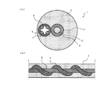
図1に、本発明の衝撃検知センサの一実施形態を示す。衝撃検知センサ1は、光ファイバ2と、光ファイバ2に巻き付けられたコードスイッチ3と、光ファイバ2及びコードスイッチ3を覆うモールド部4とを備えたものである。コードスイッチ3は光ファイバ2の周囲に長手方向に沿って螺旋状に巻き付けられている。
FIG. 1 shows an embodiment of the impact detection sensor of the present invention. The
光ファイバ2として、好適に、プラスチック光ファイバ(POF)、特に耐熱性プラスチックファイバ(HPOF)が使用できる。本実施形態では光ファイバ2としてHPOFを用いている。HPOF2は、光を伝搬するための断面円形のコア5と、コア5の外周を同心円状に覆う断面円筒形のクラッド6とから構成される。コア5の材料としては、耐熱性に優れた合成樹脂、例えば、アクリル樹脂、架橋アクリル樹脂(熱硬化アクリル樹脂)、シリコーン樹脂が用いられる。クラッド6の材料としては、耐熱性、耐水性、機械的特性に優れた合成樹脂、例えば、フッ化エチレンプロピレン樹脂などのフッ素樹脂が用いられる。HPOF2は、曲げや圧縮に応じて光伝送損失が生じる。なお、光ファイバ2としては、プラスチック光ファイバの他に、ガラス光ファイバを用いることができる。
As the
コードスイッチ3として、特再平9−21235号公報に記載されているコードスイッチを用いている。コードスイッチ3は、電極線8、中空絶縁体7からなる。電極線8は、所定の間隔を保ちながら復元性ゴム又は復元性プラスチックからなる中空絶縁体7の内面に沿って長手方向に螺旋状に配置されている。中空絶縁体7は、電極線8を電気的に接触しない状態で螺旋状に保持固定すると共に、外力により容易に変形し、外力がなくなれば直ちに復元するものである。電極線8は、銅線や銅合金などの金属導体や金属素線を複数本撚合せた金属撚線からなる。更に、電極線8は、復元性の向上および中空絶縁体3による電極線の保持固定力の向上をはかるため、金属導体線の外周に導電性ゴム層又は導電性プラスチック層を設けた構造としている。中空絶縁体7が外力によって変形すると電極線8同士が接触するので、予め電極線8に電圧を印加しておき、電圧や電流の変化から電極線8同士が短絡したことを検知することにより、コードスイッチ3の変形を検知するものである。なお、コードスイッチ3としては、本実施形態のものに限られるものでなく、光ファイバ2に巻き付けることができる可とう性を有し、巻き付けた状態でスイッチ機能を有するものであれば、他の形態のコードスイッチを用いることができる。
As the
モールド部4は光ファイバ2(本実施形態ではHPOF2)よりも柔らかい合成樹脂(例えば、シリコーンゴム)を用いて、HPOF2にコードスイッチを巻き付けたものの周囲にモールド成型して形成する。モールド部は断面略円形となるようにモールド成型する。なお、モールド部4の断面形状は、衝撃検知センサ1の応用に従って、楕円形、長円形などとしても良い。
The
図2に、本発明の衝撃検知センサを車両のバンパに敷設する時の図を示す。衝撃検知センサ1は、車両のバンパにU字状に折り曲げて敷設される。衝撃検知センサ1は、衝撃検知センサ1から剥き出したHPOF2の一端にLEDまたはLDからなる光源22が接続され、同様に剥き出したHPOF2の他端にPDからなる受光器23が接続される。光源22及び受光器23は、電線(電源線、接地線、信号線)24により図示しない衝撃解析装置に接続されている。また、コードスイッチ3から剥き出した電極線(図示せず)が圧力感知装置(図示せず)に接続されている。
FIG. 2 shows a view when the impact detection sensor of the present invention is laid on a bumper of a vehicle. The
次に、本発明の衝撃検知センサの動作を説明する。 Next, the operation of the impact detection sensor of the present invention will be described.
衝撃検知センサ1に衝撃が加わらない平常時は、HPOF2に伝送される光は曲げや歪みによる伝送損失はなく、コードスイッチ3の電極線8同士は互いに絶縁されている。
During normal times when no impact is applied to the
衝撃検知センサ1に衝撃が加わると、図3(a)及び図3(b)に示されるように、衝撃検知センサ1が長手方向のある領域において矢印で示す一方向からの荷重を受けて変形する。コードスイッチ3は荷重を受けて変形し、電極線8が短絡する。短絡による電圧や電流、抵抗値の変化が短絡信号として圧力感知装置に送られる。これにより、実際に衝撃検知センサ1に衝撃が加わったことを検知する。HPOF2にはコードスイッチ3が巻き付けてあるため、HPOF2にはコードスイッチ3による曲げ、歪みが生じる。この曲げ、歪みにより、衝撃に応じた光伝送損失が生じる。図4に示すように、HPOF2における透過光量は、衝撃が印加されたとき急激に減少し、その後、緩やかに減少して元の光量に戻る。衝撃解析装置は、透過光量の波形形状により、衝撃を与えた物体の性状、重さ、大きさなどを推定する。
When an impact is applied to the
次に、本発明の衝撃検知センサの作用を説明する。 Next, the operation of the impact detection sensor of the present invention will be described.
本発明の衝撃検知センサは、光ファイバを伝送する光の光量の変化より衝撃を検知できるとともに、コードスイッチを有しているので、別途誤動作防止用の感知センサを設けることなく、衝撃の印加の有無を検知できる。 The impact detection sensor of the present invention can detect an impact from a change in the amount of light transmitted through the optical fiber, and has a cord switch, so that it is possible to apply an impact without providing a separate sensor for preventing malfunction. Can detect presence or absence.
また、本発明の衝撃検知センサは可とう性を有しているため、折り曲げが容易であり、設置箇所への取り付け性に優れている。 Moreover, since the impact detection sensor of this invention has flexibility, it can be bent easily and is excellent in the attachment property to an installation location.
また、本発明の衝撃検知センサは、検知できる衝撃の印加方向が限定されない。 Further, in the impact detection sensor of the present invention, the application direction of the impact that can be detected is not limited.
また、本発明の衝撃検知センサは、コードスイッチを光ファイバに巻き付け、その外周にモールド部を形成するという構成を有しているので、長尺に製造することができ、コストの低減が可能である。 In addition, the impact detection sensor of the present invention has a configuration in which a cord switch is wound around an optical fiber and a mold part is formed on the outer periphery thereof, so that it can be manufactured in a long length and cost can be reduced. is there.
1 衝撃検知センサ
2 光ファイバ(例えば、HPOF)
3 コードスイッチ
4 モールド部
1
3
Claims (2)
上記プラスチック光ファイバの一端に接続された光源と、
上記プラスチック光ファイバの他端に接続された受光器と、
上記プラスチック光ファイバに巻き付けたコードスイッチと、
上記コードスイッチは、少なくとも2本の電極線が相互に電気的に接触しない状態で復元性ゴム又は復元性プラスチックからなる断面中空絶縁体の内面に沿って長手方向に螺旋状に配置されたコードスイッチであり、
上記プラスチック光ファイバと上記コードスイッチとを覆うモールド部と、
を備えたことを特徴とする衝撃検知センサ。 Plastic optical fiber,
A light source connected to one end of the plastic optical fiber;
A receiver connected to the other end of the plastic optical fiber;
A cord switch wound around the plastic optical fiber;
The cord switch is arranged in a spiral shape in the longitudinal direction along the inner surface of a cross-section hollow insulator made of a restoring rubber or a restoring plastic in a state where at least two electrode wires are not in electrical contact with each other. And
A mold part covering the plastic optical fiber and the cord switch;
An impact detection sensor comprising:
Priority Applications (1)
| Application Number | Priority Date | Filing Date | Title |
|---|---|---|---|
| JP2006008703A JP4809680B2 (en) | 2006-01-17 | 2006-01-17 | Impact detection sensor |
Applications Claiming Priority (1)
| Application Number | Priority Date | Filing Date | Title |
|---|---|---|---|
| JP2006008703A JP4809680B2 (en) | 2006-01-17 | 2006-01-17 | Impact detection sensor |
Publications (2)
| Publication Number | Publication Date |
|---|---|
| JP2007192567A JP2007192567A (en) | 2007-08-02 |
| JP4809680B2 true JP4809680B2 (en) | 2011-11-09 |
Family
ID=38448398
Family Applications (1)
| Application Number | Title | Priority Date | Filing Date |
|---|---|---|---|
| JP2006008703A Expired - Fee Related JP4809680B2 (en) | 2006-01-17 | 2006-01-17 | Impact detection sensor |
Country Status (1)
| Country | Link |
|---|---|
| JP (1) | JP4809680B2 (en) |
Families Citing this family (3)
| Publication number | Priority date | Publication date | Assignee | Title |
|---|---|---|---|---|
| DE102006031812A1 (en) * | 2006-07-07 | 2008-01-17 | Leoni Ag | Sensor system and sensor element |
| DE102006058785B4 (en) * | 2006-10-13 | 2019-03-21 | Fraba B.V. | Sensor for non-contact and tactile obstacle detection |
| CN112985655B (en) * | 2021-02-23 | 2023-06-09 | 富延升电子(福建)有限公司 | Pressure sensor capable of automatically recovering based on intelligent manufacturing |
Family Cites Families (11)
| Publication number | Priority date | Publication date | Assignee | Title |
|---|---|---|---|---|
| EP0082820A3 (en) * | 1981-12-21 | 1984-03-21 | Battelle Memorial Institute | Optical fibre pressure detector |
| US4488040A (en) * | 1982-11-19 | 1984-12-11 | Gte Products Corporation | Fiber optic sensor |
| SE443656B (en) * | 1984-07-20 | 1986-03-03 | Ericsson Telefon Ab L M | MICROBOOK LIKE OPTICAL FIBER CABLE |
| JPH01176618A (en) * | 1987-12-29 | 1989-07-13 | Fujitsu Ltd | Pressure detecting mat |
| DE3901845A1 (en) * | 1989-01-23 | 1990-07-26 | Felten & Guilleaume Energie | LIGHTWAVE LEAD SENSOR FOR SMALL TENSION OR PRESSURE FORCES |
| JPH07190872A (en) * | 1993-12-27 | 1995-07-28 | Nissei Denki Kk | Pressurization sensor |
| CA2211449C (en) * | 1995-12-04 | 2003-04-22 | Shigeru Kashiwazaki | Cord switch and pressure sensor |
| US5913003A (en) * | 1997-01-10 | 1999-06-15 | Lucent Technologies Inc. | Composite fiber optic distribution cable |
| JP2000036225A (en) * | 1998-07-21 | 2000-02-02 | Hitachi Cable Ltd | Cord switch |
| US6934426B2 (en) * | 2002-10-09 | 2005-08-23 | Senstar-Stellar Corporation | Fiber optic security sensor and system with integrated secure data transmission and power cables |
| JP4268528B2 (en) * | 2004-01-20 | 2009-05-27 | 日立電線株式会社 | Shock detection optical fiber sensor and system using the same |
-
2006
- 2006-01-17 JP JP2006008703A patent/JP4809680B2/en not_active Expired - Fee Related
Also Published As
| Publication number | Publication date |
|---|---|
| JP2007192567A (en) | 2007-08-02 |
Similar Documents
| Publication | Publication Date | Title |
|---|---|---|
| US9046671B2 (en) | Composite optical fiber cable and composite optical fiber cable assembly providing protection by flexure | |
| US7554045B2 (en) | Linear pressure sensor | |
| US9383532B2 (en) | Optical module | |
| KR101065115B1 (en) | Heat wire cable having structure for protecting wire | |
| CN103620466A (en) | Fiber optic cables allowing fiber translation to reduce bend attenuation | |
| JP4809680B2 (en) | Impact detection sensor | |
| JP5553032B2 (en) | Position sensor code, position sensor, and planar position sensor | |
| CN111584132A (en) | Wire harness | |
| JP4907346B2 (en) | Apparatus for monitoring electrical devices for disturbing arcs | |
| JP2004156945A (en) | Vehicle collision detector | |
| JP4436260B2 (en) | Fiber optic pressure sensor | |
| CN108574244B (en) | Cable anti-drop structure | |
| JP5920283B2 (en) | Composite cable | |
| JPH0829271A (en) | Pressure-sensitive sensor and its manufacture | |
| KR20080096446A (en) | An electric control cable | |
| US20220242336A1 (en) | Flat harness attachment structure, flat harness attachment component, and attachment component-equipped flat harness | |
| KR101520476B1 (en) | Partial discharge detector for power cable | |
| JP3591716B2 (en) | Snow melting equipment | |
| JP4268528B2 (en) | Shock detection optical fiber sensor and system using the same | |
| JP2000321151A (en) | Pressure sensor | |
| CN218330511U (en) | Signal transmission assembly and vehicle-mounted projection system | |
| JP6471639B2 (en) | Physical quantity measurement sensor | |
| JP5860801B2 (en) | Pressure detection cable | |
| JP6225074B2 (en) | Electric wire with terminal and manufacturing method thereof | |
| JP2013041814A (en) | Composite cable |
Legal Events
| Date | Code | Title | Description |
|---|---|---|---|
| A621 | Written request for application examination |
Free format text: JAPANESE INTERMEDIATE CODE: A621 Effective date: 20080310 |
|
| A977 | Report on retrieval |
Free format text: JAPANESE INTERMEDIATE CODE: A971007 Effective date: 20110311 |
|
| A131 | Notification of reasons for refusal |
Free format text: JAPANESE INTERMEDIATE CODE: A131 Effective date: 20110322 |
|
| A521 | Written amendment |
Free format text: JAPANESE INTERMEDIATE CODE: A523 Effective date: 20110509 |
|
| TRDD | Decision of grant or rejection written | ||
| A01 | Written decision to grant a patent or to grant a registration (utility model) |
Free format text: JAPANESE INTERMEDIATE CODE: A01 Effective date: 20110809 |
|
| A01 | Written decision to grant a patent or to grant a registration (utility model) |
Free format text: JAPANESE INTERMEDIATE CODE: A01 |
|
| A61 | First payment of annual fees (during grant procedure) |
Free format text: JAPANESE INTERMEDIATE CODE: A61 Effective date: 20110819 |
|
| FPAY | Renewal fee payment (event date is renewal date of database) |
Free format text: PAYMENT UNTIL: 20140826 Year of fee payment: 3 |
|
| R150 | Certificate of patent or registration of utility model |
Free format text: JAPANESE INTERMEDIATE CODE: R150 |
|
| LAPS | Cancellation because of no payment of annual fees |