JP4805251B2 - Improved processing method and apparatus for gas cluster ion beam - Google Patents
Improved processing method and apparatus for gas cluster ion beam Download PDFInfo
- Publication number
- JP4805251B2 JP4805251B2 JP2007504128A JP2007504128A JP4805251B2 JP 4805251 B2 JP4805251 B2 JP 4805251B2 JP 2007504128 A JP2007504128 A JP 2007504128A JP 2007504128 A JP2007504128 A JP 2007504128A JP 4805251 B2 JP4805251 B2 JP 4805251B2
- Authority
- JP
- Japan
- Prior art keywords
- pressure
- gas cluster
- ion beam
- cluster ion
- gas
- Prior art date
- Legal status (The legal status is an assumption and is not a legal conclusion. Google has not performed a legal analysis and makes no representation as to the accuracy of the status listed.)
- Active
Links
Images


Classifications
-
- H—ELECTRICITY
- H01—ELECTRIC ELEMENTS
- H01J—ELECTRIC DISCHARGE TUBES OR DISCHARGE LAMPS
- H01J27/00—Ion beam tubes
- H01J27/02—Ion sources; Ion guns
- H01J27/026—Cluster ion sources
-
- H—ELECTRICITY
- H01—ELECTRIC ELEMENTS
- H01J—ELECTRIC DISCHARGE TUBES OR DISCHARGE LAMPS
- H01J37/00—Discharge tubes with provision for introducing objects or material to be exposed to the discharge, e.g. for the purpose of examination or processing thereof
- H01J37/30—Electron-beam or ion-beam tubes for localised treatment of objects
- H01J37/305—Electron-beam or ion-beam tubes for localised treatment of objects for casting, melting, evaporating or etching
- H01J37/3053—Electron-beam or ion-beam tubes for localised treatment of objects for casting, melting, evaporating or etching for evaporating or etching
- H01J37/3056—Electron-beam or ion-beam tubes for localised treatment of objects for casting, melting, evaporating or etching for evaporating or etching for microworking, e.g. etching of gratings, trimming of electrical components
-
- H—ELECTRICITY
- H01—ELECTRIC ELEMENTS
- H01J—ELECTRIC DISCHARGE TUBES OR DISCHARGE LAMPS
- H01J2237/00—Discharge tubes exposing object to beam, e.g. for analysis treatment, etching, imaging
- H01J2237/06—Sources
- H01J2237/08—Ion sources
- H01J2237/0812—Ionized cluster beam [ICB] sources
-
- H—ELECTRICITY
- H01—ELECTRIC ELEMENTS
- H01J—ELECTRIC DISCHARGE TUBES OR DISCHARGE LAMPS
- H01J2237/00—Discharge tubes exposing object to beam, e.g. for analysis treatment, etching, imaging
- H01J2237/18—Vacuum control means
- H01J2237/188—Differential pressure
-
- H—ELECTRICITY
- H01—ELECTRIC ELEMENTS
- H01J—ELECTRIC DISCHARGE TUBES OR DISCHARGE LAMPS
- H01J2237/00—Discharge tubes exposing object to beam, e.g. for analysis treatment, etching, imaging
- H01J2237/30—Electron or ion beam tubes for processing objects
- H01J2237/31—Processing objects on a macro-scale
- H01J2237/3151—Etching
Description
本発明は、ガスクラスターイオンビームにより表面処理を行う方法および装置に関し、特に、表面処理効果が改善された、修飾ガスクラスターイオンビームの処理方法および装置に関する。 The present invention relates to a method and apparatus for performing surface treatment with a gas cluster ion beam, and more particularly to a method and apparatus for processing a modified gas cluster ion beam with improved surface treatment effect.
表面処理のためにクラスターイオンビームを使用することは公知である(例えば、米国特許5814194;デグチら)。ガスクラスターとは、標準温度と圧力下で気体状態である物質のナノサイズ集合体のことを言う。そのようなガスクラスターは典型的には緩く結束した数個から数千個の分子から成る集合体で構成されている。クラスターは電子衝撃等によってイオン化でき、制御可能なエネルギーを有する方向性ビームにすることができる。そのようなイオンは典型的には、それぞれがq×e(eは電荷であり、qは1以上の整数でクラスターイオンの荷電状態を表す)の正電荷を運搬する。非イオン化クラスターもまた、クラスターイオンビームの中に存在するかもしれない。大型クラスターイオンはしばしば最も有効である。なぜなら、クラスターイオン当たりのエネルギーを多量に運ぶことができるだけでなく、分子当たりのエネルギーは抑えることができるからである。クラスターは衝撃により分解し、個々の分子は全クラスターイオンのエネルギーのほんの一部を運搬しているだけである。その結果、大型クラスターイオンの衝撃効果は多大であるが、非常に浅い表面領域に限定される。このことから、クラスターイオンは様々な表面改質処理に有効利用でき、従来のモノマーイオンビーム処理による深い内層面の損傷を抑えることができる。 The use of cluster ion beams for surface treatment is known (eg, US Pat. No. 5,814,194; Deguchi et al.). A gas cluster refers to a nano-sized assembly of substances that are in a gaseous state at standard temperature and pressure. Such gas clusters are typically composed of aggregates of several to thousands of molecules that are loosely bound. The cluster can be ionized by electron impact or the like, and can be a directional beam having controllable energy. Each such ion typically carries a positive charge of q × e, where e is a charge and q is an integer greater than or equal to 1 and represents the charge state of the cluster ion. Non-ionized clusters may also be present in the cluster ion beam. Large cluster ions are often the most effective. This is because not only can a large amount of energy per cluster ion be carried, but also the energy per molecule can be suppressed. Clusters break down upon impact and individual molecules carry only a fraction of the energy of all cluster ions. As a result, the impact effect of large cluster ions is significant, but is limited to a very shallow surface area. Therefore, cluster ions can be effectively used for various surface modification treatments, and damage to the deep inner layer surface due to conventional monomer ion beam treatment can be suppressed.
ガスクラスターイオンビーム(以下GCIBという)の製造および加速方法は米国特許5814194に述べられている。ここでは、その内容を引用する。現在、利用可能なクラスターイオン源は多分散のサイズNを有するクラスターイオンを発生させる(Nは各クラスターイオンの分子数、アルゴンのような単原子ガスの場合には、単原子ガスは分子として扱い、そのような単原子ガスのイオン化された原子は、分子イオンまたは単にモノマーイオンとして扱う)。 A method for producing and accelerating a gas cluster ion beam (hereinafter GCIB) is described in US Pat. No. 5,814,194. Here, the content is quoted. Currently available cluster ion sources generate cluster ions having a polydisperse size N (N is the number of molecules in each cluster ion, and in the case of a monoatomic gas such as argon, the monoatomic gas is treated as a molecule. , Ionized atoms of such monoatomic gases are treated as molecular ions or simply monomer ions).
多くの有益な表面処理効果はGCIBsで表面を衝撃処理することにより達成される。これらの処理には限定されないが、洗浄、平滑化、エッチング、ドーピング、膜形成ないし膜成長などが含まれる。多くの場合、GCIB処理によって産業上の実用的な生産を達成するために、GCIB電流が数百から数千マイクロアンペア必要であることが知られている。GCIBの強度およびイオン化を増強する努力は、より高い電荷の状態のクラスター(q>1)の生産に向けられている。イオン化が電子衝撃によって行われるとき、ランダムな電子衝撃が進行する。非イオン化されたクラスターに対するイオン化されたクラスターの比率を高めるためには、電子衝撃が高くなければならず、その荷電状態の分布はおおよそ以下のポアソン統計式P(q)に近似する。 Many beneficial surface treatment effects are achieved by impact treating the surface with GCIBs. These treatments include, but are not limited to, cleaning, smoothing, etching, doping, film formation or film growth. In many cases, it is known that GCIB currents require hundreds to thousands of microamps to achieve practical industrial production by GCIB processing. Efforts to enhance the strength and ionization of GCIB are directed to the production of higher charge state clusters (q> 1). When ionization is performed by electron impact, random electron impact proceeds. In order to increase the ratio of ionized clusters to non-ionized clusters, electron bombardment must be high and its charge state distribution approximates the following Poisson statistical equation P (q).
(式1)

(式中、qは荷電、
![]()
![]()
このように、高くイオン化されたクラスタービームは、ビーム中に高度に荷電したクラスターイオンを含んでいる。たとえば、理論的にGCIBの95%の荷電状態が平均して3とすれば、8%以上が6以上の荷電を有する。しかし、そのような高荷電状態のクラスターは、荷電交換反応や、部分的に蒸発し得るので、荷電状態の分布やエネルギー分布が異なることとなり、実用的ビームにおいては正確な荷電状態、エネルギー分布を容易には予測できない。 Thus, a highly ionized cluster beam contains highly charged cluster ions in the beam. For example, if 95% of the charge state of GCIB is theoretically 3 on average, 8% or more has a charge of 6 or more. However, such highly charged clusters can partially evaporate due to charge exchange reactions, resulting in different charge state distributions and energy distributions. It is not easy to predict.
従来技術においては、イオンビームの最適な運搬は低圧力状態下に達成されると理解されている。また、産業上の経済的スケールにおいて、物質表面の効率的な処理のために通常必要とされる適度な高強度GCIBsが、ガスクラスターイオンの形で本質的な量のガスを標的部位に運搬されることも知られている。GCIBのガスクラスターイオンが標的に到達したとき、クラスターは分解して分子状のガスとして放出される。GCIBが標的部位に衝突し、ビーム全体のガス負荷が放出されるのである。アルゴンビームの有するビーム電流をIBとし、ガス流をF(sccm)とすると、ビームの運搬は下式により表される。 In the prior art, it is understood that optimal transport of the ion beam is achieved under low pressure conditions. Also, on an industrial economic scale, moderately high strength GCIBs that are normally required for efficient treatment of material surfaces can transport an essential amount of gas to the target site in the form of gas cluster ions. It is also known that. When the gas cluster ion of GCIB reaches the target, the cluster is decomposed and released as a molecular gas. The GCIB hits the target site and the entire beam gas load is released. A beam current having the argon beam and I B, when the gas flow and F (sccm), delivery of the beam is represented by the following formula.
(式2)
この式によれば、ビーム電流400μAでN/q比5000のとき、ビームは27sccmのガス流を運搬する。典型的なGCIB処理装置の場合には、このガス負荷に対する低圧環境維持のために、大容量、複数の真空ポンプが採用される。 According to this equation, when the beam current is 400 μA and the N / q ratio is 5000, the beam carries a gas flow of 27 sccm. In the case of a typical GCIB processing apparatus, a large capacity, multiple vacuum pumps are employed to maintain a low pressure environment against this gas load.
高強度GCIBsは多様な荷電状態のクラスターを含んでおり、加速電圧VAcc(数kV程度)で加速すると、ビームに対してq値が加わり、q・VAccの増加したエネルギーをもつクラスターが生成する。一般的に、対象物の表面をGCIBを用いて処理すると得られる多くの有益な効果は、ビーム内のガスクラスターイオンのエネルギーに依存している。たとえば、表面のエッチングは、高いエネルギーのクラスターを用いればより早く進行する。GCIB処理の他の有利な適用としては、表面のスムージング(平滑化)があり、他の方法に比べて原子或いは近原子レベルで優れた効果を示す。ある種のビーム状態におけるGCIBによる表面処理は、例外的平滑面を生じるが、GCIB処理が表面を常に平滑にするとは限らないことに留意すべきである。事実、初期表面が比較的平滑であるときは、GCIB処理により却って表面を荒らす場合もある。表面のエッチングやスムージングは、状況に応じて実施する。処理条件を最適化する通常の技術(たとえば、クラスターガス源の選択や、加速電圧の選択、GCIB電流の選択、GCIB処理方法の選択など)を使用するとき、すでに平滑な表面に対する、適度なエッチング速度(同時に進行するスムージング速度)や表面を荒らさないようにする適当なGCIBビームの条件がしばしば見つからない。GCIB処理による進取的なエッチング速度は、通常高エネルギー、高強度のGCIB状態を必要とするが、表面を荒らさず平滑化するためには、低いエネルギーの(もしくはエッチングのためには実用的ではない状態の)ビームが望ましいことも知られているのである。そのような場合、所望の目的を達成するためにいくつかのGCIBステップを組み合わせることが必要であった。そのようなプロセスとしては、最初のビーム状態を進取的(aggressive)なエッチングができる条件、次いで最初のエッチングにより生じた荒さを減少させるようなエッチング条件、そしてエッチングが生じないがスムージングできるような条件による他のステップを適用する。そのようなステップの組み合わせもしくは複合化は、期待される最終的な結果には到達していないけれども、ある重要なプロセスにおいて低い生産性ではあるが技術的には知られている。たとえば、フェンナーらの米国特許6375790には、多段階の処理をGCIB処理装置に適用させて、そのような複合処理が可能であることを開示している。 High-intensity GCIBs contain clusters in various charged states. When accelerated with an acceleration voltage V Acc (about several kV), a q value is added to the beam, and a cluster with increased energy of q · V Acc is generated. To do. In general, many beneficial effects obtained when treating the surface of an object with GCIB depend on the energy of gas cluster ions in the beam. For example, surface etching proceeds faster using high energy clusters. Another advantageous application of the GCIB process is surface smoothing, which exhibits superior effects at the atomic or near-atom level compared to other methods. It should be noted that surface treatment with GCIB in certain beam conditions produces exceptional smooth surfaces, but GCIB treatment does not always smooth the surface. In fact, when the initial surface is relatively smooth, the surface may be roughened by GCIB treatment. Surface etching or smoothing is performed according to the situation. Moderate etching on already smooth surfaces when using conventional techniques to optimize processing conditions (eg, cluster gas source selection, acceleration voltage selection, GCIB current selection, GCIB processing method selection, etc.) Frequently, the conditions for smoothing speed (simultaneous smoothing speed) and the appropriate GCIB beam to keep the surface rough are not found. The progressive etch rate by GCIB treatment usually requires a high energy, high strength GCIB state, but low energy (or impractical for etching) to smooth the surface without roughening It is also known that a beam of state is desirable. In such cases, it was necessary to combine several GCIB steps to achieve the desired purpose. Such processes include conditions that allow progressive etching of the initial beam state, then etching conditions that reduce the roughness caused by the initial etching, and conditions that do not cause etching but can be smoothed. Apply other steps by Such a combination or combination of steps is known in the art, albeit at low productivity in certain critical processes, although the expected final result has not been reached. For example, U.S. Pat. No. 6,375,790 to Fenner et al. Discloses that multi-stage processing can be applied to a GCIB processing apparatus to allow such combined processing.
GCIBの形成にイオン化ガスクラスターの生産に有効なイオナイザーを適用すると、広い範囲のイオン化された状態のビームが得られるが、これらは対象物のGCIB処理による高生産性が求められる場合に必要な強力なビーム(式1で示すような)の生産条件では、特にマルチイオン化されたガスクラスターが含まれている。そのようなビームに、適度なエッチング速度を得るためのエネルギーを与えるのに十分な状態で加速されると、表面のスムージングだけでなく、表面を荒らす方向にも作用する。この問題は、GCIBプロセスの複合化または多段階化によって少なくとも軽減はされるが、所望の速度での生産性を上げてはいない。さらに、多くの異なるビーム状態を有する複合化処理であっても、究極レベルの平滑化は得られておらず、他の重要な処理方法が必要とされているのである。 Applying an ionizer that is effective in producing ionized gas clusters for the formation of GCIB results in a wide range of ionized beams, which are necessary for high productivity of GCIB processing of objects. In particular, the production conditions for such a beam (as shown in Equation 1) include multi-ionized gas clusters. When such a beam is accelerated in a state sufficient to give energy for obtaining a suitable etching rate, it acts not only on the surface smoothing but also in the direction of roughening the surface. This problem is at least mitigated by the GCIB process complexation or multi-stage, but does not increase productivity at the desired rate. Furthermore, even complex processing with many different beam states does not provide the ultimate level of smoothing, and other important processing methods are needed.
上述の通り、本発明の目的は、良好なエッチング能力だけでなく良好なスムージング能力を有するビームを形成する特徴を有するGCIBの修飾方法を提供することを目的とする。 As described above, an object of the present invention is to provide a method for modifying GCIB having a characteristic of forming a beam having not only good etching ability but also good smoothing ability.
本発明の他の目的は、より表面のスムージング能力が改善されたビームを形成する特徴を有するGCIBの修飾方法を提供することを目的とする。 It is another object of the present invention to provide a method for modifying GCIB having the characteristics of forming a beam with improved surface smoothing ability.
本発明のさらに別の目的は、対象物を高いエッチング速度で、究極の平滑面を形成するための能力を有するGCIBを修飾する装置を提供することを目的とする。 Yet another object of the present invention is to provide an apparatus for modifying GCIB that has the ability to form an ultimate smooth surface on an object at a high etch rate.
そしてまた、他の目的は、より表面のスムージング能力が改善されたGCIBの製造装置であって、GCIBを修飾する装置を提供することを目的とする。 Another object of the present invention is to provide a GCIB manufacturing apparatus having a further improved surface smoothing ability, which modifies the GCIB.
そして、これらの目的は本発明における、GCIBの形成の間に環境圧力およびその幾何学的コントロールによって達成された。 And these objects were achieved in the present invention by the environmental pressure and its geometric control during the formation of GCIB.
本発明の理解を助けるため、以下に図面を参照しつつ説明する。 In order to facilitate understanding of the present invention, the following description will be given with reference to the drawings.
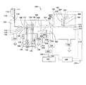
図1は従来技術による典型的なGCIB処理装置100の基本構成を示す概略図である。この装置の真空容器102は3つの連通チャンバーであるビーム源チャンバ104、イオン化/加速チャンバ106および処理チャンバ108に分割されている。これらの3つのチャンバはそれぞれ真空ポンプシステム146a、146bおよび146cで適当な作動圧に減圧されている。ガス保存シリンダ111に保存された濃縮性ガス112(たとえばアルゴンまたはN2)はガス測定バルブ113とガス供給チューブ114を介して滞留チャンバ116に圧力下で送られ、適当な形状のノズル110を介して低圧の真空チャンバ内に放出される。そこで超音速ガスジェット118が発生する。ジェット流の膨張により冷却され、ガスジェット118の一部がクラスターに濃縮される。それぞれのクラスターは数個から数千個の弱い結合原子または分子で構成される。高圧が有害である下流領域(たとえばイオナイザー122、高電圧電極126、処理チャンバ108)で圧力を最小にするために、クラスタージェットから、クラスタージェットに濃縮されなかったガス分子を、ガススキマー開口部120が部分的に分離する。ここで適当な濃縮性ガス112は、限定されないが、アルゴン、窒素、二酸化炭素、酸素、その他のガスおよびガス混合物である。
FIG. 1 is a schematic diagram showing a basic configuration of a typical
ガスクラスターを含んだ超音速ガスジェット118が形成された後に、クラスターはイオナイザー122内でイオン化される。イオナイザー122は典型的には電子衝撃型イオナイザーであり、1以上の白熱フィラメント124から熱電子を発生させ、電子を加速および指向させて、イオナイザー122をジェットが通過する際にガスジェット118内のガスクラスターと衝突させる。電子衝撃によって電子がクラスタから飛び出し、クラスターの一部が正にイオン化される。またあるクラスターは2個以上の電子を放出し、多重イオン化(multiply ionized)される。適切にバイアスされた高電圧電極126のセットはイオナイザーからクラスターイオンを抽出して、ビームを形成および加速して所望のエネルギー(典型的には数百Vから数百kVあるいはそれ以上)を与え、それらを合焦(focuses)させてGCIB128を形成させる。フィラメント電源136は、フィラメントに電圧Vfを与え、イオナイザーフィラメント124を加熱する。アノード電源134はアノード電圧VAを与えフィラメント124から飛び出す熱電子を加速してクラスター含有ガスジェット118を照射してイオンを発生させる。導出電源138は導出電圧VEを与え高電圧電極をバイアスしてイオナイザー122のイオン化領域からイオンを導出し、GCIB128を形成する。加速電源140は加速電圧VAccを与え、イオナイザー122に関する高電圧電極をバイアスし、全GCIB加速ポテンシャルをVAccと等しくする。一以上のレンズ電源(142、144など)が与えられ、焦点電位(VL1、VL2など)の高電圧電極をバイアスしてGCIB128を焦点させる。
After the
GCIBで処理される半導体ウェハーまたは他の対象物である対象物152は対象物ホルダー150に保持され、GCIB128の通路内に配置される。ほとんどの適用形態では、大型対象物を空間的に均質に処理することを期待するので、スキャン処理システムは空間的に同種の結果を生じるように大きなエリアでGCIB128を均質にスキャンすることが望ましい。
An
GCIB128は変化せず、軸129を有し、対象物152はその表面をGCIB128によって効果的に処理するために機械的にスキャンされる。Xスキャンアクチュエーター202は対象物ホルダー150に直線運動を与え、紙面に対して垂直方向への動作208を行う。Yスキャンアクチュエーター204は対象物ホルダー150に同様に直線運動を与え、Xスキャン動作208に直交するようにYスキャン動作210の方向へ動かす。XスキャンとYスキャン動作の組み合わせによって、対象物ホルダー150に保持された対象物152が動かされ、GCIB128を通してラスターの様な(raster- like)なスキャン動作をすることにより、GCIB128による対象物128表面の均質な(もしくはプログラムされた)照射が行われる。対象物152をGCIB128の軸に対して傾斜して、対象物ホルダー150に保持することにより対象物152の表面に対するビーム入射角206を持たせる。ビーム入射角206は通常90度もしくはそれ以外の角度であってよく、典型的には90度または90度近辺である。Yスキャン処理の間に、対象物ホルダー150に保持された対象物152は152Aと150Aで示された位置を交互に移動する。これら2つの位置間での移動中に対象物152がGCIB128のスキャンを受け、両端の位置においてはGCIB128の通路から完全にはずれている(オーバースキャン)ことが分かる。図1には明確に示されてはいないけれども、Xスキャン動作の方向208(紙面に対して垂直方向)に対しても同様にスキャンおよびオーバースキャンがされているのである。
The
ビーム電流センサ218はGCIB128の通路の対象物ホルダー150の後ろに設けられ、対象物ホルダー150がGCIB128の通路をスキャンアウトされたときGCIB128のサンプルをとらえる(intercept)。ビーム電流センサ218は典型的にはファラデーカップなどであり、ビームの入射口を除いて閉じられており、電気絶縁マウント212で真空容器102の壁に固定されている。
A beam
マイコンベースのコントローラ220はXスキャンアクチュエーター202とYスキャンアクチュエーター204に電気的ケーブル216を介して接続され、両アクチュエーターを制御して対象物152がGCIB128の内外に出入りさせ、GCIB128に対して均一的にスキャンし、GCIB128による対象物152の適切な処理を実現する。コントローラ220はリード214を介してビーム電流センサ218で集められるビーム電流のサンプルを受信し、GCIBをモニターし、所定のGCIB照射量が投射されたときにGCIB128から対象物152を取り除くことによりGCIBの照射量を制御する。
The microcomputer-based
図2は本発明の具体例としてGCIB処理装置300の概略を示す。調節壁(baffle)302(複数の調節板を用いても良いが、例では簡略化するために一枚の板のみ示している)は分離された圧力チャンバ304を形成し、イオン化/加速化チャンバ106および処理チャンバ108の圧力よりも高い圧力を加えることができる。
FIG. 2 schematically shows a
イオン化/加速化チャンバ106はGCIB128を圧力チャンバ304へ導入するためのイオン化/加速化チャンバ開口部306を有している。調節壁302は、圧力チャンバ304からGCIB128の出口となる圧力チャンバ開口部308を有する。圧力チャンバ304を通過するGCIB128は、その通路D1に沿った、長さd1を有する。また調節壁302は、処理チャンバ108に対して1以上の開口部310を有していてもよい。圧力チャンバから処理チャンバ108通じるこの圧力チャンバ開口部308および付加的な開口部310は、トータルのガスコンダクタンスCPを有する。イオン化/加速化チャンバ306のガスコンダクタンスはCAである。圧縮ガス314はガス保存シリンダ312内に保存されている。圧縮ガス314は好ましくは不活性ガスであり、好適にはアルゴンである。ガス計測バルブ316は好ましくはマスフローコントロールタイプの計測バルブであり、ガス供給チューブ318およびディフューザ320を通して圧力チャンバ304に圧縮ガス314を調整しつつ流している。圧力チャンバ304に導入されたガス314は、イオン化/加速化チャンバ106および処理チャンバ108の基礎圧力と比較して、圧力チャンバ304内を加圧する。
The ionization /
QINはディフューザ320を通して圧力チャンバ304内に流れ込むガス流量を示す。
QAは圧力チャンバ304とイオン化/加速化チャンバ106の間のイオン化/加速化チャンバ開口部306を通る流量を示す。
QPは圧力チャンバ304と処理チャンバ108の間の圧力チャンバ開口部308および開口部310を通る流量を示す。
PCは圧力チャンバ304内の真空圧を示し、
PPは処理チャンバ108内の真空圧を示し、(図2には示されてはいないが)通常の真空圧ゲージを用いて測定した値であり、
PAはイオン化/加速化チャンバ106内の真空圧を示し、前記同様に測定した値である。
前記を用いて以下の式にて表すことができる。
Q IN indicates the flow rate of gas flowing into the
Q A indicates the flow rate through the ionization / acceleration chamber opening 306 between the
Q P represents the flow rate through the pressure chamber opening 308 and the
P C denotes the vacuum pressure in the
P P represents the vacuum pressure in the
P A represents the vacuum pressure in the ionization /
Using the above, it can be expressed by the following formula.
コンダクタンスCAおよびCPは計算もしくは経験上決定でき、QINはガス計測バルブ316(好ましくはマスフローコントロールバルブ)によって制御できる。またPCおよびPAは通常の真空圧センサを用いて測定できるから、式5(もしくは式6の条件が満たされれば式7)を使用することによって、PCが既知量として表されるので、ガス計測バルブ316の調整により容易に制御することができる。
Conductance C A and C P can be determined on the calculation or experience, Q IN gas metering valve 316 (preferably a mass flow control valve) can be controlled by. Also since the P C and P A can be measured using a conventional vacuum pressure sensor, (if satisfied condition or Formula 6 Formula 7)
また、任意に、圧力センサ322は圧力チャンバ304の中に設けることもできる。圧力センサ322はケーブル324によって圧力コントローラおよび読み出し表示装置326とつながっている。圧力コントローラと読み出し表示装置326は圧力チャンバ304内の圧力を直接読み取る。
Optionally, the
圧力チャンバ304はPAおよびPPより高い圧力PCを有する。GCIB128は高圧の圧力チャンバー304を通過するので、以下に示されるように、GCIBの特性はその処理の適合性を向上させる方向で修飾される。GCIBの修飾の程度は圧力PCおよび圧力チャンバ304内のGCIBの通過距離d1に関係がある。より明確には、PCがGCIB通路D1に沿ってほぼ一定の時は、GCIB特性の修飾程度は、圧力PCと距離d1の積に(PCd1)に関係する。圧力チャンバ内の圧力PCが通路D1に沿っていくらかの空間的変化を持っているときは、GCIB特性の修飾程度は、通路D1(圧力−距離のインテグラル(PDI))に沿って、0からd1までの積分(PC(x)・dx)に関係する。圧力−通路距離の積および/またはPDIは共に単位(torr・cm)として表すことができる。
The
図3は本発明の第二の具体例であるGCIB処理装置350を表す概略図である。圧縮ガス314はガス保存シリンダ312内に保存されている。圧縮ガス314はたとえばアルゴンのような不活性ガスが好ましい。マスフローコントロールバルブ352は、圧力チャンバ304内のガス供給チューブ318およびディフューザ320を通る圧縮ガス314の流れを制御する。マイクロプロセッサベースのプログラム可能な多目的コントローラ358は、GCIB処理装置350の部分的ないし全体の制御に用いられ、圧力センサ322からケーブル324、圧力センサコントローラおよび読み出し表示装置326、ケーブル360を通して圧力チャンバ304内の圧力測定信号を受信する。コントローラ358はまたケーブル360、マスフローコントローラ356、ケーブル354を通してマスフローコントロールバルブ352を制御し、圧力チャンバ304内へのガス314の流入をセットし調整する。圧力センサ322からの圧力測定信号が利用されるかどうかに応じて、コントローラ358は開ループもしくは閉ループの制御アルゴリズムによる圧力チャンバ304内の圧力PCを制御する能力を有する。コントローラ358は他のセンサからの信号も受信し、ケーブル360を通してGCIB処理装置350の総合制御の一部として他のシステムへ制御信号を送信する。これら他の接続は識別子(identifier)362によって表される。
FIG. 3 is a schematic diagram showing a
図4は本発明の第三の具体例であるGCIB処理装置400を表す概略図である。イオン化/加速化チャンバ106と処理チャンバ108は互いに連通しており、実質的に同じ圧力PP2を有する。圧力セル402は、PP2よりも高い圧力PC2を、その圧力セル内部408においてかけることができる。圧力セル402は圧力セル入口開口部404と圧力セル出口開口部406を有する。GCIB128は開口部404を通って圧力セル402内に入り開口部406を通って圧力セルから出る。圧力セル402を通るGCIB128の通路D2は、長さd2を有する。圧力セル入り口404と出口406はトータルガスコンダクタンスCP2を有する。圧縮ガス314は、ガス保存シリンダ312内に保存されている。圧縮ガス314はたとえばアルゴンのような不活性ガスが好ましい。マスフローコントロールバルブ352は、ガス供給チューブ318およびディフューザ410を通って圧力セル402内への圧縮ガス314の流入を制御する。この具体例における多目的コントローラ358もまた、マイクロプロセッサベースのプログラム可能であり、GCIB処理装置400の部分的ないし全体の制御に用いられ、ケーブル324、圧力センサコントローラおよび読み出し表示装置326、ケーブル360を通して圧力センサ412から測定圧力信号をPP2として受信する。コントローラ358はまた、ケーブル360、マスフローコントロールバルブコントローラ356、ケーブル354を通してマスフローコントロールバルブ352を制御し、圧力チャンバ304内のガス314の流れをセットし調整する。圧力センサ412からの圧力測定信号が利用されるかどうかに応じて、コントローラ358は開ループもしくは閉ループの制御アルゴリズムによる圧力セル402内の圧力PC2を制御する能力を有する。本発明に式12を適用することにより実施可能であるので、圧力PP2を測定することは必ずしも不可欠ではない。コントローラ358は他のセンサからの信号も受信し、ケーブル360を介してGCIB処理装置350の総合制御の一部として他のシステムへ制御信号を送信する。これら他の接続は識別子362によって表される。
FIG. 4 is a schematic diagram showing a
QIN2はディフューザ410を通して圧力セル402内に流れ込むガス流量を示す。
QP2は処理チャンバ108とイオン化/加速化チャンバ106の間にある圧力セル402の、入口404から出口406を通して全体の流量を表す。
PC2は圧力セル402内の真空圧を示し、
PP2は処理チャンバ108およびイオン化/加速化チャンバ106内の真空圧を示し、圧力センサ412を用いて測定した値である。
前記を用いて以下の式にて表すことができる。
Q IN2 indicates the gas flow rate that flows into the
QP2 represents the overall flow rate of the
P C2 represents the vacuum pressure in the
P P2 indicates the vacuum pressure in the
Using the above, it can be expressed by the following formula.
コンダクタンスCP2は計算もしくは経験上決定でき、QIN2はマスフローコントロールバルブ352によって制御される。またPP2は、圧力センサ412を用いて測定でき、式10(もしくは式11の条件が満たされれば式12)として示される。さらにPC2は既知の量として表され、マスフローコントロールバルブ352を調整することによって、容易に制御することができる。
Conductance C P2 can be determined on the calculation or experience, Q IN2 is controlled by the mass
運転中は、圧力セル402はPP2よりも高い圧力で操作される。GCIB128が圧力が上昇した圧力セル402を通るときに、GCIBの特徴が修飾されて、ある種のGCIB処理の適合性を向上させるように改善される。GCIBの特徴が修飾される程度は、圧力PC2に関連し、圧力セル402中のGCIB通路の長さd2に関連する。さらに明確には、PC2は、GCIB通路D2に沿っておおよそ一定である場合、GCIBの特徴を修飾する程度は、圧力PC2と長さd2の積(PC2・d2)に依存する。また圧力セル内の圧力PC2が通路D2に沿って空間的に変化する場合には、GCIB特性の修飾程度は通路D2に沿って、0からd1までの積分(PC2(x)・dx)(圧力−距離のインテグラル(PDI))に関係する。圧力と通路長さの積および/またはPDIはともに、単位(torr・cm)として表すことができる。
During operation,
図5はケースAからGまで圧力セル内の圧力条件を変化させてGCIB特性を測定した結果を示すグラフである。オリジナルGCIBは30kVの電位差によって加速されたアルゴンガスクラスターイオンビームである。グラフは、ガスクラスターイオンの分布(縦軸、任意の単位)と対するガスクラスターイオンエネルギーを電荷で割った値(横軸、keV/q)をプロットしたものである。ケースAからGまでは、圧力セルのPDI値を1.0×10−4から1.3×10−3torr-cmまで変化させたものである。ケースAの1.0×10−4torr-cmでは、実質的に圧力セルがほとんど無いに等しいケースであるが、ガスクラスターイオンエネルギーは22keV/q近傍に狭いピークを示している。PDI値を上げると、分布が広がってエネルギー分布のピークが低い方に動いていく。このようなエネルギー分布の修飾は単にビーム加速電位を下げることによって(本発明を用いないで)は得られない。より大きなPDI値から得られるこのような分布は、GCIBに高いスムージング性能を与え、低いエッチングの速度を与える。 FIG. 5 is a graph showing the results of measuring GCIB characteristics by changing the pressure conditions in the pressure cell from cases A to G. The original GCIB is an argon gas cluster ion beam accelerated by a potential difference of 30 kV. The graph plots the value (horizontal axis, keV / q) obtained by dividing the gas cluster ion energy by the charge against the distribution of gas cluster ions (vertical axis, arbitrary unit). In cases A to G, the PDI value of the pressure cell is changed from 1.0 × 10 −4 to 1.3 × 10 −3 torr-cm. In case A, 1.0 × 10 −4 torr-cm, which is substantially equal to almost no pressure cell, the gas cluster ion energy shows a narrow peak in the vicinity of 22 keV / q. When the PDI value is increased, the distribution spreads and the peak of the energy distribution moves toward the lower side. Such modification of the energy distribution cannot be obtained simply by lowering the beam acceleration potential (without using the present invention). Such a distribution resulting from a larger PDI value gives GCIB a high smoothing performance and a low etch rate.
図6はPDI値に対するGCIBのエッチング速度を示したグラフである。この場合の対象物はSiO2表面を有し、30kVの加速電圧によってアルゴンGCIBを加速して処理され、3×10¹⁵のガスクラスターイオン/cm2の全量で照射されたものである。エッチング速度はPDI値が増加するに従ってゆっくりと低下し、高いPDI値になると速度低下が急激におこり、そしてほぼゼロに近づく。 FIG. 6 is a graph showing the etching rate of GCIB with respect to the PDI value. The object in this case has an SiO 2 surface, is processed by accelerating argon GCIB with an acceleration voltage of 30 kV, and irradiated with a total amount of 3 × 10 15 gas cluster ions / cm 2 . The etching rate slowly decreases as the PDI value increases, and at a high PDI value, the rate decreases rapidly and approaches almost zero.
図7はPDI値に対する処理後の表面粗度を原子間力顕微鏡を用いて測定したグラフである。この場合の対象物はSiO2表面を有し、30kVの加速電圧によってアルゴンGCIBを加速して処理され、3×10¹⁵のガスクラスターイオン/cm2の全量で照射されたものである。低いPDI値では、PDI値が増加するに従って急激に荒さが解消され、高いPDI値になると粗度が低レベルで落ちついて、さらなる効果増進はない。 FIG. 7 is a graph obtained by measuring the surface roughness after treatment with respect to the PDI value using an atomic force microscope. The object in this case has an SiO 2 surface, is processed by accelerating argon GCIB with an acceleration voltage of 30 kV, and irradiated with a total amount of 3 × 10 15 gas cluster ions / cm 2 . At a low PDI value, the roughness is abruptly eliminated as the PDI value increases, and at a high PDI value, the roughness falls to a low level and there is no further effect enhancement.
図6および7についてはSiO2のエッチングおよび平滑化について示した。しかし、同様な結果は他の材料であっても得られ、たとえば金属や、酸化物、セラミックス、半導体、などにおいても同様である。PDI(または圧力−通路長の積)が5×10⁻⁴torr-cmより大きいと、(表面が荒らされることなしに)有意な平滑化が達成され、エッチング速度の減少も少ない。高いエッチング速度ならびに、優れた平滑化および/または表面が荒らされることのない処理は、従来のGCIB源の調整や、加速化電圧の調整によっては得られないことが多い。PDI値を高めることによって、エッチング速度が次第に低下するが、高度な平滑化が得られる。高いPDI値においては、従来のGCIB源の調整によっては得られなかったレベルの平滑化が多くの物質において得られるのである。 6 and 7 show the etching and smoothing of SiO 2 . However, similar results can be obtained with other materials, such as metals, oxides, ceramics, and semiconductors. If the PDI (or pressure-passage length product) is greater than 5 × 10 −4 torr-cm, significant smoothing is achieved (without surface roughening) and the etch rate is reduced less. High etch rates and excellent smoothing and / or surface-roughening treatments are often not obtained by conventional GCIB source adjustments or acceleration voltage adjustments. By increasing the PDI value, the etching rate gradually decreases, but a high degree of smoothing can be obtained. At high PDI values, a level of smoothing not obtainable by adjusting the conventional GCIB source is obtained in many materials.
以上、本発明を種々な具体例を示して説明したが、本発明の思想の範囲内でそのほかの様々な改良・改善が可能であると理解されるべきである。 Although the present invention has been described with reference to various specific examples, it should be understood that various other improvements and improvements can be made within the scope of the idea of the present invention.
Claims (23)
減圧された減圧チャンバと、
ガスクラスターイオンビーム通路を有する高エネルギーガスクラスターイオンビーム発生のための、前記チャンバ内のガスクラスターイオンビーム源と、
前記減圧チャンバ内の、減圧を上回る平均圧力を有する圧力コントロール領域と、
を含んで構成され、
前記ガスクラスターイオンビーム通路の少なくとも一部が、前記圧力コントロール領域を通ることによって、前記圧力コントロール領域のより高い圧力により修飾されることを特徴とする装置。A generator of gas cluster ion beam,
A decompressed vacuum chamber;
A gas cluster ion beam source in the chamber for generating a high energy gas cluster ion beam having a gas cluster ion beam path;
A pressure control region having an average pressure of the decompression chamber, above the vacuum
Comprising
Device at least a portion of said gas cluster ion beam passage, by passing through the pressure control region, characterized in that it is modified by a higher pressure in the pressure control region.
加圧されたガス源と、
前記減圧チャンバ内に前記加圧ガス源からの加圧ガスを導入してガスクラスターを形成するノズルと、
ガスクラスターをイオン化させてガスクラスターイオンビームを形成するイオナイザーと、
前記ガスクラスターイオンビームを加速して前記高エネルギーガスクラスターイオンビームを形成するアクセラレータとを含んで構成されている請求項1記載の装置。The gas cluster ion beam source further comprises:
A pressurized gas source;
A nozzle for forming a gas cluster by introducing a pressurized gas from the pressurized gas source into the vacuum chamber,
An ionizer that ionizes the gas cluster to form a gas cluster ion beam;
The apparatus according to claim 1, further comprising an accelerator that accelerates the gas cluster ion beam to form the high energy gas cluster ion beam.
前記圧力コントロール領域が圧力チャンバを含み、
前記圧力チャンバが前記イオン化/加速化チャンバよりも高圧であることを特徴とする請求項1記載の装置。 The decompression chamber has an ionization / acceleration chamber containing the gas cluster ion beam source,
The pressure control region includes a pressure chamber;
The apparatus of claim 1, wherein the pressure chamber is at a higher pressure than the ionization / acceleration chamber.
前記圧力チャンバが前記処理チャンバよりも高圧であることを特徴とする請求項7記載の装置。 The vacuum chamber further comprises a processing chamber;
The apparatus of claim 7, wherein the pressure chamber is at a higher pressure than the process chamber.
ガスクラスターをガスクラスターイオンビームにイオン化するイオナイザーと、
ガスクラスターイオンビームを高エネルギーガスクラスターイオンビームに加速するアクセラレータと、
を含む請求項9記載の装置。 The gas cluster ion beam source further has the following configuration,
An ionizer that ionizes the gas cluster into a gas cluster ion beam;
And accelerator for accelerating the gas cluster ion beam with high energy gas cluster ion beam,
The apparatus of claim 9 comprising:
減圧チャンバ内のガスクラスターイオンビーム源からガスクラスターイオンビームを発生させる工程と、
高エネルギーガスクラスターイオンビームを形成するために、ビーム通路を有するアクセラレータにより前記ガスクラスターイオンビームを加速する工程と、
減圧チャンバ内に対象物を保持する工程と、
アクセラレータと対象物の間に加圧領域を提供し、前記ビーム通路の少なくとも一部が前記加圧領域を通過する工程と、
を含むことを特徴とする処理方法。A method of processing an object with a gas cluster ion beam ,
A step of generating a gas cluster ion beam from a gas cluster ion beam source within the vacuum chamber,
In order to form a high energy gas cluster ion beam, the steps of accelerating the gas cluster ion beam by accelerator having a beam path,
A step of holding an object in a vacuum chamber,
A step of providing a pressure area between the accelerator and the object, at least a portion of said beam path passes through the press section,
The processing method characterized by including.
ノズルを提供する工程と、
前記加圧ガス源から前記減圧チャンバへ導入することによってガスクラスターを形成するために、加圧ガスを前記ノズルから放出する工程と、
イオナイザーを提供する工程と、
ガスクラスターをガスクラスターイオンビームへイオン化する工程と、
をさらに含む請求項14記載の方法。Providing a source of pressurized gas,
Providing a nozzle,
A step of releasing in order to form a gas cluster, the pressurized gas from the nozzle by introducing into the vacuum chamber from the pressurized gas source,
Providing a ionizer,
And ionizing the gas cluster to a gas cluster ion beam,
15. The method of claim 14, further comprising:
前記システムにより前記加圧領域の圧力をコントロールする工程と、
をさらに含む請求項14記載の方法。Providing a system for controlling the pressure in the pressurizing region,
A step of controlling the pressure of the pressure area by the system,
15. The method of claim 14, further comprising:
減圧チャンバ内のガスクラスターイオンビーム源からガスクラスターイオンビームを発生させる工程と、
前記ガスクラスターイオンビームを、ビーム通路およびエネルギー分布を有するガスクラスターイオンを含む高エネルギーガスクラスターイオンを形成するために、減圧チャンバ内のアクセラレータにより加速する工程と、
減圧チャンバ内に加圧領域を供給する工程と、
ガスクラスターイオンビーム通路の少なくとも一部が前記加圧領域を通過するように、高エネルギーガスクラスターイオンのビーム通路を導く工程と、
ガスクラスターイオンビームを生成する工程と、
を含む方法。 A method for providing an accelerated gas cluster ion beam comprising :
A step of generating a gas cluster ion beam from a gas cluster ion beam source within the vacuum chamber,
Said gas cluster ion beam, in order to form a high energy gas cluster ions containing gas cluster ions having a beam path and energy distribution, comprising the steps of accelerating the accelerator in the decompression chamber,
And providing a pressure area in a vacuum chamber,
Such that at least a portion of the gas cluster ion beam path passes through the press section, the step of directing the beam path of the high energy gas cluster ions,
Generating a gas cluster ion beam,
Including methods.
前記加圧領域の圧力をコントロールする工程と、
をさらに含む請求項19記載の方法。Providing a system for controlling the pressure in the pressurizing region,
A step of controlling the pressure of the pressure region,
20. The method of claim 19, further comprising:
Applications Claiming Priority (3)
| Application Number | Priority Date | Filing Date | Title |
|---|---|---|---|
| US55481204P | 2004-03-19 | 2004-03-19 | |
| US60/554,812 | 2004-03-19 | ||
| PCT/US2005/008983 WO2005091990A2 (en) | 2004-03-19 | 2005-03-18 | Method and apparatus for improved processing with a gas-cluster ion beam |
Publications (3)
| Publication Number | Publication Date |
|---|---|
| JP2007529876A JP2007529876A (en) | 2007-10-25 |
| JP2007529876A5 JP2007529876A5 (en) | 2011-07-07 |
| JP4805251B2 true JP4805251B2 (en) | 2011-11-02 |
Family
ID=35056718
Family Applications (1)
| Application Number | Title | Priority Date | Filing Date |
|---|---|---|---|
| JP2007504128A Active JP4805251B2 (en) | 2004-03-19 | 2005-03-18 | Improved processing method and apparatus for gas cluster ion beam |
Country Status (4)
| Country | Link |
|---|---|
| US (1) | US7060989B2 (en) |
| EP (1) | EP1738388A4 (en) |
| JP (1) | JP4805251B2 (en) |
| WO (1) | WO2005091990A2 (en) |
Families Citing this family (58)
| Publication number | Priority date | Publication date | Assignee | Title |
|---|---|---|---|---|
| US20100036502A1 (en) * | 2008-08-07 | 2010-02-11 | Exogenesis Corporation | Medical device for bone implant and method for producing such device |
| US7410890B2 (en) * | 2002-12-12 | 2008-08-12 | Tel Epion Inc. | Formation of doped regions and/or ultra-shallow junctions in semiconductor materials by gas-cluster ion irradiation |
| US7547900B2 (en) * | 2006-12-22 | 2009-06-16 | Varian Semiconductor Equipment Associates, Inc. | Techniques for providing a ribbon-shaped gas cluster ion beam |
| US9144627B2 (en) | 2007-09-14 | 2015-09-29 | Exogenesis Corporation | Methods for improving the bioactivity characteristics of a surface and objects with surfaces improved thereby |
| US7825389B2 (en) * | 2007-12-04 | 2010-11-02 | Tel Epion Inc. | Method and apparatus for controlling a gas cluster ion beam formed from a gas mixture |
| US9103031B2 (en) * | 2008-06-24 | 2015-08-11 | Tel Epion Inc. | Method and system for growing a thin film using a gas cluster ion beam |
| US7905199B2 (en) * | 2008-06-24 | 2011-03-15 | Tel Epion Inc. | Method and system for directional growth using a gas cluster ion beam |
| US20090314963A1 (en) * | 2008-06-24 | 2009-12-24 | Tel Epion Inc. | Method for forming trench isolation |
| WO2010017456A2 (en) * | 2008-08-07 | 2010-02-11 | Exogenesis Corporation | Drug delivery system and method of munufacturing thereof |
| WO2010021265A1 (en) * | 2008-08-18 | 2010-02-25 | 岩谷産業株式会社 | Cluster jet processing method, semiconductor element, microelectromechanical element, and optical component |
| US7834327B2 (en) * | 2008-09-23 | 2010-11-16 | Tel Epion Inc. | Self-biasing active load circuit and related power supply for use in a charged particle beam processing system |
| US8313663B2 (en) * | 2008-09-24 | 2012-11-20 | Tel Epion Inc. | Surface profile adjustment using gas cluster ion beam processing |
| US8097860B2 (en) * | 2009-02-04 | 2012-01-17 | Tel Epion Inc. | Multiple nozzle gas cluster ion beam processing system and method of operating |
| US8981322B2 (en) * | 2009-02-04 | 2015-03-17 | Tel Epion Inc. | Multiple nozzle gas cluster ion beam system |
| US20100193898A1 (en) * | 2009-02-04 | 2010-08-05 | Tel Epion Inc. | Method for forming trench isolation using gas cluster ion beam processing |
| US7968422B2 (en) * | 2009-02-09 | 2011-06-28 | Tel Epion Inc. | Method for forming trench isolation using a gas cluster ion beam growth process |
| US20100200774A1 (en) * | 2009-02-09 | 2010-08-12 | Tel Epion Inc. | Multi-sequence film deposition and growth using gas cluster ion beam processing |
| US8455060B2 (en) * | 2009-02-19 | 2013-06-04 | Tel Epion Inc. | Method for depositing hydrogenated diamond-like carbon films using a gas cluster ion beam |
| US7947582B2 (en) | 2009-02-27 | 2011-05-24 | Tel Epion Inc. | Material infusion in a trap layer structure using gas cluster ion beam processing |
| US8226835B2 (en) * | 2009-03-06 | 2012-07-24 | Tel Epion Inc. | Ultra-thin film formation using gas cluster ion beam processing |
| US7982196B2 (en) | 2009-03-31 | 2011-07-19 | Tel Epion Inc. | Method for modifying a material layer using gas cluster ion beam processing |
| US8877299B2 (en) * | 2009-03-31 | 2014-11-04 | Tel Epion Inc. | Method for enhancing a substrate using gas cluster ion beam processing |
| US8237136B2 (en) * | 2009-10-08 | 2012-08-07 | Tel Epion Inc. | Method and system for tilting a substrate during gas cluster ion beam processing |
| US20110084214A1 (en) * | 2009-10-08 | 2011-04-14 | Tel Epion Inc. | Gas cluster ion beam processing method for preparing an isolation layer in non-planar gate structures |
| US8048788B2 (en) * | 2009-10-08 | 2011-11-01 | Tel Epion Inc. | Method for treating non-planar structures using gas cluster ion beam processing |
| US8187971B2 (en) | 2009-11-16 | 2012-05-29 | Tel Epion Inc. | Method to alter silicide properties using GCIB treatment |
| US8992785B2 (en) * | 2010-01-15 | 2015-03-31 | Tel Epion Inc. | Method for modifying an etch rate of a material layer using energetic charged particles |
| US8173980B2 (en) | 2010-05-05 | 2012-05-08 | Tel Epion Inc. | Gas cluster ion beam system with cleaning apparatus |
| US8338806B2 (en) | 2010-05-05 | 2012-12-25 | Tel Epion Inc. | Gas cluster ion beam system with rapid gas switching apparatus |
| US8481340B2 (en) | 2010-06-16 | 2013-07-09 | Tel Epion Inc. | Method for preparing a light-emitting device using gas cluster ion beam processing |
| US10202684B2 (en) | 2010-08-23 | 2019-02-12 | Exogenesis Corporation | Method for neutral beam processing based on gas cluster ion beam technology and articles produced thereby |
| US20170303383A1 (en) * | 2010-08-23 | 2017-10-19 | Exogenesis Corporation | Method for neutral beam processing based on gas cluster ion beam technology and articles produced thereby |
| US9799488B2 (en) * | 2010-08-23 | 2017-10-24 | Exogenesis Corporation | Method and apparatus for neutral beam processing based on gas cluster ion beam technology |
| US11199769B2 (en) | 2010-08-23 | 2021-12-14 | Exogenesis Corporation | Method and apparatus for neutral beam processing based on gas cluster ion beam technology |
| US10825685B2 (en) | 2010-08-23 | 2020-11-03 | Exogenesis Corporation | Method for neutral beam processing based on gas cluster ion beam technology and articles produced thereby |
| WO2012027330A1 (en) | 2010-08-23 | 2012-03-01 | Exogenesis Corporation | Method and apparatus for neutral beam processing based on gas cluster ion beam technology |
| WO2014130979A1 (en) * | 2013-02-25 | 2014-08-28 | Exogenesis Corporation | Defect reduction in a substrate treatment method |
| US10670960B2 (en) | 2010-08-23 | 2020-06-02 | Exogenesis Corporation | Enhanced high aspect ratio etch performance using accelerated neutral beams derived from gas-cluster ion beams |
| US8440578B2 (en) | 2011-03-28 | 2013-05-14 | Tel Epion Inc. | GCIB process for reducing interfacial roughness following pre-amorphization |
| WO2013028772A1 (en) | 2011-08-22 | 2013-02-28 | Exogenesis Corporation | Methods for improving the bioactivity characteristics of a surface and objects with surfaces improved thereby |
| WO2013028663A1 (en) * | 2011-08-22 | 2013-02-28 | Exogenesis Corporation | Methods and apparatus for employing an accelerated neutral beam for improved surface analysis |
| US8513138B2 (en) | 2011-09-01 | 2013-08-20 | Tel Epion Inc. | Gas cluster ion beam etching process for Si-containing and Ge-containing materials |
| US8512586B2 (en) | 2011-09-01 | 2013-08-20 | Tel Epion Inc. | Gas cluster ion beam etching process for achieving target etch process metrics for multiple materials |
| US8557710B2 (en) | 2011-09-01 | 2013-10-15 | Tel Epion Inc. | Gas cluster ion beam etching process for metal-containing materials |
| WO2013063234A1 (en) * | 2011-10-26 | 2013-05-02 | Exogenesis Corporation | Diagnostic method and apparatus for characterization of a neutral beam and for process control therewith |
| US8722542B2 (en) | 2012-06-08 | 2014-05-13 | Tel Epion Inc. | Gas cluster ion beam process for opening conformal layer in a high aspect ratio contact via |
| US8728947B2 (en) | 2012-06-08 | 2014-05-20 | Tel Epion Inc. | Gas cluster ion beam process for opening conformal layer in a high aspect ratio contact via |
| US9209033B2 (en) | 2013-08-21 | 2015-12-08 | Tel Epion Inc. | GCIB etching method for adjusting fin height of finFET devices |
| WO2015077424A1 (en) | 2013-11-20 | 2015-05-28 | Tel Epion Inc. | Multi-step location specific process for substrate edge profile correction for gcib system |
| WO2015077604A1 (en) * | 2013-11-22 | 2015-05-28 | Tel Epion Inc. | Molecular beam enhanced gcib treatment |
| US9123505B1 (en) | 2014-02-21 | 2015-09-01 | Tel Epion Inc. | Apparatus and methods for implementing predicted systematic error correction in location specific processing |
| US9540725B2 (en) | 2014-05-14 | 2017-01-10 | Tel Epion Inc. | Method and apparatus for beam deflection in a gas cluster ion beam system |
| JP6566683B2 (en) * | 2014-07-02 | 2019-08-28 | 東京エレクトロン株式会社 | Substrate cleaning method and substrate cleaning apparatus |
| EP3189540A4 (en) * | 2014-09-05 | 2018-08-08 | Tel Epion Inc. | Process gas enhancement for beam treatment of a substrate |
| TWI600052B (en) * | 2015-03-04 | 2017-09-21 | 國立中興大學 | Ion focusing member and mass spectrometer |
| JP6545053B2 (en) * | 2015-03-30 | 2019-07-17 | 東京エレクトロン株式会社 | Processing apparatus and processing method, and gas cluster generating apparatus and generating method |
| WO2016176569A1 (en) | 2015-04-30 | 2016-11-03 | Tel Epion Inc. | Method of surface profile correction using gas cluster ion beam |
| US9761455B2 (en) * | 2015-12-15 | 2017-09-12 | International Business Machines Corporation | Material removal process for self-aligned contacts |
Citations (4)
| Publication number | Priority date | Publication date | Assignee | Title |
|---|---|---|---|---|
| JP2000087227A (en) * | 1998-09-15 | 2000-03-28 | Japan Science & Technology Corp | Formation of nitride by gaseous nitrogen compound cluster ion beam |
| JP2002015697A (en) * | 2000-06-30 | 2002-01-18 | Jeol Ltd | Electrospray ion source |
| JP2003521812A (en) * | 1999-12-06 | 2003-07-15 | エピオン コーポレイション | Gas cluster ion beam smoother |
| JP2005512312A (en) * | 2001-10-11 | 2005-04-28 | エピオン コーポレイション | GCIB processing to improve interconnect vias and improved interconnect vias |
Family Cites Families (9)
| Publication number | Priority date | Publication date | Assignee | Title |
|---|---|---|---|---|
| DE2233741C3 (en) | 1972-07-08 | 1981-05-21 | Kernforschungszentrum Karlsruhe Gmbh, 7500 Karlsruhe | Method for separating a molecular beam |
| DE3809734C1 (en) * | 1988-03-23 | 1989-05-03 | Helmut Prof. Dr. 7805 Boetzingen De Haberland | |
| JP3341387B2 (en) * | 1993-09-16 | 2002-11-05 | 松下電器産業株式会社 | Method for manufacturing microstructured material, apparatus for manufacturing the same, and light emitting device having microstructure |
| US5814194A (en) * | 1994-10-20 | 1998-09-29 | Matsushita Electric Industrial Co., Ltd | Substrate surface treatment method |
| US5729028A (en) | 1997-01-27 | 1998-03-17 | Rose; Peter H. | Ion accelerator for use in ion implanter |
| US6375790B1 (en) * | 1999-07-19 | 2002-04-23 | Epion Corporation | Adaptive GCIB for smoothing surfaces |
| US6331227B1 (en) * | 1999-12-14 | 2001-12-18 | Epion Corporation | Enhanced etching/smoothing of dielectric surfaces |
| DE60122379T2 (en) * | 2000-12-26 | 2007-08-09 | Epion Corp., Billerica | CHARGE CONTROL AND DOSE METROLOGY SYSTEM AND METHOD FOR A GAS-CLUSTER ION BEAM |
| DE60130432T2 (en) * | 2001-05-01 | 2008-06-12 | TEL Epion Inc., Billerica | Ionizer for forming a gas cluster ion beam |
-
2005
- 2005-03-18 US US11/084,632 patent/US7060989B2/en active Active
- 2005-03-18 EP EP05729563A patent/EP1738388A4/en not_active Withdrawn
- 2005-03-18 JP JP2007504128A patent/JP4805251B2/en active Active
- 2005-03-18 WO PCT/US2005/008983 patent/WO2005091990A2/en active Application Filing
Patent Citations (4)
| Publication number | Priority date | Publication date | Assignee | Title |
|---|---|---|---|---|
| JP2000087227A (en) * | 1998-09-15 | 2000-03-28 | Japan Science & Technology Corp | Formation of nitride by gaseous nitrogen compound cluster ion beam |
| JP2003521812A (en) * | 1999-12-06 | 2003-07-15 | エピオン コーポレイション | Gas cluster ion beam smoother |
| JP2002015697A (en) * | 2000-06-30 | 2002-01-18 | Jeol Ltd | Electrospray ion source |
| JP2005512312A (en) * | 2001-10-11 | 2005-04-28 | エピオン コーポレイション | GCIB processing to improve interconnect vias and improved interconnect vias |
Also Published As
| Publication number | Publication date |
|---|---|
| EP1738388A4 (en) | 2009-07-08 |
| US7060989B2 (en) | 2006-06-13 |
| EP1738388A2 (en) | 2007-01-03 |
| JP2007529876A (en) | 2007-10-25 |
| WO2005091990A2 (en) | 2005-10-06 |
| WO2005091990A3 (en) | 2006-03-16 |
| US20050205802A1 (en) | 2005-09-22 |
Similar Documents
| Publication | Publication Date | Title |
|---|---|---|
| JP4805251B2 (en) | Improved processing method and apparatus for gas cluster ion beam | |
| JP4926067B2 (en) | Ionizer and method for gas cluster ion beam formation | |
| US6646277B2 (en) | Charging control and dosimetry system for gas cluster ion beam | |
| US6207282B1 (en) | Substrate surface treatment method | |
| US7511287B2 (en) | Systems and methods that mitigate contamination and modify surface characteristics during ion implantation processes through the introduction of gases | |
| JP4977008B2 (en) | Method and apparatus for improving beam stability in high current gas cluster ion beam processing system | |
| JP2010522416A (en) | Apparatus and method for generating a gas cluster ion beam using a low pressure source | |
| WO2005086204A2 (en) | Modulating ion beam current | |
| TWI463521B (en) | System and method of controlling broad beam uniformity | |
| KR100445105B1 (en) | Ultra surface smoothing device of ito thin film and method thereof using gas cluster ion beam | |
| JPH07120516B2 (en) | Low energy electron irradiation method and irradiation device | |
| CN112176306A (en) | Method for forming amorphous layer in substrate by gas cluster ion beam | |
| JP2009253250A (en) | Processing method for solid surface and equipment therefor | |
| WO2003036678A2 (en) | Ion implantation systems and methods utilizing a downstream gas source | |
| TWI728506B (en) | Methods of generating germanium ion beam and argon ion beam | |
| JP3363040B2 (en) | Fast atom beam source | |
| JP6632937B2 (en) | Gas cluster beam system | |
| US20070010095A1 (en) | Surface treatment method using ion beam and surface treating device | |
| JP5373431B2 (en) | Solid surface processing method | |
| US20240018003A1 (en) | Using anab technology to remove production processing residuals from graphene | |
| CN112176304A (en) | Method for growing film by gas cluster ion beam | |
| Kirkpatrick et al. | Accelerated neutral atom beam (ANAB) technology for nanoscale surface processing | |
| Kotosonova et al. | Studying the accuracy of the pattern transfer during electron-and ion-induced deposition of tungsten | |
| CN114373675A (en) | Ion implantation method, ion implantation equipment and method for forming lightly doped source and drain regions | |
| JP2011233509A (en) | Emitter of field ionization type ion source, focused ion beam device and focused ion beam irradiation method |
Legal Events
| Date | Code | Title | Description |
|---|---|---|---|
| A621 | Written request for application examination |
Free format text: JAPANESE INTERMEDIATE CODE: A621 Effective date: 20080314 |
|
| A977 | Report on retrieval |
Free format text: JAPANESE INTERMEDIATE CODE: A971007 Effective date: 20110121 |
|
| A131 | Notification of reasons for refusal |
Free format text: JAPANESE INTERMEDIATE CODE: A131 Effective date: 20110125 |
|
| A601 | Written request for extension of time |
Free format text: JAPANESE INTERMEDIATE CODE: A601 Effective date: 20110422 |
|
| RD02 | Notification of acceptance of power of attorney |
Free format text: JAPANESE INTERMEDIATE CODE: A7422 Effective date: 20110422 |
|
| A602 | Written permission of extension of time |
Free format text: JAPANESE INTERMEDIATE CODE: A602 Effective date: 20110510 |
|
| A524 | Written submission of copy of amendment under article 19 pct |
Free format text: JAPANESE INTERMEDIATE CODE: A524 Effective date: 20110519 |
|
| A521 | Request for written amendment filed |
Free format text: JAPANESE INTERMEDIATE CODE: A523 Effective date: 20110520 |
|
| A521 | Request for written amendment filed |
Free format text: JAPANESE INTERMEDIATE CODE: A821 Effective date: 20110519 |
|
| TRDD | Decision of grant or rejection written | ||
| A01 | Written decision to grant a patent or to grant a registration (utility model) |
Free format text: JAPANESE INTERMEDIATE CODE: A01 Effective date: 20110712 |
|
| A01 | Written decision to grant a patent or to grant a registration (utility model) |
Free format text: JAPANESE INTERMEDIATE CODE: A01 |
|
| A61 | First payment of annual fees (during grant procedure) |
Free format text: JAPANESE INTERMEDIATE CODE: A61 Effective date: 20110810 |
|
| R150 | Certificate of patent or registration of utility model |
Ref document number: 4805251 Country of ref document: JP Free format text: JAPANESE INTERMEDIATE CODE: R150 |
|
| FPAY | Renewal fee payment (event date is renewal date of database) |
Free format text: PAYMENT UNTIL: 20140819 Year of fee payment: 3 |
|
| R250 | Receipt of annual fees |
Free format text: JAPANESE INTERMEDIATE CODE: R250 |
|
| R250 | Receipt of annual fees |
Free format text: JAPANESE INTERMEDIATE CODE: R250 |
|
| R250 | Receipt of annual fees |
Free format text: JAPANESE INTERMEDIATE CODE: R250 |
|
| R250 | Receipt of annual fees |
Free format text: JAPANESE INTERMEDIATE CODE: R250 |
|
| R250 | Receipt of annual fees |
Free format text: JAPANESE INTERMEDIATE CODE: R250 |
|
| R250 | Receipt of annual fees |
Free format text: JAPANESE INTERMEDIATE CODE: R250 |
|
| R250 | Receipt of annual fees |
Free format text: JAPANESE INTERMEDIATE CODE: R250 |
|
| R250 | Receipt of annual fees |
Free format text: JAPANESE INTERMEDIATE CODE: R250 |
|
| R250 | Receipt of annual fees |
Free format text: JAPANESE INTERMEDIATE CODE: R250 |
|
| R250 | Receipt of annual fees |
Free format text: JAPANESE INTERMEDIATE CODE: R250 |