JP4804212B2 - Process cartridge, electrophotographic image forming apparatus, process cartridge production method and reproduction method - Google Patents
Process cartridge, electrophotographic image forming apparatus, process cartridge production method and reproduction method Download PDFInfo
- Publication number
- JP4804212B2 JP4804212B2 JP2006115169A JP2006115169A JP4804212B2 JP 4804212 B2 JP4804212 B2 JP 4804212B2 JP 2006115169 A JP2006115169 A JP 2006115169A JP 2006115169 A JP2006115169 A JP 2006115169A JP 4804212 B2 JP4804212 B2 JP 4804212B2
- Authority
- JP
- Japan
- Prior art keywords
- driving force
- separation
- electrophotographic photosensitive
- process cartridge
- charging roller
- Prior art date
- Legal status (The legal status is an assumption and is not a legal conclusion. Google has not performed a legal analysis and makes no representation as to the accuracy of the status listed.)
- Expired - Fee Related
Links
Images


Classifications
-
- G—PHYSICS
- G03—PHOTOGRAPHY; CINEMATOGRAPHY; ANALOGOUS TECHNIQUES USING WAVES OTHER THAN OPTICAL WAVES; ELECTROGRAPHY; HOLOGRAPHY
- G03G—ELECTROGRAPHY; ELECTROPHOTOGRAPHY; MAGNETOGRAPHY
- G03G21/00—Arrangements not provided for by groups G03G13/00 - G03G19/00, e.g. cleaning, elimination of residual charge
- G03G21/16—Mechanical means for facilitating the maintenance of the apparatus, e.g. modular arrangements
- G03G21/18—Mechanical means for facilitating the maintenance of the apparatus, e.g. modular arrangements using a processing cartridge, whereby the process cartridge comprises at least two image processing means in a single unit
- G03G21/1803—Arrangements or disposition of the complete process cartridge or parts thereof
- G03G21/1814—Details of parts of process cartridge, e.g. for charging, transfer, cleaning, developing
-
- G—PHYSICS
- G03—PHOTOGRAPHY; CINEMATOGRAPHY; ANALOGOUS TECHNIQUES USING WAVES OTHER THAN OPTICAL WAVES; ELECTROGRAPHY; HOLOGRAPHY
- G03G—ELECTROGRAPHY; ELECTROPHOTOGRAPHY; MAGNETOGRAPHY
- G03G15/00—Apparatus for electrographic processes using a charge pattern
- G03G15/02—Apparatus for electrographic processes using a charge pattern for laying down a uniform charge, e.g. for sensitising; Corona discharge devices
- G03G15/0208—Apparatus for electrographic processes using a charge pattern for laying down a uniform charge, e.g. for sensitising; Corona discharge devices by contact, friction or induction, e.g. liquid charging apparatus
- G03G15/0216—Apparatus for electrographic processes using a charge pattern for laying down a uniform charge, e.g. for sensitising; Corona discharge devices by contact, friction or induction, e.g. liquid charging apparatus by bringing a charging member into contact with the member to be charged, e.g. roller, brush chargers
-
- G—PHYSICS
- G03—PHOTOGRAPHY; CINEMATOGRAPHY; ANALOGOUS TECHNIQUES USING WAVES OTHER THAN OPTICAL WAVES; ELECTROGRAPHY; HOLOGRAPHY
- G03G—ELECTROGRAPHY; ELECTROPHOTOGRAPHY; MAGNETOGRAPHY
- G03G21/00—Arrangements not provided for by groups G03G13/00 - G03G19/00, e.g. cleaning, elimination of residual charge
- G03G21/16—Mechanical means for facilitating the maintenance of the apparatus, e.g. modular arrangements
- G03G21/18—Mechanical means for facilitating the maintenance of the apparatus, e.g. modular arrangements using a processing cartridge, whereby the process cartridge comprises at least two image processing means in a single unit
- G03G21/1839—Means for handling the process cartridge in the apparatus body
- G03G21/1857—Means for handling the process cartridge in the apparatus body for transmitting mechanical drive power to the process cartridge, drive mechanisms, gears, couplings, braking mechanisms
- G03G21/1864—Means for handling the process cartridge in the apparatus body for transmitting mechanical drive power to the process cartridge, drive mechanisms, gears, couplings, braking mechanisms associated with a positioning function
-
- G—PHYSICS
- G03—PHOTOGRAPHY; CINEMATOGRAPHY; ANALOGOUS TECHNIQUES USING WAVES OTHER THAN OPTICAL WAVES; ELECTROGRAPHY; HOLOGRAPHY
- G03G—ELECTROGRAPHY; ELECTROPHOTOGRAPHY; MAGNETOGRAPHY
- G03G2221/00—Processes not provided for by group G03G2215/00, e.g. cleaning or residual charge elimination
- G03G2221/16—Mechanical means for facilitating the maintenance of the apparatus, e.g. modular arrangements and complete machine concepts
- G03G2221/1651—Mechanical means for facilitating the maintenance of the apparatus, e.g. modular arrangements and complete machine concepts for connecting the different parts
- G03G2221/1657—Mechanical means for facilitating the maintenance of the apparatus, e.g. modular arrangements and complete machine concepts for connecting the different parts transmitting mechanical drive power
Description
本発明はプロセスカートリッジ及びこれを用いた電子写真画像形成装置、さらには前記プロセスカートリッジの生産方法及び再生産方法に関する。 The present invention relates to a process cartridge, an electrophotographic image forming apparatus using the process cartridge, and further to a production method and a reproduction method of the process cartridge.
ここで電子写真画像形成装置とは、電子写真画像形成プロセスを用いて記録媒体に画像を形成するものである。例えば電子写真複写機、電子写真プリンタ(例えば、LEDプリンタ、レーザービームプリンタ等)、電子写真ファクシミリ装置、及び、電子写真ワードプロセッサ等が含まれる。 Here, the electrophotographic image forming apparatus forms an image on a recording medium using an electrophotographic image forming process. For example, an electrophotographic copying machine, an electrophotographic printer (for example, an LED printer, a laser beam printer, etc.), an electrophotographic facsimile apparatus, an electrophotographic word processor, and the like are included.
また、プロセスカートリッジとは、電子写真感光体とこれに作用するプロセス手段として少なくとも帯電ローラとを一体的にカートリッジ化して電子写真画像形成装置本体に着脱可能とするものをいう。 The process cartridge refers to a cartridge in which an electrophotographic photosensitive member and at least a charging roller as a process unit acting on the electrophotographic photosensitive member are integrated into a cartridge so as to be detachable from the main body of the electrophotographic image forming apparatus.
従来、電子写真画像形成プロセスを用いて記録媒体に画像を形成する画像形成装置、あるいは、画像形成装置本体に着脱可能なプロセスカートリッジにおいては、電子写真感光体(感光体ドラム)を帯電する手段として、帯電ローラを接触させて回転させる方式が広く用いられている。こうした帯電ローラ方式では、導電性の弾性ローラを感光体ドラムに加圧当接させ、これに電圧を印加することによって放電により感光体ドラムの帯電を行う。 Conventionally, in an image forming apparatus that forms an image on a recording medium using an electrophotographic image forming process, or a process cartridge that can be attached to and detached from the main body of an image forming apparatus, as means for charging an electrophotographic photosensitive member (photosensitive drum). A method of rotating the charging roller in contact with the charging roller is widely used. In such a charging roller system, a conductive elastic roller is brought into pressure contact with a photosensitive drum, and a voltage is applied to the conductive elastic roller to charge the photosensitive drum by discharge.
この帯電ローラ方式においては、帯電ローラを感光体ドラムに当接させ加圧した状態で長期間放置される状態をなくすため、帯電ローラと感光体ドラムを離間、および離間を解除する機構を備えた構成が知られている。(特許文献1参照) This charging roller system has a mechanism for separating the charging roller from the photosensitive drum and releasing the separation in order to eliminate the state where the charging roller is left in contact with the photosensitive drum for a long period of time. The configuration is known. (See Patent Document 1)
上記従来の帯電ローラ離間構成は、帯電ローラと感光体ドラムを離間させるスペーサを用い、感光体ドラムが回転すると、スペーサが回転して離間状態を解除するものである。 そして、スペーサを感光体ドラムに設けられたギアによって移動させているため、帯電ローラを離間する際に感光体ドラムを逆転させる必要がある。 The conventional charging roller separation configuration uses a spacer for separating the charging roller and the photosensitive drum, and when the photosensitive drum rotates, the spacer rotates to release the separated state. Since the spacer is moved by a gear provided on the photosensitive drum, it is necessary to reverse the photosensitive drum when separating the charging roller.
本発明はこうした従来技術を発展させたものであり、その目的は、帯電ローラを電子写真感光体から離間する際に電子写真感光体ドラムが逆回転しないプロセスカートリッジ及び電子写真画像形成装置及びプロセスカートリッジの生産方法及び再生産方法を提供するものである。 The present invention is a development of such a conventional technique, and an object of the present invention is to provide a process cartridge, an electrophotographic image forming apparatus, and a process cartridge in which the electrophotographic photosensitive drum does not reversely rotate when the charging roller is separated from the electrophotographic photosensitive member. A production method and a reproduction method are provided.
上記課題を解決するための本発明における代表的な手段は、記録媒体に画像を形成するための電子写真画像形成装置の装置本体に着脱可能なプロセスカートリッジであって、回転可能な電子写真感光体と、前記電子写真感光体と当接して前記電子写真感光体を帯電するための帯電ローラと、前記電子写真感光体と前記帯電ローラとを離間させるための離間部材であって、前記電子写真感光体と前記帯電ローラとを離間させる離間位置と、前記電子写真感光体と前記帯電ローラとを当接させる当接位置と、の間を移動可能な離間部材と、前記電子写真感光体が回転することにより生ずる駆動力を受ける回転可能な駆動力受け部材と、前記離間部材を前記離間位置から前記当接位置へ移動させるために、前記駆動力受け部材と係合して前記駆動力を前記駆動力受け部材から前記離間部材に伝達する回転可能な駆動力伝達部材と、を有し、前記駆動力受け部材と前記駆動力伝達部材の係合部に、離間部材を当接位置から離間位置に移動させた際に、前記駆動力受け部が回転しないように一定角度だけ互いに自由に回転できるように遊びが設けられていることを特徴とする。 A representative means in the present invention for solving the above problems is a process cartridge that can be attached to and detached from the main body of an electrophotographic image forming apparatus for forming an image on a recording medium, and is a rotatable electrophotographic photosensitive member. A charging roller for contacting the electrophotographic photosensitive member to charge the electrophotographic photosensitive member, and a separating member for separating the electrophotographic photosensitive member from the charging roller, the electrophotographic photosensitive member A separation member movable between a separation position for separating the body and the charging roller and a contact position for contacting the electrophotographic photosensitive member and the charging roller, and the electrophotographic photosensitive member rotates. A rotatable driving force receiving member that receives the driving force generated by this, and the driving force receiving member engaged with the driving force receiving member to move the separating member from the separating position to the contact position. Anda rotatable driving force transmitting member for transmitting the spacer member from the driving force receiving member, the engaging portion of the driving force receiving member and said driving force transmission member, spacing the spacer member from the contact position A play is provided so that the driving force receiving portions can freely rotate with respect to each other by a certain angle so as not to rotate when moved to the position .
本発明によれば、プロセスカートリッジまたは画像形成装置の最初の使用時に離間状態を確実に解除できる。さらに、帯電ローラを電子写真感光体から離間する際に電子写真感光体を逆回転させる駆動力が生じない。このため、離間部材を移動する負荷が小さく、動作を容易にすることができる。 According to the present invention, the separated state can be reliably released when the process cartridge or the image forming apparatus is used for the first time. Further, when the charging roller is separated from the electrophotographic photosensitive member, a driving force that reversely rotates the electrophotographic photosensitive member is not generated. For this reason, the load which moves a separation member is small, and operation | movement can be made easy.
〔第1実施形態〕
次に本発明の一実施形態に係るプロセスカートリッジ及びこれを用いる電子写真画像形成装置について図面を参照して説明する。
[First Embodiment]
Next, a process cartridge and an electrophotographic image forming apparatus using the same according to an embodiment of the present invention will be described with reference to the drawings.
[画像形成装置全体の説明]
先ず、図9を参照して本実施形態に基づいて構成されるプロセスカートリッジを着脱可能に装着する画像形成装置について説明する。なお、図9は第1実施形態に係る電子写真画像形成装置の構成を示す概略構成図である。
[Description of Entire Image Forming Apparatus]
First, an image forming apparatus in which a process cartridge configured based on this embodiment is detachably mounted will be described with reference to FIG. FIG. 9 is a schematic configuration diagram showing the configuration of the electrophotographic image forming apparatus according to the first embodiment.
本実施形態の画像形成装置は、ドラム形状の電子写真感光体(以下、「感光体ドラム」と称す)7を有する。感光体ドラム7は、帯電部材としての帯電ローラ8によって帯電され、次いで光学手段1から画像情報に応じたレーザビーム光を照射されることによって画像情報に応じた潜像が形成される。この潜像は、現像手段によってトナーtを用いて現像され、可視像すなわちトナー像とされる。
The image forming apparatus of this embodiment includes a drum-shaped electrophotographic photosensitive member (hereinafter referred to as “photosensitive drum”) 7. The
一方、トナー像の形成と同期して、給送カセット3aにセットした記録媒体2をピックアップローラ3b、搬送ローラ対3c,3d,3eで転写位置へと搬送する。転写位置には、転写手段としての転写ローラ4が配置されており、これに転写バイアスを印加することによって、感光体ドラム7上のトナー像を記録媒体2に転写する。
On the other hand, in synchronization with the formation of the toner image, the recording medium 2 set in the feeding cassette 3a is conveyed to the transfer position by the
トナー像の転写を受けた記録媒体2は定着手段5へと搬送される。定着手段5は、駆動ローラ5cおよびヒータ5aを内蔵した定着ローラ5bを備え、通過する記録媒体2に熱および圧力を印加して転写されたトナー像を記録媒体2上に定着する。記録媒体2は、その後、排出ローラ対3g,3hで搬送され排出トレイ6へと排出される。前記ピックアップローラ3b、搬送ローラ対3c,3d,3e、および排出ローラ対3g,3h等が記録媒体2の搬送手段を構成している。
The recording medium 2 that has received the transfer of the toner image is conveyed to the fixing means 5. The fixing unit 5 includes a
[プロセスカートリッジの説明]
図10は第1実施形態に係る電子写真画像形成装置本体(以下、「装置本体」と称す)Aに着脱可能なプロセスカートリッジBの断面図である。図10に示すように、プロセスカートリッジ(以下、「カートリッジ」と称す)Bは、感光体ドラム7と、少なくとも感光体ドラム7と当接して前記電子写真感光体を帯電するための帯電ローラ8とを有する。本実施形態のカートリッジBは、さらに感光体ドラム7に形成した潜像をトナー現像する現像手段や感光体ドラム7に残留したトナーを除去するクリーニング手段17を有する。
[Description of process cartridge]
FIG. 10 is a cross-sectional view of a process cartridge B that can be attached to and detached from an electrophotographic image forming apparatus main body (hereinafter referred to as “apparatus main body”) A according to the first embodiment. As shown in FIG. 10, a process cartridge (hereinafter referred to as “cartridge”) B includes a
そして、感光体ドラム7、帯電ローラ8、クリーニング手段17などを設けたドラムユニット20と、現像手段としての現像ローラ10、現像ブレード12、トナー搬送部材15,16などを設けた現像ユニット19を一体的にカートリッジ化している。このカートリッジBは装置本体Aに着脱可能となっている。
The
上記現像手段は、トナー容器14内のトナーtをトナー搬送部材15,16の回転によって現像枠体13の現像室13aに送り出す。そして、マグネットローラ11を内蔵した現像ローラ10を回転させるとともに、現像ブレード12によって摩擦帯電電荷を付与したトナー層を現像ローラ10の表面に形成する。そして、そのトナーを潜像に応じて感光体ドラム7へ転移させることによってトナー像を形成して可視像化する。尚、トナー容器14と現像枠体13との間に、トナー容器14内にトナーtをシールするためのトナーシール(不図示)が設けられている。そして、使用前に操作者がこのトナーシールをトナー容器14と現像枠体13との間から除去することにより、トナーtが現像室13aに送り出せるようになる。
The developing means sends the toner t in the
現像ブレード12は、現像ローラ10の周面のトナー量を規定すると共に摩擦帯電電荷を付与するものである。
The developing
転写ローラ4によってトナー像を記録媒体2に転写した後の感光体ドラム7は、クリーニング手段17によって感光体ドラム7上に残留したトナーを除去した後、次の画像形成プロセスに供される。クリーニング手段17は、感光体ドラム7に当接して設けられた弾性クリーニングブレード17aによって感光体ドラム7上の残留トナーを掻き落としてトナー溜め17bへと集める。
After the toner image is transferred to the recording medium 2 by the transfer roller 4, the
[帯電ローラの離間構成]
本実施形態のカートリッジBは製品出荷時等に帯電ローラ8が感光体ドラム7から離間できるように構成されている。次に帯電ローラ8の離間構成について説明する。
[Charging roller separation configuration]
The cartridge B of this embodiment is configured such that the
本実施形態の帯電ローラ8は、図11に示すように、金属軸8aとスポンジ材からなる基層8b及び表面高抵抗層8cで構成されている。そして、金属軸8aの長手方向両端が軸受21で回転可能に支持され、加圧バネ22により感光体ドラム7に加圧当接されている。なお、本実施形態の加圧バネ22の加圧力は、片側約500gfとなるように調整されている。
As shown in FIG. 11, the
そして、図12及び図13に示すように、帯電ローラ8の両端の金属軸8aには、帯電ローラ8を感光体ドラム7から離間するための離間部材としてのスペーサ23が回動可能に取り付けられている。このスペーサ23は感光体ドラム7と帯電ローラ8とを離間させる離間位置と、感光体ドラム7と帯電ローラ8とを当接させる当接位置との間を移動可能となっている。
As shown in FIGS. 12 and 13, a
(スペーサ)
スペーサ23は帯電ローラ8の長手方向両端に配置されたカム部23aと、これを連結する連結部23eを有した形状で一体的に形成されている。また、スペーサ23の金属軸8aに対する取り付け部は、入口の幅sが金属軸8aの直径より若干小さくなったU字形状をしており、金属軸8aにスナップフィットで取り付けられている。
(Spacer)
The
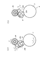
ここで、図1及び図2を参照してスペーサ23について、さらに詳しく説明する。なお、図1(a)と図2(a)は帯電ローラ8と感光体ドラム7が当接した状態を示しており、図1(b)と図2(b)はスペーサ23によって帯電ローラ8が感光体ドラム7から離間した状態を示している。
Here, the
本実施形態のカートリッジBは、出荷時は帯電ローラ8が感光体ドラム7から離間した状態となっており、カートリッジBの最初の使用時に、感光体ドラム7の回転と連動してスペーサ23が回転し、離間状態が解除される構成となっている。
In the cartridge B of this embodiment, the charging
スペーサ23はカム部23aに部分ギアで構成されたスペーサギア23bと、感光体ドラム7と当接する円弧部23cが設けられている。そして、スペーサギア23bから回転力を受けてカム部23aが回転し、図2(b)に示すように、円弧部23cが感光体ドラム7と当接すると帯電ローラ8が感光体ドラム7から約1.5mm離れるようになっている。
The
上記スペーサ23は感光体ドラム7の回転によって回転する。例えば、未使用のカートリッジBは前述のようにスペーサ23の円弧部23cが感光体ドラム7に当接して帯電ローラ8が感光体ドラム7から離間している。このカートリッジBの使用の際は、感光体ドラム7が図1(a)の矢印k方向に正回転(画像形成時の回転方向と同じ方向)する。
The
そして、感光体ドラム7の長手方向一方端部に取り付けられたドラムギア7aから駆動力を受けて、ドラムギア7aと噛合したアイドラギア26が矢印m方向に回転する。これにより、アイドラギア26と噛合した駆動力受け部材としての受けギア25が矢印n方向に回転する。この受けギア25はスペーサ23を前記離間位置から前記当接位置へ移動させるために、感光体ドラム7が回転することにより生ずる駆動力を受けるものである。
Then, upon receiving a driving force from a
そして、前記受けギア25から駆動力を受けて、その駆動力をスペーサ23に伝達する駆動力伝達部材としての伝達ギア24が矢印p方向に回転する。そして、この伝達ギア24と噛合したスペーサギア23bが図2(b)の矢印yの方向に回転する。これによって、帯電ローラ8と感光体ドラム7の離間状態が解除される。
Then, the
このとき、スペーサギア23bと伝達ギア24は途中で噛み合いが外れるようになっており、その後はスペーサ23の自重によって矢印y方向に回転するようにスペーサ23の重心が設定されている。そして、スペーサ23が回転して帯電ローラ8が感光体ドラム7と当接したときは、スペーサ23は前記ギア列と係合せず、感光体ドラム7が回転してもスペーサ23に回転力は伝達されない。
At this time, the
上記のように、スペーサギア23bはドラムギア7aからアイドラギア26、受けギア25、伝達ギア24を介して回転駆動力が伝達される。そして、各ギア26,25,24はドラムユニット20の枠体であるドラム枠体18(図13参照)に取り付けられている。
As described above, the rotational drive force is transmitted to the
なお、スペーサ23は2個のカム部23aが連結部23eによって連結されているために、一方側のカム部23aに回転駆動力を与えるだけ帯電ローラの離間を解除することができる。
In addition, since the
(スペーサへの駆動伝達の遊びとカートリッジ生産工程及び再生産工程)
本実施形態のカートリッジBは前記受けギア25と伝達ギア24の係合部に、一定角度だけ互いに自由に回転できるように遊びが設けられている。この遊びにより、スペーサ23を回転させて帯電ローラ8を感光体ドラム7から離間させる組み立て工程において、感光体ドラム7に負荷がかからないようになっている。次にその構成について説明する。
(Play of drive transmission to spacer, cartridge production process and re-production process)
In the cartridge B of this embodiment, play is provided in the engaging portion of the receiving
図1及び図3に示すように、伝達ギア24と受けギア25は同軸上に設けられており、伝達ギア24に設けられたカップリング部(突起)24aと、受けギア25に設けられたカップリング部(突起)25aが係合することで回転駆動力が伝達されるようになっている。すなわち、受けギア25と伝達ギア24の係合部はカップリング結合部で構成されている。
As shown in FIGS. 1 and 3, the
本実施形態のカップリング部24a,25aの連結部は回転方向に一定角度(本実施形態では約90°)の遊びをもった形状となっており、この範囲は駆動力が伝達されず、互いに自由に回転することができるようになっている。本実施形態では、これらのギア24,25,26がスペーサ23の移動手段を構成している。また、図3に示すように、受けギア25の回転中心には伝達ギア24の軸部24bを貫通させるための貫通穴25bが設けられている。
The coupling part 24a, 25a of the present embodiment has a shape having a play of a certain angle in the rotation direction (about 90 ° in the present embodiment), and in this range no driving force is transmitted, It can be freely rotated. In the present embodiment, these
なお、カートリッジBを組み立てる際の検査工程において、カートリッジBを動作させる、すなわち、感光体ドラム7を画像形成時と同様に回転させることがある。本実施形態の構成では、スペーサ23によって帯電ローラ8と感光体ドラム7とを離間させた後で上記検査工程を行うと、感光体ドラム7の回転によって帯電ローラ8の離間状態が解除され感光体ドラム7に当接してしまう。このため、検査工程の後に帯電ローラ8を感光体ドラム7から離間する必要がある。
In the inspection process when assembling the cartridge B, the cartridge B may be operated, that is, the
帯電ローラ8を感光体ドラム7から離間させるときは、スペーサ23を図2(a)の状態から矢印xの方向に回転させて図2(b)の状態にする。このとき、スペーサギア23bと伝達ギア24が噛み合うため伝達ギア24が回転する。しかし、このときに伝達ギア24が回転する角度(本実施形態では約60°)よりも、伝達ギア24と受けギア25の間の駆動力が伝達されない遊びとなる一定角度(本実施形態では約90°)を大きく設定することで、受けギア25が回転しないようにできる。
When the charging
すなわち、スペーサ23を矢印xの方向に回転させるときは、あらかじめ伝達ギア24を矢印pの方向に回転させ、伝達ギア24のカップリング部24aが受けギア25のカップリング部25aに当接する位置(図1(a)の状態)にしておく。これにより、帯電ローラ8を離間する際に、スペーサ23を図2(a)の矢印x方向に回転し、スペーサギア23bが伝達ギア24と噛合して該伝達ギア24が矢印pと逆方向に回転しても、カップリング部24a,25aは係合しないので伝達ギア24から受けギア25に駆動力が伝達されない。このため、感光体ドラム7を逆回転(矢印rの方向、すなわち画像形成時の回転方向と反対の方向)させる駆動力が生じない。
That is, when the
以上のように、帯電ローラ8を離間させる工程は、まず、感光体ドラム7を画像を形成する際に回転する方向と同方向に回転させて検査する(感光体回転工程)。次に伝達ギア24を画像形成する際に回転する方向と同方向に回転させてカップリング部24aを受けギア25のカップリング部25aに当接させる(伝達ギア回転工程)。この状態にした後、スペーサ23を図2(a)の位置から(b)の位置へ移動させて帯電ローラ8を感光体ドラム7から離間させる(スペーサ移動工程)。
As described above, in the step of separating the charging
これにより、帯電ローラ8を感光体ドラム7から離間させるためにスペーサ23を回転させても感光体ドラム7は回転することがない(この際、帯電ローラ8も回転することがない)。したがって、スペーサ23を小さな負荷で容易に回転させることができる。また、当接離間の際に感光体ドラム7と帯電ローラ8とが摺擦することによるメモリの発生を防止できる。
Thus, even if the
尚、カートリッジBを使用した後にカートリッジBを再生産する場合においては、先ず、電子写真感光体を一端取り外した後にこの電子写真感光体とは異なる他の電子写真感光体を取り付ける(感光体交換工程)。その後、前述した感光体回転工程、伝達ギア回転工程、スペーサ移動工程が用いられる。 In the case of remanufacturing the cartridge B after using the cartridge B, first, the electrophotographic photosensitive member is removed and then another electrophotographic photosensitive member different from the electrophotographic photosensitive member is attached (photosensitive member replacement step). ). Thereafter, the above-described photosensitive member rotation step, transmission gear rotation step, and spacer movement step are used.
また、本実施形態のように、クリーニングブレード17bを感光体ドラム7に当接させる構成では、感光体ドラム7とクリーニングブレード17bの間に潤滑剤が塗布される場合が多い。その場合、帯電ローラ8を離間するときに感光体ドラム7を逆回転すると潤滑剤が剥がれてしまい、その性能を十分に発揮できなくなるおそれがある。しかし、本実施形態の構成にあっては前述のように感光体ドラム7が逆回転することがないので、潤滑剤の効果が損なわれることを抑制することができる。
Further, in the configuration in which the
なお、本実施形態では、図4に示すように、ドラム枠体18の上面に穴18aを設け、スペーサ23には操作部23dを設けている。これにより、穴18aから工具27を挿入し、スペーサ23の操作部23d(図1も参照)に突き当てて矢印uの方向に押せる。このため、組み立て後でも容易にスペーサ23を回転させることができ、帯電ローラ8を感光体ドラム7から離間した状態にすることができる。
In the present embodiment, as shown in FIG. 4, a hole 18 a is provided on the upper surface of the
また、図5に示すように、本実施形態ではカートリッジB(ドラム枠体18)の外部から伝達ギア24を回転させることができるようになっている。すなわち、ドラム枠体18に穴部18bを設け、軸部24bの先端に被係止部としての十字型の溝を構成して、その先端を穴部18bから露出させている。これにより、伝達ギア24をカートリッジBの外部からドライバー等の治具を使って回転させることができる。
また、前記十字型の溝を利用して、係止部としての十字型の突起を有する係止部材(不図示)をドラム枠体18に取り付けることにより、伝達ギア24の回転を規制することもできる。即ち、前記十字型の突起を前記十字型の溝に係合して、前記係止部材を前記ドラム枠体18の表面に設けられたスリット(不図示)にスライドして差し込む。又は、前記十字型の突起を前記十字型の溝に係合して、前記係止部材を前記ドラム枠体18の表面に両面テープ等で貼り付けて固定する。これにより、カートリッジBに衝撃が加わった場合の伝達ギア24の回転をより確実に防止できる。また、前記トナーシールに前記係止部材を取り付けても良い。この場合、操作者が前記トナーシールを引くことにより、伝達ギア24の回転規制も解除することができる。
Further, as shown in FIG. 5, in this embodiment, the
In addition, the rotation of the
(スペーサの逆回転防止)
上記のように本実施形態のカートリッジBは物流搬送時には帯電ローラ8を感光体ドラム7から離間させる。このとき、本実施形態では振動等によりスペーサ23が回転してしまわないようにしている。次にそのための構成について説明する。
(Prevents reverse rotation of spacer)
As described above, the cartridge B of the present embodiment separates the charging
カートリッジBの組み立ての際には、帯電ローラ8とスペーサ23を図2(b)の位相にして矢印wの方向から感光体ドラム7をドラム枠体18に組み付ける。感光体ドラム7が最初にスペーサ23の円弧部23cに当接し、スペーサ23が持ち上げられることにより帯電ローラ8が感光体ドラム7から離間される。また、このとき伝達ギア24とスペーサギア23bが噛み合う。
When assembling the cartridge B, the
このようにして組み立てられたカートリッジBは図2(b)の状態で出荷される。そして、その物流搬送の際にはカートリッジBは様々な振動や衝撃を受けることになる。このとき、感光体ドラム7に当接するクリーニングブレード17aは、感光体ドラム7にその先端部が食い込むようにカウンターで当接している(図10参照)。このようなクリーニングブレード17aの当接により、感光体ドラム7を正回転(図10の矢印k方向)させるのに必要な力は大きく、逆回転(矢印kと反対の向き)させるのに必要な力は小さくなる。よって、物流時、振動等によって感光体ドラム7が逆回転(矢印kと反対の向き)しやすい。本実施形態では、スペーサ23の逆回転(矢印y方向と逆方向)を規制することで、感光体ドラム7の逆回転を防止している。
The cartridge B assembled in this way is shipped in the state shown in FIG. The cartridge B is subjected to various vibrations and shocks during the physical distribution. At this time, the cleaning blade 17a that is in contact with the
本実施形態では、スペーサ23の感光体ドラム7との当接部の円弧部23c形状を図6のような形状としている。
In the present embodiment, the shape of the
なお、本実施形態では感光体ドラム7の直径を30mm、帯電ローラ8のローラ直径を12mm、ローラ軸部8aの直径を6mm、感光体ドラム7と帯電ローラ8との離間距離を1.5mm、円弧部23cの直径を感光体ドラム7と同じ30mmとしている。
In this embodiment, the diameter of the
そして、円弧部23cは帯電ローラ8の回転軸中心と感光体ドラム7の回転軸中心とを結んだ中心線Lを挟んで非対称形状にしている。このため、感光体ドラム7の正回転(矢印k方向の回転)側のポイントV1と中心線Lとの距離をT1、逆回転側のポイントV2と中心線Lとの距離をT2とするとT1<T2となるように設定する。本実施形態ではT1=1.1mm、T2=3.3mmとした。
The
前記距離T1及びT2は小さいほどスペーサ23が回転するのに必要な回転力が小さくなり、逆に大きくするほどスペーサ23が回転するのに必要な回転力が大きくなる。なぜならスペーサ23が回転するとき、ポイントV1またはV2がスペーサ23自身の回転の支点となって、バネ22で付勢されている帯電ローラ金属軸部8aを持ち上げなければならない。そして、回転半径R1、R2の違いにより、持ち上げストローク量が大きいほうがバネ22を圧縮させる量が大きくなり、反発力が大きくなるからである。
The smaller the distances T1 and T2, the smaller the rotational force necessary for the
前述のように物流時等にあって感光体ドラム7はクリーニングブレード17aの当接により正回転(矢印k方向)しないが、物流の衝撃などによって、スペーサ23自身が矢印y方向に回転する可能性はある。このため、その程度の衝撃ではスペーサ23が回転しないよう、また、画像形成開始の際の本体駆動時にはスペーサ23が回転できるようにT1の距離を設定する。これはカートリッジBの全体重量や梱包状態などによって、適宜決められるものであり、前述の値に限ったものではない。
As described above, the
本実施形態の場合は、感光体ドラム7の正回転の場合、帯電ローラ8の金属軸8aを離間状態からさらに0.3mm程度持ち上げるようストローク量を設定した(図7参照)。この程度であれば本体駆動によって離間が確実に解除できる。一方、前記距離T2はT1よりも大きく設定しているため、物流時の振動等で感光体ドラム7が逆転しようとした場合でも、金属軸8aの持ち上げストローク量は1mmと大きく、少ない力では持ち上げることができない。このため、スペーサ23の逆回転(図7の矢印y方向と逆方向)の動きが規制され、感光体ドラム7の逆回転を防止することができる。
In this embodiment, when the
なお、前記構成のみならず、図8に示すように、スペーサ23が正回転(矢印y方向)するときには当接しないが、逆回転しようとするとスペーサ23と当接する規制部17cを設けることで、スペーサ23の動きを規制するようにしてもよい。
In addition to the above-described configuration, as shown in FIG. 8, by providing a restricting
また、帯電ローラ8の金属軸8aを持ち上げることができる空間を、スペーサ23が正回転するときに必要な量よりは大きく、逆回転するときに必要な量よりは小さくするようにしてもよい。このようにすることで、金属軸8aや軸受21が移動したときに、それらの支持枠体に干渉するようにすれば、スペーサ23が逆転できない。これによって感光体ドラム7の逆回転を防止することが可能となる。
Further, the space in which the metal shaft 8a of the charging
〔他の実施形態〕
次に前述したスペーサ23への駆動伝達の他の実施形態について図面を用いて説明する。なお、本実施形態の装置の基本構成は前述した実施形態と同一であるため重複する説明は省略し、ここでは第1実施形態と異なる構成のみについて説明する。また、前述した実施形態と同一機能を有する部材には同一符号を付す。
[Other Embodiments]
Next, another embodiment of drive transmission to the
図14はスペーサ23へ駆動力を伝達するギア列の途中にカップリング部を設けた実施形態を示すものである。この実施形態では感光体ドラム7のドラムギア7aからギア28,29,30,31と駆動を伝達し、スペーサ23を動かす構成となっている。そして、駆動伝達の途中のギア28とギア29に前述した第1実施形態と同様に、互いに自由に回転することができる範囲をもつようにカップリング部28a,29aが形成されている。このようにギア列の途中にカップリング部を設けた構成でも第1実施形態と同様の効果を得ることができる。
FIG. 14 shows an embodiment in which a coupling portion is provided in the middle of a gear train that transmits a driving force to the
図15はスペーサ23への駆動伝達にベルトを用いた実施形態を示すものである。前述した第1実施形態では感光体ドラム7からスペーサ23への駆動伝達にギアを用いていた。これに対して本実施形態では、図15に示すように、感光体ドラム7からプーリ32への駆動伝達にベルト33を使用している。そして、このプーリ32とスペーサ23に駆動力を伝達するギア33の間に第1実施形態と同様に、互いに自由に回転することができる範囲をもつようにカップリング部を設けている。このような構成でも第1実施形態と同様の効果を得ることができる。
FIG. 15 shows an embodiment in which a belt is used for drive transmission to the
A …装置本体
B …カートリッジ
7 …感光体ドラム
7a …ドラムギア
8 …帯電ローラ
8a …金属軸
17 …クリーニング手段
17a …クリーニングブレード
18 …ドラム枠体
18a …穴
18b …穴部
19 …現像ユニット
20 …ドラムユニット
21 …軸受
22 …加圧バネ
23 …スペーサ
23a …カム部
23b …スペーサギア
23c …円弧部
23d …操作部
23e …連結部
24 …伝達ギア
24a,25a …カップリング部
24b …軸部
25 …受けギア
25b …貫通穴
26 …アイドラギア
27 …工具
28,29,30,31 …ギア
28a,29a …カップリング部
32 …プーリ
33 …ベルト
A ... Device body B ...
17 Cleaning means
17a ... Cleaning blade
18 Drum frame
18a ... hole
18b ... hole
19… Development unit
20… Drum unit
21… Bearing
22… Pressure spring
23… Spacer
23a ... Cam part
23b ... Spacer gear
23c ... Circular arc part
23d Operation unit
23e ... Connection part
24… Transmission gear
24a, 25a ... Coupling part
24b ... Shaft
25… receiving gear
25b… through hole
26… idler gear
27… Tool
28, 29, 30, 31 ... Gear
28a, 29a ... Coupling part
32… pulley
33… Belt
Claims (11)
回転可能な電子写真感光体と、
前記電子写真感光体と当接して前記電子写真感光体を帯電するための帯電ローラと、
前記電子写真感光体と前記帯電ローラとを離間させるための離間部材であって、前記電子写真感光体と前記帯電ローラとを離間させる離間位置と、前記電子写真感光体と前記帯電ローラとを当接させる当接位置と、の間を移動可能な離間部材と、
前記電子写真感光体が回転することにより生ずる駆動力を受ける回転可能な駆動力受け部材と、
前記離間部材を前記離間位置から前記当接位置へ移動させるために、前記駆動力受け部材と係合して前記駆動力を前記駆動力受け部材から前記離間部材に伝達する回転可能な駆動力伝達部材と、
を有し、
前記駆動力受け部材と前記駆動力伝達部材の係合部に、離間部材を当接位置から離間位置に移動させた際に、前記駆動力受け部が回転しないように一定角度だけ互いに自由に回転できるように遊びが設けられていることを特徴とするプロセスカートリッジ。 A process cartridge that is detachable from an apparatus main body of an electrophotographic image forming apparatus for forming an image on a recording medium,
A rotatable electrophotographic photoreceptor;
A charging roller for contacting the electrophotographic photosensitive member to charge the electrophotographic photosensitive member;
A separation member for separating the electrophotographic photosensitive member from the charging roller, wherein a separation position for separating the electrophotographic photosensitive member from the charging roller, and the electrophotographic photosensitive member to the charging roller A contact position to be contacted, and a separation member movable between,
A rotatable driving force receiving member for receiving a driving force generated by rotation of the electrophotographic photosensitive member;
A rotatable driving force transmission that engages with the driving force receiving member and transmits the driving force from the driving force receiving member to the separating member to move the separating member from the separating position to the contact position. A member,
Have
When the separation member is moved from the contact position to the separation position in the engagement portion between the driving force receiving member and the driving force transmission member , the driving force receiving portion freely rotates by a certain angle so as not to rotate. A process cartridge provided with play so as to be able to do so.
回転可能な電子写真感光体と、
前記電子写真感光体と当接して前記電子写真感光体を帯電するための帯電ローラと、
前記電子写真感光体と前記帯電ローラとを離間させるための離間部材であって、前記電子写真感光体と前記帯電ローラとを離間させる離間位置と、前記電子写真感光体と前記帯電ローラとを当接させる当接位置と、の間を移動可能な離間部材と、
前記離間部材を前記離間位置から前記当接位置へ移動させるために、画像を形成する際に回転する方向と同方向に前記電子写真感光体が回転することにより生ずる駆動力を受ける回転可能な駆動力受け部材と、
前記離間部材を前記離間位置から前記当接位置へ移動させるために、前記駆動力受け部材と係合して、前記駆動力を前記駆動力受け部材から前記離間部材に伝達する回転可能な駆動力伝達部材と、
を有し、
前記駆動力受け部材と前記駆動力伝達部材とが係合している係合部に、離間部材を当接位置から離間位置に移動させた際に、前記駆動力受け部が回転しないように前記駆動力受け部材と前記駆動力伝達部材とが互いに一定角度だけ自由に回転できるように遊びが設けられており、前記電子写真感光体が画像を形成する際に回転する方向と同方向に前記電子写真感光体を回転させた後に、前記駆動力伝達部材が画像を形成する際に回転する方向と同方向に前記駆動力伝達部材を回転させて、その後に前記離間部材を前記当接位置から前記離間位置へ移動させたことを特徴とするプロセスカートリッジ。 A process cartridge that is detachable from an apparatus main body of an electrophotographic image forming apparatus for forming an image on a recording medium,
A rotatable electrophotographic photoreceptor;
A charging roller for contacting the electrophotographic photosensitive member to charge the electrophotographic photosensitive member;
A separation member for separating the electrophotographic photosensitive member from the charging roller, wherein a separation position for separating the electrophotographic photosensitive member from the charging roller, and the electrophotographic photosensitive member to the charging roller A contact position to be contacted, and a separation member movable between,
In order to move the separation member from the separation position to the contact position, a rotatable drive that receives a driving force generated by the rotation of the electrophotographic photosensitive member in the same direction as the rotation direction when forming an image. A force receiving member;
A rotatable driving force that engages with the driving force receiving member and transmits the driving force from the driving force receiving member to the separating member to move the separating member from the separating position to the contact position. A transmission member;
Have
The driving force receiving portion is prevented from rotating when the separating member is moved from the contact position to the separating position in the engaging portion where the driving force receiving member and the driving force transmitting member are engaged. A play is provided so that the driving force receiving member and the driving force transmission member can freely rotate with respect to each other by a predetermined angle, and the electrophotographic photosensitive member rotates in the same direction as the rotation direction when forming an image. After rotating the photoconductor, the driving force transmitting member is rotated in the same direction as the driving force transmitting member rotates when forming an image, and then the separating member is moved from the contact position to the contact position. A process cartridge which is moved to a separated position.
前記装置本体と、
を有する電子写真画像形成装置。 A process cartridge according to any one of claims 1 to 8,
The device body;
An electrophotographic image forming apparatus.
前記電子写真感光体が画像を形成する際に回転する方向と同方向に前記電子写真感光体を回転させる感光体回転工程と、
前記感光体回転工程の後に、前記駆動力伝達部材が画像を形成する際に回転する方向と同方向に前記駆動力伝達部材を回転させる伝達部材回転工程と、
前記伝達部材回転工程の後に、前記離間部材を前記当接位置から前記離間位置へ移動させる第3工程と、
を有することを特徴とするプロセスカートリッジの生産方法。 A process cartridge that can be attached to and detached from an apparatus main body of an electrophotographic image forming apparatus for forming an image on a recording medium, the electrophotographic photosensitive member being rotatable, and a charging roller for charging the electrophotographic photosensitive member, A separation member movable between a separation position for separating the electrophotographic photosensitive member and the charging roller and a contact position for contacting the electrophotographic photosensitive member and the charging roller, and an image is formed. A driving force receiving member that receives a driving force generated by rotating the electrophotographic photosensitive member in the same direction as the rotating direction, and a driving force receiving member that engages with the driving force receiving member to drive the driving force. A rotatable driving force transmission member that transmits the force receiving member to the separation member , and the separation member is brought into contact with an engaging portion where the driving force reception member and the driving force transmission member are engaged with each other. Away from When obtained by the dynamic method for producing a process cartridge in which the driving force receiving portion and said driving force receiving member so as not to rotate with the driving force transmitting member is play is provided so as to be free to rotate by a predetermined angle to each other In
A photosensitive member rotating step of rotating the electrophotographic photosensitive member in the same direction as the rotating direction when the electrophotographic photosensitive member forms an image;
A transmission member rotation step of rotating the driving force transmission member in the same direction as the direction in which the driving force transmission member rotates when the image is formed after the photosensitive member rotation step;
A third step of moving the separation member from the contact position to the separation position after the transmission member rotation step;
A process cartridge production method characterized by comprising:
前記電子写真感光体を取り外した後に、前記電子写真感光体とは異なる他の電子写真感光体を取り付ける感光体交換工程と、
前記感光体交換工程の後に、前記他の電子写真感光体が画像を形成する際に回転する方向と同方向に前記他の電子写真感光体を回転させる感光体回転工程と、
前記感光体回転工程の後に、前記駆動力伝達部材が画像を形成する際に回転する方向と同方向に前記駆動力伝達部材を回転させる伝達部材回転工程と、
前記伝達部材回転工程の後に、前記離間部材を前記当接位置から前記離間位置へ移動させる離間部材移動工程と、
を有することを特徴とするプロセスカートリッジの再生産方法。 A process cartridge that can be attached to and detached from an apparatus main body of an electrophotographic image forming apparatus for forming an image on a recording medium, the electrophotographic photosensitive member being rotatable, and a charging roller for charging the electrophotographic photosensitive member, A separation member movable between a separation position for separating the electrophotographic photosensitive member and the charging roller and a contact position for contacting the electrophotographic photosensitive member and the charging roller, and an image is formed. A driving force receiving member that receives a driving force generated by rotating the electrophotographic photosensitive member in the same direction as the rotating direction, and a driving force receiving member that engages with the driving force receiving member to drive the driving force. A rotatable driving force transmission member that transmits the force receiving member to the separation member , and the separation member is brought into contact with an engaging portion where the driving force reception member and the driving force transmission member are engaged with each other. Away from When obtained by the dynamic, remanufacturing of the process cartridge in which the driving force receiving portion and said driving force receiving member so as not to rotate with the driving force transmitting member is play is provided so as to be free to rotate by a predetermined angle to each other In the method
After removing the electrophotographic photoconductor, a photoconductor replacement step of attaching another electrophotographic photoconductor different from the electrophotographic photoconductor,
After the photoconductor replacement step, a photoconductor rotation step for rotating the other electrophotographic photoconductor in the same direction as the direction in which the other electrophotographic photoconductor rotates when forming an image,
A transmission member rotation step of rotating the driving force transmission member in the same direction as the direction in which the driving force transmission member rotates when the image is formed after the photosensitive member rotation step;
A separation member moving step of moving the separation member from the contact position to the separation position after the transmission member rotation step;
A process cartridge remanufacturing method comprising:
Priority Applications (2)
| Application Number | Priority Date | Filing Date | Title |
|---|---|---|---|
| JP2006115169A JP4804212B2 (en) | 2006-04-19 | 2006-04-19 | Process cartridge, electrophotographic image forming apparatus, process cartridge production method and reproduction method |
| US11/613,521 US7865115B2 (en) | 2006-04-19 | 2006-12-20 | Process cartridge, electrophotographic image forming apparatus, method of manufacturing a process cartridge, and method of remanufacturing a process cartridge |
Applications Claiming Priority (1)
| Application Number | Priority Date | Filing Date | Title |
|---|---|---|---|
| JP2006115169A JP4804212B2 (en) | 2006-04-19 | 2006-04-19 | Process cartridge, electrophotographic image forming apparatus, process cartridge production method and reproduction method |
Publications (3)
| Publication Number | Publication Date |
|---|---|
| JP2007286455A JP2007286455A (en) | 2007-11-01 |
| JP2007286455A5 JP2007286455A5 (en) | 2010-07-08 |
| JP4804212B2 true JP4804212B2 (en) | 2011-11-02 |
Family
ID=38619585
Family Applications (1)
| Application Number | Title | Priority Date | Filing Date |
|---|---|---|---|
| JP2006115169A Expired - Fee Related JP4804212B2 (en) | 2006-04-19 | 2006-04-19 | Process cartridge, electrophotographic image forming apparatus, process cartridge production method and reproduction method |
Country Status (2)
| Country | Link |
|---|---|
| US (1) | US7865115B2 (en) |
| JP (1) | JP4804212B2 (en) |
Families Citing this family (32)
| Publication number | Priority date | Publication date | Assignee | Title |
|---|---|---|---|---|
| JP2010072623A (en) * | 2008-08-19 | 2010-04-02 | Canon Inc | Image forming apparatus |
| JP5506236B2 (en) | 2009-04-30 | 2014-05-28 | キヤノン株式会社 | Cartridge and electrophotographic image forming apparatus |
| KR101698392B1 (en) * | 2009-09-18 | 2017-01-26 | 삼성전자주식회사 | Developing unit and image forming apparatus using the same |
| US8942592B2 (en) | 2009-12-16 | 2015-01-27 | Canon Kabushiki Kaisha | Process cartridge, photosensitive drum unit, developing unit and electrophotographic image forming apparatus |
| JP5653097B2 (en) * | 2010-07-07 | 2015-01-14 | キヤノン株式会社 | Image forming unit |
| JP2012082846A (en) * | 2010-10-06 | 2012-04-26 | Ricoh Co Ltd | Gear drive mechanism, driving device with the same, and image forming apparatus with the same |
| JP5817254B2 (en) * | 2011-06-29 | 2015-11-18 | ブラザー工業株式会社 | Image forming apparatus |
| JP5812751B2 (en) * | 2011-08-05 | 2015-11-17 | キヤノン株式会社 | Process cartridge |
| EP2776890B1 (en) | 2011-11-09 | 2020-01-08 | Canon Kabushiki Kaisha | Cartridge and unit, seal member and blade member |
| JP5460824B2 (en) | 2011-12-09 | 2014-04-02 | キヤノン株式会社 | cartridge |
| WO2013099999A2 (en) | 2011-12-26 | 2013-07-04 | Canon Kabushiki Kaisha | Developing device, process cartridge and drum unit |
| JP5355679B2 (en) | 2011-12-27 | 2013-11-27 | キヤノン株式会社 | Process cartridge and image forming apparatus |
| JP5893414B2 (en) * | 2012-01-17 | 2016-03-23 | キヤノン株式会社 | Process cartridge and image forming apparatus |
| JP6218493B2 (en) | 2012-09-06 | 2017-10-25 | キヤノン株式会社 | Unit, unit manufacturing method, image forming apparatus, and image forming apparatus manufacturing method |
| JP2014071428A (en) | 2012-10-01 | 2014-04-21 | Canon Inc | Process cartridge |
| JP2016017551A (en) * | 2014-07-07 | 2016-02-01 | 株式会社リコー | Driving power transmission deice, process unit and image formation device |
| US9535398B2 (en) | 2014-09-04 | 2017-01-03 | Canon Kabushiki Kaisha | Developer cartridge, developing apparatus, process cartridge and image forming apparatus |
| JP6465667B2 (en) * | 2015-01-22 | 2019-02-06 | キヤノン株式会社 | Photoconductor unit |
| KR102000331B1 (en) * | 2015-01-22 | 2019-07-15 | 캐논 가부시끼가이샤 | Photosensitive member unit and image forming apparatus including the same |
| JP6486145B2 (en) * | 2015-02-27 | 2019-03-20 | キヤノン株式会社 | Cartridge and image forming apparatus |
| KR102128342B1 (en) | 2016-07-04 | 2020-07-08 | 캐논 가부시끼가이샤 | Reproduction method for developing device |
| JP6827732B2 (en) * | 2016-07-22 | 2021-02-10 | キヤノン株式会社 | Image forming device |
| KR20180054024A (en) * | 2016-11-14 | 2018-05-24 | 에이치피프린팅코리아 주식회사 | development cartridge and electrophotographic image forming apparatus adapting the same |
| US10444701B2 (en) * | 2017-02-14 | 2019-10-15 | Canon Kabushiki Kaisha | Image forming apparatus |
| FR3065057A1 (en) * | 2017-04-11 | 2018-10-12 | Valeo Vision | LUMINOUS DEVICE WITH ELECTRICAL CONTACT BETWEEN ICE AND HOUSING |
| BR112019026700A2 (en) | 2017-06-15 | 2020-06-23 | Canon Kabushiki Kaisha | ELECTRIC PHOTOGRAPHIC IMAGE TRAINING CARTRIDGE AND APPLIANCE |
| JP7207921B2 (en) | 2018-09-26 | 2023-01-18 | キヤノン株式会社 | photoreceptor unit |
| JP7237562B2 (en) * | 2018-12-19 | 2023-03-13 | キヤノン株式会社 | photoreceptor unit |
| US10969730B2 (en) | 2019-02-25 | 2021-04-06 | Canon Kabushiki Kaisha | Image forming apparatus and image forming unit |
| CA3125097A1 (en) | 2019-03-18 | 2020-09-24 | Canon Kabushiki Kaisha | Electrophotographic image forming apparatus and cartridge |
| JP7282586B2 (en) * | 2019-04-25 | 2023-05-29 | キヤノン株式会社 | image forming device |
| US11592758B2 (en) * | 2020-11-26 | 2023-02-28 | Canon Kabushiki Kaisha | Photosensitive member unit capable of preventing a photosensitive member and a charging roller from accidentally being released from a separation state |
Family Cites Families (45)
| Publication number | Priority date | Publication date | Assignee | Title |
|---|---|---|---|---|
| JP3279780B2 (en) | 1993-12-02 | 2002-04-30 | 株式会社リコー | Roller positioning device for image forming apparatus |
| US5596395A (en) * | 1994-09-21 | 1997-01-21 | Ricoh Company, Ltd. | Image forming apparatus and its control system having a single device for moving a charging member and a transfer member |
| JP3839932B2 (en) * | 1996-09-26 | 2006-11-01 | キヤノン株式会社 | Process cartridge, electrophotographic image forming apparatus, electrophotographic photosensitive drum and coupling |
| US5768658A (en) | 1995-07-21 | 1998-06-16 | Canon Kabushiki Kaisha | Electrode member, developing apparatus, process cartridge and image forming apparatus |
| US5666608A (en) * | 1996-05-02 | 1997-09-09 | Hewlett-Packard Company | Charging member and image forming member spacer apparatus |
| JP3382465B2 (en) | 1996-07-04 | 2003-03-04 | キヤノン株式会社 | Process cartridge and electrophotographic image forming apparatus |
| JP3337915B2 (en) | 1996-07-04 | 2002-10-28 | キヤノン株式会社 | Process cartridge, method of assembling process cartridge, and image forming apparatus |
| JPH10142969A (en) * | 1996-11-11 | 1998-05-29 | Ricoh Co Ltd | Image forming device |
| JP3524334B2 (en) | 1997-02-10 | 2004-05-10 | キヤノン株式会社 | Developing unit, process cartridge, electrophotographic image forming apparatus, and toner seal |
| JPH1124452A (en) * | 1997-06-30 | 1999-01-29 | Ricoh Co Ltd | Image forming device |
| JPH1195532A (en) * | 1997-09-19 | 1999-04-09 | Ricoh Co Ltd | Electrifier for image forming device |
| JPH11143226A (en) | 1997-11-11 | 1999-05-28 | Canon Inc | Process cartridge and developing device |
| EP1016939B1 (en) | 1998-12-28 | 2006-02-01 | Canon Kabushiki Kaisha | Image developing apparatus, process cartridge, electrophotographic image forming apparatus, and development unit frame |
| JP2000320537A (en) | 1999-05-10 | 2000-11-24 | Minolta Co Ltd | Rotary unit holder device and image forming device using the rotary unit holder device |
| JP2001013762A (en) * | 1999-06-30 | 2001-01-19 | Ricoh Co Ltd | Electrification device |
| JP2001092335A (en) | 1999-09-17 | 2001-04-06 | Canon Inc | Process cartridge, electrophotographic image forming device and developer quantity detection member |
| US6385420B1 (en) * | 1999-10-06 | 2002-05-07 | Canon Kabushiki Kaisha | Charging apparatus for contacting and separating charging member by use of moving force of body to be charged |
| JP2001117467A (en) * | 1999-10-14 | 2001-04-27 | Canon Inc | Process cartridge, image forming device and assembly |
| JP3745231B2 (en) | 2000-01-13 | 2006-02-15 | キヤノン株式会社 | Process cartridge and electrophotographic image forming apparatus |
| JP2001290355A (en) | 2000-04-06 | 2001-10-19 | Canon Inc | Developing device, process cartridge and electrophotographic image forming device |
| JP3720671B2 (en) | 2000-04-06 | 2005-11-30 | キヤノン株式会社 | Developing device, process cartridge, and electrophotographic image forming apparatus |
| JP3283500B2 (en) * | 2000-06-28 | 2002-05-20 | キヤノン株式会社 | Process cartridge remanufacturing method |
| US6587650B2 (en) | 2000-07-28 | 2003-07-01 | Canon Kabushiki Kaisha | Electrophotographic image forming apparatus, process cartridge, and developing device having developer amount detector |
| JP3658289B2 (en) | 2000-07-28 | 2005-06-08 | キヤノン株式会社 | Process cartridge and electrophotographic image forming system |
| JP2002139904A (en) | 2000-10-31 | 2002-05-17 | Canon Inc | Developing device, process cartridge and electrophotographic image forming device |
| JP3423684B2 (en) | 2000-11-28 | 2003-07-07 | キヤノン株式会社 | Developing device, process cartridge, electrophotographic image forming device, and electrical contact member |
| JP2002258720A (en) | 2001-03-05 | 2002-09-11 | Canon Inc | Electrophotographic image forming device and process cartridge |
| JP3697168B2 (en) | 2001-03-09 | 2005-09-21 | キヤノン株式会社 | Process cartridge and electrophotographic image forming apparatus |
| JP2002268513A (en) | 2001-03-09 | 2002-09-20 | Canon Inc | Electrophotographic image forming apparatus and process cartridge |
| JP2002311690A (en) | 2001-04-18 | 2002-10-23 | Canon Inc | Electrifier, process cartridge and image forming device |
| JP2003076117A (en) * | 2001-09-03 | 2003-03-14 | Masamichi Sato | Method of reducing, releasing and resetting pressurizing and touching force of electrostatic charging roller to photosensitive drum and process cartridge |
| JP3969990B2 (en) | 2001-10-10 | 2007-09-05 | キヤノン株式会社 | Developing device, process cartridge, and image forming apparatus |
| JP3548558B2 (en) | 2001-12-13 | 2004-07-28 | キヤノン株式会社 | Process cartridge and electrophotographic image forming apparatus |
| US6922534B2 (en) | 2001-12-28 | 2005-07-26 | Canon Kabushiki Kaisha | Process cartridge and electrophotographic image forming apparatus having electrical connection for memory |
| JP3907496B2 (en) | 2002-02-27 | 2007-04-18 | キヤノン株式会社 | Developing device, process cartridge, electrophotographic image forming apparatus, developer container and method of assembling the same |
| JP3848191B2 (en) | 2002-03-25 | 2006-11-22 | キヤノン株式会社 | Developing device, process cartridge, and electrophotographic image forming apparatus |
| JP4194298B2 (en) | 2002-05-17 | 2008-12-10 | キヤノン株式会社 | Information storage medium, unit, process cartridge, developing cartridge, and electrophotographic image forming apparatus |
| KR100433422B1 (en) | 2002-07-19 | 2004-05-31 | 삼성전자주식회사 | Roller spacing device |
| JP3970161B2 (en) | 2002-11-08 | 2007-09-05 | キヤノン株式会社 | Process cartridge remanufacturing method |
| JP2004163708A (en) | 2002-11-14 | 2004-06-10 | Murata Mach Ltd | Image forming apparatus |
| JP3625470B1 (en) | 2003-09-30 | 2005-03-02 | キヤノン株式会社 | Process cartridge and electrophotographic image forming apparatus |
| JP2005157169A (en) * | 2003-11-28 | 2005-06-16 | Canon Inc | Image forming apparatus and process unit |
| US7477862B2 (en) * | 2004-02-09 | 2009-01-13 | Ricoh Company, Ltd. | Charged device, cleaning device, process cartridge, toner, and image-forming device that uses these |
| JP4095589B2 (en) | 2004-02-27 | 2008-06-04 | キヤノン株式会社 | Electrophotographic image forming apparatus and process cartridge |
| KR100629497B1 (en) * | 2005-09-06 | 2006-09-28 | 삼성전자주식회사 | Apparatus for spacing out rollers and image forming device having the same |
-
2006
- 2006-04-19 JP JP2006115169A patent/JP4804212B2/en not_active Expired - Fee Related
- 2006-12-20 US US11/613,521 patent/US7865115B2/en not_active Expired - Fee Related
Also Published As
| Publication number | Publication date |
|---|---|
| US20070248382A1 (en) | 2007-10-25 |
| US7865115B2 (en) | 2011-01-04 |
| JP2007286455A (en) | 2007-11-01 |
Similar Documents
| Publication | Publication Date | Title |
|---|---|---|
| JP4804212B2 (en) | Process cartridge, electrophotographic image forming apparatus, process cartridge production method and reproduction method | |
| JP4458377B2 (en) | Process cartridge and electrophotographic image forming apparatus | |
| JP5106656B2 (en) | Process cartridge and image forming apparatus | |
| JP3884960B2 (en) | Driving device and color image forming apparatus | |
| US9002234B2 (en) | Image forming unit | |
| KR100788037B1 (en) | Photosensitive drum for printer cartridge and method for mounting the same | |
| US8204400B2 (en) | Charging device capable of efficiently charging image carrier | |
| US9026006B2 (en) | Image forming apparatus | |
| US8995881B2 (en) | Image forming apparatus and image carrier including a backward-rotation-suppressing mechanism | |
| JP2013250342A (en) | Structure, image forming apparatus, and drive transmission mechanism | |
| JP2012088689A (en) | Cartridge and image forming apparatus | |
| CA3194108A1 (en) | Drum unit, cartridge, electrophotographic image forming apparatus, and coupling member | |
| JP2013122537A (en) | Image forming apparatus and drive transmission apparatus | |
| JP2016090793A (en) | Image formation apparatus | |
| JP2014016432A (en) | Drive device and image forming apparatus | |
| JP3937802B2 (en) | Process cartridge | |
| JP2007256353A (en) | Image forming apparatus and developing cartridge | |
| JP2006337725A (en) | Process cartridge and electrophotographic image forming apparatus | |
| JP5866885B2 (en) | Photosensitive unit and image forming apparatus | |
| JP5683221B2 (en) | Support and fixing structure for process means, image forming apparatus having the same, process cartridge, and developing apparatus | |
| JP2007298666A (en) | Apparatus having drive unit and driven unit | |
| JP2013213549A (en) | Driving force transmission device, driving device and imaging device | |
| JP2007047298A (en) | Phase matching assembly method for separation member used for process cartridge | |
| JP5471802B2 (en) | Connecting mechanism and image forming apparatus | |
| JP2009012947A (en) | Paper tray attachment/detachment mechanism and image forming device |
Legal Events
| Date | Code | Title | Description |
|---|---|---|---|
| RD02 | Notification of acceptance of power of attorney |
Free format text: JAPANESE INTERMEDIATE CODE: A7422 Effective date: 20080116 |
|
| A621 | Written request for application examination |
Free format text: JAPANESE INTERMEDIATE CODE: A621 Effective date: 20090416 |
|
| A521 | Request for written amendment filed |
Free format text: JAPANESE INTERMEDIATE CODE: A523 Effective date: 20100524 |
|
| A977 | Report on retrieval |
Free format text: JAPANESE INTERMEDIATE CODE: A971007 Effective date: 20110729 |
|
| TRDD | Decision of grant or rejection written | ||
| A01 | Written decision to grant a patent or to grant a registration (utility model) |
Free format text: JAPANESE INTERMEDIATE CODE: A01 Effective date: 20110802 |
|
| A01 | Written decision to grant a patent or to grant a registration (utility model) |
Free format text: JAPANESE INTERMEDIATE CODE: A01 |
|
| A61 | First payment of annual fees (during grant procedure) |
Free format text: JAPANESE INTERMEDIATE CODE: A61 Effective date: 20110809 |
|
| R151 | Written notification of patent or utility model registration |
Ref document number: 4804212 Country of ref document: JP Free format text: JAPANESE INTERMEDIATE CODE: R151 |
|
| FPAY | Renewal fee payment (event date is renewal date of database) |
Free format text: PAYMENT UNTIL: 20140819 Year of fee payment: 3 |
|
| LAPS | Cancellation because of no payment of annual fees |