JP3937802B2 - Process cartridge - Google Patents
Process cartridge Download PDFInfo
- Publication number
- JP3937802B2 JP3937802B2 JP2001331832A JP2001331832A JP3937802B2 JP 3937802 B2 JP3937802 B2 JP 3937802B2 JP 2001331832 A JP2001331832 A JP 2001331832A JP 2001331832 A JP2001331832 A JP 2001331832A JP 3937802 B2 JP3937802 B2 JP 3937802B2
- Authority
- JP
- Japan
- Prior art keywords
- driving force
- frame
- developer
- force transmission
- transmission member
- Prior art date
- Legal status (The legal status is an assumption and is not a legal conclusion. Google has not performed a legal analysis and makes no representation as to the accuracy of the status listed.)
- Expired - Lifetime
Links
Images


Description
【0001】
【発明の属する技術分野】
本発明は、プロセスカートリッジおよびプロセスカートリッジを用いる電子写真画像形成装置に関するものである。
【0002】
ここで、電子写真画像形成装置としては、例えば電子写真複写機、電子写真プリンター(例えば、LEDプリンター、レーザービームプリンター等)、電子写真ファクシミリ装置、および電子写真ワードプロセッサー等が含まれる。
【0003】
また、プロセスカートリッジとしては、少なくとも現像手段(現像剤担持体)と電子写真感光体を一体的にカートリッジ化して画像形成装置本体に着脱可能とするものをいう。
【0004】
【従来の技術】
従来、電子写真画像形成プロセスを用いた電子写真画像形成装置においては、電子写真感光体ドラムおよび該電子写真感光体ドラムに作用するプロセス手段を一体的にカートリッジ化して、このカートリッジを電子写真画像形成装置本体に対して着脱可能とするプロセスカートリッジ方式が採用されている。
【0005】
この種のプロセスカートリッジ方式によれば、装置のメンテナンスをサービスマンによらずにユーザー自身で行うことができるので、格段に操作性を向上させることができる。そこで、このプロセスカートリッジ方式は、電子写真画像形成装置において広く用いられている。
【0006】
この種の従来のプロセスカートリッジは、例えば、感光体ユニットと現像装置ユニットから構成されている。感光体ユニットには、静電潜像を形成する電子写真感光体ドラム(以下、単に感光体ドラムともいう)、感光層表面を一様に帯電させるための帯電手段である帯電ローラ、および記録媒体に転写されずに感光体ドラムに付着している残留現像剤を感光体ドラム表面からかき落とし、除去現像剤容器に貯蔵するためのクリーニング手段が配置されている。
【0007】
また、現像装置ユニットには、現像剤を収容する現像剤収納容器、感光体ドラムに形成された静電潜像に現像剤を供給して可視画像を形成させるための現像剤担持体である現像ローラ、現像剤に摩擦帯電電荷を付与し、現像ローラの表面上に現像剤層を形成する現像ブレード、および現像ローラの半径方向の現像剤漏洩を防止する吹出し防止シート等が配置されている。そして、現像ローラや現像ブレードは現像器枠体に保持され、この現像器枠体を現像剤収納容器に結合して現像装置ユニットを構成している。
【0008】
これらの現像装置ユニットと感光体ユニットは、係合ピンで回動可能に結合され、現像装置ユニットと感光体ユニットとの間には付勢バネが設けられている。
【0009】
また、感光体ドラムの端部に設けられたドラムギアは、画像形成装置に配置された駆動ギアを介して駆動力が伝達され、感光体ドラムを回転駆動している。そして、ドラムギアは現像ローラと同軸に設けられた現像ローラギアを回転駆動している。現像剤収納容器内の現像剤を現像ローラの方へ送り出す現像剤送り部材への駆動連結は、現像ローラギアの駆動力を中間ギア等を介して所定の減速を行って現像剤送り部材と同軸に設けられた現像剤送りギアを回転駆動している。そして、現像剤送りギアからの駆動力は中間ギア等を介して現像剤撹拌部材と同軸上に設けられた現像剤撹拌ギアを回転駆動している。
【0010】
【発明が解決しようとする課題】
しかし、前述した従来例の現像装置では、画像形成に伴う現像剤消費により現像剤収納部内の現像剤量が変動することで、現像剤担持体としての現像ローラを感光体ドラムに押圧する圧力が変動する。また、これに伴って、前記ドラムギアと現像ローラギアが噛み合う際の駆動トルクが変動するという問題点があった。
【0011】
そこで、本発明は、前記従来技術の有する未解決な課題に鑑みてなされたものであって、現像剤担持体の電子写真感光体への押圧力を安定させることができるプロセスカートリッジおよび電子写真画像形成装置を提供することを目的とするものである。
【0012】
また、本発明の他の目的は、駆動力の伝達を円滑に行い、駆動トルクの増大を防止することができるプロセスカートリッジおよび電子写真画像形成装置を提供することである。
【0013】
【課題を解決するための手段】
上記目的を達成するため、本発明のプロセスカートリッジは、電子写真画像形成装置本体に着脱可能なプロセスカートリッジにおいて、電子写真感光体と、前記電子写真感光体に形成された静電潜像を現像するための現像剤担持体と、前記現像剤担持体による前記静電潜像の現像に用いられる現像剤を収納する現像剤収納部と、前記現像剤を前記現像担持体へ搬送する現像剤送り手段と、前記電子写真感光体を支持する第1の枠体と、前記現像剤収納部を有する第2の枠体と、前記現像剤担持体を支持し、前記第2の枠体に対して移動可能な移動枠体と、前記移動枠体に支持された前記現像剤担持体を前記電子写真感光体へ押圧するための付勢部材と、前記電子写真画像形成装置本体から駆動力を受けて前記電子写真感光体に駆動力を伝達するために、第1の枠体に設けられた第1駆動力伝達部材と、前記現像剤送り手段に前記駆動力を伝達させるために、前記第2の枠体に設けられた第2駆動力伝達部材と、前記第1駆動力伝達部材から前記駆動力を受けて前記現像担持体に前記駆動力を伝達するために、前記移動枠体に設けられた移動枠体駆動力伝達部材と、前記移動枠体駆動力伝達部材から前記第2駆動力伝達部材へ前記駆動力の伝達を行う揺動駆動力伝達部材と、前記揺動駆動力伝達部材を支持する揺動駆動力伝達部材支持部材と、を有し、前記揺動駆動力伝達部材支持部材が揺動可能に支持されていることを特徴とする。
【0014】
本発明のプロセスカートリッジにおいては、さらに、前記プロセスカートリッジは、前記第1の枠体と前記第2の枠体の長手方向の一端側でもって、前記第1の枠体と前記第2の枠体とを結合する第3の枠体を有し、前記揺動駆動力伝達部材支持部材は、前記第3の枠体に支持されていることが好ましい。
【0015】
本発明のプロセスカートリッジにおいては、前記第1駆動力伝達部材に前記装置本体から前記駆動力が伝達されると、前記揺動駆動力伝達部材支持部材に設けられた支持部材位置決め部は、前記移動枠体に設けられた移動枠体位置決め部と当接することが好ましく、あるいは、前記第1駆動力伝達部材に前記装置本体から前記駆動力が伝達されると、前記揺動駆動力伝達部材支持部材に設けられた支持部材位置決め部は、前記第2の枠体に設けられた第2枠体位置決め部と当接することが好ましい。
【0016】
本発明のプロセスカートリッジにおいては、前記揺動駆動力伝達部材および前記移動枠体駆動力伝達部材はギアであり、前記移動枠体位置決め部は、前記移動枠体駆動力伝達部材に設けられた部材、あるいは、前記移動枠体駆動力伝達部材を支持する軸であることが好ましく、また、前記揺動駆動力伝達部材および前記第2枠体駆動力伝達部材はギアであり、前記第2枠位置決め部は、前記第2枠体駆動力伝達部材に設けられた部材、あるいは、前記第2枠体駆動力伝達部材を支持する軸であることが好ましい。
【0017】
本発明のプロセスカートリッジにおいては、前記第2駆動力伝達部材は、前記現像剤を循環させる現像剤攪拌手段に駆動力を伝達することが好ましく、また、前記移動枠体は、前記第1または第2の枠体に対し、駆動側が揺動可能に、非駆動側がスライド可能に保持されていることが好ましい。
【0019】
【作用】
本発明のプロセスカートリッジおよび電子写真画像形成装置によれば、現像剤担持体を支持する移動枠体を移動可能に支持し、付勢部材によって現像剤担持体を電子写真感光体に押圧する構成とする。これによって、現像剤収納部内の現像剤量が変動しても現像剤担持体を電子写真感光体へ安定して押圧することができる。
【0020】
また、現像剤送り手段を駆動させるために、第2の枠体に設けられた第2駆動力伝達部材と、前記移動枠体との駆動力の伝達を行う揺動駆動力伝達部材を設ける。そして、前記揺動駆動力伝達部材を支持する揺動駆動力伝達部材支持部材を揺動可能に支持することで、駆動力の伝達を円滑にし、駆動トルクの増大を防ぐことができる。
【0021】
【発明の実施の形態】
以下、本発明に係るプロセスカートリッジおよび電子写真画像形成装置の実施の形態を図面に基づいて説明する。なお、説明文中の符号は、図面を参照するためのものであって、構成を限定するものではない。
【0022】
先ず、本発明に基づいて構成されるプロセスカートリッジを着脱可能に装着する電子写真画像形成装置の一実施形態について、図1および図2を参照して説明する。なお、電子写真画像形成装置は、電子写真画像形成プロセスを用いて記録紙、OHPシート、布等の記録媒体に画像を形成する装置である。例えば、電子写真複写機、電子写真プリンター(例えば、LEDプリンター、レーザービームプリンター等)、電子写真ファクシミリ装置および電子写真ワードプロセッサー等が含まれる。本実施の形態においては、特に、電子写真式のレーザービームプリンターを例にとって説明する。
【0023】
図1において、ドラム形状の電子写真感光体(以下、単に感光体ドラムともいう)10の表面は、帯電手段である帯電ローラ11によって一様に帯電される。レーザーダイオード、ポリゴンミラー、レンズ、反射ミラーを有する光学手段1から画像情報に応じたレーザービーム光を感光体ドラム10に照射して、感光体ドラム10に画像情報に応じた静電潜像を形成する。ここで、静電潜像を現像装置によって現像剤を用いて現像することで、現像剤像(可視像)を形成する。
【0024】
一方、現像剤像の形成と同期して、給紙カセット6aにセットした記録媒体4はピックアップローラ6b、搬送ローラ対6c、6dおよびレジストローラ対6eで反転搬送される。次いで、感光体ドラム10と一定の電圧を印加された転写手段としての転写ローラ3とで形成されたニップ部を通る。このとき感光体ドラム10に現像された現像剤像が記録媒体4に転写される。
【0025】
現像剤像の転写を受けた記録媒体4は搬送ガイド6fで定着手段5へと搬送される。この定着手段5は、駆動ローラ5cおよびヒータ5aを内蔵する定着ローラ5bを有している。そして、そのニップ部を通過する記録媒体4に熱および圧力を印加して転写された現像剤像を定着する。その後、記録媒体4は排出ローラ対6iで搬送され、排出トレイ7へと排出される。
【0026】
電子写真画像形成装置本体に着脱可能なプロセスカートリッジは、図2に示すように構成されている。すなわち、プロセスカートリッジの感光体ユニットB(第1の枠体)には、静電潜像を形成する感光体ドラム10、感光層表面を一様に帯電させるための帯電ローラ11、および記録媒体4に転写されずに感光体ドラム10に付着している残留現像剤を感光体ドラム10表面からかき落とし、除去現像剤容器12に貯蔵するためのクリーニング手段14が配置されている。
【0027】
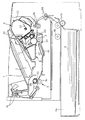
また、現像装置ユニットA(第2の枠体)には、前記静電潜像の現像に用いられる現像剤を収容している現像剤収納容器(現像剤収納部)21と、感光体ドラム10上に形成された静電潜像に現像剤を供給して可視画像を形成させるための現像ローラ(現像担持体)20、現像剤に摩擦帯電電荷を付与し、現像ローラ20の表面上に現像剤層を形成する現像ブレード22、現像ローラ20の半径方向の現像剤漏洩を防止する吹出し防止シート25等が配置されている。ここで、現像ローラ20および現像ブレード22は、枠体41や揺動枠体42で構成される移動枠体40に保持されている。そして、この移動枠体40は、現像剤収納容器21に固定された現像器枠体50に係合ピン80を介して移動可能に組みつけられている。これらの構成については後述する。
【0028】
これらの現像装置ユニットAと感光体ユニットBは、プロセスカートリッジの長手方向両端に設けられた側板(第3の枠体)90、側板(第4の枠体)91(図12参照)によって一体に結合されている。
【0029】
図1および図2において、感光体ドラム10は時計回りに回転駆動される。帯電ローラ11は一定の電圧が印加されており、感光体ドラム10が接触すると接触した感光体ドラム10の感光層表面は一様に帯電する。次いで、光学手段1からの画像情報に応じたレーザービーム光Lを露光開口部2を介して感光体ドラム10上に照射することにより、感光体ドラム10上に静電潜像を形成する。その後、現像手段によって感光体ドラム10上に現像剤像(可視像)が形成される。
【0030】
ここで、現像手段は、現像剤収納容器21内の現像剤を現像剤送り部材(現像剤送り手段)23の回転によって現像ローラ20の方へ送り出す。そして、固定磁石28を内蔵した現像ローラ20を回転させるとともに、現像ブレード22によって摩擦帯電電荷を付与した現像剤層を現像ローラ20の表面に形成する。現像ローラ20は、スペーサーコロ26(図3、図4も参照)を介して一定のクリアランスを保ちつつ付勢バネ(付勢手段)32(図7参照)により感光体ドラム10に押圧されている。そして、表面に形成された現像剤層を感光体ドラム10の現像領域に供給し、その現像剤を前記静電潜像に応じて感光体ドラム10へ転移させることによって現像剤像を形成する。ここで、現像ブレード22は、現像ローラ20の周面の現像剤量を規定するとともに摩擦帯電電荷を付与するものである。また、この現像ローラ20の近傍には現像室内の現像剤を循環させる現像剤撹拌部材(現像剤攪拌手段)24が回転可能に取り付けられている。
【0031】
そして、画像形成装置本体に設けられた転写ローラ3に前記現像剤像と逆極性の電圧を印加して、感光体ドラム10に形成された現像剤像を記録媒体4に転写する。その後に、感光体ドラム10上の残留現像剤は、クリーニング手段14によって除去される。ここで、クリーニング手段14は感光体ドラム10に当接して設けられた弾性クリーニングブレード14aによって感光体ドラム10に残留した現像剤をかき落として除去現像剤容器12に集められる。
【0032】
次に、現像装置を構成する現像ローラを保持する移動枠体および現像器枠体、ならびにそれらの結合関係について、図3ないし図5、図6、図7ないし図9を参照して説明する。
【0033】
移動枠体40は、図3ないし図5に示すように、枠体41と揺動枠体42およびスライド枠体43から構成されている。また、各部材は一体に固定されている。円筒形の現像ローラ20は、図4に詳細に示すように、両端にフランジ部材20a、20bが圧入されており、軸受27、27を介してそれぞれ揺動枠体42とスライド枠体43に回動可能に支持されている。現像ローラ20の内径部には固定磁石28が配設されている。さらに、現像ローラ20の両端には、現像ローラ20とほぼ同軸状に現像ローラ20の外径より規定ギャップ分外径の大きいスペーサーコロ26が摺動可能に設けられている。現像ローラ20上の現像剤層厚を規制する現像ブレード22は、図3に示すように、現像ブレード板金22aに一体成形または接着されている。そして、現像ブレード板金22aは枠体41に固定されて、現像ブレード22の先端は現像ローラ20に当接している(図2も参照)。なお、図3ないし図5において、72は、現像ローラ20のフランジ部材20a上で揺動枠体42の外方に設けられた現像ローラギア(移動枠体駆動力伝達部材)である。現像ローラギア72は、感光体ドラム10のドラムギア71(第1駆動力伝達部材)に噛み合って(図14参照)、該ドラムギア71から回転駆動力を受けて、現像ローラ20を回転させる。
【0034】
現像ローラ20と現像ブレード22を支持する移動枠体40は、図6に示す現像器枠体50内に設置され、図7に示すように組み込まれる。ここで、現像器枠体50は現像剤収納容器21に固定されているが、現像器枠体50は現像剤収納容器21と一体的に形成することもできる。移動枠体40の揺動枠体42には、端部に揺動穴47を有する揺動アーム46が設けられている。一方、現像器枠体50には支持アーム55が延出されており、その端部に固定穴56が設けられている。揺動枠体42と現像器枠体50は、図7に示すように、係合ピン80で揺動可能に係合される。係合ピン80は現像器枠体50の固定穴56に圧入され、揺動枠体42の揺動穴47と係合ピン80は回動可能に形成されている。
【0035】
また、移動枠体40のスライド枠体43は、図8に示すように、その上下面にはスライド方向を規定するスライド平面43a、43bが平行に設けられている。一方、現像器枠体50において、スライド枠体43のスライド平面43a、43bと対向する部位には、図6および図8に示すように、微小なクリアランスをもつ案内平面51a、51bが設けられている。さらに、現像器枠体50と移動枠体40の長手方向の位置決めをするため、現像器枠体50には位置決めボス52(図8参照)が設けられ、枠体41には長手方向のみを決める位置決め長穴41a(図5および図8参照)が設けられている。このように、スライド平面43a、43bと案内平面51a、51bにより、スライド枠体43は、現像器枠体50に対して一定の方向にスライドすることができる。
【0036】
そして、移動枠体40と現像器枠体50の間には付勢バネ32(図7に一方の付勢バネのみを示す)が配設されている。そして、付勢バネ32によって、移動枠体40に保持された現像ローラ20をスペーサーコロ26により一定のクリアランスをもって感光体ドラム10に押圧する。
【0037】
また、移動枠体40のスライド枠体43と現像器枠体50とのスライド関係の他の構成として、図9に示すように形成することもできる。すなわち、スライド枠体43の上下面にスライド方向を規定するスライドレール凸部43c、43dを設け、現像器枠体50の対向する部位にスライドレール凹部51c、51dを設ける。スライドレール凸部43c、43dの先端部43e、43fとスライドレール凹部51c、51dの底面部51e、51fがスライド当接部分となる。こうすることで、スライド面と案内面の面積を小さくすることができ、部品精度の高い面を作り易くなる。併せて、スライド枠体43のレールの短手幅嵌合部を移動枠体40と現像器枠体50の長手方向の位置決めとすることも可能である。
【0038】
以上のように、現像ローラ20を支持する移動枠体40を現像装置ユニットAに移動可能に支持し、付勢バネ32によって現像ローラ20を感光体ドラム10に押圧する構成とすることで、現像剤収納容器21の現像剤量が変動しても、現像ローラ20の感光体ドラム10への押圧力は安定する効果がある。
【0039】
次に、移動枠体40と現像器枠体50間の現像剤の漏洩を防ぐ現像剤シールの構成について、さらに、図5、図6、図10および図11を参照して説明する。
【0040】
移動枠体40の現像器枠体50に対向する面には、図5に示すように、その両端部の枠体42、43の内側の端部短辺部に弾性シール部材44、44が、また、上側長辺部に弾性シール部材45が、それぞれ両面テープで固定されている。なお、図5において、60は現像ローラ20の両端部に対向して配置された磁気シール部材であり、磁気シール部材60については後述する。
【0041】
一方、現像器枠体50には、図6に示すように、両端部に、弾性シール部材44に対応するようにシール受け面57が形成され、上側長辺部には弾性シール部材45に対応するようにシール受け面58が形成されている。移動枠体40を現像器枠体50に組み込むと、図10に示すように、弾性シール部材44および45は、現像器枠体50のシール受け面57および58にそれぞれ当接して圧縮される。これにより、移動枠体40と現像器枠体50間の現像剤の漏洩を防ぐ。図10において、矢印sおよびtは、それぞれ、両端短辺部の弾性シール部材44と上側長辺部の弾性シール部材45の圧縮方向を示す。弾性シール部材45の圧縮方向tが移動枠体40の移動方向とほぼ直角になるように設定されている。こうすることで、圧縮面積が大きい弾性シール部材45の反発力が、現像ローラ20を感光体ドラム10に押圧する押圧力に与える影響を少なくできる。
【0042】
また、現像器枠体50の下側長辺部分54には、図2や図6に示すように、吹出し防止シート25が現像ローラ20に当接するように両面テープで固定されている。これにより、現像ローラ20の下部の半径方向の現像剤漏洩を防止している。
【0043】
次に、現像ローラ20の両端部の現像剤シールについて、図11を参照して説明する。磁気シール部材60は、現像ローラ20の両端部に対向して配置されている(図5には一方の磁気シール部材の一部のみが示されている)。そして、シール部材60は、現像ローラ20の表面に対して所定のクリアランスをもって対向する面60aに複数の磁極を備えており、現像ローラ20との間の磁気カーテンにより現像剤を吸着する。磁気シール部材60は、枠体41に設けられた凹部41bに挿入され、位置決めピン(不図示)を磁気シール部材60の位置決め穴60bに嵌合することで位置決めされる。このように現像ローラ20と磁気シール部材60が同一の枠体41に固定されている。そのため、現像ローラ20が感光体ドラム10の外周に追従して移動枠体40が移動しても、現像ローラ20と磁気シール部材60の間のクリアランスを精度よく一定に設定することができる。このため、磁気シール部材60による現像ローラ20両端部の現像剤シールを良好に構成することができる。
【0044】
次に、現像装置ユニットAと感光体ユニットBを結合する側板の構成について、図12および図13を参照して説明する。
【0045】
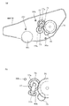
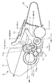
現像装置ユニットAと感光体ユニットBは、図12に示すように、プロセスカートリッジの長手方向両端に設けられた側板90、91によって結合されている。一方の側板90には、図13の(a)に示すように、現像装置ユニットAを取り付けるための位置決め部90a、90bと、感光体ユニットBを取り付けるための位置決め部90c、90dが設けてある。他方の側板91にも同様に位置決め部(不図示)が設けられている。そして、各側板90、91の位置決め部をそれぞれ各ユニットA、Bに設けられた位置決め部と嵌合することで、現像装置ユニットAと感光体ユニットBを一体に結合する。また、一方の側板90には、図13の(a)および(b)に示すように、現像ローラ20から駆動力を現像剤送り部材23や現像剤撹拌部材24に伝達するための駆動系(第2駆動力伝達部材)である第2中間ギア74、現像剤送りギア76、第3中間ギア75および揺動アーム77が支持されている。揺動アーム77は、第2中間ギア74の回転軸芯を揺動中心77aとして揺動しうるように配設され、他端側の揺動ピン77bに第1中間ギア(揺動駆動力伝達部材)73を支持している。また、揺動アーム77の揺動範囲を規制する長穴90hが側板90に形成されている。
【0046】
次に、プロセスカートリッジにおける現像ローラ、現像剤送り部材および現像剤撹拌部材等の駆動系について、図14ないし図16、および図22を参照して説明する。
【0047】
先ず、プロセスカートリッジにおける現像ローラの駆動について、図14および図22を用いて説明する。
【0048】
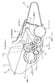
感光体ドラム20の端部に設けられたドラムギア71は、不図示の画像形成装置から駆動ギア70を介して駆動力が伝達され、感光体ドラム10を回転駆動している。また、ドラムギア71は、現像ローラ20と同軸でその端部に設けられた現像ローラギア72(図3〜図5および図7参照)を回転駆動している。図14において、矢印aは、ドラムギア71から現像ローラギア72に駆動力が伝達されるときに現像ローラギア72に働く噛み合い圧力の向きを示す。また、矢印bは、揺動枠体42の揺動中心(係合ピン80)と現像ローラギア72に働く噛み合い圧力の作用点(噛み合い点)を結んだ線である。矢印aが水平線となす角度をθa、矢印bが水平線となす角度をθbとするとき、その関係がθa≧θbとなるように設定する。こうすることで、現像ローラギア72に働く噛み合い圧力は、現像ローラ20を感光体ドラム10に押圧する方向に働く。これにより、スペーサーコロ26が感光体ドラム10から離間してしまうことが無い。
【0049】
また、現像ローラ20の現像ローラギア72をスライド枠体43側に配置し、現像ローラ20をスライド枠体43側で回転駆動する構成とすることも可能であり、この構成を図17に図示する。この構成では、スライド枠体43側に配置された現像ローラギア72が、感光体ドラム10の端部に設けられたドラムギア71に噛み合い、ドラムギア71から駆動力を受ける。図中矢印aは、ドラムギア71から現像ローラギア72に駆動が伝達されるときに現像ローラギア72に働く噛み合い圧力の向きを示している。スライド枠体43のスライド面の角度が矢印aに対して直角、もしくは噛み合い圧力がスライド平面に作用したとき、その力がスライド枠体43を感光体ドラム10方向に押圧する角度に設定するとよい。図17において、Fは現像ローラギア72に働く噛み合い圧力により発生する力である。Fyは力Fの案内平面51bに対して垂直方向の分力、同様にFxは力Fの案内平面51bに対して平行方向の分力である。このFxの向きが感光体ドラム10の方向に向いている。このように、現像ローラ20を駆動する際のギアからの噛み合い圧力の影響で、現像ローラ20は感光体ドラム10へ押圧され、スペーサーコロ26が感光体ドラム10から離間してしまうことが無い。
【0050】
次に、プロセスカートリッジにおける現像剤送り部材23および現像剤撹拌部材24の駆動について図14ないし図16、および図22を用いて説明する。
【0051】
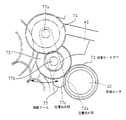
ドラムギア71から駆動力を得た現像ローラギア72は、図14、図15および図22に示すように、第1中間ギア73および第2中間ギア74を介して、現像剤送り部材23と同軸に設けられた現像剤送りギア76を回転駆動させる。そして、現像剤送りギア76から第3中間ギア75を経て、現像剤撹拌部材24と同軸上に設けられた現像剤撹拌ギア78を回転駆動している。なお、第1中間ギア73と第2中間ギア74は、ともに段ギアになっており、現像剤送りギア76や現像剤撹拌ギア78を所定の周速で回転させるための減速を行っている。
【0052】
現像ローラギア72は、前述するように移動枠体40の揺動枠体42に支持されている。そして、現像剤撹拌ギア78は、移動枠体40を移動可能に支持する現像器枠体50に支持されている。一方、第2中間ギア74、現像剤送りギア76および第3中間ギア75は、側板90(図13の(a)参照)に支持されている。そして、第1中間ギア73は、第2中間ギア74の支持軸を揺動中心77aとする揺動アーム77(揺動駆動力伝達部材支持部材)の他端側の揺動ピン77bに支持されている。また、揺動ピン77bは側板90に設けられた長穴90hの範囲内で揺動可能な構成になっている。したがって、第1中間ギア73は、揺動アーム77の揺動中心77aを中心に揺動しうるように構成されて、現像ローラギア72に対して揺動可能である。第1中間ギア73と第2中間ギア74は、揺動アーム77によって中心間距離が一定になっている。
【0053】
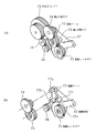
第1中間ギア73の現像ローラギア72に対する位置決めについて、図15および図16を用いて説明する。図15の(a)および(b)は、各ギア72〜76、78の取り付け状態および揺動アーム77の位置決め状態を表す斜視図である。また、図16は揺動アーム77の位置決め状態を拡大して示す図である。
【0054】
揺動中心77aを中心に揺動する揺動アーム77は、図15の(b)や図16に示すように、その他端部に揺動ピン77bと同心円状に設けられた位置決め部77cが形成され、揺動ピン77bで第1中間ギア73を支持している。そして、駆動力が伝達されると、第1中間ギア73には図16に示すように現像ローラギア72と第2中間ギア74の噛み合いによって、圧力F1 が作用する。このF1 の分力F1 xによって、第1中間ギア73は現像ローラギア72の噛み合いを維持する方向に、揺動中心77aを中心に力を受ける。そして、位置決め部77cが、揺動枠体42に設けられた、現像ローラ20と同心円の位置決め部42aに突き当たる。よって、第1中間ギア73と現像ローラギア72の中心間距離を一定に保持されて、確実に噛み合うことになる。
【0055】
このような構成にすることで、揺動枠体42に支持された現像ローラギア72が、現像剤収納容器21に固定的に取り付けられた現像器枠体50、感光体ユニットB、あるいは側板90に対して、位置が変動しても、現像ローラギア72と第1中間ギア73の中心間距離を保たれ、噛み合いは確実に維持することが可能となる。そのために、現像ローラギア72、第1中間ギア73の摩耗の軽減を図り、現像装置の駆動トルクの増大を防ぐ効果も生じる。
【0056】
前述した実施形態の駆動系(図13ないし図16参照)では、現像ローラギア72と第1中間ギア73の中心間距離を決めるために、揺動アーム77の位置決め部77cを揺動枠体42に設けた位置決め部42aに突き当てる構成とした。しかし、図18や図19に図示するような構成とすることもできる。すなわち、図18においては、揺動アーム77の位置決め部77cを突き当てる位置決め部(移動枠体位置決め部)72aは、現像ローラギア72と一体で同心状に形成された部材を用いている。また、図19においては、揺動アーム77の位置決め部77cが現像ローラ20の軸部(移動枠体位置決め部)に当接して位置決めされる。上記の構成でも同様の効果を得られることができる。
【0057】
また、前述した実施形態の駆動系(図13ないし図16参照)では、揺動アームの支持構成において、第1中間ギア73を支持する揺動アーム77は側板90に軸支されている。しかし、図20に図示するように、第1中間ギア73および揺動アーム77xを揺動枠体42に支持させることもできる。現像ローラギア72は同じ揺動枠体42に支持されており、揺動枠体42が移動しても第1中間ギア73と現像ローラギア72は常に確実に噛み合っている。そして、第1中間ギア73の支持軸を揺動中心77xaとするように揺動アーム77xを揺動枠体42に取り付け、揺動アーム77xの他端に設けられた揺動ピン77xbに第2中間ギア74を支持させる。この構成により、第2中間ギア74は、第1中間ギア73と同軸状に設けられた揺動中心77xaを中心に揺動する揺動アーム77xにより矢印のように揺動可能となる。そして、駆動力が伝達されると、第2中間ギア74が、第1の中間ギア73および現像剤送りギア76から受ける反力によって、現像剤送りギア76の方向に押圧される。そして、揺動アーム77xの位置決め部と、各枠体に設けた位置決め部と当接する。また、図18および図19と同様に現像剤送りギア(第2枠体駆動力伝達部材)76に設けた位置決め部(不図示)、または現像剤送りギア(第2枠体駆動力伝達部材)76を支持する軸(不図示)と当接する構成にしても良い。よって、第2中間ギア74と現像剤送りギア76の中心間距離は一定に保たれ、確実に噛み合うことができる。そのため、第2中間ギア74や現像剤送りギア76の摩耗の軽減を図り、現像装置の駆動トルクの増大を防ぐ効果を生じる。
【0058】
また、図21に図示するように、第2中間ギア74および揺動アーム77yを現像器枠体50あるいは現像剤収納容器21に支持させることもできる。この場合には、第1中間ギア73は、揺動アーム77yの他端に設けられた揺動ピン77ybに支持させる。第1中間ギア73は、第2中間ギア74と同軸状に設けられた揺動アーム77yの揺動中心77yaに対し矢印のように揺動可能となる。そして、揺動アーム77yの位置決め部を突き当てる位置決め部として、前述した図13ないし図16に示す実施形態と同様に、揺動枠体42に設けられた位置決め部を用いることができる。また、図18、図19と同様に現像ローラギア72に設けた位置決め部(不図示)や現像ロールギア72を支持する軸と当接させても良い。
【0059】
よって、揺動枠体42に支持された現像ローラギア72が、現像剤収納容器21に固定的に取り付けられた現像器枠体50、感光体ユニットB、あるいは側板90に対して、位置が変動しても、現像ローラギア72と第1中間ギア73の中心間距離を保たれ、噛み合いは確実に維持される。そのために、現像ローラギア72や第1中間ギア73の摩耗の軽減を図り、現像装置の駆動トルクの増大を防ぐ効果も生じる。
【0060】
また、本実施形態では、第1駆動力伝達部材、第2駆動力伝達部材、移動枠体伝達部材の各伝達部材としてギアが示されているが、摩擦車あるいはプーリーおおびベルト等の駆動力伝達部材でも良い。
【0061】
なお、本実施形態においては、現像剤担持体として現像ローラが示されているが、現像ベルト等を用いたものでも良い。
【0062】
【発明の効果】
以上説明したように、本発明によれば、現像剤担持体を支持する移動枠体を第2の枠体に移動可能に支持し、付勢部材によって現像剤担持体を電子写真感光体に押圧する構成とすることで、現像剤収納部の現像剤量が変動しても、現像剤担持体の電子写真感光体への押圧力は安定する。また、現像剤送り手段を駆動させるために、第2の枠体に設けられた第2駆動力伝達部材と、前記移動枠体との駆動力の伝達を行う揺動駆動力伝達部材を設ける。そして、前記揺動駆動力伝達部材を支持する揺動駆動力伝達部材支持部材を揺動可能に支持することで、駆動力の伝達を円滑にし、また駆動トルクの増大を防ぐことができる。
【図面の簡単な説明】
【図1】本発明に係る電子写真画像形成装置の構成を示す概略構成図である。
【図2】本発明に係る電子写真画像形成装置に着脱可能なプロセスカートリッジの縦断面図である。
【図3】本発明に係るプロセスカートリッジにおける現像ローラを保持する移動枠体の構成を示す斜視図である。
【図4】本発明に係るプロセスカートリッジにおける現像ローラおよび現像ローラを支持する揺動枠体とスライド枠体の構成を示す断面図である。
【図5】本発明に係るプロセスカートリッジにおける現像ローラを保持する移動枠体を裏面側からみた斜視図であり、移動枠体のシール部材を示す。
【図6】本発明に係るプロセスカートリッジにおける移動枠体を組み込む現像器枠体を示す斜視図である。
【図7】本発明に係るプロセスカートリッジにおける現像器枠体に移動枠体を組み込んだ状態を示す現像装置ユニットの斜視図である。
【図8】本発明に係るプロセスカートリッジにおける移動枠体のスライド枠体と現像器枠体の関係を示す斜視図である。
【図9】本発明に係るプロセスカートリッジにおける移動枠体のスライド枠体と現像器枠体の関係の他の例を示す斜視図である。
【図10】本発明に係るプロセスカートリッジにおける現像器枠体に移動枠体を組み込んだ状態における端部の枠体シールを説明するための模式図である。
【図11】本発明に係るプロセスカートリッジにおける現像器枠体に移動枠体を組み込んだ状態における現像ローラの両端部の磁気シール部を示す説明するための模式図である。
【図12】本発明に係るプロセスカートリッジにおける現像装置ユニットと感光体ユニットを側板によって結合した状態を示す外観斜視図である。
【図13】(a)は現像装置ユニットと感光体ユニットを結合する側板を示す図であり、(b)はその一部を拡大して示す図である。
【図14】本発明に係るプロセスカートリッジにおける現像ローラ等の駆動系を示す概略図である。
【図15】(a)および(b)は、それぞれ、現像ローラ等の駆動系の各ギアの取り付け状態および揺動アームの位置決め状態を表す斜視図である。
【図16】本発明に係るプロセスカートリッジにおける現像ローラ等の駆動系の揺動アームの位置決め状態を拡大して示す図である。
【図17】本発明に係るプロセスカートリッジにおける移動枠体のスライド枠体側にギアを配置した例を説明するための図である。
【図18】本発明に係るプロセスカートリッジにおける駆動系の揺動アームの他の位置決め状態を拡大して示す図である。
【図19】本発明に係るプロセスカートリッジにおける駆動系の揺動アームの他の位置決め状態を拡大して示す図である。
【図20】本発明に係るプロセスカートリッジにおける現像ローラ等の駆動系の他の例を示す概略図である。
【図21】本発明に係るプロセスカートリッジにおける現像ローラ等の駆動系のさらに他の例を示す概略図である。
【図22】本発明に係るプロセスカートリッジにおける現像ローラ等の駆動系を示す概略図である。
【符号の説明】
A 現像装置ユニット
B 感光体ユニット
L レーザービーム光
3 転写ローラ
4 記録媒体
5 定着手段 10 感光体ドラム
11 帯電手段
12 除去現像剤容器
14 クリーニング手段
20 現像ローラ
20a、20b フランジ
21 現像剤収納容器
22 現像ブレード
22a 現像ブレード板金
23 現像剤送り部材
25 吹出し防止シート
26 スペーサーコロ
27 軸受
28 固定磁石
32 付勢バネ
40 移動枠体
41 枠体
42 揺動枠体
42a 位置決め部
43 スライド枠体
44 弾性シール部材
45 弾性シール部材
46 揺動アーム
47 揺動穴
50 現像器枠体
55 支持アーム
56 固定穴
57 シール受け面
58 シール受け面
60 磁気シール部材
70 駆動ギア
71 ドラムギア
72 現像ローラギア
72a 位置決め部
73 第1中間ギア
74 第2中間ギア
75 第3中間ギア
76 現像剤送りギア
77 揺動アーム
77a 揺動中心
77b 揺動ピン
77c 位置決め部
77x 揺動アーム
77xa 揺動中心
77xb 揺動ピン
77y 揺動アーム
77ya 揺動中心
77yb 揺動ピン
78 現像剤撹拌ギア
80 係合ピン
90、91 側板[0001]
BACKGROUND OF THE INVENTION
The present invention relates to a process cartridge and an electrophotographic image forming apparatus using the process cartridge.
[0002]
Here, examples of the electrophotographic image forming apparatus include an electrophotographic copying machine, an electrophotographic printer (for example, an LED printer, a laser beam printer, etc.), an electrophotographic facsimile apparatus, and an electrophotographic word processor.
[0003]
The process cartridge is a cartridge in which at least the developing means (developer carrying member) and the electrophotographic photosensitive member are integrated into a cartridge so as to be detachable from the image forming apparatus main body.
[0004]
[Prior art]
Conventionally, in an electrophotographic image forming apparatus using an electrophotographic image forming process, an electrophotographic photosensitive drum and process means acting on the electrophotographic photosensitive drum are integrally formed into a cartridge, and the cartridge is formed into an electrophotographic image. A process cartridge system that can be attached to and detached from the apparatus main body is employed.
[0005]
According to this type of process cartridge system, the user can perform maintenance of the apparatus by himself / herself without depending on the service person, so that the operability can be remarkably improved. Therefore, this process cartridge system is widely used in electrophotographic image forming apparatuses.
[0006]
This type of conventional process cartridge includes, for example, a photoreceptor unit and a developing device unit. The photosensitive unit includes an electrophotographic photosensitive drum (hereinafter also simply referred to as a photosensitive drum) that forms an electrostatic latent image, a charging roller that is a charging unit for uniformly charging the surface of the photosensitive layer, and a recording medium. Cleaning means is disposed for scraping off the residual developer adhering to the photosensitive drum without being transferred to the surface of the photosensitive drum and storing it in the removed developer container.
[0007]
Further, the developing device unit includes a developer container for containing a developer, and a developer carrying member for supplying a developer to the electrostatic latent image formed on the photosensitive drum to form a visible image. A roller, a developing blade that imparts triboelectric charge to the developer and forms a developer layer on the surface of the developing roller, a blowout prevention sheet that prevents developer leakage in the radial direction of the developing roller, and the like are disposed. The developing roller and the developing blade are held by a developing device frame, and the developing device frame is coupled to a developer container to constitute a developing device unit.
[0008]
The developing device unit and the photoconductor unit are rotatably coupled by an engaging pin, and a biasing spring is provided between the developing device unit and the photoconductor unit.
[0009]
Further, the drum gear provided at the end of the photosensitive drum is driven to rotate by rotating the photosensitive drum through a driving force transmitted through a driving gear disposed in the image forming apparatus. The drum gear rotationally drives a developing roller gear provided coaxially with the developing roller. The drive connection to the developer feeding member that feeds the developer in the developer container toward the developing roller is coaxial with the developer feeding member by decelerating the driving force of the developing roller gear via an intermediate gear or the like. The provided developer feed gear is driven to rotate. The driving force from the developer feeding gear rotates and drives the developer stirring gear provided coaxially with the developer stirring member via an intermediate gear or the like.
[0010]
[Problems to be solved by the invention]
However, in the conventional developing device described above, the amount of developer in the developer accommodating portion fluctuates due to developer consumption associated with image formation, so that the pressure for pressing the developing roller as the developer carrying member against the photosensitive drum is increased. fluctuate. Along with this, there is a problem that the driving torque when the drum gear and the developing roller gear mesh with each other fluctuates.
[0011]
Therefore, the present invention has been made in view of the unsolved problems of the prior art, and is a process cartridge and an electrophotographic image that can stabilize the pressing force of the developer carrier to the electrophotographic photosensitive member. An object of the present invention is to provide a forming apparatus.
[0012]
Another object of the present invention is to provide a process cartridge and an electrophotographic image forming apparatus capable of smoothly transmitting a driving force and preventing an increase in driving torque.
[0013]
[Means for Solving the Problems]
In order to achieve the above object, a process cartridge of the present invention develops an electrophotographic photosensitive member and an electrostatic latent image formed on the electrophotographic photosensitive member in a process cartridge that is detachable from an electrophotographic image forming apparatus main body. A developer carrying member, a developer containing portion for containing the developer used for developing the electrostatic latent image by the developer carrying member, and a developer feeding means for conveying the developer to the developer carrying member. A first frame that supports the electrophotographic photosensitive member, a second frame that has the developer accommodating portion, and supports the developer carrier and moves relative to the second frame. A movable moving frame, a biasing member for pressing the developer carrying member supported by the moving frame to the electrophotographic photosensitive member, and Electrophotographic image formation In order to receive a driving force from the apparatus main body and transmit the driving force to the electrophotographic photosensitive member, a first driving force transmitting member provided in a first frame and a developer feeding means Said In order to transmit the driving force, a second driving force transmission member provided on the second frame and the driving force received from the first driving force transmission member to the developing carrier. Said In order to transmit the driving force, the moving frame body driving force transmission member provided in the moving frame body, Moving frame From the driving force transmission member Second A swing driving force transmitting member that transmits the driving force to the driving force transmitting member; and a swing driving force transmitting member support member that supports the swing driving force transmitting member. The member supporting member is swingably supported.
[0014]
In the process cartridge of the present invention, Further, the process cartridge includes a third frame that joins the first frame and the second frame at one end side in the longitudinal direction of the first frame and the second frame. Have a body, The swing driving force transmission member support member is the third frame body. In It is preferably supported.
[0015]
In the process cartridge of the present invention, the first driving force transmission member is connected to the apparatus main body. Said When the driving force is transmitted, it is preferable that the support member positioning portion provided on the swing driving force transmitting member support member abuts on the moving frame body positioning portion provided on the moving frame body, or From the apparatus main body to the first driving force transmission member Said When the driving force is transmitted, it is preferable that the support member positioning portion provided on the swing driving force transmitting member support member abuts on the second frame body positioning portion provided on the second frame body.
[0016]
In the process cartridge of the present invention, the swing driving force transmission member and the movable frame body driving force transmission member are gears, and the movable frame body positioning portion is the movable frame body. Driving force transmission member Or the moving frame provided on the member Driving force transmission member The swing driving force transmission member and the second frame body driving force transmission member are gears, and the second frame positioning portion is the second frame body. Driving force transmission member Or the second frame body Driving force transmission member It is preferably a shaft that supports
[0017]
In the process cartridge according to the aspect of the invention, it is preferable that the second driving force transmission member transmits a driving force to a developer stirring unit that circulates the developer, and the moving frame body includes the first or first moving frame. It is preferable that the driving side is swingably held with respect to the frame 2 and the non-driving side is slidable.
[0019]
[Action]
According to the process cartridge and the electrophotographic image forming apparatus of the present invention, the movable frame that supports the developer carrier is movably supported, and the developer carrier is pressed against the electrophotographic photosensitive member by the biasing member. To do. As a result, the developer carrying member can be stably pressed against the electrophotographic photosensitive member even if the amount of the developer in the developer accommodating portion varies.
[0020]
In order to drive the developer feeding means, a second driving force transmitting member provided on the second frame and a swing driving force transmitting member for transmitting driving force to the movable frame are provided. Further, by supporting the swing driving force transmission member supporting member that supports the swing driving force transmitting member so as to be swingable, it is possible to smoothly transmit the driving force and prevent an increase in driving torque.
[0021]
DETAILED DESCRIPTION OF THE INVENTION
Embodiments of a process cartridge and an electrophotographic image forming apparatus according to the present invention will be described below with reference to the drawings. In addition, the code | symbol in an explanatory note is for referring drawings, and does not limit a structure.
[0022]
First, an embodiment of an electrophotographic image forming apparatus in which a process cartridge constructed according to the present invention is detachably mounted will be described with reference to FIG. 1 and FIG. The electrophotographic image forming apparatus is an apparatus that forms an image on a recording medium such as recording paper, an OHP sheet, or a cloth using an electrophotographic image forming process. For example, an electrophotographic copying machine, an electrophotographic printer (for example, an LED printer, a laser beam printer, etc.), an electrophotographic facsimile machine, an electrophotographic word processor, and the like are included. In this embodiment, an electrophotographic laser beam printer will be described as an example.
[0023]
In FIG. 1, the surface of a drum-shaped electrophotographic photosensitive member (hereinafter also simply referred to as a photosensitive drum) 10 is uniformly charged by a charging
[0024]
On the other hand, in synchronization with the formation of the developer image, the recording medium 4 set in the
[0025]
The recording medium 4 to which the developer image has been transferred is conveyed to the fixing unit 5 by the
[0026]
The process cartridge which can be attached to and detached from the electrophotographic image forming apparatus main body is configured as shown in FIG. That is, the photosensitive unit B (first frame) of the process cartridge includes a
[0027]
Further, the developing device unit A (second frame) includes a developer storage container (developer storage portion) 21 that stores a developer used for developing the electrostatic latent image, and a
[0028]
The developing device unit A and the photosensitive unit B are integrated by a side plate (third frame) 90 and a side plate (fourth frame) 91 (see FIG. 12) provided at both ends in the longitudinal direction of the process cartridge. Are combined.
[0029]
1 and 2, the
[0030]
Here, the developing means feeds the developer in the
[0031]
Then, a voltage having a polarity opposite to that of the developer image is applied to a
[0032]
Next, the moving frame and the developing device frame that hold the developing roller constituting the developing device, and their coupling relationship will be described with reference to FIGS. 3 to 5, 6, and 7 to 9. FIG.
[0033]
As shown in FIGS. 3 to 5, the moving
[0034]
The moving
[0035]
Further, as shown in FIG. 8, the
[0036]
A biasing spring 32 (only one biasing spring is shown in FIG. 7) is disposed between the moving
[0037]
Further, as another configuration of the sliding relationship between the
[0038]
As described above, the moving
[0039]
Next, the configuration of the developer seal that prevents leakage of the developer between the moving
[0040]
As shown in FIG. 5,
[0041]
On the other hand, as shown in FIG. 6, the developing
[0042]
Further, as shown in FIGS. 2 and 6, the
[0043]
Next, the developer seals at both ends of the developing
[0044]
Next, the structure of the side plate that couples the developing device unit A and the photoreceptor unit B will be described with reference to FIGS.
[0045]
As shown in FIG. 12, the developing device unit A and the photosensitive unit B are coupled by
[0046]
Next, drive systems such as a developing roller, a developer feeding member, and a developer stirring member in the process cartridge will be described with reference to FIGS. 14 to 16 and FIG.
[0047]
First, driving of the developing roller in the process cartridge will be described with reference to FIGS.
[0048]
The
[0049]
Further, the developing
[0050]
Next, driving of the
[0051]
The developing
[0052]
The developing
[0053]
The positioning of the first
[0054]
As shown in FIG. 15B and FIG. 16, the
[0055]
With this configuration, the developing
[0056]
In the drive system of the above-described embodiment (see FIGS. 13 to 16), the
[0057]
In the drive system of the above-described embodiment (see FIGS. 13 to 16), the
[0058]
Further, as shown in FIG. 21, the second
[0059]
Therefore, the position of the developing
[0060]
In the present embodiment, gears are shown as the transmission members of the first driving force transmission member, the second driving force transmission member, and the moving frame body transmission member. However, the driving force of a friction wheel, a pulley, a belt, and the like is shown. A transmission member may be used.
[0061]
In this embodiment, a developing roller is shown as the developer carrying member, but a developing belt or the like may be used.
[0062]
【The invention's effect】
As described above, according to the present invention, the movable frame supporting the developer carrying member is movably supported by the second frame, and the developer carrying member is pressed against the electrophotographic photosensitive member by the urging member. By adopting such a configuration, even if the amount of developer in the developer accommodating portion varies, the pressing force of the developer carrying member to the electrophotographic photosensitive member is stabilized. In order to drive the developer feeding means, a second driving force transmitting member provided on the second frame and a swing driving force transmitting member for transmitting driving force to the movable frame are provided. Further, by supporting the swing driving force transmission member supporting member that supports the swing driving force transmitting member so as to be swingable, it is possible to smoothly transmit the driving force and to prevent an increase in driving torque.
[Brief description of the drawings]
FIG. 1 is a schematic configuration diagram showing a configuration of an electrophotographic image forming apparatus according to the present invention.
FIG. 2 is a longitudinal sectional view of a process cartridge that can be attached to and detached from an electrophotographic image forming apparatus according to the present invention.
FIG. 3 is a perspective view illustrating a configuration of a moving frame body that holds a developing roller in a process cartridge according to the present invention.
FIG. 4 is a cross-sectional view illustrating a configuration of a developing roller and a swing frame body that supports the developing roller and a slide frame body in the process cartridge according to the present invention.
FIG. 5 is a perspective view of the moving frame body that holds the developing roller in the process cartridge according to the present invention as seen from the back side, and shows a seal member of the moving frame body.
FIG. 6 is a perspective view showing a developing device frame incorporating a moving frame in the process cartridge according to the present invention.
FIG. 7 is a perspective view of the developing device unit showing a state in which the moving frame is incorporated in the developing device frame in the process cartridge according to the present invention.
FIG. 8 is a perspective view showing the relationship between the slide frame of the moving frame and the developing device frame in the process cartridge according to the present invention.
FIG. 9 is a perspective view showing another example of the relationship between the slide frame of the moving frame and the developing device frame in the process cartridge according to the present invention.
FIG. 10 is a schematic diagram for explaining a frame seal at an end in a state where a moving frame is incorporated in a developing device frame in a process cartridge according to the present invention.
FIG. 11 is a schematic diagram for explaining magnetic seal portions at both ends of the developing roller in a state in which the moving frame is incorporated in the developing device frame in the process cartridge according to the present invention.
FIG. 12 is an external perspective view showing a state in which the developing device unit and the photoconductor unit in the process cartridge according to the present invention are coupled by a side plate.
FIG. 13A is a view showing a side plate that joins the developing device unit and the photosensitive unit, and FIG. 13B is an enlarged view of a part thereof.
FIG. 14 is a schematic view showing a drive system such as a developing roller in the process cartridge according to the present invention.
FIGS. 15A and 15B are perspective views showing an attachment state of each gear of a driving system such as a developing roller and a positioning state of a swing arm, respectively. FIGS.
FIG. 16 is an enlarged view showing a positioning state of a swing arm of a driving system such as a developing roller in the process cartridge according to the present invention.
FIG. 17 is a view for explaining an example in which a gear is arranged on the slide frame side of the moving frame in the process cartridge according to the present invention.
FIG. 18 is an enlarged view showing another positioning state of the swing arm of the drive system in the process cartridge according to the present invention.
FIG. 19 is an enlarged view showing another positioning state of the swing arm of the drive system in the process cartridge according to the present invention.
FIG. 20 is a schematic view showing another example of a drive system such as a developing roller in the process cartridge according to the present invention.
FIG. 21 is a schematic view showing still another example of a drive system such as a developing roller in the process cartridge according to the present invention.
FIG. 22 is a schematic view showing a drive system such as a developing roller in the process cartridge according to the present invention.
[Explanation of symbols]
A Developer unit
B Photoconductor unit
L Laser beam light
3 Transfer roller
4 recording media
5 Fixing means 10 Photosensitive drum
11 Charging means
12 Removed developer container
14 Cleaning means
20 Developing roller
20a, 20b Flange
21 Developer storage container
22 Development blade
22a Development blade sheet metal
23 Developer feed member
25 Blowout prevention sheet
26 Spacer roller
27 Bearing
28 Fixed magnet
32 Biasing spring
40 Moving frame
41 Frame
42 Swing frame
42a Positioning part
43 Slide frame
44 Elastic seal member
45 Elastic seal member
46 Swing arm
47 Swing hole
50 Developer frame
55 Support arm
56 fixing hole
57 Seal receiving surface
58 Seal receiving surface
60 Magnetic seal members
70 Drive gear
71 Drum Gear
72 Developing roller gear
72a Positioning part
73 1st intermediate gear
74 Second intermediate gear
75 3rd intermediate gear
76 Developer feed gear
77 Swing arm
77a Oscillation center
77b Swing pin
77c Positioning part
77x swing arm
77xa swing center
77xb swing pin
77y swing arm
77ya swing center
77yb swing pin
78 Developer stirring gear
80 engaging pin
90, 91 side plate
Claims (10)
電子写真感光体と、
前記電子写真感光体に形成された静電潜像を現像するための現像剤担持体と、
前記現像剤担持体による前記静電潜像の現像に用いられる現像剤を収納する現像剤収納部と、
前記現像剤を前記現像担持体へ搬送する現像剤送り手段と、
前記電子写真感光体を支持する第1の枠体と、
前記現像剤収納部を有する第2の枠体と、
前記現像剤担持体を支持し、前記第2の枠体に対して移動可能な移動枠体と、
前記移動枠体に支持された前記現像剤担持体を前記電子写真感光体へ押圧するための付勢部材と、
前記電子写真画像形成装置本体から駆動力を受けて前記電子写真感光体に駆動力を伝達するために、第1の枠体に設けられた第1駆動力伝達部材と、
前記現像剤送り手段に前記駆動力を伝達させるために、前記第2の枠体に設けられた第2駆動力伝達部材と、
前記第1駆動力伝達部材から前記駆動力を受けて前記現像担持体に前記駆動力を伝達するために、前記移動枠体に設けられた移動枠体駆動力伝達部材と、
前記移動枠体駆動力伝達部材から前記第2駆動力伝達部材へ前記駆動力の伝達を行う揺動駆動力伝達部材と、
前記揺動駆動力伝達部材を支持する揺動駆動力伝達部材支持部材と、を有し、
前記揺動駆動力伝達部材支持部材が揺動可能に支持されていることを特徴とするプロセスカートリッジ。In a process cartridge that can be attached to and detached from the electrophotographic image forming apparatus main body,
An electrophotographic photoreceptor;
A developer carrying member for developing the electrostatic latent image formed on the electrophotographic photosensitive member;
A developer accommodating portion for accommodating a developer used for developing the electrostatic latent image by the developer carrying member;
Developer feeding means for transporting the developer to the development carrier;
A first frame for supporting the electrophotographic photosensitive member;
A second frame having the developer accommodating portion;
A movable frame that supports the developer carrier and is movable with respect to the second frame;
An urging member for pressing the developer carrying member supported by the moving frame against the electrophotographic photosensitive member;
A first driving force transmission member provided in a first frame for receiving a driving force from the electrophotographic image forming apparatus main body and transmitting the driving force to the electrophotographic photosensitive member;
To transmit the driving force to the developer feed means, second driving force transmitting member provided on said second frame,
In order to transmit the driving force to the developing bearing member receives the driving force from the first driving force transmission member, a movable frame driving force transmission member provided on the movable frame,
A swing driving force transmission member that transmits the driving force from the moving frame body driving force transmission member to the second driving force transmission member;
A swing driving force transmission member support member that supports the swing driving force transmission member;
A process cartridge, wherein the swing driving force transmission member support member is swingably supported.
Priority Applications (1)
| Application Number | Priority Date | Filing Date | Title |
|---|---|---|---|
| JP2001331832A JP3937802B2 (en) | 2001-10-30 | 2001-10-30 | Process cartridge |
Applications Claiming Priority (1)
| Application Number | Priority Date | Filing Date | Title |
|---|---|---|---|
| JP2001331832A JP3937802B2 (en) | 2001-10-30 | 2001-10-30 | Process cartridge |
Publications (3)
| Publication Number | Publication Date |
|---|---|
| JP2003131545A JP2003131545A (en) | 2003-05-09 |
| JP2003131545A5 JP2003131545A5 (en) | 2005-06-30 |
| JP3937802B2 true JP3937802B2 (en) | 2007-06-27 |
Family
ID=19147334
Family Applications (1)
| Application Number | Title | Priority Date | Filing Date |
|---|---|---|---|
| JP2001331832A Expired - Lifetime JP3937802B2 (en) | 2001-10-30 | 2001-10-30 | Process cartridge |
Country Status (1)
| Country | Link |
|---|---|
| JP (1) | JP3937802B2 (en) |
Families Citing this family (10)
| Publication number | Priority date | Publication date | Assignee | Title |
|---|---|---|---|---|
| KR100498045B1 (en) * | 2003-07-14 | 2005-07-01 | 삼성전자주식회사 | Device of development for image forming apparatus |
| JP4856891B2 (en) * | 2005-05-09 | 2012-01-18 | キヤノン株式会社 | Developing roller, developing device, and process cartridge |
| JP4695445B2 (en) * | 2005-06-16 | 2011-06-08 | 株式会社リコー | Process cartridge and image forming apparatus |
| JP4765501B2 (en) * | 2005-09-14 | 2011-09-07 | ブラザー工業株式会社 | Image forming apparatus and developing cartridge |
| JP5585067B2 (en) * | 2009-12-14 | 2014-09-10 | 富士ゼロックス株式会社 | Detachable unit and image forming apparatus |
| JP5545544B2 (en) * | 2010-09-16 | 2014-07-09 | 株式会社リコー | Driving device, fixing device, and image forming apparatus |
| JP2014092651A (en) * | 2012-11-02 | 2014-05-19 | Ricoh Co Ltd | Process cartridge, and image forming apparatus |
| CN107918259B (en) * | 2016-10-06 | 2023-12-22 | 江西亿铂电子科技有限公司 | Control mechanism and developing box |
| CN107918266B (en) * | 2016-10-06 | 2020-10-09 | 江西亿铂电子科技有限公司 | Processing box with driving assembly |
| CN108227449A (en) * | 2018-02-01 | 2018-06-29 | 珠海联合天润打印耗材有限公司 | A kind of handle box and its imaging device |
-
2001
- 2001-10-30 JP JP2001331832A patent/JP3937802B2/en not_active Expired - Lifetime
Also Published As
| Publication number | Publication date |
|---|---|
| JP2003131545A (en) | 2003-05-09 |
Similar Documents
| Publication | Publication Date | Title |
|---|---|---|
| US11774905B2 (en) | Electrophotographic image forming apparatus | |
| JP3969805B2 (en) | Electrophotographic image forming apparatus | |
| JP3595798B2 (en) | Process cartridge and electrophotographic image forming apparatus | |
| JP6907296B2 (en) | Image forming apparatus and cartridge used for this | |
| JP3969990B2 (en) | Developing device, process cartridge, and image forming apparatus | |
| JP3554164B2 (en) | Process cartridge, electrophotographic image forming apparatus and seal member | |
| JP2004012523A (en) | Developing device, developing cartridge, process cartridge, and image forming apparatus | |
| JP6465631B2 (en) | Cartridge and image forming apparatus | |
| US20210124304A1 (en) | Developing device having restricted movement, process cartridge and image forming apparatus | |
| JP3937802B2 (en) | Process cartridge | |
| JP7146410B2 (en) | Cartridge and image forming apparatus using the same | |
| JP3080522B2 (en) | Toner supply container, cartridge, and image forming apparatus | |
| JPH10186851A (en) | Image forming device | |
| JP3913034B2 (en) | Process cartridge | |
| JP4011882B2 (en) | Developing device, process cartridge, and image forming apparatus | |
| JP2017076112A (en) | Cartridge and image forming apparatus | |
| JP6887792B2 (en) | Development unit and process cartridge | |
| JP2006146102A (en) | Developing apparatus, process cartridge, and electrophotographic image forming apparatus | |
| JP2003076144A (en) | Developing device, process cartridge, and electrohotographic image forming device | |
| JP4397727B2 (en) | Image forming apparatus | |
| JP4681847B2 (en) | Electrophotographic image forming apparatus | |
| JP2017223770A (en) | Process cartridge and image forming apparatus | |
| JP2021196456A (en) | Cartridge and image forming apparatus | |
| JP5136528B2 (en) | Image forming apparatus | |
| JP2019204116A (en) | Cartridge and image forming apparatus using the same |
Legal Events
| Date | Code | Title | Description |
|---|---|---|---|
| A521 | Written amendment |
Free format text: JAPANESE INTERMEDIATE CODE: A523 Effective date: 20041021 |
|
| A621 | Written request for application examination |
Free format text: JAPANESE INTERMEDIATE CODE: A621 Effective date: 20041021 |
|
| A977 | Report on retrieval |
Free format text: JAPANESE INTERMEDIATE CODE: A971007 Effective date: 20061116 |
|
| A131 | Notification of reasons for refusal |
Free format text: JAPANESE INTERMEDIATE CODE: A131 Effective date: 20061121 |
|
| A521 | Written amendment |
Free format text: JAPANESE INTERMEDIATE CODE: A523 Effective date: 20061226 |
|
| TRDD | Decision of grant or rejection written | ||
| A01 | Written decision to grant a patent or to grant a registration (utility model) |
Free format text: JAPANESE INTERMEDIATE CODE: A01 Effective date: 20070309 |
|
| A61 | First payment of annual fees (during grant procedure) |
Free format text: JAPANESE INTERMEDIATE CODE: A61 Effective date: 20070319 |
|
| R150 | Certificate of patent or registration of utility model |
Ref document number: 3937802 Country of ref document: JP Free format text: JAPANESE INTERMEDIATE CODE: R150 Free format text: JAPANESE INTERMEDIATE CODE: R150 |
|
| FPAY | Renewal fee payment (event date is renewal date of database) |
Free format text: PAYMENT UNTIL: 20110406 Year of fee payment: 4 |
|
| FPAY | Renewal fee payment (event date is renewal date of database) |
Free format text: PAYMENT UNTIL: 20130406 Year of fee payment: 6 |
|
| FPAY | Renewal fee payment (event date is renewal date of database) |
Free format text: PAYMENT UNTIL: 20130406 Year of fee payment: 6 |
|
| FPAY | Renewal fee payment (event date is renewal date of database) |
Free format text: PAYMENT UNTIL: 20140406 Year of fee payment: 7 |