JP4803544B2 - Audio / video playback apparatus and method - Google Patents
Audio / video playback apparatus and method Download PDFInfo
- Publication number
- JP4803544B2 JP4803544B2 JP2001573477A JP2001573477A JP4803544B2 JP 4803544 B2 JP4803544 B2 JP 4803544B2 JP 2001573477 A JP2001573477 A JP 2001573477A JP 2001573477 A JP2001573477 A JP 2001573477A JP 4803544 B2 JP4803544 B2 JP 4803544B2
- Authority
- JP
- Japan
- Prior art keywords
- audio
- video
- metadata
- video material
- recording medium
- Prior art date
- Legal status (The legal status is an assumption and is not a legal conclusion. Google has not performed a legal analysis and makes no representation as to the accuracy of the status listed.)
- Expired - Fee Related
Links
- 238000000034 method Methods 0.000 title claims description 21
- 238000004891 communication Methods 0.000 claims description 76
- 230000004044 response Effects 0.000 claims description 6
- 230000000694 effects Effects 0.000 description 52
- 239000000463 material Substances 0.000 description 41
- 230000005236 sound signal Effects 0.000 description 34
- 238000004519 manufacturing process Methods 0.000 description 33
- 238000012545 processing Methods 0.000 description 20
- 238000010586 diagram Methods 0.000 description 18
- 238000013500 data storage Methods 0.000 description 11
- 230000008569 process Effects 0.000 description 11
- 230000008901 benefit Effects 0.000 description 9
- 239000003550 marker Substances 0.000 description 9
- 230000008520 organization Effects 0.000 description 8
- 230000000007 visual effect Effects 0.000 description 6
- 230000008859 change Effects 0.000 description 5
- 238000012552 review Methods 0.000 description 4
- 238000003860 storage Methods 0.000 description 4
- 238000004458 analytical method Methods 0.000 description 3
- 238000004590 computer program Methods 0.000 description 3
- 238000012217 deletion Methods 0.000 description 3
- 230000037430 deletion Effects 0.000 description 3
- 239000003795 chemical substances by application Substances 0.000 description 2
- 238000003384 imaging method Methods 0.000 description 2
- 230000006872 improvement Effects 0.000 description 2
- 230000003068 static effect Effects 0.000 description 2
- 241001061260 Emmelichthys struhsakeri Species 0.000 description 1
- 206010020751 Hypersensitivity Diseases 0.000 description 1
- 208000026935 allergic disease Diseases 0.000 description 1
- 230000007815 allergy Effects 0.000 description 1
- 238000013459 approach Methods 0.000 description 1
- 230000006835 compression Effects 0.000 description 1
- 238000007906 compression Methods 0.000 description 1
- 239000012141 concentrate Substances 0.000 description 1
- 230000001419 dependent effect Effects 0.000 description 1
- 238000009826 distribution Methods 0.000 description 1
- 238000005516 engineering process Methods 0.000 description 1
- 230000006870 function Effects 0.000 description 1
- 238000012986 modification Methods 0.000 description 1
- 230000004048 modification Effects 0.000 description 1
- 239000003607 modifier Substances 0.000 description 1
- 230000003287 optical effect Effects 0.000 description 1
- 238000005070 sampling Methods 0.000 description 1
Images


Classifications
-
- H—ELECTRICITY
- H04—ELECTRIC COMMUNICATION TECHNIQUE
- H04N—PICTORIAL COMMUNICATION, e.g. TELEVISION
- H04N5/00—Details of television systems
- H04N5/76—Television signal recording
- H04N5/91—Television signal processing therefor
- H04N5/92—Transformation of the television signal for recording, e.g. modulation, frequency changing; Inverse transformation for playback
- H04N5/9201—Transformation of the television signal for recording, e.g. modulation, frequency changing; Inverse transformation for playback involving the multiplexing of an additional signal and the video signal
-
- G—PHYSICS
- G06—COMPUTING; CALCULATING OR COUNTING
- G06F—ELECTRIC DIGITAL DATA PROCESSING
- G06F16/00—Information retrieval; Database structures therefor; File system structures therefor
- G06F16/70—Information retrieval; Database structures therefor; File system structures therefor of video data
- G06F16/78—Retrieval characterised by using metadata, e.g. metadata not derived from the content or metadata generated manually
- G06F16/783—Retrieval characterised by using metadata, e.g. metadata not derived from the content or metadata generated manually using metadata automatically derived from the content
- G06F16/7844—Retrieval characterised by using metadata, e.g. metadata not derived from the content or metadata generated manually using metadata automatically derived from the content using original textual content or text extracted from visual content or transcript of audio data
-
- G—PHYSICS
- G06—COMPUTING; CALCULATING OR COUNTING
- G06F—ELECTRIC DIGITAL DATA PROCESSING
- G06F16/00—Information retrieval; Database structures therefor; File system structures therefor
- G06F16/70—Information retrieval; Database structures therefor; File system structures therefor of video data
- G06F16/78—Retrieval characterised by using metadata, e.g. metadata not derived from the content or metadata generated manually
- G06F16/783—Retrieval characterised by using metadata, e.g. metadata not derived from the content or metadata generated manually using metadata automatically derived from the content
- G06F16/7847—Retrieval characterised by using metadata, e.g. metadata not derived from the content or metadata generated manually using metadata automatically derived from the content using low-level visual features of the video content
- G06F16/786—Retrieval characterised by using metadata, e.g. metadata not derived from the content or metadata generated manually using metadata automatically derived from the content using low-level visual features of the video content using motion, e.g. object motion or camera motion
-
- G—PHYSICS
- G11—INFORMATION STORAGE
- G11B—INFORMATION STORAGE BASED ON RELATIVE MOVEMENT BETWEEN RECORD CARRIER AND TRANSDUCER
- G11B27/00—Editing; Indexing; Addressing; Timing or synchronising; Monitoring; Measuring tape travel
- G11B27/02—Editing, e.g. varying the order of information signals recorded on, or reproduced from, record carriers
- G11B27/031—Electronic editing of digitised analogue information signals, e.g. audio or video signals
- G11B27/034—Electronic editing of digitised analogue information signals, e.g. audio or video signals on discs
-
- G—PHYSICS
- G11—INFORMATION STORAGE
- G11B—INFORMATION STORAGE BASED ON RELATIVE MOVEMENT BETWEEN RECORD CARRIER AND TRANSDUCER
- G11B27/00—Editing; Indexing; Addressing; Timing or synchronising; Monitoring; Measuring tape travel
- G11B27/10—Indexing; Addressing; Timing or synchronising; Measuring tape travel
- G11B27/102—Programmed access in sequence to addressed parts of tracks of operating record carriers
- G11B27/107—Programmed access in sequence to addressed parts of tracks of operating record carriers of operating tapes
-
- G—PHYSICS
- G11—INFORMATION STORAGE
- G11B—INFORMATION STORAGE BASED ON RELATIVE MOVEMENT BETWEEN RECORD CARRIER AND TRANSDUCER
- G11B27/00—Editing; Indexing; Addressing; Timing or synchronising; Monitoring; Measuring tape travel
- G11B27/10—Indexing; Addressing; Timing or synchronising; Measuring tape travel
- G11B27/11—Indexing; Addressing; Timing or synchronising; Measuring tape travel by using information not detectable on the record carrier
-
- G—PHYSICS
- G11—INFORMATION STORAGE
- G11B—INFORMATION STORAGE BASED ON RELATIVE MOVEMENT BETWEEN RECORD CARRIER AND TRANSDUCER
- G11B27/00—Editing; Indexing; Addressing; Timing or synchronising; Monitoring; Measuring tape travel
- G11B27/10—Indexing; Addressing; Timing or synchronising; Measuring tape travel
- G11B27/19—Indexing; Addressing; Timing or synchronising; Measuring tape travel by using information detectable on the record carrier
- G11B27/28—Indexing; Addressing; Timing or synchronising; Measuring tape travel by using information detectable on the record carrier by using information signals recorded by the same method as the main recording
- G11B27/32—Indexing; Addressing; Timing or synchronising; Measuring tape travel by using information detectable on the record carrier by using information signals recorded by the same method as the main recording on separate auxiliary tracks of the same or an auxiliary record carrier
- G11B27/322—Indexing; Addressing; Timing or synchronising; Measuring tape travel by using information detectable on the record carrier by using information signals recorded by the same method as the main recording on separate auxiliary tracks of the same or an auxiliary record carrier used signal is digitally coded
- G11B27/323—Time code signal, e.g. on a cue track as SMPTE- or EBU-time code
-
- G—PHYSICS
- G11—INFORMATION STORAGE
- G11B—INFORMATION STORAGE BASED ON RELATIVE MOVEMENT BETWEEN RECORD CARRIER AND TRANSDUCER
- G11B27/00—Editing; Indexing; Addressing; Timing or synchronising; Monitoring; Measuring tape travel
- G11B27/10—Indexing; Addressing; Timing or synchronising; Measuring tape travel
- G11B27/19—Indexing; Addressing; Timing or synchronising; Measuring tape travel by using information detectable on the record carrier
- G11B27/28—Indexing; Addressing; Timing or synchronising; Measuring tape travel by using information detectable on the record carrier by using information signals recorded by the same method as the main recording
- G11B27/32—Indexing; Addressing; Timing or synchronising; Measuring tape travel by using information detectable on the record carrier by using information signals recorded by the same method as the main recording on separate auxiliary tracks of the same or an auxiliary record carrier
- G11B27/326—Indexing; Addressing; Timing or synchronising; Measuring tape travel by using information detectable on the record carrier by using information signals recorded by the same method as the main recording on separate auxiliary tracks of the same or an auxiliary record carrier used signal is a video-frame or a video-field (P.I.P.)
-
- G—PHYSICS
- G11—INFORMATION STORAGE
- G11B—INFORMATION STORAGE BASED ON RELATIVE MOVEMENT BETWEEN RECORD CARRIER AND TRANSDUCER
- G11B27/00—Editing; Indexing; Addressing; Timing or synchronising; Monitoring; Measuring tape travel
- G11B27/10—Indexing; Addressing; Timing or synchronising; Measuring tape travel
- G11B27/19—Indexing; Addressing; Timing or synchronising; Measuring tape travel by using information detectable on the record carrier
- G11B27/28—Indexing; Addressing; Timing or synchronising; Measuring tape travel by using information detectable on the record carrier by using information signals recorded by the same method as the main recording
- G11B27/32—Indexing; Addressing; Timing or synchronising; Measuring tape travel by using information detectable on the record carrier by using information signals recorded by the same method as the main recording on separate auxiliary tracks of the same or an auxiliary record carrier
- G11B27/327—Table of contents
- G11B27/328—Table of contents on a tape [TTOC]
-
- G—PHYSICS
- G11—INFORMATION STORAGE
- G11B—INFORMATION STORAGE BASED ON RELATIVE MOVEMENT BETWEEN RECORD CARRIER AND TRANSDUCER
- G11B27/00—Editing; Indexing; Addressing; Timing or synchronising; Monitoring; Measuring tape travel
- G11B27/10—Indexing; Addressing; Timing or synchronising; Measuring tape travel
- G11B27/34—Indicating arrangements
-
- G—PHYSICS
- G11—INFORMATION STORAGE
- G11B—INFORMATION STORAGE BASED ON RELATIVE MOVEMENT BETWEEN RECORD CARRIER AND TRANSDUCER
- G11B2220/00—Record carriers by type
- G11B2220/20—Disc-shaped record carriers
-
- G—PHYSICS
- G11—INFORMATION STORAGE
- G11B—INFORMATION STORAGE BASED ON RELATIVE MOVEMENT BETWEEN RECORD CARRIER AND TRANSDUCER
- G11B2220/00—Record carriers by type
- G11B2220/60—Solid state media
- G11B2220/61—Solid state media wherein solid state memory is used for storing A/V content
-
- G—PHYSICS
- G11—INFORMATION STORAGE
- G11B—INFORMATION STORAGE BASED ON RELATIVE MOVEMENT BETWEEN RECORD CARRIER AND TRANSDUCER
- G11B2220/00—Record carriers by type
- G11B2220/60—Solid state media
- G11B2220/65—Solid state media wherein solid state memory is used for storing indexing information or metadata
- G11B2220/652—Solid state media wherein solid state memory is used for storing indexing information or metadata said memory being attached to the recording medium
- G11B2220/655—Memory in cassette [MIC]
-
- G—PHYSICS
- G11—INFORMATION STORAGE
- G11B—INFORMATION STORAGE BASED ON RELATIVE MOVEMENT BETWEEN RECORD CARRIER AND TRANSDUCER
- G11B2220/00—Record carriers by type
- G11B2220/60—Solid state media
- G11B2220/65—Solid state media wherein solid state memory is used for storing indexing information or metadata
- G11B2220/652—Solid state media wherein solid state memory is used for storing indexing information or metadata said memory being attached to the recording medium
- G11B2220/657—Memory in disc [MID]
-
- G—PHYSICS
- G11—INFORMATION STORAGE
- G11B—INFORMATION STORAGE BASED ON RELATIVE MOVEMENT BETWEEN RECORD CARRIER AND TRANSDUCER
- G11B2220/00—Record carriers by type
- G11B2220/90—Tape-like record carriers
-
- H—ELECTRICITY
- H04—ELECTRIC COMMUNICATION TECHNIQUE
- H04N—PICTORIAL COMMUNICATION, e.g. TELEVISION
- H04N5/00—Details of television systems
- H04N5/76—Television signal recording
- H04N5/765—Interface circuits between an apparatus for recording and another apparatus
-
- H—ELECTRICITY
- H04—ELECTRIC COMMUNICATION TECHNIQUE
- H04N—PICTORIAL COMMUNICATION, e.g. TELEVISION
- H04N5/00—Details of television systems
- H04N5/76—Television signal recording
- H04N5/765—Interface circuits between an apparatus for recording and another apparatus
- H04N5/77—Interface circuits between an apparatus for recording and another apparatus between a recording apparatus and a television camera
- H04N5/772—Interface circuits between an apparatus for recording and another apparatus between a recording apparatus and a television camera the recording apparatus and the television camera being placed in the same enclosure
-
- H—ELECTRICITY
- H04—ELECTRIC COMMUNICATION TECHNIQUE
- H04N—PICTORIAL COMMUNICATION, e.g. TELEVISION
- H04N9/00—Details of colour television systems
- H04N9/79—Processing of colour television signals in connection with recording
- H04N9/80—Transformation of the television signal for recording, e.g. modulation, frequency changing; Inverse transformation for playback
- H04N9/82—Transformation of the television signal for recording, e.g. modulation, frequency changing; Inverse transformation for playback the individual colour picture signal components being recorded simultaneously only
- H04N9/8205—Transformation of the television signal for recording, e.g. modulation, frequency changing; Inverse transformation for playback the individual colour picture signal components being recorded simultaneously only involving the multiplexing of an additional signal and the colour video signal
Description
【0001】
【発明の属する技術分野】
本発明は、オーディオ/ビデオマテリアルを再生するオーディオ/ビデオ再生装置及び方法に関する。
【0002】
また、本発明は、ビデオ信号及びオーディオ信号の処理を行うビデオ処理装置、オーディオ処理装置及び方法に関する。
【0003】
また、本発明は、オーディオ/ビデオプロダクションを構成するオーディオ/ビデオマテリアルのアイテムを組み合わせるための編集システムに関する。また、本発明は、オーディオ/ビデオプロダクションを生成する方法に関する。
【0004】
【従来の技術】
編集とは、オーディオ/ビデオマテリアルのアイテムを組み合わせて、オーディオ/ビデオプロダクションを構成するプロセスである。一般に、オーディオ/ビデオマテリアルアイテムは、所定のプランに応じてソースから取り込む。しかし、通常、オーディオ/ビデオプロダクションの編集バージョンでは、多くのオーディオ/ビデオマテリアルアイテムを使用しない。例えば、高品質ドラマ等のテレビ番組は、単一のカメラによるオーディオ/ビデオマテリアルアイテムのテイクの組み合わせにより構成することができる。このような場合、番組を構成するには、ドラマのストーリーに必要な流れを構成するために幾つかのテイクを組み合わせる。さらに、各シーン毎に幾つかのテイクを生成してもよいが、シーンを構成するには、これらのテイクを所定数組み合わせる。
【0005】
ここではオーディオ及び/又はビデオという用語をオーディオ/ビデオとし、いかなる形式の音声や画像を表す情報や、音声と画像の組み合わせをも含む。
【0006】
ポストプロダクションプロセスでは、編集者がオーディオ/ビデオマテリアルのアイテムを選択的に組み合わせて、オーディオ/ビデオプロダクションを構成する。しかし、プロダクションを構成するのに必要なオーディオ/ビデオマテリアルを選択するため、編集者は生成されたオーディオ/ビデオマテリアルのアイテムのレビューを行わなければならない。これは、特にビデオテープ等のリニア記録媒体を用いてオーディオ/ビデオマテリアルアイテムを記録してある場合、時間がかかり面倒な作業である。
【0007】
一般に、記録媒体上に表される画像の画質は、画像及び/又は音声がオリジナルソースを表す範囲で、できるだけ高くなるように設定されている。これは、これらの画像及び/又は音声を表すために記憶しなければならない情報量が比較的大きいということである。その結果、画像及び/又は音声に容易にアクセスすることができず、オーディオ/ビデオマテリアルアイテムのコンテンツが一旦記録されると容易に確認することができなくなる。このことは、画像や音声が表されるフォーマットが何らかの方法で圧縮されている場合、特にあてはまる。例えば、従来のようにビデオカメラとカムコーダを配置して、ビデオテープに動画像を表すビデオ信号を記録する。ビデオ信号がビデオテープに一旦記録されると、ユーザはテープ全体のレビューを行わなければ、ビデオテープのコンテンツを判断することはできない。さらに、ビデオテープはリニア記録媒体のひとつであるので、ビデオマテリアルの特定コンテンツアイテムを探し出すために媒体全体をナビゲートする作業は、時間がかかり労力を要する。その結果、ビデオテープのコンテンツから選択されたアイテムを記録された順序とは異なる順序で組み合わせる編集プロセスにおいて、選択されたアイテムの識別するのにビデオテープのコンテンツ全体のレビューを行う必要がある場合もある。
【0008】
【発明の概要】
本発明は、通信ネットワークに接続可能なオーディオ/ビデオ再生装置であって、上記通信ネットワークを介して受信されたリクエストに応じて記録媒体からオーディオ/ビデオマテリアルのアイテムを選択的に再生するオーディオ/ビデオ再生装置を提供する。
【0009】
通信ネットワークに接続可能なオーディオ/ビデオ再生装置を設けることにより、アイテムを遠隔的に選択することができるオーディオ/ビデオマテリアルアイテム再生用の編集手段が得られる。ネットワーク接続により、2以上の編集端末により別々にオーディオ/ビデオマテリアルアイテムにアクセスするための手段が得られる。
【0010】
カメラにより生成されたビデオマテリアルのコンテンツは、通常、高品質再生を容易にする形式で記憶される。一般に、ビデオ信号により表される画像の画質は、その画像がカメラの視野内にあるオリジナル画像ソースを反映する範囲で、できるだけ高くなるように設定される。これは、これらの画像を表すために記憶しなければならない情報量が比較的大きいということである。このため、ビデオ信号は、ビデオ信号のコンテンツへのアクセスが容易にできないようなフォーマットで記憶されなければならない。このことは、ビデオ信号が何らかの方法で圧縮されている場合、特にあてはまる。例えば、従来のようにビデオカメラとカムコーダを配置して、ビデオテープに動画像を表すビデオ信号を記録する。ビデオ信号がビデオテープに一旦記録されると、ユーザはテープ全体のレビューを行わなければ、ビデオテープのコンテンツを容易に判断することはできない。あるいは、オーディオ/ビデオマテリアルへのほぼノンリニアなアクセスを得るために、記録媒体のコンテンツを取り込んでもよい。しかし、これでは、特に例えばリニア記録媒体の場合、時間がかかる。従って、ネットワークを介してオーディオ/ビデオマテリアルアイテムにアクセスするための手段を設けることにより、コンテンツの取り込みを行わず、また、テープ全体のレビューを行う必要もなく、ネットワークを介してアイテムに選択的にアクセスすることができる。
【0011】
好ましい実施例において、オーディオ/ビデオ再生装置は、通信ネットワークを介してオーディオ/ビデオマテリアルアイテムのリクエストを表すデータを受信するのに使用されるように構成されたコントロールプロセッサと、コントロールプロセッサに接続され、コントロールプロセッサからのオーディオ/ビデオマテリアルアイテムを識別する信号に応じて、通信ネットワークを介して通信されるオーディオ/ビデオマテリアルアイテムを再生するように構成された再生プロセッサを備える。
【0012】
ビデオマテリアルの特定コンテンツアイテムを探し出すために媒体全体をナビゲートする作業は、時間がかかり労力を要する。その結果、ビデオテープのコンテンツから選択されたアイテムを記録された順序とは異なる順序で組み合わせる編集プロセスにおいて、選択されたアイテムの識別するのにビデオテープのコンテンツ全体のレビューを行う必要がある場合もある。従って、必要なオーディオ/ビデオマテリアルアイテムを識別して、識別されたアイテムのみを再生することにより、オーディオ/ビデオプロダクションの編集にかかる時間に関して都合が良い。
【0013】
オーディオ/ビデオマテリアルアイテムを識別するコマンドを受信して、オーディオ/ビデオマテリアルアイテムの通信を行うため、オーディオ/ビデオ再生装置は、第1の通信ネットワークに接続可能であり、オーディオ/ビデオマテリアルのリクエストを表すデータを受信する第1のネットワークインターフェースと、第2の通信ネットワークに接続可能であり、オーディオ/ビデオマテリアルのアイテムの通信を行う第2のネットワークインターフェースを備える。オーディオ/ビデオデータのリクエストを表すデータを受信するための第1のネットワークインターフェースと、オーディオ/ビデオマテリアルのアイテムの通信を行うための第2のインターフェースを設けることにより、異なる種類のデータを通信するように第1及び第2のインターフェースを最適化することができる。オーディオ/ビデオマテリアルアイテムの場合、ネットワーク接続で比較的広い帯域幅を必要とするオーディオ/ビデオを送らなければならないので、このことは特に重要である。好ましい実施例において、第1のネットワークインターフェースは、イーサネット、RS322、RS422等のデータ通信ネットワーク規格に従って動作するように構成される。さらに、第2のネットワークインターフェースは、シリアルデジタルインターフェース(SDI)又はシリアルデジタルトランスポートインターフェース(SDTI)に従って動作するように構成される。
【0014】
オーディオ/ビデオマテリアルアイテムのコンテンツを識別することにより、適切なアイテムを選択し、ネットワークを介して取り込むことができるという利点が得られる。メタデータは、オーディオ/ビデオマテリアルのコンテンツと、オーディオ/ビデオマテリアル又はオーディオ/ビデオマテリアルに関連する他の情報を生成するために存在する又は使用されるパラメータのいずれかを記述するデータである。
【0015】
好ましい実施例において、オーディオ/ビデオマテリアルアイテムのリクエストを表すデータには、オーディオ/ビデオマテリアルアイテムを示すメタデータが含まれる。メタデータは、UMID、テープID及びタイムコード、ユニークマテリアルリファレンスナンバーのうちの少なくとも1つである。
【0016】
再生装置は単一の記録媒体からオーディオ/ビデオマテリアルのアイテムを再生するように構成されてもよいが、再生プロセッサは、ローカルデータバスを介して上記コントロールプロセッサにそれぞれ接続された複数のオーディオ/ビデオ記録/再生装置を備えてもよい。コントロールプロセッサから複数の記録媒体にアクセスする場合、例えば、オーディオ/ビデオプロダクションを生成するシュートのコンテンツ全体が、ネットワークを介してアクセスすることができるというオーディオ/ビデオ再生装置の改善が得られる。また、アクセスを並行に構成してもよい。記録媒体はそれぞれ異なるものでもよく、複数のオーディオ/ビデオ記録/再生装置のうちの幾つかはオーディオ/ビデオアイテムをテープから再生するとともに、幾つかはディスクから再生するようにしてもよい。
【0017】
記録媒体上にあるオーディオ/ビデオマテリアルにアクセスするため、好ましい実施例では、ローカルバスが、コントロールプロセッサとの間でコントロールデータの通信を行うためのコントロール通信チャネルと、複数のオーディオ/ビデオ記録/再生装置から通信ネットワークにオーディオ/ビデオマテリアルのアイテムの通信を行うためのビデオデータ通信チャネルを有する。
【0018】
オーディオ/ビデオマテリアルのコンテンツのインディケーションを与えるため、オーディオ/ビデオ再生装置は、記録媒体上にあるオーディオ/ビデオマテリアルアイテムを表す画像を表示する動作を行うように構成された表示装置を有してもよい。さらに、オーディオ/ビデオマテリアルアイテムへのアクセスを容易にするため、表示装置は、コントロールプロセッサに接続され、ユーザからのオーディオ/ビデオマテリアルのアイテムを選択するためのタッチコマンドの受信に使用されるように構成されたタッチスクリーンであってもよい。
【0019】
また、本発明は、画像を表すビデオ信号の処理を行うビデオ処理装置であって、ビデオ信号を受信するとともに、ビデオ信号により表される画像におけるアクティビティ量を示すアクティビティ信号を生成する動作を行うように構成されたアクティビティ検出器と、アクティビティ検出器に接続され、ビデオ信号及びアクティビティ信号を受信するとともに、アクティビティ信号から決定されるビデオ信号内の時間位置においてビデオ信号のコンテンツを表すメタデータを生成する動作を行うように構成されたメタデータ生成器を有するビデオ処理装置を提供する。
【0020】
好ましい実施例において、メタデータ生成器は画像生成器であり、その生成されたメタデータは、アクティビティ信号により決定されるビデオ信号内の時間位置におけるサンプル画像である。
【0021】
本発明により、ビデオ信号内のアクティビティがある時間位置においてビデオ信号のコンテンツのインディケーションを与える場合、利点が得られる。その結果、編集者又はユーザにとって最も興味のあるビデオ信号内の時間位置においてビデオ信号のコンテンツのサンプル画像からビジュアルインディケーションを与える場合、編集や、さらなる処理のためビデオ信号を取り込むプロセスについて改善が得られる。
【0022】
サンプル画像はビデオ動画像を表す静止画像を与え、ビデオ動画像のコンテンツに対するリファレンスを与えることによりナビゲーションを容易にすることができる。
【0023】
アクティビティ信号は、画像内の色成分のカラーヒストグラムを生成して、そのヒストグラムの変化率から、あるいは例えば選択された画像成分の動きベクトルからアクティビティを決定することにより生成される。従って、アクティビティ信号は、ビデオ信号により表される画像内の相対アクティビティ量を表すので、アクティビティ信号により示されるアクティビティが大きい期間についてはサンプル画像を多く作成する動作を行うように画像生成器を構成してもよい。アクティビティが大きい期間についてはサンプル画像を多く生成するように構成することにより、ビデオ信号のコンテンツに関して編集者に提供される情報が増えるか、あるいは、サンプル画像を生成するのに使用可能なリソースが、最も興味のあるビデオ信号内の期間に集中する。
【0024】
サンプル画像の記憶及び/又は通信に必要なデータ容量を低減するため、サンプル画像を、ビデオ信号により表される画像と比較して大幅に低減したデータ量で表してもよい。
【0025】
ビデオ処理装置は、別個のソースからビデオ信号を受信してもよいが、ビデオ信号が記録された記録媒体を受け取るとともに、その記録媒体からビデオ信号を再生する動作を行うように構成された再生プロセッサを有していてもよい。さらに、好ましい実施例において、画像生成器は、サンプル画像に対応するビデオ信号が記録された記録媒体上の位置を表すマテリアルIDを各サンプル画像毎に生成する動作を行うように構成される。これにより、記録媒体のコンテンツのビジュアルインディケーションを与えるだけでなく、このコンテンツが記憶されている位置をビジュアルインディケーションにより与えて、この位置におけるビデオ信号をさらなる編集のために再生できるようにすることで利点が得られる。
【0026】
また、本発明は、音声を表すオーディオ信号の処理を行うオーディオ処理装置であって、オーディオ信号を受信するとともに、オーディオ信号により表される音声におけるアクティビティ量を示すアクティビティ信号を生成する動作を行うように構成されたアクティビティ検出器と、アクティビティ検出器に接続され、オーディオ信号及びアクティビティ信号を受信するとともに、アクティビティ信号から決定されるオーディオ信号内の時間位置においてオーディオ信号のコンテンツを表すメタデータを生成する動作を行うように構成されたメタデータ生成器を有するオーディオ処理装置を提供する。
【0027】
さらに、本発明は、音声を表すオーディオ信号の処理を行うオーディオ処理装置であって、オーディオ信号において検出される音声を識別する音声データを生成する動作を行うように構成された音声分析プロセッサと、音声分析プロセッサに接続され、音声データに応じてアクティビティ信号を生成する動作を行うように構成されたアクティビティプロセッサと、アクティビティプロセッサ及び音声分析プロセッサに接続され、アクティビティ信号により決定されるオーディオ信号内の時間位置において音声のコンテンツを表すデータを生成する動作を行うように構成されたコンテンツ情報生成器を有するオーディオ処理装置を提供する。
【0028】
オーディオ信号については、本発明を利用して、オーディオ信号にある音声のコンテンツを示すインディケーションを生成することにより、オーディオ信号のコンテンツのナビゲーションを容易にする。例えば、好ましい実施例において、アクティビティ信号が音声センテンスの開始部を示し、音声のコンテンツを表すデータが各センテンスの開始部のコンテンツを示すインディケーション与えるようにしてもよい。
【0029】
コンテンツデータは、オーディオ信号のコンテンツに対するリファレンスを与えることにより、オーディオ信号のナビゲーションを容易にすることができる、オーディオ信号のコンテンツを示すスタティックストラクチャインディケーションを与えることができる。
【0030】
オーディオ処理装置は、別個のソースからオーディオ信号を受信してもよいが、好ましい実施例において、オーディオ信号が記録された記録媒体を受け取るとともに、その記録媒体からオーディオ信号を再生する動作を行うように構成された再生プロセッサを配置してもよい。さらに、コンテンツ情報生成器は、コンテンツデータに対応するオーディオ信号が記録された記録媒体上の位置を表すマテリアルIDを各コンテンツデータアイテム毎に生成する動作を行うように構成される。これにより、コンテンツデータに対応する記録媒体上のオーディオ信号の位置を与えるマテリアルアイデンティファイアを、記録媒体のナビゲーションに用いることができるコンテンツデータと関連付けることにより、編集者にとって利点が得られる。コンテンツデータは、音声のコンテンツを表すのに好都合であればいずれの表現でもよいが、好ましい実施例では、コンテンツデータは音声のコンテンツに対応するテキストを表す。
【0031】
また、本発明は、記録媒体を受け取る手段を有し、記録媒体からオーディオ/ビデオマテリアルアイテムを再生するのに使用されるように構成された取り込みプロセッサと、取り込みプロセッサにロードされたオーディオ/ビデオマテリアルアイテムのコンテンツを記述するメタデータを受信して記憶するように動作可能なデータベースと、取り込みプロセッサ及びデータベースに接続された編集プロセッサを有するオーディオ/ビデオプロダクション編集システムであって、編集プロセッサは、データベースに記憶されたメタデータを表す表示を行うとともにメタデータを表す表示からオーディオ/ビデオマテリアルアイテムを選択するためのグラフィカルユーザインターフェースを有し、編集プロセッサは、ユーザが選択したオーディオ/ビデオマテリアルアイテムを組み合わせ、選択されたオーディオ/ビデオマテリアルアイテムは、編集プロセッサにより取り込みプロセッサに通信される選択されたオーディオ/ビデオマテリアルアイテムに対応するメタデータに応じて、取り込みプロセッサにより選択的に再生されるように構成されたオーディオ/ビデオプロダクション編集システムを提供する。
【0032】
既に説明したように、取得の際、オーディオ/ビデオマテリアルアイテムを表す信号が記録媒体に一旦記録されると、ユーザは記録媒体からアイテムを再生しなければオーディオ/ビデオマテリアルアイテムのコンテンツを容易に判断することができない。あるいは、記録媒体のコンテンツを取り込んで、オーディオ/ビデオマテリアルに対してほぼノンリニアなアクセスを行ってもよい。これは、特に例えばリニア記録媒体の場合に時間がかかる。しかし、オーディオ/ビデオマテリアルの取得時に生成され、マテリアルのコンテンツを記述するメタデータへのアクセスを得ることにより、編集システムは、編集オーディオ/ビデオプロダクションに必要な記録媒体からのオーディオ/ビデオマテリアルアイテムを選択して、そのアイテムだけを再生することができる。このため、オーディオ/ビデオプロダクションに必要なオーディオ/ビデオマテリアルアイテムのみを取り込むことにより、編集プロセスがより効率的になる。
【0033】
好ましくは、編集プロセッサは、データ通信ネットワークを介してデータベース及び取り込みプロセッサに接続される。通信ネットワークにより、メタデータやオーディオ/ビデオマテリアルアイテムに遠隔的にアクセスする手段が得られる。また、2以上の編集プロセッサを通信ネットワークに接続することにより、データベースにおけるメタデータやオーディオ/ビデオマテリアルに選択的にアクセスする手段を得て、2以上のオーディオ/ビデオプロダクションの編集を同時に行うようにしてもよい。
【0034】
好ましい実施例において、データ通信ネットワークは、編集局とデータベースと取り込みプロセッサとに接続され、メタデータの通信を行う第1の通信ネットワークと、編集局とデータベースと取り込みプロセッサとに接続され、オーディオ/ビデオマテリアルのアイテムの通信を行う第2の通信ネットワークを備える。オーディオ/ビデオデータのリクエストを表すデータを受信するための第1の通信チャネルと、オーディオ/ビデオマテリアルのアイテムの通信を行うための第2の通信チャネルを設けることにより、異なる種類のデータを通信するように第1及び第2のインターフェースを最適化することができる。オーディオ/ビデオマテリアルアイテムの場合、ネットワーク接続で比較的広い帯域幅を必要とするオーディオ/ビデオを送らなければならないので、このことは好都合である。好ましい実施例において、第1のネットワークインターフェースは、イーサネット、RS322、RS422等のデータ通信ネットワーク規格に従って動作するように構成される。さらに、第2のネットワークインターフェースは、シリアルデジタルインターフェース(SDI)又はシリアルデジタルトランスポートインターフェース(SDTI)に従って動作するように構成される。
【0035】
好ましい実施例において、メタデータは、マテリアルアイテムを識別するUMID、テープID及びタイムコード、ユニークマテリアルリファレンスナンバーのうちのいずれかである。
【0036】
上述のように、メタデータは、取得時にオーディオ/ビデオマテリアルアイテムにより生成される。この場合、記録媒体は、記録媒体に記録されたオーディオ/ビデオマテリアルアイテムのコンテンツを記述するメタデータを有し、取り込みプロセッサは、メタデータを再生するとともに、ネットワークを介して、メタデータの受信及び記憶を行うように動作するデータベースに対してメタデータを通信を行うように動作するように構成される。
【0037】
オーディオ/ビデオマテリアルアイテムのコンテンツを識別し、適切なアイテムを選択してネットワークを介して取り込むようにすることにより、利点が得られる。
【0038】
ここで使用するメタデータという用語は、オーディオ/ビデオマテリアルのコンテンツと、オーディオ/ビデオマテリアル又はオーディオ/ビデオマテリアルに関連する他の情報を生成するために存在する又は使用されるパラメータのいずれかを記述する情報又はデータであれば、いかなる形式のものも含まれる。メタデータは、例えば、オーディオ/ビデオマテリアルの実際のコンテンツに関するコンテキスト/記述情報を与える「セマンティックメタデータ」であってもよい。セマンティックメタデータの例としては、ダイアログ期間の開始点、シーンの変化、シーンにおける新たな人物又は新たな人物位置の導入、オーディオ/ビデオマテリアルのソースコンテンツに関連する他のアイテムがある。また、メタデータは、例えば、カメラレンズに適用されるズーム量、レンズの開口及びシャッタースピード設定、オーディオ/ビデオマテリアルが生成された日時等、オーディオ/ビデオマテリアルの生成時に使用される機器やパラメータに関連するシンタクティックメタデータであってもよい。記録媒体の別々の部分あるいは記録媒体の共通部分に、メタデータが関連するオーディオ/ビデオマテリアルとともにメタデータを記録してもよいが、ここで用いる意味でのメタデータは、オーディオ/ビデオマテリアルのコンテンツをナビゲートするとともに、その特徴や要旨を識別するのに使用するものなので、オーディオ/ビデオ信号の再生時にオーディオ/ビデオ信号から分離される。従って、メタデータはオーディオ/ビデオ信号から分離可能である。
【0039】
本発明のさらなる特徴については添付の請求の範囲において定義する。
【0040】
【発明の実施の形態】
取得ユニット
本発明の実施例は、例えば、テレビカメラ、ビデオカメラ、カムコーダ等のオーディオ及び/又はビデオ生成装置に関する。以下、本発明の一実施例について図1を参照して説明するが、図1は、携帯情報端末(PDA)と通信を行うように構成されたビデオカメラの概略ブロック図を示す。PDAは、ユーザの要件に応じてメタデータを生成する動作を行うように構成されたデータプロセッサの一例である。携帯情報端末(PDA)という用語は、英数字キーパッドとハンドライティングインターフェースを有するポータブル又はハンドヘルドのパーソナルオーガナイザ又はデータプロセッサとして、家庭用電子機器の分野の技術者には知られている。
【0041】
図1において、ビデオカメラ101は、1以上の撮像レンズ(図示せず)を備えた撮像部104の視野に入る画像ソースから光を受光するように構成されたカメラ本体102を有している。また、カメラは、ファインダー106と、カメラの視野内に形成された画像を表す信号の記録をユーザが制御することができるようにする動作コントロールユニット108を有している。また、カメラ101は、音声をステレオで記録するように構成された複数のマイクからなるマイク110を有している。また、図1には、画面114と、ユーザがPDAにより認識される文字を書き込むことができる部分を備えた英数字キーパッド116とを有するハンドヘルドPDA112が示されている。PDA112は、インターフェース118を介してビデオカメラ101に接続されるように構成されている。インターフェース118は、例えばRS232等の所定の標準フォーマットに従って構成されている。また、インターフェース118は赤外線信号を用いて構成してもよく、この場合、インターフェース118は無線通信リンクとなる。インターフェース118により、ビデオカメラ101と情報の通信を行う手段が得られる。PDA112の機能及び用途については後に詳細に説明する。しかし、一般的には、PDA112を用いて生成し、ビデオカメラ101により検出及び取り込みが行われるオーディオ及びビデオ信号とともに記録することができるメタデータの送受信を行う手段が、PDA112により得られる。PDA112と組み合わせたビデオカメラ101の動作については、図2によりさらに理解することができる。図2は、図1に示すビデオカメラの本体102を詳細に示すものであるが、共通部分には同じ参照番号を付してある。
【0042】
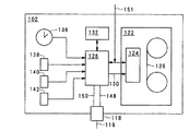
図2において、カメラ本体102は、磁気記録テープ126に関連して動作するリード/ライトヘッド124を備えたテープドライブ122を有している。また、図2において、カメラ本体は、接続チャネル130を介してテープドライブ122に接続されたメタデータ生成プロセッサ128を有している。メタデータ生成プロセッサ128には、データストレージ132と、クロック136と、3つのセンサ138、140、142も接続されている。また、図2に示すが、インターフェースユニット118は無線チャネル119を介してデータの送受信を行う。これに対応して、データの受信用と送信用の2つの接続チャネルが、対応する接続チャネル148、150を介してメタデータ生成プロセッサ128にインターフェースユニット118を接続する。図中、メタデータ生成プロセッサは、接続チャネル151を介して、カメラにより生成されるオーディオ/ビデオ信号を受信する。オーディオ/ビデオ信号は、テープドライブ122にも送られ、テープ126に記録される。
【0043】
図1に示すビデオカメラ101は、レンズ部104の視野に入るビジュアル情報を記録媒体に記録するように動作する。ビジュアル情報はカメラによりビデオ信号に変換される。マイク110により検出され、オーディオ信号としてビデオ信号とともに記録媒体に記録されるように構成された音声と合わせて、画像がビデオ信号として記録される。図2に示すように、記録媒体は磁気テープ126であり、リード/ライトヘッド124によりオーディオ及びビデオ信号を記録テープ126に記録するように構成されている。ビデオ信号及びオーディオ信号がリード/ライトヘッド124により磁気テープ126に記録される様子については、本発明の実施例を説明するものではないので、図2には示さず、詳細な説明も省略する。しかし、一旦、ユーザが画像を取り込んで、磁気テープ126を用いてこれらの画像をそれに伴うオーディオ信号とともに記録した場合、オーディオ/ビデオ信号のコンテンツを記述するメタデータを、PDA112を用いて入力してもよい。後述するように、このメタデータは、「テイク」等の所定のイベントに関連してオーディオ/ビデオ信号を識別する情報であってもよい。図2に示すように、インターフェースユニット118により、ユーザがPDA112を用いて付加したメタデータをカメラ本体102内に受信する手段が得られる。データ信号は、インターフェースユニット118にて無線チャネル119を介して受信することができる。インターフェースユニット118は、接続チャネル148、150を介してこれらのデータ信号を受信する取得プロセッサ128がこれらの信号を処理できるような形式に、これらの信号を変換する。
【0044】
メタデータは、接続チャネル151を介して受信されるオーディオ/ビデオ信号に関連して、メタデータ生成プロセッサ128により自動的に生成される。図2に示す実施例において、メタデータ生成プロセッサ128は、クロック136を参照してタイムコードを生成するとともに、テープ126上に、記録用に設けられたリニア記録トラックにてこれらのタイムコードを記録するように動作する。タイムコードは、メタデータ生成プロセッサ128によりクロック136から生成される。さらに、メタデータ生成プロセッサ128は、オーディオ/ビデオ信号を独自に識別するUMID等の他のメタデータを自動的に生成する。メタデータ生成プロセッサは、テープドライバ124と共動して、オーディオ/ビデオ信号とともにUMIDをテープに書き込む。
【0045】
他の実施例では、UMIDや他のメタデータをデータストレージ132に記憶し、テープ126から別個に通信する。この場合、メタデータ生成プロセッサ128によりテープIDが生成され、テープ126に書き込まれて、テープ126を他のテープと識別する。
【0046】
UMIDや、オーディオ/ビデオ信号のコンテンツを識別する他のメタデータを生成するため、メタデータ生成プロセッサ128は、クロック136の外にセンサ138、140、142からの信号を受信する動作を行うように構成されている。従って、メタデータ生成プロセッサは、これらの信号を統合するように動作し、カメラレンズ104の開口設定、シャッタースピード、取り込んだ画像が「グッドショット」であることを示すコントロールユニット108を介して受信した信号等のメタデータを、メタデータ生成プロセッサに供給する。これらの信号及びデータは、センサ138、140、142により生成され、メタデータ生成プロセッサ128にて受信される。本実施例のメタデータ生成プロセッサは、ビデオ信号の生成時にカメラにより用いられる動作パラメータを与えるシンタクティックメタデータを生成するように構成されている。さらに、メタデータ生成プロセッサ128は、カムコーダ101の状況、特に、オーディオ/ビデオ信号がテープドライブ124により記録されているか否かを監視する。レコードスタートが検出されると、インポイントタイムコードが取り込まれ、インポイントタイムコードに対応してUMIDが生成される。さらに、幾つかの実施例では拡張UMIDが生成されるが、この場合、メタデータ生成プロセッサは、オーディオ/ビデオ信号が取得された位置を表す空間座標を受信するように構成される。空間座標は、グローバル・ポジショニング・システム(GPS)に従って動作するレシーバにより生成される。レシーバは、カメラの外部にあってもよく、また、カメラ本体102に内蔵されてもよい。
【0047】
レコードスタートが検出されると、メタデータ生成プロセッサ128によりアウトポイントタイムコードが取り込まれる。上述のように、「グッドショット」マーカを生成することが可能である。「グッドショット」マーカは、記録プロセス中に生成され、メタデータ生成プロセッサにより検出される。「グッドショット」マーカは、対応するインポイント及びアウトポイントタイムコードとともに、テープに記憶されるか、あるいは、データストレージ132に記憶される。
【0048】
上述のように、PDA112は、カメラにより生成されるオーディオ/ビデオマテリアルの識別を容易にするのに用いられる。このため、PDAは、このオーディオ/ビデオマテリアルをシーン、ショット、テイク等の所定のイベントに関連付けるように構成されている。図1及び図2に示すカメラとPDAは、オーディオ/ビデオプロダクションのプランニング、取得、編集を行う総合システムの一部を構成する。プランニングにおいて、オーディオ/ビデオプロダクションを作成するのに必要なシーンが識別される。さらに、各シーン毎に、シーンを確立するのに必要なショット数が識別される。各ショットでは、多数のテイクが生成され、これらのテイクから所定数のテイクを用いて、最終的な編集のためのショットを生成する。従って、この形式のプランニング情報がプランニング段階で識別される。従って、プランニングされたシーン及びショットのそれぞれを表す又は識別するデータが、オーディオ/ビデオマテリアルを取り込むときにディレクターを支援するノートとともに、PDA112にロードされる。このようなデータの例を以下の表1に示す。
【0049】
【表1】

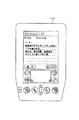
表1の第1列には、カメラにより取り込まれ、オーディオ/ビデオマテリアルを生成するイベントを示す。イベントは階層的に定められているが、各イベントには識別番号が設けられている。これに対応して、第2列には、プランニングされたショット又はシーンのコンテンツをディレクターに示す又は知らせるために、ノートが設けられている。例えば、第1行では、オーディオ/ビデオプロダクションを、BMWによるローバーの売却を報道するニュースストーリーとして識別している。表1に示すプランニング情報の抜粋では、それぞれ独自の識別番号が設けられた3つのシーンがある。これらのシーンは、それぞれ「ロングブリッジの外」、「BMWミュンヘン本部」、「大臣のインタビュー」である。これに対応して各シーン毎に多数のショットが識別されており、これらのショットは、独自のショット識別番号を有して各シーンの下に示されている。また、これら各ショットのコンテンツに対応するノートが第2列に記載されている。従って、例えば第1シーン「ロングブリッジの外」について、3つのショットが識別されている。これらは「ロングブリッジBMW」、「シフトを離れる労働者」、「駐車場の労働者」である。この情報をPDAにロードして、ディレクター又はカメラマンひとりで、ニュースストーリーを撮影すべき場所にPDAを携帯し、プランニングしたオーディオ/ビデオマテリアルを収集することができる。この情報を表示するグラフィカルユーザインターフェースを備えたPDAの外観を図3に示す。
【0051】
図1に示すように、PDA112はカメラ101とデータの通信を行うように構成されている。このため、メタデータ生成プロセッサ128は、インターフェース118を介してPDA112とデータの通信を行うように構成されている。インターフェース118は、例えば、既知の規格に従って無線通信を行う赤外線リンク119であってもよい。図2に示すPDAとメタデータ生成に関連するカメラ構成部分を図4に詳細に示す。
【0052】
図4において、メタデータの生成及びPDA112との通信に関連するカメラ構成部分を別個の取得ユニット152として示す。なお、取得ユニット152はカメラ102に内蔵することもできる。取得ユニット152は、メタデータ生成プロセッサ128とデータストレージ132を備えている。また、説明の都合上図4には示していないが、取得ユニット152は、クロック136とセンサ138、140、142も備えている。あるいは、図2に示すこれらの特徴の幾つか又はすべてをカメラ102に内蔵し、タイムコード等のメタデータやオーディオ/ビデオ信号自体を定めるのに必要な信号を、インターフェースポート154に接続された通信リンク153を介して通信してもよい。従って、メタデータ生成プロセッサ128は、タイムコードやオーディオ/ビデオマテリアルにも、オーディオ/ビデオマテリアルの生成に用いる他のパラメータにもアクセスが得られる。オーディオ/ビデオ信号だけでなくタイムコードやパラメータも表す信号が、インターフェースチャネル156を介してインターフェースポート154から受信される。また、取得ユニット152には、スクリーンドライバ158により駆動される画面(図示せず)が設けられている。また、図4では、接続チャネル162を介してメタデータ生成プロセッサ128に接続されている通信プロセッサ160が、取得ユニットに設けられている。通信プロセッサ160により、アンテナ164を用いた無線周波数通信チャネルを介して通信が行われる。取得ユニット152の外観を図5に示す。
【0053】
図4にはPDA112も示されている。PDA112には、赤外線リンク119を介して取得ユニット152との間で通信を行うための赤外線通信ポート165が対応して設けられている。PDA112内のデータプロセッサ166は、接続チャネル166を介して赤外線ポート165との間でデータの通信を行うように構成されている。また、PDA112には、データストレージ167と、データプロセッサ166に接続されたスクリーンドライバ168とが設けられている。
【0054】
図3に示すPDA112と図5に示す取得ユニットにより、本発明の一実施例の図示が得られる。PDA112と取得ユニット152の配置及び接続を示す概略図を図6に示す。図6に示す例では、取得ユニット152はカメラ101の背面に装着され、6ピンリモートコネクタによりカメラに接続されるとともに、記録テープに記録されたタイムコードを表す外部信号を伝える接続チャネルに接続されている。従って、矢印と線で示される6ピンリモートコネクタとタイムコードは、図4に示す通信チャネル153を構成する。図6において、インターフェースポート154は、RM−P9/LTC−RS422コンバータ154からなるVA−DN1コンバータであるとする。RM−P9はカメラリモートコントロールプロトコルであり、LTCはアナログ信号形式でのリニアタイムコードである。これは、インターフェースポート154の一部を構成する接続チャネルを介してRS422−RS232コンバータ154”と通信を行うように構成されている。コンバータ154”は、RS232規格に従って動作する接続チャネル156を介してメタデータ生成プロセッサ128と通信を行う。
【0055】
図4に戻り、所定のプロダクション情報がロードされたPDA112は、赤外線リンク119を介して次ショットID番号を送ることにより、オーディオ/ビデオマテリアルを生成する現シーン及びショットを送るように構成されている。その所定の情報を、別個のリンク又は赤外線通信リンク119を介して、取得ユニット152に送ってデータストレージ132に記憶しておいてもよい。しかし、実際は、取得ユニット152は、現在取り込まれているシーン又はショットID番号に関連してメタデータを生成するように指示されている。現ショットの情報を受信した後、カメラ102は「ショットのテイク」をとるように動作する。テイクのオーディオ/ビデオマテリアルは、対応するタイムコードとともに記録テープ126に記録される。これらのタイムコードは、インターフェースポート154を介してメタデータ生成プロセッサ128にて、オーディオ/ビデオマテリアルとともに受信される。現在取り込まれている所定の現ショットを知らされたメタデータ生成プロセッサ128は、そのショットの各テイク毎のタイムコードのログを行う。従って、メタデータ生成プロセッサは、各テイクのイン及びアウトタイムコードのログを行い、これらをデータストレージ132に記憶する。
【0056】
メタデータ生成プロセッサ128により生成及びログが行われた情報を以下の表2に示す。第1列において、シーン及びショットがそれぞれ対応するID番号により識別され、各ショット毎に階層的に示された幾つかのテイクがカメラ操作者により作成される。従って、PDA112から現ショットの情報を受信した後、カメラ操作者が作成した各テイクがメタデータ生成プロセッサ128によりログされ、このテイクについてのイン及びアウトポイントを第2及び第3列に示すとともにデータストレージ132に記憶する。この情報は、図5に示すように、取得ユニット152の画面に表示してもよい。さらに、上述のように、メタデータ生成プロセッサ128は、各テイクの間に生成されるオーディオ/ビデオマテリアルについて各テイク毎のUMIDを生成する。各テイク毎のUMIDは表2の第4列を構成する。また、幾つかの実施例において、マテリアルを記録するテープの独自のIDを与えるため、テープIDを生成してメタデータに関連付けている。テープIDはテープに書き込んでもよく、また、ビデオテープカセット本体に内蔵されているランダムアクセスメモリチップに記憶してもよい。このランダムアクセスメモリチップは、テープID番号を遠隔的に読み出す手段を与えるTELEFILE(RTM)システムとして知られている。テープIDは磁気テープ126に書き込まれて、このテープを独自に識別する。好ましい実施例において、TELEFILE(RTM)システムには、メモリの一部として製造され、テープID番号として使用することができる独自の番号が設けられている。他の実施例では、TELEFILE(RTM)システムにより、記録されたオーディオ/ビデオマテリアルアイテムのイン/アウトタイムコードが自動的に得られる。
【0057】
一実施例において、以下の表2に示す情報は、別個の記録チャネルにある磁気テープに記録されるように構成されている。しかし、他の実施例では、表2に示すメタデータは、通信プロセッサ160又は赤外線リンク119のいずれかを用いてテープ126から別個に通信される。メタデータをPDA112で受信して分析してもよく、また、PDAによりメタデータの通信をさらにおこなってもよい。
【0058】
【表2】
通信プロセッサ160は、無線通信リンクを介して、メタデータ生成プロセッサ128により生成されたメタデータを送信する動作を行うように構成することができる。メタデータは、遠隔位置にあるスタジオにより無線通信リンクを介して受信され、このスタジオではメタデータを取得するとともに、磁気テープ126に記録されたオーディオ/ビデオマテリアルより先にこのメタデータの処理を行うことができる。これにより、マテリアルの編集を行うポストプロダクションにおいてオーディオ/ビデオプロダクションを生成するレートを改善できるという利点が得られる。
【0060】
本発明の実施例により得られるさらなる利点としては、記録されたオーディオ/ビデオ信号内のある時間位置にピクチャスタンプが生成されるように構成することである。ピクチャスタンプは、画像のデジタル表示であるとして当該分野の技術者に知られているものであり、本実施例では、カメラにより得られた動画ビデオマテリアルから生成される。ピクチャスタンプは、ビデオ信号から画像を表すのに必要なデータ量を低減するため、低画質のものであってもよい。従って、ピクチャスタンプを圧縮符号化して、画質を低下させてもよい。しかし、ピクチャスタンプはオーディオ/ビデオマテリアルのコンテンツのビジュアルインディケーションを与えるので、メタデータの重要なアイテムである。従って、例えば特定のテイクのイン及びアウトタイムコードにて、ピクチャスタンプを生成してもよい。これにより、メタデータ生成プロセッサ128により生成され、データストレージ132に記憶されたメタデータと、ピクチャスタンプを関連付けることができる。従って、ピクチャスタンプは、例えば、ピクチャスタンプにより表される画像を記録するテープ上の位置を識別するタイムコード等のメタデータのアイテムに関連付けられる。ピクチャスタンプは、「グッドショット」マーカを付して生成してもよい。ピクチャスタンプは、メタデータ生成プロセッサ128により、通信リンク153を介して受信したオーディオ/ビデオ信号から生成される。従って、メタデータ生成プロセッサは、ピクチャスタンプを生成するため、データサンプリング及び圧縮符号化プロセスを行うように動作する。ピクチャスタンプが生成されると、これらは幾つかの用途に使用することができる。ピクチャスタンプをデータファイルに記憶して、テープ126から別個に通信してもよく、あるいは、別個の記録チャネルにより圧縮形式でテープ126に記憶してもよい。また、好ましい実施例において、通信プロセッサ160を用いて、プロデューサがピクチャスタンプを分析する遠隔位置のスタジオにピクチャスタンプを送ってもよい。これにより、カメラ操作者により生成されるオーディオ/ビデオマテリアルが必要に応じたものであるか否かについてのインディケーションが、プロデューサに与えられる。
【0061】
さらに他の実施例において、ピクチャスタンプはPDA112に送られ、PDAの画面に表示される。これは赤外線ポート119を介して行うことができるが、通信プロセッサ160との通信を行うことができる他の無線リンクをPDAに設けてもよい。このように、ハンドヘルドPDA112を有するディレクターには、カメラにより生成された現オーディオ/ビデオコンテンツを示すインディケーションが与えられる。これにより、現在生成されているオーディオ/ビデオマテリアルのアーティストや芸術的な質を示すインディケーションがすぐに得られる。上述のように、ピクチャスタンプは圧縮符号化されているので、PDAに高速で通信することができる。
【0062】
図4に示す取得ユニット152のさらなる利点としては、オーディオ/ビデオマテリアルの受信前に、そのマテリアルのコンテンツを示すインディケーションを遠隔位置にあるスタジオの編集者に与えることにより、編集プロセスを効率化することである。これは、無線リンクを介してピクチャスタンプがメタデータとともに通信されて、オーディオ/ビデオマテリアル自体を受信する前にオーディオ/ビデオマテリアルのコンテンツを示すインディケーションが編集者に与えられるからである。このように、オーディオ/ビデオマテリアルの帯域幅が広いまま保つことが可能であり、これに対応して高品質が得られるとともに、メタデータとピクチャスタンプは比較的狭い帯域幅で、比較的低い品質の情報となる。帯域幅が狭いため、メタデータとピクチャスタンプは、かなり狭い帯域幅のチャネルで無線リンクを介して通信することができる。これにより、オーディオ/ビデオマテリアルのコンテンツを記述するメタデータを高速で通信することができる。
【0063】
メタデータ生成プロセッサ128により生成されたピクチャスタンプは、記録されたオーディオ/ビデオマテリアル中のいずれの位置にあってもよい。一実施例では、ピクチャスタンプが各テイクのイン及びアウトポイントにて生成される。しかし、本発明の他の実施例では、アクティビティプロセッサ170がビデオマテリアル内の相対アクティビティを検出するように構成される。これは、ビデオ信号により表される画像の色成分のヒストグラムをコンパイルして、色成分の変化率を決定し、これら色成分の変化を用いて画像内のアクティビティを示すというプロセスを行うことにより行われる。また、これに代えて、あるいは、これに加えて、画像内の動きベクトルを用いてアクティビティを示す。そして、アクティビティプロセッサ170は、ビデオマテリアル内の相対アクティビティを示す信号を生成するように動作する。メタデータ生成プロセッサ128は、ビデオ信号により表される画像内のアクティビティが大きいほど多くのピクチャスタンプを生成するように、アクティビティ信号に応じてピクチャスタンプを生成する。
【0064】
本発明の他の実施例において、アクティビティプロセッサ170は、接続チャネル172を介してオーディオ信号を受信し、そのオーディオ信号内の音声を認識するように構成されている。そして、アクティビティプロセッサ170は、この音声のコンテンツを表すコンテンツデータをテキストとして生成する。テキストデータは、データプロセッサ128に送られてデータストレージ132に記憶されるか、あるいは、ピクチャスタンプについて既に説明したのと同様にして通信プロセッサ160を介して他のメタデータとともに送られる。
【0065】
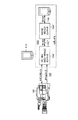
図7に、オーディオ/ビデオマテリアルを編集して、オーディオ/ビデオプログラムを作成するポストプロダクションプロセスを概略的に示す。図7に示すように、ピクチャスタンプ及び/又は音声コンテンツ情報が含むメタデータは、破線174で表す別個のルートを介して取得ユニット152からメタデータデータベース176に送られる。ルート174は、例えばUMTS、GSM等により構成される無線通信リンクを表す。
【0066】
データベース176は、メタデータをオーディオ/ビデオマテリアルと関連付けて記憶する。高品質形式のオーディオ/ビデオマテリアルはテープ126に記録される。従って、テープ126は編集場所に戻されて、取り込みプロセッサ178により取り込まれる。テープ126に記録されたテープID、又は、オーディオ/ビデオマテリアルのコンテンツを示すインディケーションを与える他のメタデータを用いて、破線180で示すように、データストレージ176に記憶されたメタデータをテープ上のオーディオ/ビデオマテリアルと関連付ける。
【0067】
本発明の実施例ではオーディオ/ビデオ信号を記憶するための記録媒体としてビデオテープを用いているが、磁気ディスクやランダムアクセスメモリ等、他の記録媒体を用いてもよい。
【0068】
取り込みプロセッサ
図7は、オーディオ/ビデオマテリアルを編集して、オーディオ/ビデオプログラムを作成するポストプロダクションプロセスを概略的に示す。図7に示すように、ピクチャスタンプ及び/又は音声コンテンツ情報が含むメタデータは、破線174で表す別個のルートを介して取得ユニット152からメタデータデータベース176に送られる。ルート174は、例えばUMTS、GSM等により構成される無線通信リンクを表す。
【0069】
データベース176は、メタデータをオーディオ/ビデオマテリアルと関連付けて記憶する。高品質形式のオーディオ/ビデオマテリアルはテープ126に記録される。従って、テープ126は編集場所に戻されて、取り込みプロセッサ178により取り込まれる。テープ126に記録されたテープID、又は、オーディオ/ビデオマテリアルのコンテンツを示すインディケーションを与える他のメタデータを用いて、破線180で示すように、データストレージ176に記憶されたメタデータをテープ上のオーディオ/ビデオマテリアルと関連付ける。
【0070】
図7において、取り込みプロセッサ178は、接続線182で表す通信チャネルにより形成されるネットワークに接続されている。接続線182は、相互接続されたネットワークを形成する機器にデータ通信を行うための通信チャネルを表している。このため、これらの機器には、イーサネット、RS422等の既知のアクセス技術に従って動作するネットワークカードが設けられている。さらに、後述するように、通信ネットワーク182は、シリアルデジタルインターフェース(SDI)又はシリアルデジタルトランスポートインターフェース(SDTI)に従ってデータ通信を行ってもよい。
【0071】
また、通信ネットワーク182には、メタデータデータベース176と、オーディオ/ビデオマテリアルを取り込むオーディオ/ビデオサーバ190も接続されている。さらに、編集端末184、186もデジタルマルチ効果プロセッサ188とともに通信チャネル182に接続されている。
【0072】
通信チャネル182により、取り込みプロセッサ178にロードされたテープ、ディスク又は他の記録媒体上にあるオーディオ/ビデオマテリアルへのアクセスが得られる。
【0073】
メタデータデータベース176は、取り込みプロセッサ178にロードされた記録媒体に記録されたオーディオ/ビデオマテリアルのコンテンツを記述するメタデータを、ルート174を介して受信するように構成されている。
【0074】
なお、実施例ではオーディオ/ビデオ信号を記憶する記録媒体としてビデオテープを用いたが、磁気ディスクやランダムアクセスメモリ等の他の記録媒体を用いてよく、ビデオテープは単なる一例に過ぎない。
【0075】
編集端末184、186及びデジタルマルチ効果プロセッサ188には、取り込みプロセッサ178にロードされたテープに記録されてオーディオ/ビデオマテリアルと、通信ネットワーク182を介してメタデータデータベース176に記憶されたオーディオ/ビデオマテリアルを記述するメタデータへのアクセスが得られる。メタデータデータベース176を伴う取り込みプロセッサ178の動作について以下に詳細に説明する。
【0076】
図8は、取り込みプロセッサ178の例を示す。図8において、取り込みプロセッサ178は、取り込みプロセッサ178の一部を構成するビデオテープ記録/再生部にロードされたテープに記録されたオーディオ/ビデオマテリアルをナビゲートするためのジョグシャトルコントロール200を有している。また、取り込みプロセッサ178は、オーディオ/ビデオマテリアルの選択部分を記述するピクチャスタンプを表示するように構成された表示画面202を有している。表示画面202は、タッチによりオーディオ/ビデオマテリアルを選択するための手段をユーザに与えるタッチ画面として動作する。また、取り込みプロセッサ178は、スクリプト、カメラの種類、レンズの種類、UMIDを含む全種類のメタデータを画面202に表示するように構成されている。
【0077】
図9に示すように、取り込みプロセッサ178は、オーディオ/ビデオマテリアルが記録されたビデオテープを並行してロードすることができる複数のビデオテープ記録/再生部を備えてもよい。図9に示す例では、RS422リンクとSDIイン/アウトリンクを介して、ビデオテープレコーダ204が取り込みプロセッサ178に接続されている。従って、取り込みプロセッサ178は、ビデオテープレコーダにロードされたビデオテープからオーディオ/ビデオマテリアルを再生するために、ビデオテープレコーダ204のいずれかにアクセスすることができるデータプロセッサとなる。さらに、取り込みプロセッサ178には、通信ネットワーク182にアクセスするためにネットワークカードが設けられている。しかし、図9からわかるように、通信チャネル182は、比較的狭い帯域幅のデータ通信チャネル182’と、ビデオデータを送るための広い帯域幅のSDIチャネル182”とにより構成されている。これに対応して、取り込みプロセッサ178は、対応するオーディオ/ビデオマテリアルアイテムのリクエストを送るために、RS422リンクを介してビデオテープレコーダ204に接続されている。これらのオーディオ/ビデオマテリアルアイテムを要求すると、SDIネットワークを介した配信のためのSDI通信リンク206を介して、オーディオ/ビデオマテリアルが取り込みプロセッサ178に返信される。このリクエストは、例えば、オーディオ/ビデオマテリアルアイテムを独自に識別するUMIDを有していてもよい。
【0078】
メタデータデータベース176に関連した取り込みプロセッサの動作について、図10を参照して以下に説明する。図10において、メタデータデータベース176は、特定のテープID212に関連する多数アイテムのメタデータ210を有している。矢印214を付した破線で示すように、テープID212は、メタデータ210に対応するオーディオ/ビデオマテリアルが記録された特定のビデオテープ216を識別する。図10に示す実施例では、テープID212がビデオテープ218のリニアタイムコードエリア220に書き込まれる。しかし、他の実施例からわかるように、テープIDを垂直ブランキング部等、他の位置に書き込むこともできる。ビデオテープ216は、取り込みプロセッサ178の一部を構成するビデオテープレコーダ204のうちのいずれか1つのロードされる。
【0079】
動作時には、編集端末184のいずれか1つが、狭い帯域幅の通信チャネル182’を介してメタデータデータベース176にアクセスするように構成されるので、その編集端末184には、テープ216に記録されたオーディオ/ビデオマテリアルのコンテンツを記述するメタデータ210へのアクセスが得られる。メタデータ210には、著作権者「BSkyB」、画像の解像度、ビデオマテリアルの符号化形式、プログラムの名称(この場合、「グランドスタンド(特別観覧席)」)等の情報と、日時や観衆等の情報が含まれる。さらに、メタデータにはオーディオ/ビデオマテリアルのコンテンツのノートが含まれる。
【0080】
オーディオ/ビデオマテリアルの各アイテムは、オーディオ/ビデオマテリアルを識別するUMIDと関連している。このため、編集端末184を用いて、プログラム作成に必要なオーディオ/ビデオマテリアルアイテムをメタデータ210から識別及び選択することができる。このマテリアルは、マテリアルに関連するUMIDにより識別される。オーディオ/ビデオマテリアルにアクセスして、プログラムを作成するため、編集端末184は狭い帯域幅の通信ネットワーク182を介して、このマテリアルのリクエストを送る。リクエストには、オーディオ/ビデオマテリアルアイテムを識別するUMIDが含まれる。編集端末184から受信したオーディオ/ビデオマテリアルのリクエストに応じて、取り込みプロセッサ178は、ビデオカセット216がロードされているビデオテープレコーダから、UMIDにより識別されるオーディオ/ビデオマテリアルアイテムを選択的に再生するように構成されている。そして、このオーディオ/ビデオマテリアルは、SDIネットワーク182”を介して編集端末184に返信され、編集中のオーディオ/ビデオプロダクションに組み込まれる。送られたオーディオ/ビデオマテリアルはオーディオ/ビデオサーバ190に取り込まれ、ここでオーディオ/ビデオの記憶及び再生を行うことができる。
【0081】
図11は、メタデータ210をオーディオ/ビデオマテリアルとともに好適な記録媒体に記録する他の構成を示す。例えば、ビデオテープ218’のオーディオトラックのいずれか1つにメタデータ210を記録することもできる。また、記録媒体として、ランダムアクセスを可能にするとともに大容量のデータ記憶を行うことができる光ディスク又は磁気ディスクを用いてもよい。この場合、メタデータ210をオーディオ/ビデオマテリアルとともに記憶してもよい。
【0082】
さらに他の構成では、メタデータの幾つか又はすべてをテープ216に記録する。これは例えばテープ218のリニア記録トラックに記録することができる。テープに記録されたメタデータに関する幾つかのメタデータは、データベース176に別個に送って記憶してもよい。メタデータを取り込むにはさらにステップが必要となるが、このため、取り込みプロセッサ178は、記録媒体218’からメタデータを読み出して、通信ネットワーク182’を介してメタデータをデータベース176に送るように構成されている。従って、取り込みプロセッサ178により取り込まれるオーディオ/ビデオマテリアルに関連するメタデータは、別の媒体を介して、あるいは、オーディオ/ビデオマテリアルも記録されている記録媒体を介して、データベース176に取り込まれることがわかる。
【0083】
また、オーディオ/ビデオマテリアルに関連するメタデータには、ビデオマテリアル中の様々な位置における画像を低画質で表示するピクチャスタンプを含んでもよい。これらは取り込みプロセッサ178のタッチ画面202にて提示することができる。さらに、これらのピクチャスタンプを、ネットワーク182’を介して編集端末184、186又は効果プロセッサ188に送り、オーディオ/ビデオマテリアルのコンテンツを示すインディケーションを与えてもよい。従って、編集者にはオーディオ/ビデオマテリアルの画像表示が与えられ、ここから、オーディオ/ビデオマテリアルアイテムの選択を行うことができる。さらに、ピクチャスタンプをメタデータ210の一部としてデータベース176に記憶してもよい。従って、編集者は、ピクチャスタンプに関連するUMIDを用いて、対応するピクチャスタンプについて選択したアイテムを取り出すことができる。
【0084】
本発明の他の実施例において、記録媒体はオーディオ/ビデオマテリアルとともに記録されたピクチャスタンプを記録するのに十分な容量を有していないことがある。これは、記録媒体がビデオテープ216である場合に起こりやすい。この場合、必ずしもというわけではないが、オーディオ/ビデオマテリアルの取り込み前又は取り込み中にピクチャスタンプを生成することが特に好適である。
【0085】
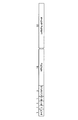
図7に戻り、他の実施例において、取り込みプロセッサ178はプリプロセッサユニットを備えてもよい。取り込みプロセッサ178に内蔵されたプリプロセッサユニットは、本例ではビデオテープ126である記録媒体に記録されたオーディオ/ビデオマテリアルを受信するように構成されている。このため、プリプロセッサユニットは別個のビデオ記録/再生部を設けてもよく、あるいは、取り込みプロセッサ178の一部を構成するビデオテープ記録/再生部と組み合わせてもよい。プリプロセッサユニットは、オーディオ/ビデオマテリアルに関連するピクチャスタンプを生成する。上述のように、ピクチャスタンプは、オーディオ/ビデオマテリアルアイテムのコンテンツを画像表示するのに用いられる。しかし、本発明のさらに他の実施例によれば、プリプロセッサユニットは、オーディオ/ビデオマテリアルの処理を行うとともに、オーディオ/ビデオマテリアルのコンテンツにおける相対アクティビティを表すアクティビティインディケータを生成するように動作する。これは、例えば、ビデオ信号で表される画像内の色成分のヒストグラムに応じてアクティビティ信号を生成するとともに、カラーヒストグラム成分の変化率に応じてアクティビティ信号を生成するように動作するプロセッサを用いて行うことができる。そして、プリプロセッサユニットは、ビデオマテリアル中の、アクティビティ信号が示すアクティビティ期間がある位置にて、ピクチャスタンプを生成するように動作する。これを図12に示す。図12Aにおいて、ビデオ信号における時間を表すライン226に沿ってピクチャスタンプ224が生成される。図12Aに示すように、ピクチャスタンプ224は、タイムライン226に沿った、矢印228として表されるアクティビティ信号がアクティビティイベントを示す時点に生成される。これは、例えば、カメラの視野に誰かが出入りして、ビデオ信号が表す動きが大きい場合である。このため、アクティビティ信号は、例えば、MPEG規格に応じて生成された動きベクトルである動きベクトルを用いて生成することができる。
【0086】
本発明の他の実施例において、プリプロセッサは、テープ126に記憶されたオーディオ/ビデオマテリアルアイテムの一部を構成するオーディオ信号内の音声に対応するテキスト情報を生成する。テキスト情報は、ピクチャスタンプの代わりに又はピクチャスタンプに加えて生成してもよい。この場合、テキストは、例えばセンテンスの最初の数語及び/又は話し手の最初のアクティビティについて生成される。これはオーディオ/ビデオマテリアルの一部を記録又は構成するテープ上のオーディオ信号から検出される。テキストが生成される開始点を矢印230としてタイムライン226に沿って表す。また、テキストは、センテンスの終わり又は音声における他の重要点にて生成することもできる。
【0087】
検出された音声の開始点で、音声プロセッサは音声のコンテンツのテキスト表記を生成する。このため、図12Bに示すタイムライン226には、音声のアクティビティ期間の開始点に、音声のコンテンツに対応するテキスト232がある。
【0088】
プリプロセッサにより生成されたピクチャスタンプと音声アクティビティのテキスト表記は、通信チャネル182を介してメタデータデータベース176に送られて記憶される。ピクチャスタンプとテキストは、ピクチャスタンプ224とテキスト情報232が生成された対応するオーディオ/ビデオマテリアルアイテムを識別するUMIDと関連付けて記憶される。これにより、編集端末184、186のいずれか一方を操作する編集者には、取り込みプロセッサ178を用いてオーディオ/ビデオマテリアルを取り込む前にオーディオ/ビデオマテリアルのコンテンツを分析する手段が与えられる。この場合、ビデオテープ126は取り込みプロセッサ178にロードされ、その後、ネットワーク通信チャネル182を介してオーディオ/ビデオマテリアルにアクセスすることができる。従って、編集者には、オーディオ/ビデオマテリアルのコンテンツを示すインディケーションが迅速に与えられるので、編集者が必要とする特定のマテリアルアイテムに適切なマテリアル部分のみを取り込むことができる。これにより、編集者によるオーディオ/ビデオプロダクションの作成の効率が改善されるという利点が得られる。
【0089】
他の実施例において、プリプロセッサは別ユニットとすることができ、ピクチャスタンプ及び/又はテキスト情報を表示する画面と、取り込むべきオーディオ/ビデオマテリアルアイテムを選択する手段を与えるタッチ画面等の手段とが設けられる。
【0090】
本発明のさらに他の実施例において、取り込みプロセッサ178は、オーディオ/ビデオマテリアルが取り込まれている間にUMID等のメタデータアイテムを生成する。これは、カメラ152の取得ユニットがUMIDを生成するようには構成されてなく、ユニークマテリアルリファレンスナンバー(MURN)を生成するので、必要である。MURNはテイク等の各マテリアルアイテム毎に生成される。MURNは、UMIDよりもかなり短くなるように構成されるので、ビデオテープのリニアタイムコード内に収容することができる。UMIDの場合、大きいのでリニアタイムコードに収容することは困難である。また、MURNをテープのTELEFILE(RTM)ラベルに書き込むこともできる。MURNにより、テープ上のオーディオ/ビデオマテリアルアイテムのユニークIDが得られる。MURNは、線174で示すように、データベース176に別個に送ることができる。
【0091】
取り込みプロセッサ178では、マテリアルアイテムについてのMURNをテープ又はTELEFILEラベルから再生する。各MURN毎に、取り込みプロセッサ178はMURNに対応するUMIDを生成するように動作する。そして、UMIDは、MURNとともにデータベース176に送られて、データベース176内に既に存在するMURNに関連付けられてデータベースに取り込まれる。
【0092】
カメラメタデータ
以下、プログラムの作成中に生成することが可能なメタデータの種類と、そのメタデータを構成するのに可能な構成アプローチについて、例を用いて説明する。
【0093】
図13は、メタデータを構成するための構造例を示す。メタデータをそれぞれ有する多数のフィールドからなる多数のテーブルが設けられている。これらのテーブルは、各テーブル内の共通のフィールドにより互いに関連付けられることにより、リレーショナル構造を得ることができる。また、この構造は、テーブルが表すオブジェクトの多数のインスタンスを表すために、同じテーブルの多数のインスタンスを有してもよい。フィールドは所定の方法でフォーマットされる。フィールドのサイズも所定のものとすることができる。サイズの例としては、2バイトを表す「Int」、4バイトを表す「LongInt」、8バイトを表す「Double」がある。また、フィールドのサイズを、例えば8、10、16、32、128、255文字等、フィールド内に保持する文字数を参照して定めることもできる。
【0094】
この構造について詳細に説明すると、プログラムテーブルがある。プログラムテーブルは、プログラムID(PID)、タイトル、ワーキングタイトル、ジャンルID、一覧、アスペクト比、ディレクターID、ピクチャスタンプを含む多数のフィールドを有している。プログラムテーブルに関連して、ジャンルテーブル、キーワードテーブル、スクリプトテーブル、ピープルテーブル、スケジュールテーブル、及び、複数のメディアオブジェクトテーブルがある。
【0095】
ジャンルテーブルは、プログラムテーブルのジャンルIDフィールドと関連付けられたジャンルIDと、ジャンルディスクリプションとを含む多数のフィールドを有している。
【0096】
キーワードテーブルは、プログラムテーブルのプログラムIDフィールドと関連付けられたプログラムIDと、キーワードIDと、キーワードとを含む多数のフィールドを有している。
【0097】
スクリプトテーブルは、スクリプトID、スクリプト名、スクリプトタイプ、ドキュメントフォーマット、パス、作成日、原作者、バージョン、最終変更日、変更者、プログラムIDに関連付けられたPID、ノートと含む多数のフィールドを有している。ピープルテーブルは、イメージを含む多数のフィールドを有している。
【0098】
ピープルテーブルは、多数の個別テーブルと多数のグループテーブルに関連付けられている。各個別テーブルは、イメージを含む多数のフィールドを有している。各グループテーブルは、イメージを含む多数のフィールドを有している。各個別テーブルは、プロダクションスタッフテーブル又はキャストテーブルのいずれかと関連付けられている。
【0099】
プロダクションスタッフテーブルは、プロダクションスタッフID、姓、ファーストネーム、契約ID、エージェント、エージェンシーID、Eメール、住所、電話番号、役割ID、ノート、アレルギー、誕生日、国民保険番号、バンクID、ピクチャスタンプを含む多数のフィールドを有している。
【0100】
キャストテーブルは、キャストID、姓、ファーストネーム、役名、契約ID、エージェント、エージェンシーID、エクイティ番号、Eメール、住所、電話番号、誕生日、バンクID、ピクチャスタンプを含む多数のフィールドを有している。プロダクションスタッフテーブルとキャストテーブルに関連して、バンクディテールテーブルとエージェンシーテーブルがある。
【0101】
バンクディテールテーブルは、プロダクションスタッフテーブルのバンクIDフィールドとキャストテーブルのバンクIDフィールドに関連付けられたバンクID、ソートコード、口座番号、口座名を含む多数のフィールドを有している。
【0102】
エージェンシーテーブルは、プロダクションスタッフテーブルのエージェンシーIDフィールドとキャストテーブルのエージェンシーIDフィールドに関連付けられたエージェンシーID、名称、所在地、電話番号、ウェブサイト及びEメール、ピクチャスタンプを含む多数のフィールドを有している。また、プロダクションスタッフテーブルに関連して役割テーブルがある。
【0103】
役割テーブルは、プロダクションスタッフテーブルの役割IDフィールドに関連付けられた役割ID、職務、ノート、ピクチャスタンプを含む多数のフィールドを有している。各グループテーブルは、団体テーブルと関連付けられている。
【0104】
団体テーブルは、団体ID、名称、種類、所在地、契約ID、連絡先名、連絡先電話番号、ウェブサイト、ピクチャスタンプを含む多数のフィールドを有している。
【0105】
各メディアオブジェクトテーブルは、メディアオブジェクトID、名称、ディスクリプション、ピクチャスタンプ、PID、フォーマット、スケジュールID、スクリプトID、マスタIDを含む多数のフィールドを有している。各メディアオブジェクトテーブルに関連して、ピープルテーブル、マスタテーブル、スケジュールテーブル、ストーリーボードテーブル、スクリプトテーブル、及び多数のショットテーブルがある。
【0106】
マスタテーブルは、メディアオブジェクトテーブルのマスタIDフィールドに関連付けられたマスタID、タイトル、ベーシックUMID、EDL ID、テープID、継続時間、ピクチャスタンプを含む多数のフィールドを有している。
【0107】
スケジュールテーブルは、スケジュールID、スケジュール名、ドキュメントフォーマット、パス、作成日、原作者、開始日、終了日、バージョン、最終変更日、変更者、ノート、プログラムIDに関連付けられたPIDを含む多数のフィールドを有している。
【0108】
契約テーブルは、プロダクションスタッフテーブルとキャストテーブルと団体テーブルの契約IDに関連付けられた契約ID、開始日、レート、ジョブタイトル、満了日、詳細を含んでいる。
【0109】
ストーリーボードテーブルは、ショットテーブルのストーリーボードに関連付けられたストーリーボードID、ディスクリプション、著者、パス、メディアIDを含む多数のフィールドを有している。
【0110】
各ショットテーブルは、ショットID、PID、メディアID、タイトル、ロケーションID、ノート、ピクチャスタンプ、スクリプトID、スケジュールID、ディスクリプションを含む多数のフィールドを有している。各ショットテーブルに関連して、ピープルテーブル、スケジュールテーブル、スクリプトテーブル、ロケーションテーブル、及び、多数のテイクテーブルがある。
【0111】
ロケーションテーブルは、ショットテーブルのロケーションIDフィールドに関連付けられたロケーションID、GPS、所在地、ディスクリプション、名称、1時間毎の費用、ディレクション、連絡先名、連絡先住所、連絡先電話番号、ピクチャスタンプを含む多数のフィールドを有している。
【0112】
各テイクテーブルは、ベーシックUMID、テイク番号、ショットID、メディアID、タイムコード・イン、タイムコード・アウト、サインメタデータ、テープID、カメラID、ヘッド時間、ビデオグラファ、インスタンプ、アウトスタンプ、レンズID、オートID、取り込みID、ノートを含む多数のフィールドを有している。各テイクテーブルに関連して、テープテーブル、タスクテーブル、カメラテーブル、レンズテーブル、取り込みテーブル、及び、多数のテイクアノテーションテーブルがある。
【0113】
取り込みテーブルは、テイクテーブルにおける取り込みIDに関連付けられた取り込みIDと、ディスクリプションとを含んでいる。
【0114】
テープテーブルは、テイクテーブルのテープIDフィールドに関連付けられたテープID、PID、フォーマット、最大継続時間、第1用途、最大削除、現削除、ETA(予測到着時刻)、最終削除日、ピクチャスタンプを含む多数のフィールドを有している。
【0115】
タスクテーブルは、タスクID、PID、テイクテーブルのメディアID及びショットIDフィールドに関連付けられたメディアID及びショットID、タイトル、タスクノート、分配リスト、CCリストを含む多数のフィールドを有している。タスクテーブルに関連して、プランドショットテーブルがある。
【0116】
プランドショットテーブルは、プランドショットID、タスクテーブルのPID、メディアID、ショットIDにそれぞれ関連付けられたPID、メディアID、ショットID、ディレクター、ショットタイトル、ロケーション、ノート、ディスクリプション、ビデオグラファ、期日、プログラムタイトル、メディアタイトル、アスペクト比、フォーマットを含む多数のフィールドを有している。
【0117】
カメラテーブルは、テイクテーブルのカメラIDフィールドに関連付けられたカメラID、製造者、モデル、フォーマット、シリアル番号、ヘッド時間、レンズID、ノート、連絡先名、連絡先住所、連絡先電話番号、ピクチャスタンプを含む多数のフィールドを有している。
【0118】
レンズテーブルは、テイクテーブルのレンズIDフィールドに関連付けられたレンズID、製造者、モデル、シリアル番号、連絡先名、連絡先住所、連絡先電話番号、ピクチャスタンプを含む多数のフィールドを有している。
【0119】
各テイクアノテーションテーブルは、テイクアノテーションID、ベーシックUMID、タイムコード、シャッタースピード、アイリス、ズーム、ガンマ、ショットマーカID、フィルタホイール、詳細及び利得を含む多数のフィールドを有している。各テイクアノテーションテーブルに関連して、ショットマーカテーブルがある。
【0120】
ショットマーカテーブルは、テイクアノテーションテーブルのショットマーカIDに関連付けられたショットマーカIDと、ディスクリプションとを含む多数のフィールドを有している。
【0121】
UMIDの説明
UMIDについては、UMID規格の詳細を記載したSMPTEジャーナル2000年3月号に説明がある。図14及び図15にベーシックUMID及び拡張UMIDを示す。ベーシックUMIDからなる32バイトの第1セットと、シグネチャメタデータからなる32バイトの第2セットを有している。
【0122】
32バイトの第1セットはベーシックUMIDである。以下はその成分である。
【0123】
・この第1セットをSMPTE UMIDとして識別するための12バイトのユニバーサルラベル。これは、UMIDが識別するマテリアルのタイプを定めるとともに、グローバル的にユニークなマテリアル番号とローカル的にユニークなインスタンス番号を作成する方法も定める。
・UMIDの残りの長さを定める1バイトの長さ値。
・同じマテリアル番号を持つ異なるマテリアルインスタンスを区別するのに用いられる3バイトのインスタンス番号。
・各クリップを識別するのに用いられる16バイトのマテリアル番号。各マテリアル番号は同じマテリアルの関連するインスタンスについては同じである。
【0124】
1セットのパックされたメタデータアイテムとしての、シグネチャメタデータからなる32バイトの第2セットは、拡張UMIDを作成するのに用いられる。拡張UMIDは、ベーシックUMIDのすぐ後にシグネチャメタデータがくるものであり、シグネチャメタデータは以下の成分からなる。
・コンテンツユニット作成の日時を識別する8バイトの日時コード。
・コンテンツユニット作成時の空間座標を定める12バイトの値。
・国、団体、ユーザの各コードを登録する4バイトのコードが3つ。
【0125】
ベーシック及び拡張UMIDの各成分について以下に説明する。
「12バイトのユニバーサルラベル」
UMIDの最初の12バイトは、表3に定めた登録ストリング値によりUMIDの識別を行う。
【0126】
【表3】
表3中の16進数の値は変更してもよい。これらの値は一例である。また、第1〜第12バイトは、表3中に示すもの以外の指定であってよい。表3に示す例では、第4バイトは、第5〜第12バイトがSMPTEに合致するデータフォーマットに関することを示す。第5バイトは、第6〜第10バイトが「ディクショナリ」データに関することを示す。第6バイトは、このようなデータが第7〜第10バイトにより定義される「メタデータ」であることを示す。第7バイトは、第9及び第10バイトにより定義されるメタデータを含むディクショナリの一部を示す。第8バイトは、ディクショナリのバーションを示す。第9バイトはデータのクラスを示し、第10バイトはそのクラスにおける特定アイテムを示す。
【0128】
本実施例では、第1〜第10バイトが予め割り当てられた固定値を有している。第11バイトは変数である。図15及び上記の表3を参照して、UMIDのラベルの第1〜第10バイトは固定されていることがわかる。従って、これらのバイトは、第1〜第10バイトを表す1バイトの「タイプ」コードTにより置き換えることができる。タイプコードTの後には長さコードLが来る。これに続いて、一方が表3の第11バイトであるとともに他方が表3の第12バイトである2バイトと、インスタンス番号(3バイト)と、マテリアル番号(16バイト)がある。また、任意であるが、マテリアル番号の後に拡張UMIDのシグネチャメタデータ及び/又は他のメタデータを配置してもよい。
【0129】
UMIDタイプ(第11バイト)は、以下ように4つの異なるデータタイプをそれぞれ識別するための4つの値を有している。
【0130】
「01h」=ピクチャマテリアルのUMID
「02h」=オーディオマテリアルのUMID
「03h」=データマテリアルのUMID
「04h」=グループマテリアル(例えば、関連する内容の組み合わせ)のUMID
12バイトのラベルの最後の(第12)バイトは、マテリアル及びインスタンス番号を作成する方法を識別する。このバイトはトップニブルとボトムニブルに分割され、トップニブルがマテリアル番号作成方法を定義するとともに、ボトムニブルがインスタンス番号作成方法を定義する。
【0131】
「長さ」
長さは、ベーシックUMIDについての値「13h」と拡張UMIDについての値「33h」を有する1バイトの数字である。
【0132】
「インスタンス番号」
インスタンス番号は、規格で定められた幾つかの手段のうちのいずれにより作成されるユニークな3バイトの番号である。インスタンス番号により、あるクリップの特定の「インスタンス」と外部の関連するメタデータとのリンクが得られる。このインスタンス番号がないと、すべてのマテリアルが、マテリアルのいずれのインスタンスとも、また、それに関連するメタデータとも結びついてしまう。
【0133】
新たなクリップの作成には、ゼロのインスタンス番号とともに新たなマテリアル番号の作成が必要である。従って、非ゼロのインスタンス番号は、関連するクリップがソースマテリアルではないことを示す。インスタンス番号は主として、あるクリップの特定のインスタンスに関する関連メタデータを識別するのに使用される。
【0134】
「マテリアル番号」
16バイトのマテリアル番号は、規格で定められた幾つかの手段のうちのいずれかにより作成されうる非ゼロ番号である。この番号は、6バイトの登録ポートID番号、時間、乱数発生器によって変わる。
【0135】
「シグネチャメタデータ」
シグネチャメタデータから成分はいずれも、有意義な値を入れることができない場合には、ヌルフィルを行うことができる。ヌルフィルされた成分はいずれも、後段のデコーダに対してその成分が有効でないことを明確に示すため、完全にヌルフィルされる。
【0136】
「日時フォーマット」
日時フォーマットは8バイトであり、その最初の4バイトは時間成分に基づくUTC(ユニバーサルタイムコード)である。時間は、内容のタイプによって、AES3の32ビットオーディオサンプルクロック又はSMPTE12Mのいずれかにより定められる。
【0137】
後の4バイトは、SMPTE309Mで定義するようなモディファイドジュリアンデータ(MJD)に基づくデータを定める。これは、1858年11月17日午前0時から999,999日をカウントし、西暦4597年までの日付を可能とする。
【0138】
「空間座標フォーマット」
空間座標値は、以下のように定義される3成分からなる。
【0139】
・高度:99,999,999メートルまでを特定する8個の10進数。
・経度:東経/西経180.00000度(少数第5位まで有効)を特定する8個の10進数。
・緯度:北緯/南緯90.00000度(少数第5位まで有効)を特定する8個の10進数。
【0140】
高度の値は、地球の中心からの値をメートルで表したものなので、海水面より低い高度も可能とする。
【0141】
なお、空間座標はほとんどのクリップについてスタティックであるが、すべての場合にあてはまるわけではない。乗り物に取り付けたカメラ等の移動ソースから取り込まれたマテリアルの場合、空間座標値が変化することもある。
【0142】
「国コード」
国コードは、ISO3166で定めたセットに応じた短縮形の4バイトの英数字ストリングである。登録されていない国は、SMPTEレジストレーションオーソリティから登録英数字ストリングを得ることができる。
【0143】
「団体コード」
団体コードは、SMPTEに登録された短縮形の4バイトの英数字ストリングである。団体コードは、それらの登録国コードに関してのみ意味を持つので、団体コードは異なる国においても同じ値を有することができる。
【0144】
「ユーザコード」
ユーザコードは、各団体によりローカル的に割り当てられるが、グローバル的に登録されてはいない4バイトの英数字ストリングである。ユーザコードは、それらの登録団体コード及び国コードに関してのみ定められるので、ユーザコードは異なる団体や国においても同じ値を有することができる。
【0145】
「フリーランスオペレータ」
フリーランスオペレータは、国コードとして自分の居住国を使用し、例えばSMPTEに登録することができる8バイトのコードに結合された団体コード及びユーザコードを使用する。これらのフリーランスコードは、「〜」の記号(ISO8859文字番号7Eh)で始まり、その後に登録された7桁の英数字ストリングを有する。
【0146】
当該分野の技術者にはわかるように、ここに説明した実施例について、本発明の主旨を逸脱しない範囲で種々の変更を行うことができる。例えば、オーディオ/ビデオを磁気テープに記録する場合について実施例を説明したが、他の記録媒体も可能である。
【0147】
上述の本発明の実施例の説明を考慮して、本発明はさらに、画像を表すビデオ信号と音声を表すオーディオ信号の処理を行うビデオ処理装置及びオーディオ処理装置、また、ビデオ信号とオーディオ信号をそれぞれ受信するとともに、ビデオ信号により表される画像とオーディオ信号により表される音声におけるアクティビティ量を示すアクティビティ信号を生成する動作を行うように構成されたアクティビティ検出器と、アクティビティ検出器に接続され、ビデオ信号とオーディオ信号のそれぞれとアクティビティ信号を受信するとともに、ビデオ信号とオーディオ信号のそれぞれにおける時間位置にビデオ信号とオーディオ信号のコンテンツを表すメタデータを生成するように構成され、時間位置がデータアクティビティ信号から決定されるメタデータ生成器を有するビデオ及びオーディオ処理装置を提供する。
【0148】
データプロセッサ又はプロセッサユニットとして実施例に示した本発明の特徴は、ハードウェアとしても、適切なデータプロセッサにおいて動作するソフトウェアコンピュータプログラムとしても実現することができる。これに対応して、データプロセッサにおいて動作するコンピュータ又はアプリケーションプログラムとして説明した本発明の特徴は、専用ハードウェアとして実現することもできる。従って、上述のようなオーディオ及び/又はビデオ生成装置を構成するデータプロセッサにおいて動作するコンピュータプログラムは、本発明の一特徴である。同様に、本発明による方法を定義する記録媒体に記録されたコンピュータプログラム、又は、コンピュータにロードされたときのコンピュータプログラムは、本発明に係る装置を構成し、本発明の特徴となる。
【0149】
上述の実施例はそれぞれ、本発明の種々の特徴の組み合わせを明示するものであるが、他の実施例についても、上述の実施例で明示した以外の適切な特徴の組み合わせを含んだ本発明の一般的な教示により考慮される。従って、添付の請求の範囲の独立クレーム及び従属クレームの特徴の種々に組み合わせると、請求の範囲に明示した以外の本発明の特徴を構成することがわかる。
【図面の簡単な説明】
以下、添付の図面を参照して、本発明の実施例を説明する。
【図1】 携帯情報端末(PDA)に関連して動作するように構成されたビデオカメラを示す概略ブロック図である。
【図2】 図1に示すビデオカメラの構成部分を示す概略ブロック図である。
【図3】 図1に示すPDAの外観の例を示す図である。
【図4】 ビデオカメラの他の構成例と、PDAの他の例に関連した別個の取得ユニットとしての、メタデータの生成及び処理に関連するビデオカメラの一部の構成例を示す概略ブロック図である。
【図5】 図4に示す取得ユニットの外観の例を示す図である。
【図6】 図4の取得ユニットとビデオカメラとの接続例を示す部分概略図である。
【図7】 ネットワークに接続された取り込みプロセッサを示す部分概略図と、メタデータ及びオーディオ/ビデオマテリアルアイテムの取り込みを説明する部分フローチャートである。
【図8】 図7に示す取り込みプロセッサを示す図である。
【図9】 図7及び8に示す取り込みプロセッサを詳細に示す部分概略図である。
【図10】 図7のデータベースに関連して動作する取り込みプロセッサを示す概略ブロック図である。
【図11】 図7に示す取り込みプロセッサの動作の他の例を示す概略ブロック図である。
【図12】 図12aは、オーディオ/ビデオマテリアルのサンプル時刻におけるピクチャスタンプの生成を示す概略図である。
図12bは、オーディオ/ビデオマテリアルの時間に対するテキストサンプルの生成を示す概略図である。
【図13】 メタデータを構成する構造例を示す図である。
【図14】 データ低減されたUMIDの構造を示す概略ブロック図である。
【図15】 拡張UMIDの構造を示す概略ブロック図である。[0001]
BACKGROUND OF THE INVENTION
The present invention relates to an audio / video playback apparatus and method for playing back audio / video material.
[0002]
The present invention also relates to a video processing apparatus, an audio processing apparatus and a method for processing a video signal and an audio signal.
[0003]
The invention also relates to an editing system for combining items of audio / video material that make up an audio / video production. The invention also relates to a method for generating audio / video production.
[0004]
[Prior art]
Editing is the process of composing audio / video production by combining items of audio / video material. In general, audio / video material items are captured from a source according to a predetermined plan. However, usually the edited version of audio / video production does not use many audio / video material items. For example, a television program such as a high-quality drama can be composed of a combination of audio / video material item take by a single camera. In such a case, to compose a program, several takes are combined to form the flow required for a drama story. Further, several takes may be generated for each scene, but a predetermined number of these takes are combined to form a scene.
[0005]
Here, the term audio and / or video is referred to as audio / video, and includes information representing any type of sound or image, or a combination of sound and image.
[0006]
In the post-production process, an editor selectively combines items of audio / video material to compose an audio / video production. However, in order to select the audio / video material necessary to compose the production, the editor must review the generated audio / video material items. This is a time-consuming and troublesome task, especially when audio / video material items are recorded using a linear recording medium such as a video tape.
[0007]
Generally, the image quality of an image displayed on a recording medium is set to be as high as possible within a range in which the image and / or sound represents an original source. This means that the amount of information that must be stored to represent these images and / or sounds is relatively large. As a result, images and / or sounds cannot be easily accessed and cannot be easily confirmed once the content of the audio / video material item is recorded. This is especially true if the format in which the image or audio is represented is compressed in some way. For example, a video camera and a camcorder are arranged as in the past, and a video signal representing a moving image is recorded on a video tape. Once the video signal is recorded on the video tape, the user cannot determine the content of the video tape without reviewing the entire tape. Furthermore, since videotapes are one of linear recording media, the operation of navigating the entire media to find specific content items of video material is time consuming and labor intensive. As a result, in an editing process that combines selected items from videotape content in a different order than they were recorded, it may be necessary to review the entire videotape content to identify the selected item. is there.
[0008]
SUMMARY OF THE INVENTION
The present invention is an audio / video playback apparatus connectable to a communication network, and selectively plays back an audio / video material item from a recording medium in response to a request received via the communication network. A playback device is provided.
[0009]
By providing an audio / video playback device that can be connected to a communication network, an editing means for playing back an audio / video material item from which items can be selected remotely is obtained. A network connection provides a means for accessing audio / video material items separately by two or more editing terminals.
[0010]
Video material content generated by the camera is typically stored in a format that facilitates high quality playback. Generally, the image quality of an image represented by a video signal is set to be as high as possible within a range that reflects the original image source within the field of view of the camera. This means that the amount of information that must be stored to represent these images is relatively large. For this reason, the video signal must be stored in a format that makes it difficult to access the content of the video signal. This is especially true if the video signal is compressed in some way. For example, a video camera and a camcorder are arranged as in the past, and a video signal representing a moving image is recorded on a video tape. Once the video signal is recorded on the videotape, the user cannot easily determine the content of the videotape without reviewing the entire tape. Alternatively, the content of the recording medium may be captured in order to obtain nearly non-linear access to the audio / video material. However, this takes time, particularly in the case of a linear recording medium, for example. Therefore, by providing a means for accessing audio / video material items over the network, it is possible to selectively access items over the network without the need to ingest content or to review the entire tape. Can be accessed.
[0011]
In a preferred embodiment, an audio / video playback device is connected to a control processor configured to be used to receive data representing a request for an audio / video material item over a communication network; A playback processor configured to play an audio / video material item communicated over a communication network in response to a signal identifying the audio / video material item from the control processor.
[0012]
Navigating the entire medium to locate specific content items of video material is time consuming and labor intensive. As a result, in an editing process that combines selected items from videotape content in a different order than they were recorded, it may be necessary to review the entire videotape content to identify the selected item. is there. Thus, by identifying the necessary audio / video material items and playing only the identified items, it is advantageous with respect to the time taken to edit the audio / video production.
[0013]
In order to receive the command identifying the audio / video material item and communicate the audio / video material item, the audio / video playback device is connectable to the first communication network and receives a request for the audio / video material. A first network interface that receives data to represent and a second network interface that is connectable to a second communication network and that communicates items of audio / video material. Providing a first network interface for receiving data representing a request for audio / video data and a second interface for communicating items of audio / video material so as to communicate different types of data The first and second interfaces can be optimized. This is particularly important for audio / video material items, since the audio / video needs to be sent over a network connection that requires relatively high bandwidth. In a preferred embodiment, the first network interface is configured to operate according to a data communication network standard such as Ethernet, RS322, RS422. Further, the second network interface is configured to operate according to a serial digital interface (SDI) or a serial digital transport interface (SDTI).
[0014]
Identifying the content of the audio / video material item provides the advantage that the appropriate item can be selected and captured over the network. Metadata is data that describes the contents of audio / video material and any parameters that exist or are used to generate audio / video material or other information related to audio / video material.
[0015]
In the preferred embodiment, the data representing the request for the audio / video material item includes metadata indicating the audio / video material item. The metadata is at least one of UMID, tape ID and time code, and unique material reference number.
[0016]
Although the playback device may be configured to play back an item of audio / video material from a single recording medium, the playback processor may include a plurality of audio / video devices each connected to the control processor via a local data bus. A recording / reproducing apparatus may be provided. When accessing a plurality of recording media from the control processor, for example, an improvement of the audio / video playback device is obtained in which the entire content of the shoot that generates the audio / video production can be accessed via the network. In addition, access may be configured in parallel. The recording media may be different, and some of the plurality of audio / video recording / playback devices may play audio / video items from the tape and some from the disk.
[0017]
In order to access the audio / video material residing on the recording medium, in the preferred embodiment, the local bus has a control communication channel for communicating control data to and from the control processor, and a plurality of audio / video recording / playbacks. A video data communication channel for communicating items of audio / video material from the device to a communication network.
[0018]
In order to provide an indication of the content of the audio / video material, the audio / video playback device has a display device configured to display an image representing an audio / video material item on the recording medium. Also good. Further, to facilitate access to audio / video material items, the display device is connected to a control processor and used to receive touch commands for selecting items of audio / video material from a user. It may be a configured touch screen.
[0019]
The present invention is also a video processing apparatus for processing a video signal representing an image, and receives the video signal and performs an operation of generating an activity signal indicating an activity amount in the image represented by the video signal. And an activity detector configured to receive the video signal and the activity signal and generate metadata representing the content of the video signal at a time position in the video signal determined from the activity signal A video processing apparatus having a metadata generator configured to perform operations is provided.
[0020]
In the preferred embodiment, the metadata generator is an image generator, and the generated metadata is a sample image at a time position in the video signal determined by the activity signal.
[0021]
The present invention provides an advantage when providing an indication of the content of the video signal at a certain time position with activity in the video signal. As a result, when visual indication is given from a sample image of the video signal content at a time position within the video signal that is of most interest to the editor or user, improvements are gained in the editing and the process of capturing the video signal for further processing It is done.
[0022]
The sample image provides a still image representing the video moving image, and navigation can be facilitated by providing a reference to the content of the video moving image.
[0023]
The activity signal is generated by generating a color histogram of the color components in the image and determining the activity from the rate of change of the histogram or, for example, from the motion vector of the selected image component. Therefore, since the activity signal represents the relative amount of activity in the image represented by the video signal, the image generator is configured to perform an operation of creating a large number of sample images during a period in which the activity represented by the activity signal is large. May be. By configuring to generate more sample images for periods of high activity, more information is provided to the editor about the content of the video signal, or the resources available to generate the sample images are Concentrate on the period in the video signal you are most interested in.
[0024]
In order to reduce the data volume required for storage and / or communication of the sample image, the sample image may be represented with a significantly reduced amount of data compared to the image represented by the video signal.
[0025]
A video processing device may receive a video signal from a separate source, but a playback processor configured to receive a recording medium on which the video signal is recorded and to play back the video signal from the recording medium You may have. Further, in a preferred embodiment, the image generator is configured to perform an operation for generating, for each sample image, a material ID representing a position on a recording medium where a video signal corresponding to the sample image is recorded. This not only gives visual indication of the content of the recording medium, but also gives the location where this content is stored by visual indication so that the video signal at this location can be played for further editing. Benefits.
[0026]
In addition, the present invention is an audio processing apparatus that processes an audio signal representing sound, and receives an audio signal and performs an operation of generating an activity signal indicating an activity amount in the sound represented by the audio signal. And an activity detector configured to receive the audio signal and the activity signal, and generate metadata representing the content of the audio signal at a time position in the audio signal determined from the activity signal An audio processing apparatus having a metadata generator configured to perform an operation is provided.
[0027]
Furthermore, the present invention is an audio processing apparatus for processing an audio signal representing sound, and a sound analysis processor configured to generate sound data for identifying sound detected in the audio signal; An activity processor connected to the speech analysis processor and configured to generate an activity signal in response to the speech data; and a time in the audio signal connected to the activity processor and the speech analysis processor and determined by the activity signal An audio processing apparatus having a content information generator configured to generate data representing audio content at a location is provided.
[0028]
For audio signals, the present invention is used to facilitate the navigation of audio signal content by generating an indication of the audio content in the audio signal. For example, in a preferred embodiment, the activity signal may indicate the start of a voice sentence, and the data representing the audio content may provide an indication indicating the content of the start of each sentence.
[0029]
The content data can provide a static structure indication that indicates the content of the audio signal that can facilitate navigation of the audio signal by providing a reference to the content of the audio signal.
[0030]
The audio processing apparatus may receive an audio signal from a separate source, but in a preferred embodiment, the audio processing apparatus receives a recording medium on which the audio signal is recorded and performs an operation of reproducing the audio signal from the recording medium. A configured playback processor may be arranged. Further, the content information generator is configured to perform an operation of generating a material ID representing a position on a recording medium where an audio signal corresponding to the content data is recorded for each content data item. Thus, an advantage is obtained for the editor by associating the material identifier that gives the position of the audio signal on the recording medium corresponding to the content data with the content data that can be used for navigation of the recording medium. The content data may be any representation that is convenient for representing audio content, but in the preferred embodiment, the content data represents text corresponding to the audio content.
[0031]
The present invention also includes a capture processor having means for receiving a recording medium and configured to be used to play an audio / video material item from the recording medium, and an audio / video material loaded into the capture processor. An audio / video production editing system having a database operable to receive and store metadata describing the content of an item, and an capture processor and an editing processor connected to the database, wherein the editing processor is in the database A graphical user interface for providing a representation representing stored metadata and selecting an audio / video material item from the representation representing metadata, wherein the editing processor selects audio selected by the user Combining video material items, the selected audio / video material item is selectively played by the capture processor according to the metadata corresponding to the selected audio / video material item communicated to the capture processor by the editing processor. An audio / video production editing system configured to be provided.
[0032]
As already explained, once the signal representing the audio / video material item is recorded on the recording medium during acquisition, the user can easily determine the content of the audio / video material item unless the item is played from the recording medium. Can not do it. Alternatively, the content of the recording medium may be taken in to perform almost non-linear access to the audio / video material. This takes time especially in the case of, for example, a linear recording medium. However, by gaining access to the metadata that is generated when the audio / video material is acquired and describes the content of the material, the editing system can retrieve the audio / video material items from the recording medium that are required for editing audio / video production. You can select and play only that item. This makes the editing process more efficient by capturing only the audio / video material items required for audio / video production.
[0033]
Preferably, the editing processor is connected to the database and capture processor via a data communication network. A communication network provides a means for remotely accessing metadata and audio / video material items. In addition, by connecting two or more editing processors to a communication network, a means for selectively accessing metadata and audio / video material in the database is obtained, so that two or more audio / video productions can be edited simultaneously. May be.
[0034]
In a preferred embodiment, the data communication network is connected to the editing station, the database, and the capture processor, and is connected to the first communication network for communicating metadata, the editing station, the database, and the capture processor, and audio / video. A second communication network for communicating material items is provided. Different types of data are communicated by providing a first communication channel for receiving data representing a request for audio / video data and a second communication channel for communicating items of audio / video material. Thus, the first and second interfaces can be optimized. For audio / video material items, this is advantageous because audio / video needs to be sent over a network connection that requires relatively high bandwidth. In a preferred embodiment, the first network interface is configured to operate according to a data communication network standard such as Ethernet, RS322, RS422. Further, the second network interface is configured to operate according to a serial digital interface (SDI) or a serial digital transport interface (SDTI).
[0035]
In the preferred embodiment, the metadata is one of a UMID identifying a material item, a tape ID and time code, and a unique material reference number.
[0036]
As mentioned above, the metadata is generated by the audio / video material item at the time of acquisition. In this case, the recording medium has metadata describing the content of the audio / video material item recorded on the recording medium, and the capture processor plays the metadata and receives and receives the metadata via the network. It is configured to operate to communicate metadata to a database that operates to store.
[0037]
Benefits are gained by identifying the content of the audio / video material item and selecting the appropriate item to capture over the network.
[0038]
As used herein, the term metadata describes either audio / video material content and parameters that exist or are used to generate audio / video material or other information related to audio / video material. Any form of information or data to be included is included. The metadata may be, for example, “semantic metadata” that provides context / description information about the actual content of the audio / video material. Examples of semantic metadata include the beginning of a dialog period, a scene change, the introduction of a new person or new person position in the scene, and other items related to the source content of audio / video material. The metadata includes, for example, the device and parameters used when generating the audio / video material, such as the zoom amount applied to the camera lens, the lens aperture and shutter speed setting, and the date and time when the audio / video material was generated. It may be related syntactic metadata. The metadata may be recorded together with the audio / video material to which the metadata relates in a separate part of the recording medium or in a common part of the recording medium, but the metadata in the sense used here is the content of the audio / video material. Are separated from the audio / video signal when the audio / video signal is played back. Thus, the metadata can be separated from the audio / video signal.
[0039]
Further features of the invention are defined in the appended claims.
[0040]
DETAILED DESCRIPTION OF THE INVENTION
Acquisition unit
Embodiments of the present invention relate to audio and / or video generation devices such as television cameras, video cameras, camcorders, and the like. An embodiment of the present invention will be described below with reference to FIG. 1, which shows a schematic block diagram of a video camera configured to communicate with a personal digital assistant (PDA). A PDA is an example of a data processor configured to perform an operation of generating metadata according to user requirements. The term personal digital assistant (PDA) is known to those in the field of consumer electronics as a portable or handheld personal organizer or data processor having an alphanumeric keypad and a handwriting interface.
[0041]
In FIG. 1, a
[0042]
In FIG. 2, the
[0043]
The
[0044]
The metadata is automatically generated by the
[0045]
In other embodiments, UMID and other metadata are stored in
[0046]
In order to generate UMID and other metadata identifying the content of the audio / video signal, the
[0047]
When a record start is detected, an outpoint time code is captured by the
[0048]
As mentioned above, the
[0049]
[Table 1]
The first column of Table 1 shows events that are captured by the camera and generate audio / video material. Although events are defined hierarchically, an identification number is provided for each event. Correspondingly, notes are provided in the second column to indicate or inform the director of the contents of the planned shot or scene. For example, the first line identifies audio / video production as a news story reporting the sale of Rover by BMW. In the planning information excerpt shown in Table 1, there are three scenes, each with its own identification number. These scenes are “Outside the Long Bridge”, “BMW Munich Headquarters”, and “Minister's Interview”, respectively. Correspondingly, a number of shots are identified for each scene, and these shots are shown below each scene with a unique shot identification number. In addition, notes corresponding to the contents of these shots are listed in the second column. Thus, for example, three shots are identified for the first scene “outside the long bridge”. These are “Long Bridge BMW”, “Workers leaving the shift”, “Parking workers”. This information can be loaded into the PDA so that the director or photographer can carry the PDA wherever the news story should be taken and collect the planned audio / video material. The appearance of a PDA with a graphical user interface that displays this information is shown in FIG.
[0051]
As shown in FIG. 1, the
[0052]
In FIG. 4, the camera components related to metadata generation and communication with the
[0053]
FIG. 4 also shows the
[0054]
The
[0055]
Returning to FIG. 4, the
[0056]
The information generated and logged by the
[0057]
In one embodiment, the information shown in Table 2 below is configured to be recorded on a magnetic tape in a separate recording channel. However, in other embodiments, the metadata shown in Table 2 is communicated separately from
[0058]
[Table 2]
The
[0060]
A further advantage gained by embodiments of the present invention is that a picture stamp is generated at a certain time position in the recorded audio / video signal. A picture stamp is known to those skilled in the art as being a digital representation of an image, and in this embodiment is generated from moving video material obtained by a camera. The picture stamp may be of low image quality in order to reduce the amount of data required to represent an image from the video signal. Therefore, the picture stamp may be compressed and encoded to reduce the image quality. However, picture stamps are an important item of metadata because they give a visual indication of the content of audio / video material. Thus, for example, a picture stamp may be generated with an in-time and out-time code of a specific take. Thereby, the metadata generated by the
[0061]
In yet another embodiment, the picture stamp is sent to the
[0062]
A further advantage of the
[0063]
The picture stamp generated by the
[0064]
In another embodiment of the present invention, the
[0065]
FIG. 7 schematically illustrates a post-production process for editing audio / video material to create an audio / video program. As shown in FIG. 7, the metadata included in the picture stamp and / or audio content information is sent from the
[0066]
[0067]
In the embodiment of the present invention, a video tape is used as a recording medium for storing audio / video signals. However, other recording media such as a magnetic disk and a random access memory may be used.
[0068]
Capture processor
FIG. 7 schematically illustrates a post-production process for editing audio / video material to create an audio / video program. As shown in FIG. 7, the metadata included in the picture stamp and / or audio content information is sent from the
[0069]
[0070]
In FIG. 7, the
[0071]
Also connected to the
[0072]
[0073]
The
[0074]
In the embodiment, a video tape is used as a recording medium for storing audio / video signals. However, other recording media such as a magnetic disk and a random access memory may be used, and the video tape is merely an example.
[0075]
The
[0076]
FIG. 8 shows an example of the
[0077]
As shown in FIG. 9, the
[0078]
The operation of the capture processor in relation to the
[0079]
In operation, any one of the
[0080]
Each item of audio / video material is associated with a UMID that identifies the audio / video material. Thus, the
[0081]
FIG. 11 shows another configuration for recording the
[0082]
In still other configurations, some or all of the metadata is recorded on
[0083]
Also, metadata associated with audio / video material may include picture stamps that display images at various locations in the video material with low quality. These can be presented on the
[0084]
In other embodiments of the present invention, the recording medium may not have sufficient capacity to record picture stamps recorded with audio / video material. This is likely to occur when the recording medium is a
[0085]
Returning to FIG. 7, in other embodiments, the
[0086]
In another embodiment of the invention, the preprocessor generates text information corresponding to the speech in the audio signal that forms part of the audio / video material item stored on
[0087]
At the starting point of the detected audio, the audio processor generates a textual representation of the audio content. For this reason, in the
[0088]
The picture stamp generated by the preprocessor and the textual representation of the audio activity are sent to the
[0089]
In other embodiments, the preprocessor can be a separate unit, provided with a screen for displaying picture stamps and / or text information, and means such as a touch screen that provides a means for selecting audio / video material items to be captured. It is done.
[0090]
In yet another embodiment of the invention,
[0091]
The
[0092]
Camera metadata
Hereinafter, the types of metadata that can be generated during the creation of a program and the configuration approach that can be used to configure the metadata will be described using examples.
[0093]
FIG. 13 shows an example of a structure for configuring metadata. A number of tables comprising a number of fields each having metadata are provided. These tables can be related to each other by a common field in each table to obtain a relational structure. This structure may also have multiple instances of the same table to represent multiple instances of the object that the table represents. The field is formatted in a predetermined way. The field size can also be predetermined. Examples of the size include “Int” representing 2 bytes, “LongInt” representing 4 bytes, and “Double” representing 8 bytes. Also, the size of the field can be determined with reference to the number of characters held in the field, such as 8, 10, 16, 32, 128, 255 characters.
[0094]
A detailed description of this structure is a program table. The program table has a number of fields including a program ID (PID), a title, a working title, a genre ID, a list, an aspect ratio, a director ID, and a picture stamp. In relation to the program table, there are a genre table, a keyword table, a script table, a people table, a schedule table, and a plurality of media object tables.
[0095]
The genre table has a number of fields including a genre ID associated with the genre ID field of the program table and a genre description.
[0096]
The keyword table has a number of fields including a program ID associated with the program ID field of the program table, a keyword ID, and a keyword.
[0097]
The script table has a number of fields including script ID, script name, script type, document format, path, creation date, original author, version, last modified date, modified person, PID associated with the program ID, and notes. ing. The people table has a number of fields containing images.
[0098]
The people table is associated with a number of individual tables and a number of group tables. Each individual table has a number of fields containing images. Each group table has a number of fields containing images. Each individual table is associated with either a production staff table or a cast table.
[0099]
Production Staff Table includes Production Staff ID, Last Name, First Name, Contract ID, Agent, Agency ID, Email, Address, Phone Number, Role ID, Notes, Allergy, Birthday, National Insurance Number, Bank ID, Picture Stamp It has a number of fields to include.
[0100]
The cast table has a number of fields including cast ID, last name, first name, title, contract ID, agent, agency ID, equity number, email, address, phone number, birthday, bank ID, picture stamp. Yes. Related to production staff tables and cast tables are bank detail tables and agency tables.
[0101]
The bank detail table has a number of fields including a bank ID, a sort code, an account number, and an account name associated with the bank ID field of the production staff table and the bank ID field of the cast table.
[0102]
The agency table has a number of fields including the agency ID field associated with the agency ID field in the production staff table and the agency ID field in the cast table, name, location, phone number, website and email, and picture stamp. . In addition, there is a role table related to the production staff table.
[0103]
The role table has a number of fields including a role ID, job, note, and picture stamp associated with the role ID field of the production staff table. Each group table is associated with a group table.
[0104]
The organization table has a number of fields including organization ID, name, type, location, contract ID, contact name, contact phone number, website, and picture stamp.
[0105]
Each media object table has a number of fields including media object ID, name, description, picture stamp, PID, format, schedule ID, script ID, and master ID. Associated with each media object table is a people table, a master table, a schedule table, a storyboard table, a script table, and a number of shot tables.
[0106]
The master table has a number of fields including a master ID, title, basic UMID, EDL ID, tape ID, duration, and picture stamp associated with the master ID field of the media object table.
[0107]
The schedule table has a number of fields including schedule ID, schedule name, document format, path, creation date, original author, start date, end date, version, last modified date, modifier, note, PID associated with the program ID have.
[0108]
The contract table includes a contract ID, a start date, a rate, a job title, an expiration date, and details associated with the contract IDs of the production staff table, cast table, and organization table.
[0109]
The storyboard table has a number of fields including the storyboard ID, description, author, path, and media ID associated with the shot table storyboard.
[0110]
Each shot table has a number of fields including a shot ID, a PID, a media ID, a title, a location ID, a note, a picture stamp, a script ID, a schedule ID, and a description. Associated with each shot table is a people table, a schedule table, a script table, a location table, and a number of take tables.
[0111]
The location table includes the location ID, GPS, location, description, name, hourly cost, direction, contact name, contact address, contact phone number, picture stamp associated with the location ID field of the shot table. It has a number of fields to include.
[0112]
Each take table consists of basic UMID, take number, shot ID, media ID, time code in, time code out, signature metadata, tape ID, camera ID, head time, videographer, instamp, outstamp, lens It has a number of fields including ID, auto ID, capture ID and notes. Associated with each take table is a tape table, task table, camera table, lens table, capture table, and a number of take annotation tables.
[0113]
The capture table includes a capture ID associated with the capture ID in the take table and a description.
[0114]
The tape table includes a tape ID, PID, format, maximum duration, first usage, maximum deletion, current deletion, ETA (predicted arrival time), last deletion date, and picture stamp associated with the tape ID field of the take table. It has many fields.
[0115]
The task table has a number of fields including task ID, PID, media ID and shot ID associated with the take table media ID and shot ID field, title, task note, distribution list, and CC list. In connection with the task table, there is a planned shot table.
[0116]
The plan shot table is a plan shot ID, a task table PID, a media ID, a PID associated with each shot ID, a media ID, a shot ID, a director, a shot title, a location, a note, a description, a videographer, a due date, a program It has a number of fields including title, media title, aspect ratio, format.
[0117]
The camera table is the camera ID, manufacturer, model, format, serial number, head time, lens ID, notes, contact name, contact address, contact phone number, picture stamp associated with the camera ID field of the take table Has a number of fields.
[0118]
The lens table has a number of fields including lens ID, manufacturer, model, serial number, contact name, contact address, contact phone number, picture stamp associated with the lens ID field of the take table. .
[0119]
Each take annotation table has a number of fields including take annotation ID, basic UMID, time code, shutter speed, iris, zoom, gamma, shot marker ID, filter wheel, details and gain. Associated with each take annotation table is a shot marker table.
[0120]
The shot marker table has a number of fields including a shot marker ID associated with the shot marker ID of the take annotation table and a description.
[0121]
Description of UMID
UMID is described in the March 2000 issue of SMPTE Journal, which describes details of the UMID standard. 14 and 15 show basic UMID and extended UMID. It has a first set of 32 bytes consisting of basic UMID and a second set of 32 bytes consisting of signature metadata.
[0122]
The first set of 32 bytes is a basic UMID. The following are the components.
[0123]
A 12-byte universal label for identifying this first set as SMPTE UMID. This defines the type of material that the UMID identifies, as well as how to create a globally unique material number and a locally unique instance number.
A 1-byte length value that defines the remaining length of the UMID.
A 3-byte instance number used to distinguish between different material instances with the same material number.
A 16-byte material number used to identify each clip. Each material number is the same for related instances of the same material.
[0124]
A second set of 32 bytes of signature metadata as a set of packed metadata items is used to create an extended UMID. In the extended UMID, signature metadata comes immediately after the basic UMID, and the signature metadata includes the following components.
An 8-byte date / time code that identifies the date / time when the content unit was created
A 12-byte value that determines the spatial coordinates when creating the content unit.
• Three 4-byte codes for registering country, group, and user codes.
[0125]
The basic and extended UMID components will be described below.
"12-byte universal label"
The first 12 bytes of the UMID identify the UMID with a registered string value defined in Table 3.
[0126]
[Table 3]
Hexadecimal values in Table 3 may be changed. These values are examples. The first to twelfth bytes may be specified other than those shown in Table 3. In the example shown in Table 3, the fourth byte indicates that the fifth to twelfth bytes relate to a data format that matches SMPTE. The fifth byte indicates that the sixth to tenth bytes relate to “dictionary” data. The sixth byte indicates that such data is “metadata” defined by the seventh to tenth bytes. The seventh byte indicates a part of the dictionary including the metadata defined by the ninth and tenth bytes. The eighth byte indicates the dictionary version. The ninth byte indicates the class of data, and the tenth byte indicates a specific item in the class.
[0128]
In this embodiment, the first to tenth bytes have a fixed value assigned in advance. The eleventh byte is a variable. Referring to FIG. 15 and Table 3 above, it can be seen that the first to tenth bytes of the UMID label are fixed. Thus, these bytes can be replaced by a one-byte “type” code T representing the first through tenth bytes. A length code L follows the type code T. Following this, there are 2 bytes, one of which is the 11th byte of Table 3 and the other is the 12th byte of Table 3, the instance number (3 bytes), and the material number (16 bytes). In addition, optionally, the signature metadata of extended UMID and / or other metadata may be arranged after the material number.
[0129]
The UMID type (11th byte) has four values for identifying four different data types as follows.
[0130]
“01h” = UMID of picture material
“02h” = UMID of audio material
“03h” = UMID of data material
“04h” = UMID of group material (for example, combination of related contents)
The last (12th) byte of the 12-byte label identifies how to create the material and instance number. This byte is divided into a top nibble and a bottom nibble, where the top nibble defines the material number creation method and the bottom nibble defines the instance number creation method.
[0131]
"length"
The length is a 1-byte number having a value “13h” for the basic UMID and a value “33h” for the extended UMID.
[0132]
"Instance number"
The instance number is a unique 3-byte number created by any of several means defined in the standard. The instance number provides a link between a particular “instance” of a clip and external related metadata. Without this instance number, all materials are tied to any instance of the material and its associated metadata.
[0133]
Creating a new clip requires creating a new material number with an instance number of zero. Thus, a non-zero instance number indicates that the associated clip is not the source material. Instance numbers are primarily used to identify relevant metadata about a particular instance of a clip.
[0134]
"Material number"
The 16-byte material number is a non-zero number that can be created by any of several means defined in the standard. This number varies depending on the 6-byte registered port ID number, time, and random number generator.
[0135]
"Signature Metadata"
If any component from the signature metadata cannot contain a meaningful value, a null fill can be performed. Any null-filled component is completely null-filled to clearly indicate to the subsequent decoder that the component is not valid.
[0136]
"Date and time format"
The date and time format is 8 bytes, and the first 4 bytes are UTC (Universal Time Code) based on the time component. The time is defined by either the AES3 32-bit audio sample clock or SMPTE12M, depending on the type of content.
[0137]
The latter 4 bytes define data based on modified Julian data (MJD) as defined in SMPTE 309M. This counts 999,999 days from midnight November 17, 1858, allowing dates up to 4597 AD.
[0138]
"Spatial coordinate format"
A spatial coordinate value consists of three components defined as follows.
[0139]
-Altitude: 8 decimal numbers specifying up to 99,999,999 meters.
Longitude: Eight decimal numbers that specify 180.000 degrees east / west longitude (valid to the fifth decimal place).
Latitude: Eight decimal numbers specifying 90.000 degrees north latitude / south latitude (valid to the fifth decimal place).
[0140]
Since the altitude value is expressed in meters from the center of the earth, altitudes below the sea level are also possible.
[0141]
Note that the spatial coordinates are static for most clips, but not in all cases. In the case of materials captured from a moving source such as a camera attached to a vehicle, the spatial coordinate values may change.
[0142]
"Country code"
The country code is an abbreviated 4-byte alphanumeric string according to the set defined by ISO 3166. Unregistered countries can obtain a registered alphanumeric string from the SMPTE Registration Authority.
[0143]
“Group Code”
The organization code is an abbreviated 4-byte alphanumeric string registered in SMPTE. Since organization codes are meaningful only with respect to their registered country codes, organization codes can have the same value in different countries.
[0144]
"user code"
The user code is a 4-byte alphanumeric string assigned locally by each organization but not globally registered. Since user codes are defined only for their registered organization codes and country codes, user codes can have the same value in different organizations and countries.
[0145]
"Freelance operator"
The freelance operator uses his country of residence as the country code, for example a group code and user code combined with an 8-byte code that can be registered with SMPTE. These freelance codes have a 7 digit alphanumeric string that begins with the "~" symbol (ISO 8859 character number 7Eh) and is subsequently registered.
[0146]
As will be appreciated by those skilled in the art, various modifications can be made to the embodiments described herein without departing from the spirit of the present invention. For example, although the embodiment has been described for recording audio / video on a magnetic tape, other recording media are possible.
[0147]
In view of the description of the embodiments of the present invention described above, the present invention further includes a video processing apparatus and an audio processing apparatus for processing a video signal representing an image and an audio signal representing an audio, and the video signal and the audio signal. Connected to the activity detector, each configured to receive and receive an activity signal indicating an amount of activity in the image represented by the video signal and the audio represented by the audio signal; It is configured to receive an activity signal with each of the video and audio signals and generate metadata representing the content of the video and audio signals at the time position in each of the video and audio signals, where the time position is the data activity Determined from signal Providing video and audio processing apparatus having that metadata generator.
[0148]
The features of the present invention shown in the embodiments as a data processor or processor unit can be realized either as hardware or as a software computer program running on a suitable data processor. Correspondingly, the features of the present invention described as a computer or application program operating in a data processor can also be realized as dedicated hardware. Therefore, a computer program that operates in the data processor that constitutes the audio and / or video generation apparatus as described above is a feature of the present invention. Similarly, a computer program recorded on a recording medium defining a method according to the present invention or a computer program when loaded on a computer constitutes an apparatus according to the present invention and is a feature of the present invention.
[0149]
Each of the above-described embodiments clearly shows combinations of various features of the present invention. However, other embodiments may include combinations of appropriate features other than those described in the above-described embodiments. Considered by general teachings. Accordingly, it can be seen that various combinations of the features of the independent and dependent claims of the appended claims constitute features of the present invention other than those specified in the claims.
[Brief description of the drawings]
Hereinafter, embodiments of the present invention will be described with reference to the accompanying drawings.
FIG. 1 is a schematic block diagram illustrating a video camera configured to operate in connection with a personal digital assistant (PDA).
FIG. 2 is a schematic block diagram showing components of the video camera shown in FIG.
FIG. 3 is a diagram showing an example of the appearance of the PDA shown in FIG.
FIG. 4 is a schematic block diagram illustrating another example configuration of a video camera and an example configuration of a portion of the video camera associated with metadata generation and processing as a separate acquisition unit associated with another example PDA. It is.
FIG. 5 is a diagram illustrating an example of an appearance of an acquisition unit illustrated in FIG. 4;
6 is a partial schematic diagram illustrating an example of connection between the acquisition unit of FIG. 4 and a video camera.
FIG. 7 is a partial schematic diagram illustrating a capture processor connected to a network, and a partial flowchart illustrating the capture of metadata and audio / video material items.
8 is a diagram showing the capture processor shown in FIG. 7. FIG.
9 is a partial schematic diagram illustrating in detail the capture processor shown in FIGS. 7 and 8. FIG.
10 is a schematic block diagram illustrating a capture processor that operates in conjunction with the database of FIG.
11 is a schematic block diagram showing another example of the operation of the capture processor shown in FIG.
FIG. 12a is a schematic diagram illustrating the generation of a picture stamp at the sample time of audio / video material.
FIG. 12b is a schematic diagram showing the generation of text samples versus time for audio / video material.
FIG. 13 is a diagram illustrating an example of a structure constituting metadata.
FIG. 14 is a schematic block diagram illustrating the structure of a data-reduced UMID.
FIG. 15 is a schematic block diagram showing a structure of an extended UMID.
Claims (15)
第1の帯域幅を有する第1の通信ネットワークに接続可能な第1のネットワークインターフェースと、
上記第1の帯域幅よりも広い第2の帯域幅を有する第2の通信ネットワークに接続可能な第2のネットワークインターフェースと、
上記第1のネットワークインターフェースにより、当該オーディオ/ビデオマテリアルアイテムを示すメタデータを含む、選択されたオーディオ/ビデオマテリアルアイテムのリクエストを表すデータを、当該オーディオ/ビデオ再生装置に接続された編集装置から、上記第1の通信ネットワークを介して受信するコントロールプロセッサと、
上記コントロールプロセッサに接続され、上記コントロールプロセッサから受信した上記選択されたオーディオ/ビデオマテリアルアイテムを示すメタデータに応じて、上記オーディオ/ビデオマテリアルアイテムを上記記録媒体から再生する再生プロセッサとを具備し、
上記コントロールプロセッサは、上記再生されたオーディオ/ビデオマテリアルを、上記第2のネットワークインターフェースにより、上記第2の通信ネットワークを介して上記編集装置へ送信し、
上記メタデータは、上記オーディオ/ビデオマテリアルに含まれる画像を低画質で表示するピクチャスタンプを含む
オーディオ/ビデオ再生装置。An audio / video playback device that is connectable to a communication network and selectively plays back an item of audio / video material from a recording medium,
A first network interface connectable to a first communication network having a first bandwidth;
A second network interface connectable to a second communication network having a second bandwidth wider than the first bandwidth;
Data representing a request for the selected audio / video material item including metadata indicating the audio / video material item by the first network interface is transmitted from the editing device connected to the audio / video playback device, A control processor for receiving via the first communication network;
A playback processor connected to the control processor for playing back the audio / video material item from the recording medium in response to metadata indicating the selected audio / video material item received from the control processor;
The control processor transmits the reproduced audio / video material to the editing device via the second communication network via the second network interface ,
The audio / video playback apparatus , wherein the metadata includes a picture stamp for displaying an image included in the audio / video material with low image quality .
編集装置から、第1の帯域幅を有する第1の通信ネットワークを介して、選択されたオーディオ/ビデオマテリアルアイテムを示すメタデータを、上記記録媒体がロードされたオーディオ/ビデオ再生装置へ送信するステップと、
上記オーディオ/ビデオ再生装置にて、上記第1の通信ネットワークを介して上記メタデータを受信するステップと、
上記オーディオ/ビデオ再生装置にて、上記メタデータに応じて上記記録媒体から上記オーディオ/ビデオマテリアルアイテムを選択的に再生するステップと、
上記オーディオ/ビデオ再生装置から、前記再生されたオーディオ/ビデオマテリアルアイテムを、上記第1の帯域幅よりも広い第2の帯域幅を有する第2の通信ネットワークを介して上記編集装置へ送信するステップと
を有し、
上記メタデータは、上記オーディオ/ビデオマテリアルに含まれる画像を低画質で表示するピクチャスタンプを含むことを特徴とするオーディオ/ビデオ再生方法。An audio / video playback method for playing an item of audio / video material from a recording medium, comprising:
Transmitting metadata indicating the selected audio / video material item from the editing device via a first communication network having a first bandwidth to an audio / video playback device loaded with the recording medium; When,
Receiving the metadata via the first communication network at the audio / video playback device;
Selectively playing back the audio / video material item from the recording medium according to the metadata in the audio / video playback device;
Transmitting the played audio / video material item from the audio / video playback device to the editing device via a second communication network having a second bandwidth wider than the first bandwidth. It has a door,
The audio / video playback method, wherein the metadata includes a picture stamp for displaying an image included in the audio / video material with low image quality .
上記記録媒体上の上記オーディオ/ビデオマテリアルアイテムのコンテンツを記述するメタデータを受信して記憶するように動作可能なデータベースと、
上記オーディオ/ビデオ再生装置と上記データベースに接続され、上記データベースに記憶された上記メタデータの表示を行うとともに上記メタデータの上記表示から上記オーディオ/ビデオマテリアルアイテムを選択するためのグラフィカルユーザインターフェースを有し、ユーザに選択されたオーディオ/ビデオマテリアルアイテムを示す上記メタデータを、上記第1の通信ネットワークを介して上記オーディオ/ビデオ再生装置に送信し、当該送信される上記選択されたオーディオ/ビデオマテリアルアイテムに対応するメタデータに応じて上記オーディオ/ビデオ再生装置により選択的に再生された、上記選択されたオーディオ/ビデオマテリアルアイテムを、上記第2の通信ネットワークを介して受信する上記編集装置と
を有することを特徴とするオーディオ/ビデオ編集システム。An audio / video playback device according to claim 1,
A database operable to receive and store metadata describing the content of the audio / video material item on the recording medium;
A graphical user interface connected to the audio / video playback device and the database for displaying the metadata stored in the database and selecting the audio / video material item from the display of the metadata. The metadata indicating the audio / video material item selected by the user is transmitted to the audio / video playback device via the first communication network, and the selected audio / video material to be transmitted is transmitted. The editing device for receiving the selected audio / video material item selectively played by the audio / video playback device according to metadata corresponding to the item via the second communication network; Have An audio / video editing system characterized by this.
Applications Claiming Priority (7)
| Application Number | Priority Date | Filing Date | Title |
|---|---|---|---|
| GB0008429.3 | 2000-04-05 | ||
| GB0008429A GB2361127A (en) | 2000-04-05 | 2000-04-05 | Audio/video reproduction via a communications network |
| GB0008434.3 | 2000-04-05 | ||
| GB0008434A GB2361098A (en) | 2000-04-05 | 2000-04-05 | Editing system and method using metadata |
| GB0008432A GB2361128A (en) | 2000-04-05 | 2000-04-05 | Video and/or audio processing apparatus |
| GB0008432.7 | 2000-04-05 | ||
| PCT/GB2001/001452 WO2001075884A2 (en) | 2000-04-05 | 2001-03-30 | Audio/video reproducing apparatus and method |
Publications (2)
| Publication Number | Publication Date |
|---|---|
| JP2003529989A JP2003529989A (en) | 2003-10-07 |
| JP4803544B2 true JP4803544B2 (en) | 2011-10-26 |
Family
ID=27255651
Family Applications (1)
| Application Number | Title | Priority Date | Filing Date |
|---|---|---|---|
| JP2001573477A Expired - Fee Related JP4803544B2 (en) | 2000-04-05 | 2001-03-30 | Audio / video playback apparatus and method |
Country Status (5)
| Country | Link |
|---|---|
| US (2) | US6772125B2 (en) |
| EP (3) | EP1947648B1 (en) |
| JP (1) | JP4803544B2 (en) |
| AU (1) | AU4264501A (en) |
| WO (1) | WO2001075884A2 (en) |
Families Citing this family (35)
| Publication number | Priority date | Publication date | Assignee | Title |
|---|---|---|---|---|
| JP3815599B2 (en) * | 2001-08-30 | 2006-08-30 | 株式会社ディーアンドエムホールディングス | Data playback device |
| FR2830714B1 (en) * | 2001-10-04 | 2004-01-16 | Eastman Kodak Co | AUTOMATIC DIGITAL IMAGE ENRICHMENT PROCESS |
| EP1349080A1 (en) * | 2002-03-26 | 2003-10-01 | Deutsche Thomson-Brandt Gmbh | Methods and apparatus for using metadata from different sources |
| AU2003267006A1 (en) * | 2002-09-27 | 2004-04-19 | International Business Machines Corporation | System and method for enhancing live speech with information accessed from the world wide web |
| DE60332422D1 (en) * | 2002-11-13 | 2010-06-17 | Sony Corp | Support system for editing content, computer program and content processing methods |
| JP4798945B2 (en) * | 2003-03-05 | 2011-10-19 | トヨタ自動車株式会社 | Imaging device |
| JP2005004852A (en) * | 2003-06-11 | 2005-01-06 | Sony Corp | Information processor and method, program, and recording medium |
| US8209185B2 (en) * | 2003-09-05 | 2012-06-26 | Emc Corporation | Interface for management of auditory communications |
| US7457396B2 (en) * | 2003-09-05 | 2008-11-25 | Emc Corporation | Automated call management |
| US7499531B2 (en) * | 2003-09-05 | 2009-03-03 | Emc Corporation | Method and system for information lifecycle management |
| US8103873B2 (en) | 2003-09-05 | 2012-01-24 | Emc Corporation | Method and system for processing auditory communications |
| US7444287B2 (en) * | 2004-07-01 | 2008-10-28 | Emc Corporation | Efficient monitoring system and method |
| US8244542B2 (en) * | 2004-07-01 | 2012-08-14 | Emc Corporation | Video surveillance |
| US8180742B2 (en) | 2004-07-01 | 2012-05-15 | Emc Corporation | Policy-based information management |
| US20060004818A1 (en) * | 2004-07-01 | 2006-01-05 | Claudatos Christopher H | Efficient information management |
| US8229904B2 (en) * | 2004-07-01 | 2012-07-24 | Emc Corporation | Storage pools for information management |
| US20060004579A1 (en) * | 2004-07-01 | 2006-01-05 | Claudatos Christopher H | Flexible video surveillance |
| US8180743B2 (en) * | 2004-07-01 | 2012-05-15 | Emc Corporation | Information management |
| US7707037B2 (en) * | 2004-07-01 | 2010-04-27 | Emc Corporation | Archiving of surveillance data |
| US9268780B2 (en) * | 2004-07-01 | 2016-02-23 | Emc Corporation | Content-driven information lifecycle management |
| US8626514B2 (en) * | 2004-08-31 | 2014-01-07 | Emc Corporation | Interface for management of multiple auditory communications |
| KR100782810B1 (en) * | 2005-01-07 | 2007-12-06 | 삼성전자주식회사 | Apparatus and method of reproducing an storage medium having metadata for providing enhanced search |
| US8842977B2 (en) | 2005-01-07 | 2014-09-23 | Samsung Electronics Co., Ltd. | Storage medium storing metadata for providing enhanced search function |
| JP4459179B2 (en) * | 2005-03-30 | 2010-04-28 | 株式会社東芝 | Information processing apparatus and method |
| US7559017B2 (en) * | 2006-12-22 | 2009-07-07 | Google Inc. | Annotation framework for video |
| GB2447053A (en) * | 2007-02-27 | 2008-09-03 | Sony Uk Ltd | System for generating a highlight summary of a performance |
| WO2008111054A2 (en) * | 2007-03-12 | 2008-09-18 | In-Dot Ltd. | A reader device having various functionalities |
| US8238693B2 (en) * | 2007-08-16 | 2012-08-07 | Nokia Corporation | Apparatus, method and computer program product for tying information to features associated with captured media objects |
| JP2009253675A (en) * | 2008-04-07 | 2009-10-29 | Canon Inc | Reproducing apparatus and method, and program |
| US9037790B2 (en) * | 2010-03-05 | 2015-05-19 | International Business Machines Corporation | Systems, methods, and computer program products for providing high availability metadata about data |
| US20120170914A1 (en) * | 2011-01-04 | 2012-07-05 | Sony Dadc Us Inc. | Logging events in media files |
| US20120183271A1 (en) * | 2011-01-17 | 2012-07-19 | Qualcomm Incorporated | Pressure-based video recording |
| GB2495289A (en) * | 2011-10-04 | 2013-04-10 | David John Thomas | Multimedia editing by string manipulation |
| JP5753999B2 (en) | 2013-09-12 | 2015-07-22 | メタフロンティア合同会社 | Terminal device, data processing program, and data management system |
| CN112397102B (en) * | 2019-08-14 | 2022-07-08 | 腾讯科技(深圳)有限公司 | Audio processing method and device and terminal |
Citations (3)
| Publication number | Priority date | Publication date | Assignee | Title |
|---|---|---|---|---|
| WO1997039411A1 (en) * | 1996-04-12 | 1997-10-23 | Avid Technology, Inc. | A multimedia system with improved data management mechanisms |
| JPH1188843A (en) * | 1997-09-11 | 1999-03-30 | Hitachi Ltd | Video server and medium recording its processing program |
| JPH11289511A (en) * | 1998-04-02 | 1999-10-19 | Sony Corp | Video material selecting device and its method |
Family Cites Families (45)
| Publication number | Priority date | Publication date | Assignee | Title |
|---|---|---|---|---|
| CA1284211C (en) | 1985-04-29 | 1991-05-14 | Terrence Henry Pocock | Cable television system selectively distributing pre-recorder video and audio messages |
| DE3803326A1 (en) * | 1987-02-04 | 1988-08-25 | Toshiba Kawasaki Kk | LOCAL ZONE NETWORK FOR MESSAGE TRANSMISSION |
| JP2947978B2 (en) * | 1991-06-21 | 1999-09-13 | 株式会社日立製作所 | Audio signal recording and playback device |
| EP0526064B1 (en) | 1991-08-02 | 1997-09-10 | The Grass Valley Group, Inc. | Video editing system operator interface for visualization and interactive control of video material |
| US5790174A (en) | 1991-09-27 | 1998-08-04 | Bell Atlantic Network Services, Inc. | PSTN architecture for video-on-demand services |
| EP0613080B1 (en) | 1993-02-24 | 2000-09-13 | Sony Electronics Inc. | Graphical user interface incorporating a panning workspace with means for affixing windows |
| EP0613145A2 (en) | 1993-02-26 | 1994-08-31 | Sony Electronics Inc. | Card file graphical user interface with visual representation of video data |
| US5818511A (en) | 1994-05-27 | 1998-10-06 | Bell Atlantic | Full service network |
| GB2326025B (en) | 1994-07-06 | 1999-03-24 | Hyundai Electronics Ind | Method of forming a field oxide film in a semicondutor device |
| GB2296600B (en) * | 1994-08-12 | 1999-04-07 | Sony Corp | Portable AV editing apparatus |
| US5835667A (en) * | 1994-10-14 | 1998-11-10 | Carnegie Mellon University | Method and apparatus for creating a searchable digital video library and a system and method of using such a library |
| US5664227A (en) * | 1994-10-14 | 1997-09-02 | Carnegie Mellon University | System and method for skimming digital audio/video data |
| US5805733A (en) * | 1994-12-12 | 1998-09-08 | Apple Computer, Inc. | Method and system for detecting scenes and summarizing video sequences |
| US5485611A (en) * | 1994-12-30 | 1996-01-16 | Intel Corporation | Video database indexing and method of presenting video database index to a user |
| JPH08214286A (en) | 1995-02-08 | 1996-08-20 | Fujitsu Ltd | System and center for presenting video information and request terminal |
| JP3823333B2 (en) * | 1995-02-21 | 2006-09-20 | 株式会社日立製作所 | Moving image change point detection method, moving image change point detection apparatus, moving image change point detection system |
| WO1996032722A1 (en) | 1995-04-08 | 1996-10-17 | Sony Corporation | Editing system |
| US5910825A (en) * | 1995-05-09 | 1999-06-08 | Sony Corporation | Video signal transmitting apparatus with attendant data insertion and extraction functions |
| US6181867B1 (en) * | 1995-06-07 | 2001-01-30 | Intervu, Inc. | Video storage and retrieval system |
| JP3581439B2 (en) | 1995-07-05 | 2004-10-27 | 株式会社日立製作所 | Video on demand system |
| US7095871B2 (en) * | 1995-07-27 | 2006-08-22 | Digimarc Corporation | Digital asset management and linking media signals with related data using watermarks |
| JP3456064B2 (en) * | 1995-09-08 | 2003-10-14 | ソニー株式会社 | Audio / video data recording / reproducing device |
| US5933603A (en) | 1995-10-27 | 1999-08-03 | Emc Corporation | Video file server maintaining sliding windows of a video data set in random access memories of stream server computers for immediate video-on-demand service beginning at any specified location |
| US6038368A (en) * | 1996-02-05 | 2000-03-14 | Sony Corporation | System for acquiring, reviewing, and editing sports video segments |
| GB2312078B (en) * | 1996-04-12 | 1999-12-15 | Sony Corp | Cataloguing video information |
| US5892535A (en) * | 1996-05-08 | 1999-04-06 | Digital Video Systems, Inc. | Flexible, configurable, hierarchical system for distributing programming |
| US20030093790A1 (en) * | 2000-03-28 | 2003-05-15 | Logan James D. | Audio and video program recording, editing and playback systems using metadata |
| US6463444B1 (en) * | 1997-08-14 | 2002-10-08 | Virage, Inc. | Video cataloger system with extensibility |
| US6360234B2 (en) * | 1997-08-14 | 2002-03-19 | Virage, Inc. | Video cataloger system with synchronized encoders |
| DE19740119A1 (en) * | 1997-09-12 | 1999-03-18 | Philips Patentverwaltung | System for cutting digital video and audio information |
| GB2329812B (en) | 1997-09-24 | 2002-04-10 | Sony Pictures Entertainment | User interface systems and methods |
| JPH11231849A (en) * | 1997-11-04 | 1999-08-27 | Matsushita Electric Ind Co Ltd | Image synthesizing device |
| US6336093B2 (en) * | 1998-01-16 | 2002-01-01 | Avid Technology, Inc. | Apparatus and method using speech recognition and scripts to capture author and playback synchronized audio and video |
| JPH11289512A (en) | 1998-04-03 | 1999-10-19 | Sony Corp | Editing list preparing device |
| US7372976B2 (en) * | 1998-04-16 | 2008-05-13 | Digimarc Corporation | Content indexing and searching using content identifiers and associated metadata |
| JP4103192B2 (en) | 1998-09-17 | 2008-06-18 | ソニー株式会社 | Editing system and editing method |
| US7406214B2 (en) * | 1999-05-19 | 2008-07-29 | Digimarc Corporation | Methods and devices employing optical sensors and/or steganography |
| US7206820B1 (en) * | 2000-03-18 | 2007-04-17 | Digimarc Corporation | System for linking from object to remote resource |
| US6411724B1 (en) * | 1999-07-02 | 2002-06-25 | Koninklijke Philips Electronics N.V. | Using meta-descriptors to represent multimedia information |
| GB2354104A (en) * | 1999-09-08 | 2001-03-14 | Sony Uk Ltd | An editing method and system |
| GB2354105A (en) * | 1999-09-08 | 2001-03-14 | Sony Uk Ltd | System and method for navigating source content |
| EP1102277A1 (en) * | 1999-11-05 | 2001-05-23 | Sony United Kingdom Limited | Method of recording and accessing metadata |
| EP1102271B8 (en) * | 1999-11-05 | 2016-12-07 | Sony Europe Limited | Method of generating audio and/or video signals and apparatus therefore |
| JP4325071B2 (en) * | 2000-04-07 | 2009-09-02 | ソニー株式会社 | Digital video playback method and digital video playback apparatus |
| US7054863B2 (en) * | 2000-11-15 | 2006-05-30 | Pacific Datavision, Inc. | System and method for originating, storing, processing and delivering message data |
-
2001
- 2001-03-30 JP JP2001573477A patent/JP4803544B2/en not_active Expired - Fee Related
- 2001-03-30 EP EP08006595.6A patent/EP1947648B1/en not_active Expired - Lifetime
- 2001-03-30 WO PCT/GB2001/001452 patent/WO2001075884A2/en active Application Filing
- 2001-03-30 EP EP01915560A patent/EP1183688B1/en not_active Expired - Lifetime
- 2001-03-30 EP EP08006596.4A patent/EP1947649A3/en not_active Withdrawn
- 2001-03-30 AU AU42645/01A patent/AU4264501A/en not_active Abandoned
- 2001-12-04 US US10/005,603 patent/US6772125B2/en not_active Ceased
-
2006
- 2006-08-03 US US11/498,911 patent/USRE41939E1/en not_active Expired - Lifetime
Patent Citations (3)
| Publication number | Priority date | Publication date | Assignee | Title |
|---|---|---|---|---|
| WO1997039411A1 (en) * | 1996-04-12 | 1997-10-23 | Avid Technology, Inc. | A multimedia system with improved data management mechanisms |
| JPH1188843A (en) * | 1997-09-11 | 1999-03-30 | Hitachi Ltd | Video server and medium recording its processing program |
| JPH11289511A (en) * | 1998-04-02 | 1999-10-19 | Sony Corp | Video material selecting device and its method |
Also Published As
| Publication number | Publication date |
|---|---|
| EP1947649A2 (en) | 2008-07-23 |
| WO2001075884A2 (en) | 2001-10-11 |
| WO2001075884A3 (en) | 2001-12-20 |
| EP1183688A2 (en) | 2002-03-06 |
| EP1947648B1 (en) | 2019-05-08 |
| EP1183688B1 (en) | 2011-10-12 |
| AU4264501A (en) | 2001-10-15 |
| US20020152082A1 (en) | 2002-10-17 |
| EP1947648A2 (en) | 2008-07-23 |
| US6772125B2 (en) | 2004-08-03 |
| EP1947649A3 (en) | 2014-07-09 |
| JP2003529989A (en) | 2003-10-07 |
| USRE41939E1 (en) | 2010-11-16 |
| EP1947648A3 (en) | 2015-03-11 |
Similar Documents
| Publication | Publication Date | Title |
|---|---|---|
| JP4803544B2 (en) | Audio / video playback apparatus and method | |
| US10200767B2 (en) | Audio and/or video generation apparatus and method of generating audio and/or video signals | |
| JP4794796B2 (en) | Audio and / or video generation apparatus and audio and / or video signal generation method | |
| JP4711379B2 (en) | Audio and / or video material identification and processing method | |
| JP2003529877A (en) | Identification, recording and playback information system | |
| GB2356080A (en) | Generation system for audio, video or a combination thereof where metadata is generated and stored or recorded with the audio/video signal | |
| GB2361128A (en) | Video and/or audio processing apparatus | |
| GB2361097A (en) | A system for generating audio/video productions | |
| GB2361127A (en) | Audio/video reproduction via a communications network | |
| GB2361096A (en) | Metadata generation in audio or video apparatus | |
| GB2361098A (en) | Editing system and method using metadata | |
| GB2361090A (en) | Generating sample images to assist video editing |
Legal Events
| Date | Code | Title | Description |
|---|---|---|---|
| A621 | Written request for application examination |
Free format text: JAPANESE INTERMEDIATE CODE: A621 Effective date: 20080304 |
|
| RD03 | Notification of appointment of power of attorney |
Free format text: JAPANESE INTERMEDIATE CODE: A7423 Effective date: 20080415 |
|
| RD04 | Notification of resignation of power of attorney |
Free format text: JAPANESE INTERMEDIATE CODE: A7424 Effective date: 20080514 |
|
| A131 | Notification of reasons for refusal |
Free format text: JAPANESE INTERMEDIATE CODE: A131 Effective date: 20100629 |
|
| A601 | Written request for extension of time |
Free format text: JAPANESE INTERMEDIATE CODE: A601 Effective date: 20100929 |
|
| A602 | Written permission of extension of time |
Free format text: JAPANESE INTERMEDIATE CODE: A602 Effective date: 20101006 |
|
| A521 | Written amendment |
Free format text: JAPANESE INTERMEDIATE CODE: A523 Effective date: 20101029 |
|
| A02 | Decision of refusal |
Free format text: JAPANESE INTERMEDIATE CODE: A02 Effective date: 20110111 |
|
| A521 | Written amendment |
Free format text: JAPANESE INTERMEDIATE CODE: A523 Effective date: 20110511 |
|
| A911 | Transfer of reconsideration by examiner before appeal (zenchi) |
Free format text: JAPANESE INTERMEDIATE CODE: A911 Effective date: 20110519 |
|
| TRDD | Decision of grant or rejection written | ||
| A01 | Written decision to grant a patent or to grant a registration (utility model) |
Free format text: JAPANESE INTERMEDIATE CODE: A01 Effective date: 20110719 |
|
| A01 | Written decision to grant a patent or to grant a registration (utility model) |
Free format text: JAPANESE INTERMEDIATE CODE: A01 |
|
| A61 | First payment of annual fees (during grant procedure) |
Free format text: JAPANESE INTERMEDIATE CODE: A61 Effective date: 20110802 |
|
| R150 | Certificate of patent or registration of utility model |
Free format text: JAPANESE INTERMEDIATE CODE: R150 |
|
| FPAY | Renewal fee payment (event date is renewal date of database) |
Free format text: PAYMENT UNTIL: 20140819 Year of fee payment: 3 |
|
| LAPS | Cancellation because of no payment of annual fees |