EP0613080B1 - Graphical user interface incorporating a panning workspace with means for affixing windows - Google Patents
Graphical user interface incorporating a panning workspace with means for affixing windows Download PDFInfo
- Publication number
- EP0613080B1 EP0613080B1 EP94300776A EP94300776A EP0613080B1 EP 0613080 B1 EP0613080 B1 EP 0613080B1 EP 94300776 A EP94300776 A EP 94300776A EP 94300776 A EP94300776 A EP 94300776A EP 0613080 B1 EP0613080 B1 EP 0613080B1
- Authority
- EP
- European Patent Office
- Prior art keywords
- desktop
- user
- window
- windows
- cursor
- Prior art date
- Legal status (The legal status is an assumption and is not a legal conclusion. Google has not performed a legal analysis and makes no representation as to the accuracy of the status listed.)
- Expired - Lifetime
Links
- 238000004091 panning Methods 0.000 title claims description 33
- 230000006870 function Effects 0.000 claims description 52
- 230000004913 activation Effects 0.000 claims description 27
- 238000000034 method Methods 0.000 claims description 26
- 238000012545 processing Methods 0.000 claims description 8
- 235000013290 Sagittaria latifolia Nutrition 0.000 claims 10
- 235000015246 common arrowhead Nutrition 0.000 claims 10
- 230000033001 locomotion Effects 0.000 description 5
- 238000013461 design Methods 0.000 description 3
- 230000000694 effects Effects 0.000 description 3
- 230000015654 memory Effects 0.000 description 3
- 241000699666 Mus <mouse, genus> Species 0.000 description 2
- 230000008901 benefit Effects 0.000 description 2
- 230000000881 depressing effect Effects 0.000 description 2
- 230000000994 depressogenic effect Effects 0.000 description 2
- 238000004519 manufacturing process Methods 0.000 description 2
- 230000004048 modification Effects 0.000 description 2
- 238000012986 modification Methods 0.000 description 2
- 230000011664 signaling Effects 0.000 description 2
- 230000000007 visual effect Effects 0.000 description 2
- 241000699670 Mus sp. Species 0.000 description 1
- 230000008859 change Effects 0.000 description 1
- 238000004590 computer program Methods 0.000 description 1
- 238000010586 diagram Methods 0.000 description 1
- 230000003993 interaction Effects 0.000 description 1
- 239000004973 liquid crystal related substance Substances 0.000 description 1
- 230000003340 mental effect Effects 0.000 description 1
- 239000013587 production medium Substances 0.000 description 1
- 238000011160 research Methods 0.000 description 1
- 230000003068 static effect Effects 0.000 description 1
- 238000003860 storage Methods 0.000 description 1
- 239000000126 substance Substances 0.000 description 1
Images


Classifications
-
- G—PHYSICS
- G11—INFORMATION STORAGE
- G11B—INFORMATION STORAGE BASED ON RELATIVE MOVEMENT BETWEEN RECORD CARRIER AND TRANSDUCER
- G11B27/00—Editing; Indexing; Addressing; Timing or synchronising; Monitoring; Measuring tape travel
- G11B27/10—Indexing; Addressing; Timing or synchronising; Measuring tape travel
- G11B27/34—Indicating arrangements
-
- G—PHYSICS
- G06—COMPUTING; CALCULATING OR COUNTING
- G06F—ELECTRIC DIGITAL DATA PROCESSING
- G06F3/00—Input arrangements for transferring data to be processed into a form capable of being handled by the computer; Output arrangements for transferring data from processing unit to output unit, e.g. interface arrangements
- G06F3/14—Digital output to display device ; Cooperation and interconnection of the display device with other functional units
-
- G—PHYSICS
- G06—COMPUTING; CALCULATING OR COUNTING
- G06F—ELECTRIC DIGITAL DATA PROCESSING
- G06F3/00—Input arrangements for transferring data to be processed into a form capable of being handled by the computer; Output arrangements for transferring data from processing unit to output unit, e.g. interface arrangements
- G06F3/01—Input arrangements or combined input and output arrangements for interaction between user and computer
- G06F3/048—Interaction techniques based on graphical user interfaces [GUI]
- G06F3/0484—Interaction techniques based on graphical user interfaces [GUI] for the control of specific functions or operations, e.g. selecting or manipulating an object, an image or a displayed text element, setting a parameter value or selecting a range
- G06F3/0485—Scrolling or panning
-
- G—PHYSICS
- G11—INFORMATION STORAGE
- G11B—INFORMATION STORAGE BASED ON RELATIVE MOVEMENT BETWEEN RECORD CARRIER AND TRANSDUCER
- G11B27/00—Editing; Indexing; Addressing; Timing or synchronising; Monitoring; Measuring tape travel
- G11B27/02—Editing, e.g. varying the order of information signals recorded on, or reproduced from, record carriers
- G11B27/031—Electronic editing of digitised analogue information signals, e.g. audio or video signals
- G11B27/034—Electronic editing of digitised analogue information signals, e.g. audio or video signals on discs
Definitions
- the present invention relates to apparatus and methods for displaying graphic information, and more particularly, the present invention relates to a computer controlled display system for displaying and manipulating overlapping windows of data on a desktop workspace.
- the window may, therefore, take the form of a control panel for the video tape recorder, which includes the controls of play, reverse, record and the like. Similarly, the window may provide an area on the display screen in which movies, takes, or particular scenes are displayed for the user to edit.
- the display screen provides only a limited size workspace in which to operate on the windows.
- windows corresponding to resource such as video tape recorders, music synthesizers, audio tape recorders and music mixers may be opened and operating concurrently on the display.
- the workspace (known as the "desktop") which is available to the user may become cluttered and confusing to operate.
- the user may be required to frequently move windows in the workspace to make room for other windows to be opened, or alter the priority in which the windows are displayed and overlap one another to gain access to a desired window.
- the present invention provides a method and apparatus for increasing the usable workspace area in a window-based graphic user interface.
- the present invention provides a real and a virtual desktop comprising the entire workspace, and the ability of the user to pan horizontally across the entire area in a contiguous fashion.
- a computer display system including a central processing unit (CPU) coupled to a display having a display screen, such that data is displayed on said display screen in a plurality of windows, comprising:
- the present invention provides apparatus and methods for use in computer display systems, and in particular, display systems having object-oriented graphic user interfaces with overlapping windows.
- a display system including at least one central processing unit (CPU) is coupled through appropriate input/output (I/O) circuitry to input devices, such as a cursor control device.
- the CPU is further coupled to a hard disk drive for the storage of programs and data, and is coupled to a network through which the CPU may communicate with a variety of system resources such as editors, music synthesizers, graphic generators, and the like.
- the CPU is also coupled to a display device on which the present invention's users interface is displayed. Utilizing the teachings of the present invention, a "real" and a "virtual" workspace is defined comprising the entire desktop available to the user.
- the real workspace constitutes that portion of the desktop visible to the user on the display at any one time.
- the virtual workspace comprises a predefined extension of the screen area of the display which is also available for use by the user.
- the virtual workspace constitutes that portion of the desktop which is not visible to the user at any one time.
- the real and virtual workspaces comprise the entire desktop available to the user for opening and manipulating windows in the display system.
- windows may be selectively affixed to the desktop.
- a user may pan horizontally over the desktop (both real and virtual). If a window has been affixed to the desktop, the window maintains it position relative to the desk top, and appears to move relative to the user. If the window is not affixed to the desktop, it appears to "float" above the desktop and remains fixed relative to the user as the desktop is panned.
- the operations are machine operations performed in conjunction with a human operator.
- Useful machines for performing the operations of the present invention include general purpose digital computers or other similar devices.
- the present invention relates to method steps for operating a computer and processing electrical or other physical signals to generate other desired physical signals.
- the present invention also relates to apparatus for performing these operations.
- This apparatus may be specially constructed for the required purposes, or it may comprise a general purpose computer selectively activated or reconfigured by a computer program stored in the computer.
- the algorithms, methods and apparatus presented herein are not inherently related to any particular computer.
- various general purpose machines may be used with programs in accordance with the teachings herein, or it may prove more convenient to construct more specialised apparatus to perform the required method steps.
- the required structure for a variety of these machines will appear from the description given below.
- Machines which may perform the functions of the present invention include those manufactured by Sony Corporation of America, as well s other manufacturers of computer systems.
- the present invention discloses apparatus and methods for displaying graphic or other information in a window-based system on a computer display.
- numerous specific details are set forth such as computer system configurations, window elements, icons, desktop sizes, metaphors, window configurations and arrangements, etc. in order to provide a thorough understanding of the present invention.
- the present invention may be practised without these specific details.
- well known circuits, structures and the like are not described in detail so as not to obscure the present invention unnecessarily.
- the computer system includes a computer 20 which comprises four major components.
- the first of these is an input/output (I/O) circuit 22, which is used to communicate information in appropriately structured form to and from other portions of the computer 20.
- computer 20 includes a central processing unit (CPU) 24 coupled to the I/O circuit 22 and to a memory 26.
- CPU central processing unit
- a keyboard 30 for inputting data and commands into computer 20 through the I/O circuit 22, as is well known.
- a CD ROM 34 is coupled to the I/O circuit 22 for providing additional programming capacity to the system illustrated in Figure 1. It will be appreciated that additional devices may be coupled to the computer 20 for storing data, such as magnetic tape drives, buffer memory devices, and the like.
- a network interface 36 is coupled to both the memory 26 and the I/O circuit 22, to permit the computer 20 to communicate along a network 38 which is coupled to other system resources. For example, in a video editing environment, the computer 20 may be coupled over the network 38 to a video tape recorder 40, a music synthesizer 42, an audio tape recorder 44, and, special effects resource 46, as shown.
- a display monitor 50 is coupled to the computer 20 through the I/O circuit 22. Any well know variety of cathode ray tube (CRT), liquid crystal or other displays may be utilized as display 50.
- a cursor control device 52 includes switches 54 and 56 for signalling the CPU 24 in accordance with the teachings of the present invention. Cursor control device 52 (commonly referred to as a "mouse") permits a user to select various command modes, modify graphic data, and input other data utilizing switches 56 and 54. More particularly, the cursor control device 52 permits a user to selectively position a cursor 58 at any desired location on a display screen 60 of the display 50.
- the cursor 58 is disposed with a window 65 in the present invention's graphic user interface, to be described more fully below.
- the present invention's window-based user interface is generated and displayed using software stored in either memories 26,32 or CD ROM 34, and executed by the CPU 24.
- cursor control 52 utilizes well known apparatus and methods for signalling CPU 24 of positional changes or cursor 58 by movement of the cursor control over a surface.
- cursor control devices may be utilized by the present invention, including other control devices such as mechanical mice, trackballs, joy sticks, graphic tablets, other keyboard inputs and the like.
- the cursor control 52 in Figure 1 is intended to encompass all such equivalent devices.
- the cursor control device 52 and the equivalents thereof are collectively referred to a "mouse".
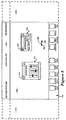
- the display screen 60 of the display 50 is shown in additional detail. Illustrated within the display 60, is a graphic user interface which includes a working area 100, a title bar 102 and a function bar 104, as illustrated.
- the function bar 104 includes a plurality of button functions which may be selected by the user, including a system setup function 106, a production log 108, a device controller 110, mast lists 112, edit control 114, edit bins 116, an audio mixer 188, special effects 120, a view source function 122, tool functions 124 and a production directory 126.
- the functions illustrated in Figure 2 are representative of a broad category of functions which may be utilized by the present invention.
- the present invention is illustrated with reference to a video edit graphic user interface, it will be appreciated that numerous functions may be applicable for use in conjunction with the present invention in other systems beyond that of video editing.
- the working area 100 comprises the "real" workspace of the display screen 60 which is visible to the user.
- the working area 100 is defined by a length 130 and width 132.
- the working area 100 comprises the real desktop space in which the user may operate on the functions selected from the function bar 104.
- a cursor 136 is provided which is controlled by using cursor control device 52, as previously described with respect to Figure 1, and discussed more fully below.
- a "virtual" workspace is also defined which includes areas 140 and 145 in Figure 2.
- the "desktop" available to a user comprises the combined length of the real and virtual working areas and is defined by length 150 and the width 132, as shown in Figure 2. Accordingly, the total workspace available in the desktop metaphor to the user of the present invention is the combined areas 100, 140 and 145.
- the virtual and real workspaces dynamically change. Therefore, for purposes of this specification, the real workspace constitutes that portion of the desktop visible to the user, and the virtual workspace constitutes that portion of the desktop which is not visible to the user at any one time.
- cursor 136 includes a left arrowhead 165 and a right arrowhead 168.
- the workspace comprising the virtual workspaces 140 and 145 and real workspace 100, may be panned left or right by depressing an appropriate switch 54 or 56 on the cursor control device 52.
- the depression of left switch 56 results in the workspace being panned horizontally to the left and in the direction of the arrowhead 165.
- the depression of switch 54 results in the workspace panning right in the direction of arrowhead 168, as will be illustrated.
- a button function such as system setup 106 may be selected by placing cursor 136 over a portion of the function on the function bar 104 and momentarily clicking either switch 54 or 56 on the cursor control device 52.
- the movement of the cursor 136 over the function bar 104 results in a modification of the visual appearance of the cursor to that of a single arrow. (See cursor 58 in Figure 1).
- the movement of the cursor 136 into the working area 100 results in the modification of the visual appearance of the cursor once again, such that the cursor 136 appears as shown in Figure 2.
- System setup window 170 includes a drag bar 175 for selectively moving the window 170 over the working area 100.
- the cursor 136 is placed over a portion of bar 175, and a switch (either switch 54 or 56) on cursor control device 52 is depressed.
- the window 170 may then be selectively dragged to any location within the working area 100 and positioned for the convenience of the user.
- window 170 further includes a close box 180 which may be activated to close window 170 and redisplay the button function on the function bar 104.
- the window 170 may be closed by placing the cursor 136 over a portion of box 180 and momentarily depressing ("clicking") a switch on cursor control device 52.
- the window may comprise the control panel of the video editing device, such as an audio mixer, video tape recorder or the like, or may include areas in which text, graphics, or moves (such as for example, various scenes and takes) are displayed. Accordingly, it will be appreciated that the functions illustrated in the figures are for illustration only, and that in particular window characteristics shown are not to be considered limitations on the present invention.
- window 170 includes a floating window activation button 200.
- the button 200 in the presently preferred embodiment, includes the notation "UP" (or alternatively down “DN").
- the present invention permits a user to selectively set each opened window on the desktop (comprising both the real area 100 and virtual areas 145 and 140) to either float above the desktop, or appear to the user to be affixed to the desktop.
- each window upon selecting a function along the function bar 104, each window is opened (for example window 170) with the floating window activation button 200 selected by default in the "UP" (not affixed) configuration.
- window 170 "floats" above the desktop comprising the real working area 100 and virtual areas 145 and 140.
- the window 170 floats above the desktop such that it remains in the same relative position as viewed by the user regardless of which direction the desktop is panned.
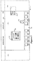
- switch 54 has been depressed by the user, such that the desktop has panned to the right in the direction of arrowhead 168. As shown, although the desktop has panned to the right, the window 170 remains stationary with respect to the user.
- window 170 is illustrated with the floating window activation button 200 in the down ("DN") position.
- the audio mix button function has been activated by a user, resulting in the display of the audio mix window 210.
- window 210 includes a floating window activation button 215 which is in the "UP" position, and thereby results in the window 210 floating above the working area 100 in a position fixed relative to the user.
- the user depresses switch 54 on the cursor control device 52, thereby panning the desktop to the right as viewed by the user (in the direction of arrow 168).
- panning the desktop to the right in the direction of arrow 168 results in the window 170 being obscured from view as it passes out of area 100 and into the virtual desktop 140 (shown for illustration in dashed lines).
- activation button 200 of the window 170 was selected by the user to be in the down ("DN") position, and accordingly, the window 170 moves relative to the user as if it is affixed to the desktop.
- window 170 pans with the desktop, whether to the right or to the left, as the desktop is panned by the user using the cursor control device 52.
- audio mix window 210 remains stationary in space relative to the user, such that it appears to "float" over the desktop. Since window 210 floats over the desktop, it does not move relative to the user as the desktop is panned right or left.
- window 170 is shown in Figure 6 in dashed lines, that the dashed lines are for illustration only, and that the present embodiment, those items illustrated in the figures in dashed lines are not visible to the user, since they fall outside of the real working area 100 of the desktop which comprises the screen 60.
- Figure 7 shows the panning left of the desktop by the user.
- the user depresses switch 56 on cursor control device 52 to initiate panning left (in direction of arrow 165 on cursor 136).
- window 210 remains stationary in space and floats over the desktop as a result of activation button 215 being in an "UP" position.
- window 170 has moved such tat it is partially visible in the real working area 100 as the desktop is panned left by the user.
- continuing to pan the desktop left in the direction of arrow 165 results in the window 170 appearing to traverse the real working area 100, and moving partially into the virtual desktop area 145 as the desktop is panned.
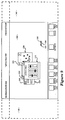
- window 210 in which floating window activation button 215 is in an "UP” position, and window 170 in which the activation button 200 has been selected to be in a down (“DN") position.
- window 230 has been opened in which the activation button 235 has been selected by the user to be in a down (“DN") position, thereby affixing it to the desktop.
- window 210 floats above the desktop, that it appears to be “closer” to the user and thereby overlays windows which have been affixed to the desktop by being placed in a down (“DN”) position (in the present example, windows 170 and 230).
- window 210 remains stationary in space relative to the user since the function 215 is in the UP (floating) position. Also illustrated in Figure 10 is the movement of windows 230 and 170 relative to the user as the desktop pans left. As shown, window 170 is only partially visible, with a portion of window 170 having entered the virtual workspace 145. Similarly, as shown in Figure 10, window 230 has passed behind the window 210 and is partially obscured by window 210.
- the desktop of the present invention includes the real working area 100 (real workspace) and virtual areas 140 and 145 (virtual workspace).
- the entire desktop comprising the graphic user interface of the present invention includes areas 100, 140 and 145 having an overall length identified in figure 11 as length 250.
- window 170 is set such that the floating window activation button function 200 is in an UP (floating) position.
- window 210 has been selected such that the activation button 2315 is in the down ("DN") position.
- window 230 is provided in which the activation button 235 has been selected by the user to be in the UP position.
- An additional window 300 is illustrated in which its activation button 310 is in down ("DN") position.
- a centre line 320 conceptually represents the centre line of the real working area 100, comprising display screen 60 as viewed by the user.
- panning the desktop to the right results in the system window maintaining its position relative to the centre line 320 and the user since the floating window activation function button 200 is in an UP (unaffixed) position.
- window 230 remains fixed relative to the user since its activation button 235 is in an UP position as well.
- window 210 moves with the desktop as a result of activation button 215 being in a down (affixed) position, as does window 300 as illustrated in Figure 11b.
- Windows 170 and 230 maintain their same relative position to the user and float above the desktop.
- Windows 210 and 300 being "affixed" to the desktop move with the desktop to the left, as shown in Figure 11c.
- the present invention as described provides an improved graphic user interface for use in a window-based display system. While the present invention has been described with reference to Figures 1 through 11, it will be appreciated that the figures are for illustration only, and do not limit the spirit and scope of the invention. For example, all of the figures may have, by necessity, used example windows having certain attributes and/or functions, it will be appreciated that the invention is not limited by the specific examples provided.
Landscapes
- Engineering & Computer Science (AREA)
- Theoretical Computer Science (AREA)
- General Engineering & Computer Science (AREA)
- Human Computer Interaction (AREA)
- Physics & Mathematics (AREA)
- General Physics & Mathematics (AREA)
- Multimedia (AREA)
- Digital Computer Display Output (AREA)
- User Interface Of Digital Computer (AREA)
Description
- The present invention relates to apparatus and methods for displaying graphic information, and more particularly, the present invention relates to a computer controlled display system for displaying and manipulating overlapping windows of data on a desktop workspace.
- Over the past decade, a variety of graphic user interfaces have been developed to ease human interaction with computer systems. Many display systems utilize metaphors in the design of the interface as a way of maximising human familiarity, and conveying information between the user and the computer. It is common for computer systems incorporating so-called "object oriented" display systems to utilize multiple "windows" on a display in which combinations of text and graphics are disposed. The display systems utilize familiar metaphors, such as desktops, control panels, notebooks and the like, such that the interface takes advantage of existing human mental structures to permit a user to draw upon the metaphor analogy to understand the requirements of the particular computer system.
- It is well know that designing around a familiar metaphor helps reduce human learning time. (See for example, Patrick Chan, "Learning Considerations in User Interface Design: The Room Model", Report CS-84-16, University of Waterloo Computer Science Department, Onatario, Canada, July 1984, and the references cited therein.) The ability to operate on images or objects which relate the user to actual objects on, for example, a desktop, results in a stronger man-machine interface. (See for example, D.Robson, "Object Oriented Software Systems", BYTE, August 1991, page 74, Vol.6, No.8; L.Tesler, "The Smalltalk Environment", BYTE, August 1981, page 90, Vol.6, No.8; and Smith, et al., "Star User Interface: An Overview", National Computer Conference, 1982).
- Research in interface design using metaphors in man-machine interfaces may be applied to computer controlled editing systems to incorporate and integrate various production media resources, such as special effects, music, graphics and the like. In the case of an editing system, a variety of resources must be integrated, scheduled and coordinated with one another to obtain a complete multi-media product. Users of computer controlled editing systems are generally familiar with the individual resources and the coordination of those resources to develop a finished product. Accordingly, the "windows" utilized in a video editing system may be designed such that the metaphor of the interface takes advantage of the knowledge of the user in operating discrete devices (for example, a video tape recorder or music synthesizer). The window may, therefore, take the form of a control panel for the video tape recorder, which includes the controls of play, reverse, record and the like. Similarly, the window may provide an area on the display screen in which movies, takes, or particular scenes are displayed for the user to edit.
- One problem associated with many object-oriented graphic user interfaces, is that the display screen provides only a limited size workspace in which to operate on the windows. For example, in the case of a video editing workstation, windows corresponding to resource such as video tape recorders, music synthesizers, audio tape recorders and music mixers may be opened and operating concurrently on the display. Given the limited space of the display screen, the workspace (known as the "desktop") which is available to the user may become cluttered and confusing to operate. The user may be required to frequently move windows in the workspace to make room for other windows to be opened, or alter the priority in which the windows are displayed and overlap one another to gain access to a desired window.
- The idea that the usable area of the desktop as represented in the computer memory may be larger than the actual area of the desktop which is displayed at any one time is known; and systems which implement it utilise a panning facility to enable the user to pan the current viewable area across the extent of the virtual desktop. An example of such a system, corresponding to the pre-characterising part of
claim 1, is described in IBM Technical Disclosure Bulletin, vol.35, no.6, November 1992, New York, US, pages 304-305, XP 000314151 'Variable Distance Panning'. - As will be described, the present invention provides a method and apparatus for increasing the usable workspace area in a window-based graphic user interface. The present invention provides a real and a virtual desktop comprising the entire workspace, and the ability of the user to pan horizontally across the entire area in a contiguous fashion.
- According to the present invention, there is provided a computer display system including a central processing unit (CPU) coupled to a display having a display screen, such that data is displayed on said display screen in a plurality of windows, comprising:
- user interface generation means coupled to said CPU for displaying said data in said windows, said user interface generation means generating and displaying a user interface including a desktop having a visible portion and a virtual portion, wherein said visible portion corresponds to that portion of the said desktop currently visible on said display screen, said virtual portion corresponding to that portion of said desktop currently not visible to said user on said display screen;
- panning means coupled to said CPU for selectively panning said desktop in at Least two directions, such that said desktop pans in a direction selected by a user, and that portion of said desktop within said visible portion is displayed to said user; characterised in that said windows displayed on said desktop include attachment means for selectively affixing at least one of said windows to said desktop, such that if a window is affixed to said desktop said window moves with said desktop in the direction said desktop is panned, and remains stationary relative to said desktop.
-
- The present invention provides apparatus and methods for use in computer display systems, and in particular, display systems having object-oriented graphic user interfaces with overlapping windows. A display system including at least one central processing unit (CPU) is coupled through appropriate input/output (I/O) circuitry to input devices, such as a cursor control device. The CPU is further coupled to a hard disk drive for the storage of programs and data, and is coupled to a network through which the CPU may communicate with a variety of system resources such as editors, music synthesizers, graphic generators, and the like. The CPU is also coupled to a display device on which the present invention's users interface is displayed. Utilizing the teachings of the present invention, a "real" and a "virtual" workspace is defined comprising the entire desktop available to the user. The real workspace constitutes that portion of the desktop visible to the user on the display at any one time. The virtual workspace comprises a predefined extension of the screen area of the display which is also available for use by the user. The virtual workspace constitutes that portion of the desktop which is not visible to the user at any one time. The real and virtual workspaces comprise the entire desktop available to the user for opening and manipulating windows in the display system. In addition, windows may be selectively affixed to the desktop. Using the cursor control device, a user may pan horizontally over the desktop (both real and virtual). If a window has been affixed to the desktop, the window maintains it position relative to the desk top, and appears to move relative to the user. If the window is not affixed to the desktop, it appears to "float" above the desktop and remains fixed relative to the user as the desktop is panned.
- The invention will be further described by way of non-limitative example with reference to the accompanying drawings, in which:-
- Figure 1 is a functional block diagram illustrating one possible computer display system incorporating the teachings of the present invention.
- Figure 2 shows a representative display screen illustrating the virtual and real workspace comprising the desktop of the present invention.
- Figure 3 illustrates the graphic user interface of the present invention in which a system setup window has been opened and the window activation button is in the "UP" position.
- Figure 4 illustrates a horizontal panning of the desktop wherein the system setup window maintains a fixed position relative to the user and floats above the desktop.
- Figure 5 illustrates the graphic user interface of the present invention wherein the system set up window activation button is down ("DN") and the audio mix activation button is "UP".
- Figure 6 illustrates the horizontal panning of the present invention wherein the system setup window has panned horizontally into the virtual workspace, with the desktop and the audio mix window remains in a fixed position relative to the user.
- Figure 7 illustrates panning left in the system illustrated in Figure 6.
- Figure 8 illustrates the continued left panning of the system illustrated in Figure 7.
- Figure 9 illustrates the present invention wherein three overlapping windows have been opened.
- Figure 10 illustrates the left panning of the system illustrated in Figure 9.
- Figure 11 conceptually illustrates the operation of the present invention panning left and right, and moving windows between the real and virtual workspace on the desktop.
-
- The detailed descriptions which follow are presented largely in terms of display images, algorithms and symbolic representations of operations of data bits within a computer memory. These algorithmic descriptions and representations are the means used by those skilled in the data processing arts to most effectively convey the substance of their work to others skilled in the art.
- An algorithm is here, and generally, conceived to be a self consistent sequence of steps leading to a desired result. These steps are those requiring physical manipulations of physical quantities. Usually, though not necessarily, these quantities take the form of electrical or magnetic signals capable of being stored, transferred, combined, compared, and otherwise manipulated. It proves convenient at times, principally for reasons of common usage, to refer to these signals as bits, values, elements, symbols, characters, images, terms, numbers or the like. It should be borne in mind, however, that all of these and similar terms are to be associated with the appropriate physical quantities and are merely convenient labels provided to these quantities.
- In the present case, the operations are machine operations performed in conjunction with a human operator. Useful machines for performing the operations of the present invention include general purpose digital computers or other similar devices. In all cases, there should be borne in mind the distinction between the method operations of operating a computer and the method of computation itself.
- The present invention relates to method steps for operating a computer and processing electrical or other physical signals to generate other desired physical signals. The present invention also relates to apparatus for performing these operations. This apparatus may be specially constructed for the required purposes, or it may comprise a general purpose computer selectively activated or reconfigured by a computer program stored in the computer. The algorithms, methods and apparatus presented herein are not inherently related to any particular computer. In particular, various general purpose machines may be used with programs in accordance with the teachings herein, or it may prove more convenient to construct more specialised apparatus to perform the required method steps. The required structure for a variety of these machines will appear from the description given below. Machines which may perform the functions of the present invention include those manufactured by Sony Corporation of America, as well s other manufacturers of computer systems.
- The present invention discloses apparatus and methods for displaying graphic or other information in a window-based system on a computer display. In the following description, numerous specific details are set forth such as computer system configurations, window elements, icons, desktop sizes, metaphors, window configurations and arrangements, etc. in order to provide a thorough understanding of the present invention. However, it will be apparent to one skilled in the art that the present invention may be practised without these specific details. In other instances, well known circuits, structures and the like are not described in detail so as not to obscure the present invention unnecessarily.
- Referring now to Figure 1, the hardware configuration of the present invention is conceptually illustrated. The Figure illustrates a computer system for generating a window-based graphic user interface in accordance with the teachings of the present invention. As illustrated, the computer system includes a
computer 20 which comprises four major components. The first of these is an input/output (I/O)circuit 22, which is used to communicate information in appropriately structured form to and from other portions of thecomputer 20. In addition,computer 20 includes a central processing unit (CPU) 24 coupled to the I/O circuit 22 and to amemory 26. These elements are those typically found in most computers and, in fact,computer 20 is intended to be representative of a broad category of data processing devices. - Also shown in Figure 1 is a
keyboard 30 for inputting data and commands intocomputer 20 through the I/O circuit 22, as is well known. - Similarly, a
CD ROM 34 is coupled to the I/O circuit 22 for providing additional programming capacity to the system illustrated in Figure 1. It will be appreciated that additional devices may be coupled to thecomputer 20 for storing data, such as magnetic tape drives, buffer memory devices, and the like. Anetwork interface 36 is coupled to both thememory 26 and the I/O circuit 22, to permit thecomputer 20 to communicate along a network 38 which is coupled to other system resources. For example, in a video editing environment, thecomputer 20 may be coupled over the network 38 to avideo tape recorder 40, amusic synthesizer 42, anaudio tape recorder 44, and,special effects resource 46, as shown. - A display monitor 50 is coupled to the
computer 20 through the I/O circuit 22. Any well know variety of cathode ray tube (CRT), liquid crystal or other displays may be utilized asdisplay 50. Acursor control device 52 includesswitches CPU 24 in accordance with the teachings of the present invention. Cursor control device 52 (commonly referred to as a "mouse") permits a user to select various command modes, modify graphic data, and input otherdata utilizing switches cursor control device 52 permits a user to selectively position acursor 58 at any desired location on adisplay screen 60 of thedisplay 50. As illustrated in Figure 1, thecursor 58 is disposed with awindow 65 in the present invention's graphic user interface, to be described more fully below. Moreover, in the presently preferred embodiment, the present invention's window-based user interface is generated and displayed using software stored in eithermemories CD ROM 34, and executed by theCPU 24. - In the presently preferred embodiment,
cursor control 52 utilizes well known apparatus and methods forsignalling CPU 24 of positional changes orcursor 58 by movement of the cursor control over a surface. However, it will be appreciated by one skilled in the art that a variety of well known cursor control devices may be utilized by the present invention, including other control devices such as mechanical mice, trackballs, joy sticks, graphic tablets, other keyboard inputs and the like. Thecursor control 52 in Figure 1 is intended to encompass all such equivalent devices. For convenience in this specification, thecursor control device 52 and the equivalents thereof, are collectively referred to a "mouse". - Referring now to Figure 2, the
display screen 60 of thedisplay 50 is shown in additional detail. Illustrated within thedisplay 60, is a graphic user interface which includes a workingarea 100, atitle bar 102 and afunction bar 104, as illustrated. Thefunction bar 104 includes a plurality of button functions which may be selected by the user, including asystem setup function 106, aproduction log 108, adevice controller 110, mast lists 112,edit control 114, editbins 116, an audio mixer 188,special effects 120, aview source function 122, tool functions 124 and aproduction directory 126. It will be appreciated by one skilled in the art, that the functions illustrated in Figure 2 are representative of a broad category of functions which may be utilized by the present invention. For example, although the present invention is illustrated with reference to a video edit graphic user interface, it will be appreciated that numerous functions may be applicable for use in conjunction with the present invention in other systems beyond that of video editing. - The working
area 100 comprises the "real" workspace of thedisplay screen 60 which is visible to the user. The workingarea 100 is defined by alength 130 andwidth 132. For purposes of this specification, the workingarea 100 comprises the real desktop space in which the user may operate on the functions selected from thefunction bar 104. Additionally, as shown, acursor 136 is provided which is controlled by usingcursor control device 52, as previously described with respect to Figure 1, and discussed more fully below. - Utilizing the teachings of the present invention, a "virtual" workspace is also defined which includes
areas length 150 and thewidth 132, as shown in Figure 2. Accordingly, the total workspace available in the desktop metaphor to the user of the present invention is the combinedareas - Referring once again to Figure 2, as shown,
cursor 136 includes aleft arrowhead 165 and aright arrowhead 168. As will be described, the workspace comprising thevirtual workspaces real workspace 100, may be panned left or right by depressing anappropriate switch cursor control device 52. The depression ofleft switch 56 results in the workspace being panned horizontally to the left and in the direction of thearrowhead 165. Similarly, the depression ofswitch 54 results in the workspace panning right in the direction ofarrowhead 168, as will be illustrated. A button function such assystem setup 106 may be selected by placingcursor 136 over a portion of the function on thefunction bar 104 and momentarily clicking either switch 54 or 56 on thecursor control device 52. In the presently preferred embodiment, the movement of thecursor 136 over thefunction bar 104 results in a modification of the visual appearance of the cursor to that of a single arrow. (Seecursor 58 in Figure 1). Subsequent to the selection of a function on thefunction bar 104, the movement of thecursor 136 into the workingarea 100, results in the modification of the visual appearance of the cursor once again, such that thecursor 136 appears as shown in Figure 2. - Referring now to Figure 3, the button
function system setup 106 has been selected by a user.System setup window 170 includes adrag bar 175 for selectively moving thewindow 170 over the workingarea 100. In operation, thecursor 136 is placed over a portion ofbar 175, and a switch (either switch 54 or 56) oncursor control device 52 is depressed. Thewindow 170 may then be selectively dragged to any location within the workingarea 100 and positioned for the convenience of the user. As shown,window 170 further includes aclose box 180 which may be activated to closewindow 170 and redisplay the button function on thefunction bar 104. Thewindow 170 may be closed by placing thecursor 136 over a portion ofbox 180 and momentarily depressing ("clicking") a switch oncursor control device 52. - As illustrated in Figure 3, the activation of any one of the functions identified and displayed along the
function bar 104 results in the opening of a corresponding window (in the example illustrated in Figure 3, window 170). It will be appreciated by one skilled in the art that the functions illustrated in Figure 3 and disposed in thefunction bar 104 are examples of the type of functions which may be utilized using the teachings of the present invention. Depending on the particular application in which the graphic user interface of the present invention is used, numerous other functions may be displayed along thefunction bar 104. Additionally, as illustrated in Figure 3, and the remaining figures in this specification, each of the windows (for example window 170) corresponding to the functions displayed alongfunction bar 104 have unique characteristics. Depending on the function which is selected, the window may comprise the control panel of the video editing device, such as an audio mixer, video tape recorder or the like, or may include areas in which text, graphics, or moves (such as for example, various scenes and takes) are displayed. Accordingly, it will be appreciated that the functions illustrated in the figures are for illustration only, and that in particular window characteristics shown are not to be considered limitations on the present invention. - Referring again to Figure 3,
window 170 includes a floatingwindow activation button 200. As illustrated in Figure 3, thebutton 200 in the presently preferred embodiment, includes the notation "UP" (or alternatively down "DN"). As will be described, the present invention permits a user to selectively set each opened window on the desktop (comprising both thereal area 100 andvirtual areas 145 and 140) to either float above the desktop, or appear to the user to be affixed to the desktop. In the present embodiment, upon selecting a function along thefunction bar 104, each window is opened (for example window 170) with the floatingwindow activation button 200 selected by default in the "UP" (not affixed) configuration. - Referring now to Figure 4, the operation of the present invention will be described when the floating
window activation button 200 is in the "UP" (not affixed) position forwindow 170. As illustrated,window 170 "floats" above the desktop comprising thereal working area 100 andvirtual areas window 170 floats above the desktop such that it remains in the same relative position as viewed by the user regardless of which direction the desktop is panned. In the example illustrated,switch 54 has been depressed by the user, such that the desktop has panned to the right in the direction ofarrowhead 168. As shown, although the desktop has panned to the right, thewindow 170 remains stationary with respect to the user. - Referring now to Figure 5,
window 170 is illustrated with the floatingwindow activation button 200 in the down ("DN") position. In addition, the audio mix button function has been activated by a user, resulting in the display of theaudio mix window 210. As shown,window 210 includes a floatingwindow activation button 215 which is in the "UP" position, and thereby results in thewindow 210 floating above the workingarea 100 in a position fixed relative to the user. - Assume for the sake of example that the user desires to pan the desktop illustrated in Figure 5 to the right. In accordance with the teachings of the present invention, the user depresses
switch 54 on thecursor control device 52, thereby panning the desktop to the right as viewed by the user (in the direction of arrow 168). As shown in Figure 6, panning the desktop to the right in the direction ofarrow 168, results in thewindow 170 being obscured from view as it passes out ofarea 100 and into the virtual desktop 140 (shown for illustration in dashed lines). As previously described with reference to Figure 5,activation button 200 of thewindow 170 was selected by the user to be in the down ("DN") position, and accordingly, thewindow 170 moves relative to the user as if it is affixed to the desktop. As such, thewindow 170 pans with the desktop, whether to the right or to the left, as the desktop is panned by the user using thecursor control device 52. However, as shown in Figure 6,audio mix window 210 remains stationary in space relative to the user, such that it appears to "float" over the desktop. Sincewindow 210 floats over the desktop, it does not move relative to the user as the desktop is panned right or left. Additionally, it will be again noted that althoughwindow 170 is shown in Figure 6 in dashed lines, that the dashed lines are for illustration only, and that the present embodiment, those items illustrated in the figures in dashed lines are not visible to the user, since they fall outside of thereal working area 100 of the desktop which comprises thescreen 60. - Referring now to Figure 7, subsequent to the panning right illustrated in Figure 6, Figure 7 shows the panning left of the desktop by the user. In the present embodiment, the user depresses
switch 56 oncursor control device 52 to initiate panning left (in direction ofarrow 165 on cursor 136). As illustrated in Figure 7,window 210 remains stationary in space and floats over the desktop as a result ofactivation button 215 being in an "UP" position. However, as illustrated in Figure 7,window 170 has moved such tat it is partially visible in thereal working area 100 as the desktop is panned left by the user. As illustrated in Figure 8, continuing to pan the desktop left in the direction ofarrow 165 results in thewindow 170 appearing to traverse thereal working area 100, and moving partially into thevirtual desktop area 145 as the desktop is panned. - Referring now to Figure 9, there is shown an example of the present invention in which three windows are simultaneously open and active. There is shown
window 210 in which floatingwindow activation button 215 is in an "UP" position, andwindow 170 in which theactivation button 200 has been selected to be in a down ("DN") position. In addition, awindow 230 has been opened in which theactivation button 235 has been selected by the user to be in a down ("DN") position, thereby affixing it to the desktop. It should be noted that sincewindow 210 floats above the desktop, that it appears to be "closer" to the user and thereby overlays windows which have been affixed to the desktop by being placed in a down ("DN") position (in the present example,windows 170 and 230). - Assume for the sake of example that a user desires to pan the desktop of the present invention to the left (in the direction of arrow 165). The user depresses
switch 56 oncursor control device 52 and the desktop pans to the left relative to the user facing the display. As illustrated in Figure 10,window 210 remains stationary in space relative to the user since thefunction 215 is in the UP (floating) position. Also illustrated in Figure 10 is the movement ofwindows window 170 is only partially visible, with a portion ofwindow 170 having entered thevirtual workspace 145. Similarly, as shown in Figure 10,window 230 has passed behind thewindow 210 and is partially obscured bywindow 210. - Referring to Figures 11a-11c, the operation of the present invention is conceptually illustrated to assist the reader in understanding the present invention's overall function and utility. As previously described, the desktop of the present invention includes the real working area 100 (real workspace) and
virtual areas 140 and 145 (virtual workspace). Thus, the entire desktop comprising the graphic user interface of the present invention includesareas length 250. Assume for the sake of example thatwindow 170 is set such that the floating windowactivation button function 200 is in an UP (floating) position. In addition, assume for the sake of example thatwindow 210 has been selected such that the activation button 2315 is in the down ("DN") position. As illustrated in Figure 11,window 230 is provided in which theactivation button 235 has been selected by the user to be in the UP position. Anadditional window 300 is illustrated in which itsactivation button 310 is in down ("DN") position. Acentre line 320 conceptually represents the centre line of thereal working area 100, comprisingdisplay screen 60 as viewed by the user. - As illustrated in Figure 11b, panning the desktop to the right results in the system window maintaining its position relative to the
centre line 320 and the user since the floating windowactivation function button 200 is in an UP (unaffixed) position. Similarly,window 230 remains fixed relative to the user since itsactivation button 235 is in an UP position as well. During the panning of the desktop to the right,window 210 moves with the desktop as a result ofactivation button 215 being in a down (affixed) position, as doeswindow 300 as illustrated in Figure 11b. - Referring now to Figure 11c, panning to the left is shown in which
windows Windows - Accordingly, the present invention as described provides an improved graphic user interface for use in a window-based display system. While the present invention has been described with reference to Figures 1 through 11, it will be appreciated that the figures are for illustration only, and do not limit the spirit and scope of the invention. For example, all of the figures may have, by necessity, used example windows having certain attributes and/or functions, it will be appreciated that the invention is not limited by the specific examples provided.
- In addition, although the present invention has been described with respect to panning only to the left or right, it will be appreciated by one skilled in the art that vertical panning using the teachings of the present invention may also be provided. Moreover, it will be noted that the present invention may be realized using a variety of computer programming languages and hardware, and is not limited to any particular hardware or software. In as much as the various features and aspects of the present invention are not static events, and are perceived by the user as having motion, the reader is referred to a video tape entitled "Graphical User Interface Incorporating A Horizontal Panning Workspace" submitted by the applicant concurrent with the filing of the application on which this patent is based.
Claims (33)
- A computer display system including a central processing unit (CPU) (24) coupled to a display (50) having a display screen (60), such that data is displayed on said display screen in a plurality of windows, comprising:user interface generation means coupled to said CPU for displaying said data in said windows, said user interface generation means generating and displaying a user interface including a desktop having a visible portion (100) and a virtual portion (140,145), wherein said visible portion (100) corresponds to that portion of the said desktop currently visible on said display screen (60), said virtual portion corresponding to that portion of said desktop currently not visible to said user on said display screen;panning means (52,30) coupled to said CPU for selectively panning said desktop in at least two directions, such that said desktop pans in a direction selected by a user, and that portion of said desktop within said visible portion is displayed to said user; characterised in that said windows displayed on said desktop include attachment means (200) for selectively affixing at least one of said windows (170) to said desktop, such that if a window (170) is affixed to said desktop said window (170) moves with said desktop in the direction said desktop is panned, and remains stationary relative to said desktop.
- The computer display system as defined by claim 1, wherein in the event said window (170) is not affixed to said desktop, said window remains stationary with respect to said user, such that said unaffixed window appears to said user to float above said desktop as said desktop is panned.
- The computer display system as defined by claim 2, wherein said panning means includes a cursor control device (52) coupled to said CPU and operable by said user.
- The computer display system as defined by claim 2 or 3, wherein said attachment means (200) includes a floating window activation button in each of said windows (170) displayed on said display having two states, a first state corresponding to an affixed state and a second state corresponding to said unaffixed state.
- The computer display system as defined by claim 4, wherein said activation button (200) displays the notation DN if said function has been placed in said affixed state.
- The computer display system as defined by claim 5, wherein said activation button (200) displays the notation UP if said function has been placed in said unaffixed state.
- The computer display system as defined by any one of claims 2 to 4, further including a function bar (104) on said display screen on which is displayed a plurality of functions selectable by said user.
- The computer display system as defined by Claim 7, wherein said function bar (104) is horizontally disposed along the lower portion of said display screen.
- The computer display system as defined by claim 8, further including a title bar (102) disposed horizontally across the top of said display screen.
- The computer display system defined by claim 9, wherein said function bar (104) remains stationary relative to said user.
- The computer display system as defined by claim 9, wherein said title bar pans with said desktop.
- The computer display system as defined by any one of claims 2 to 11, wherein in the event said windows overlay one another on said desktop, windows (170) unaffixed to said desktop appear to said user to float above windows (210) which are affixed to said desktop.
- The computer display system as defined by claim 12, wherein said panning is horizontal.
- The computer display system as defined by claim 3, wherein said desktop further includes a cursor (136) displayed on said display screen and controlled by said cursor control device (52), said cursor having the shape of an arrow including a body and two opposing arrow heads, one (165) of said arrow heads pointing left and one arrow head (168) pointing right with respect to said user viewing said display, said arrow heads corresponding to panning directions of said desktop.
- The computer display system as defined by claim 14, wherein said cursor control device includes at least two switches (54,56) coupled to said CPU, said switches corresponding to said panning directions.
- The computer display system as defined by claim 15, wherein if said cursor is placed by said user using said cursor control device over one of said windows displayed on said desktop, said CPU modifies the shape of said cursor.
- The computer display system as defined by claim 16, wherein said modified cursor has the shape of an arrow having only a single arrow head.
- A method for increasing the usable workspace for a user in a computer display system including a central processing unit (CPU) (24) coupled to a display (50) having a display screen (60), such that data is displayed on said display screen in a plurality of windows, comprising the steps of:generating and displaying a user interface including a desktop having a visible portion (100) and a virtual portion (150,145), wherein said visible portion (100) corresponds to that portion of said desktop currently visible on said display screen, and virtual portion (140,145) corresponding to that portion of said desktop currently not visible to said user on said display screen;panning said desktop in at least two directions, such that said desktop pans in a direction selected by a user, and that portion of said desktop within said visible portion is displayed to said user; andselectively affixing at least one (170) of said windows to said desktop, such that if a window is affixed to said desktop said window (170) moves with said desktop in the direction said desktop is panned, and remains stationary relative to said desktop; characterised in that in the event said window (170) is not affixed to said desktop, said window remains stationary with respect to said user, such that said unaffixed window appears to said user to float above said desktop as said desktop is panned.
- The method as defined by claim 18, wherein said user uses a cursor control device (52) coupled to said CPU and operable by said user to pan said desktop.
- The method as defined by claim 18, wherein each of said windows includes a floating window activation button having two states, a first state corresponding to an affixed state and a second state corresponding to said unaffixed state.
- The method as defined by claim 20, wherein said activation button displays the notation DN if said function has been placed in said affixed state.
- The method as defined by claim 21, wherein said activation button displays the notation UP if said function has been placed in said unaffixed state.
- The method as defined by claim 18 further including a function bar (104) on said computer display screen on which is displayed a plurality of functions selectable by said user.
- The method as defined by claim 23, wherein said function bar (104) is horizontally disposed along the lower portion of said display screen.
- The method as defined by claim 24 further including a title bar (102) disposed horizontally across the top of said computer display screen.
- The method as defined by claim 25, wherein said function bar (104) remains stationary relative to said user.
- The method as defined by claim 25, wherein said title bar pans with said desktop.
- The method as defined by claim 18, wherein in the event said windows overlay one another on said desktop, windows (107) unaffixed to said desktop appear to said user to float above windows (200) which are affixed to said desktop.
- The method as defined by claim 28, wherein said panning is horizontal.
- The method as defined by claim 19, wherein said desktop further includes a cursor (136) displayed on said display screen and controlled by said cursor control device, said cursor having the shape of an arrow including a body and two opposing arrow heads, one (165) of said arrow heads pointing left and one arrow head (168) pointing right with respect to said user viewing said display, said arrow heads corresponding to panning directions of said desktop.
- The method as defined by claim 30, wherein said cursor control device includes at least two switches (54,56) coupled to said CPU, said switches corresponding to said panning directions.
- The method as defined by claim 31, wherein if said cursor is placed by said user using said cursor control device over one of said windows displayed on said desktop, said CPU modifies the shape of said cursor.
- The method as defined by claim 32, wherein said modified cursor has the shape of an arrow having only a single arrow head.
Applications Claiming Priority (2)
| Application Number | Priority Date | Filing Date | Title |
|---|---|---|---|
| US2187293A | 1993-02-24 | 1993-02-24 | |
| US21872 | 1993-02-24 |
Publications (3)
| Publication Number | Publication Date |
|---|---|
| EP0613080A2 EP0613080A2 (en) | 1994-08-31 |
| EP0613080A3 EP0613080A3 (en) | 1995-12-20 |
| EP0613080B1 true EP0613080B1 (en) | 2000-09-13 |
Family
ID=21806607
Family Applications (1)
| Application Number | Title | Priority Date | Filing Date |
|---|---|---|---|
| EP94300776A Expired - Lifetime EP0613080B1 (en) | 1993-02-24 | 1994-02-02 | Graphical user interface incorporating a panning workspace with means for affixing windows |
Country Status (4)
| Country | Link |
|---|---|
| EP (1) | EP0613080B1 (en) |
| JP (1) | JPH06250811A (en) |
| KR (1) | KR100324836B1 (en) |
| DE (1) | DE69425842T2 (en) |
Families Citing this family (25)
| Publication number | Priority date | Publication date | Assignee | Title |
|---|---|---|---|---|
| JP2519815B2 (en) * | 1990-03-01 | 1996-07-31 | 三菱電機株式会社 | Photomask and manufacturing method thereof |
| US6078380A (en) * | 1991-10-08 | 2000-06-20 | Nikon Corporation | Projection exposure apparatus and method involving variation and correction of light intensity distributions, detection and control of imaging characteristics, and control of exposure |
| US5420417A (en) * | 1991-10-08 | 1995-05-30 | Nikon Corporation | Projection exposure apparatus with light distribution adjustment |
| JP3069417B2 (en) * | 1991-11-21 | 2000-07-24 | シャープ株式会社 | Inspection method of phase shift mask |
| JP3141471B2 (en) * | 1991-12-25 | 2001-03-05 | 株式会社ニコン | Disc medium manufacturing method and manufacturing apparatus, exposure method and exposure apparatus |
| US6249335B1 (en) * | 1992-01-17 | 2001-06-19 | Nikon Corporation | Photo-mask and method of exposing and projection-exposing apparatus |
| JPH05217855A (en) * | 1992-02-01 | 1993-08-27 | Nikon Corp | Illumination apparatus for exposure |
| JP3075381B2 (en) * | 1992-02-17 | 2000-08-14 | 株式会社ニコン | Projection exposure apparatus and transfer method |
| US6020950A (en) * | 1992-02-24 | 2000-02-01 | Nikon Corporation | Exposure method and projection exposure apparatus |
| JP3235029B2 (en) * | 1992-03-06 | 2001-12-04 | 株式会社ニコン | Projection exposure apparatus and projection exposure method |
| JP2864915B2 (en) * | 1992-12-07 | 1999-03-08 | 株式会社日立製作所 | Method for manufacturing semiconductor device |
| US6903723B1 (en) * | 1995-03-27 | 2005-06-07 | Donald K. Forest | Data entry method and apparatus |
| US6160536A (en) * | 1995-03-27 | 2000-12-12 | Forest; Donald K. | Dwell time indication method and apparatus |
| GB2331170B (en) * | 1995-03-27 | 1999-08-18 | Donald K Forest | Method of and Apparatus for Menu Selection |
| EP0923759A2 (en) * | 1997-07-03 | 1999-06-23 | Koninklijke Philips Electronics N.V. | Apparatus and method for creating and controlling a virtual workspace of a windowing system |
| FR2798803A1 (en) * | 1999-09-16 | 2001-03-23 | Antoine Vialle | Digital multimedia processing special image effects having operator defined multiple sources creating real time user combinations all sources dependent following several steps. |
| AU4264501A (en) | 2000-04-05 | 2001-10-15 | Sony United Kingdom Limited | Audio/video reproducing apparatus and method |
| GB2361098A (en) * | 2000-04-05 | 2001-10-10 | Sony Uk Ltd | Editing system and method using metadata |
| DE10246902A1 (en) * | 2002-10-08 | 2004-02-19 | Siemens Ag | Visualizing range method for adapting dimensions of visualizing areas to display information applies user controls to adapt points of intersection of windows |
| EP1555599A1 (en) * | 2004-01-19 | 2005-07-20 | Matsushita Electric Industrial Co., Ltd. | Display area position fixing |
| US8276095B2 (en) * | 2004-02-20 | 2012-09-25 | Advanced Intellectual Property Group, Llc | System for and method of generating and navigating within a workspace of a computer application |
| KR100586982B1 (en) | 2004-05-20 | 2006-06-08 | 삼성전자주식회사 | Display system and management method for virtual workspace thereof |
| KR101470543B1 (en) * | 2008-02-15 | 2014-12-08 | 엘지전자 주식회사 | Mobile terminal including touch screen and operation control method thereof |
| EP3005343A4 (en) * | 2013-05-31 | 2017-02-01 | Freedom Scientific Inc. | Vector-based customizable pointing indicia |
| CN113687902B (en) * | 2021-08-30 | 2024-06-07 | 广州酷狗计算机科技有限公司 | Resource display method, device, computer equipment and storage medium |
-
1994
- 1994-02-02 EP EP94300776A patent/EP0613080B1/en not_active Expired - Lifetime
- 1994-02-02 DE DE69425842T patent/DE69425842T2/en not_active Expired - Fee Related
- 1994-02-22 JP JP6024480A patent/JPH06250811A/en active Pending
- 1994-02-24 KR KR1019940003313A patent/KR100324836B1/en not_active IP Right Cessation
Also Published As
| Publication number | Publication date |
|---|---|
| EP0613080A3 (en) | 1995-12-20 |
| KR940020206A (en) | 1994-09-15 |
| EP0613080A2 (en) | 1994-08-31 |
| DE69425842D1 (en) | 2000-10-19 |
| KR100324836B1 (en) | 2002-06-20 |
| DE69425842T2 (en) | 2001-03-29 |
| JPH06250811A (en) | 1994-09-09 |
Similar Documents
| Publication | Publication Date | Title |
|---|---|---|
| EP0613080B1 (en) | Graphical user interface incorporating a panning workspace with means for affixing windows | |
| US5874952A (en) | Method and apparatus for improved graphical user interface with function icons | |
| US5155806A (en) | Method and apparatus for displaying context sensitive help information on a display | |
| US5572649A (en) | Process for dynamically switching between a single top level window and multiple top level windows | |
| US5630042A (en) | Method and apparatus for providing collection browsers | |
| US5544300A (en) | User interface for dynamically converting between a single top level window and multiple top level windows | |
| US5339393A (en) | Graphical user interface for displaying available source material for editing | |
| US5157768A (en) | Method and apparatus for displaying context sensitive help information on a display | |
| US7490297B2 (en) | Window scroll bar | |
| US5986657A (en) | Method and apparatus for incorporating expandable and collapsible options in a graphical user interface | |
| US5704050A (en) | Snap control for relocating elements of a graphical user interface | |
| US6404443B1 (en) | Three-dimensional graphical user interface for managing screen objects | |
| US5602996A (en) | Method and apparatus for determining window order when one of multiple displayed windows is selected | |
| JP4602487B2 (en) | Method and computer controlled graphic display system for creating and manipulating groups of graphic objects | |
| US5148154A (en) | Multi-dimensional user interface | |
| JP2659917B2 (en) | Graphic operating method and apparatus, method for providing a graphic user interface, and apparatus for providing access to a selected one of multiple user operable overlapping objects | |
| US20040021694A1 (en) | Mode activated scrolling | |
| EP0192927A2 (en) | Method of editing graphic objects in an interactive draw graphic system using implicit editing actions | |
| US20080059893A1 (en) | Using a zooming effect to provide additional display space for managing applications | |
| JPH06301505A (en) | Computer-controlled display system | |
| JPH0619666A (en) | Method for enhancement of usablity of control program and at least one dependent program and computer-controlled display system | |
| JPH0724011B2 (en) | Three-dimensional multi-window display device and display method | |
| US5802334A (en) | Method for displaying object oriented class information and content information | |
| EP0613145A2 (en) | Card file graphical user interface with visual representation of video data | |
| US5995984A (en) | Apparatus and method for zoom-in entry of an element in a table |
Legal Events
| Date | Code | Title | Description |
|---|---|---|---|
| PUAI | Public reference made under article 153(3) epc to a published international application that has entered the european phase |
Free format text: ORIGINAL CODE: 0009012 |
|
| AK | Designated contracting states |
Kind code of ref document: A2 Designated state(s): DE FR GB NL |
|
| PUAL | Search report despatched |
Free format text: ORIGINAL CODE: 0009013 |
|
| AK | Designated contracting states |
Kind code of ref document: A3 Designated state(s): DE FR GB NL |
|
| 17P | Request for examination filed |
Effective date: 19960517 |
|
| 17Q | First examination report despatched |
Effective date: 19990812 |
|
| GRAG | Despatch of communication of intention to grant |
Free format text: ORIGINAL CODE: EPIDOS AGRA |
|
| RTI1 | Title (correction) |
Free format text: GRAPHICAL USER INTERFACE INCORPORATING A PANNING WORKSPACE WITH MEANS FOR AFFIXING WINDOWS |
|
| GRAG | Despatch of communication of intention to grant |
Free format text: ORIGINAL CODE: EPIDOS AGRA |
|
| GRAH | Despatch of communication of intention to grant a patent |
Free format text: ORIGINAL CODE: EPIDOS IGRA |
|
| GRAH | Despatch of communication of intention to grant a patent |
Free format text: ORIGINAL CODE: EPIDOS IGRA |
|
| GRAA | (expected) grant |
Free format text: ORIGINAL CODE: 0009210 |
|
| AK | Designated contracting states |
Kind code of ref document: B1 Designated state(s): DE FR GB NL |
|
| REF | Corresponds to: |
Ref document number: 69425842 Country of ref document: DE Date of ref document: 20001019 |
|
| ET | Fr: translation filed | ||
| PLBE | No opposition filed within time limit |
Free format text: ORIGINAL CODE: 0009261 |
|
| STAA | Information on the status of an ep patent application or granted ep patent |
Free format text: STATUS: NO OPPOSITION FILED WITHIN TIME LIMIT |
|
| 26N | No opposition filed | ||
| REG | Reference to a national code |
Ref country code: GB Ref legal event code: IF02 |
|
| PGFP | Annual fee paid to national office [announced via postgrant information from national office to epo] |
Ref country code: NL Payment date: 20090203 Year of fee payment: 16 Ref country code: DE Payment date: 20090129 Year of fee payment: 16 |
|
| PGFP | Annual fee paid to national office [announced via postgrant information from national office to epo] |
Ref country code: GB Payment date: 20090128 Year of fee payment: 16 |
|
| PGFP | Annual fee paid to national office [announced via postgrant information from national office to epo] |
Ref country code: FR Payment date: 20090213 Year of fee payment: 16 |
|
| REG | Reference to a national code |
Ref country code: NL Ref legal event code: V1 Effective date: 20100901 |
|
| GBPC | Gb: european patent ceased through non-payment of renewal fee |
Effective date: 20100202 |
|
| REG | Reference to a national code |
Ref country code: FR Ref legal event code: ST Effective date: 20101029 |
|
| PG25 | Lapsed in a contracting state [announced via postgrant information from national office to epo] |
Ref country code: NL Free format text: LAPSE BECAUSE OF NON-PAYMENT OF DUE FEES Effective date: 20100901 Ref country code: FR Free format text: LAPSE BECAUSE OF NON-PAYMENT OF DUE FEES Effective date: 20100301 |
|
| PG25 | Lapsed in a contracting state [announced via postgrant information from national office to epo] |
Ref country code: DE Free format text: LAPSE BECAUSE OF NON-PAYMENT OF DUE FEES Effective date: 20100901 |
|
| PG25 | Lapsed in a contracting state [announced via postgrant information from national office to epo] |
Ref country code: GB Free format text: LAPSE BECAUSE OF NON-PAYMENT OF DUE FEES Effective date: 20100202 |