JP4803140B2 - Piston engine and Stirling engine - Google Patents
Piston engine and Stirling engine Download PDFInfo
- Publication number
- JP4803140B2 JP4803140B2 JP2007220141A JP2007220141A JP4803140B2 JP 4803140 B2 JP4803140 B2 JP 4803140B2 JP 2007220141 A JP2007220141 A JP 2007220141A JP 2007220141 A JP2007220141 A JP 2007220141A JP 4803140 B2 JP4803140 B2 JP 4803140B2
- Authority
- JP
- Japan
- Prior art keywords
- piston
- cylinder
- crankshaft
- axis
- connecting member
- Prior art date
- Legal status (The legal status is an assumption and is not a legal conclusion. Google has not performed a legal analysis and makes no representation as to the accuracy of the status listed.)
- Expired - Fee Related
Links
Images


Classifications
-
- F—MECHANICAL ENGINEERING; LIGHTING; HEATING; WEAPONS; BLASTING
- F16—ENGINEERING ELEMENTS AND UNITS; GENERAL MEASURES FOR PRODUCING AND MAINTAINING EFFECTIVE FUNCTIONING OF MACHINES OR INSTALLATIONS; THERMAL INSULATION IN GENERAL
- F16C—SHAFTS; FLEXIBLE SHAFTS; ELEMENTS OR CRANKSHAFT MECHANISMS; ROTARY BODIES OTHER THAN GEARING ELEMENTS; BEARINGS
- F16C9/00—Bearings for crankshafts or connecting-rods; Attachment of connecting-rods
- F16C9/04—Connecting-rod bearings; Attachments thereof
-
- F—MECHANICAL ENGINEERING; LIGHTING; HEATING; WEAPONS; BLASTING
- F02—COMBUSTION ENGINES; HOT-GAS OR COMBUSTION-PRODUCT ENGINE PLANTS
- F02G—HOT GAS OR COMBUSTION-PRODUCT POSITIVE-DISPLACEMENT ENGINE PLANTS; USE OF WASTE HEAT OF COMBUSTION ENGINES; NOT OTHERWISE PROVIDED FOR
- F02G1/00—Hot gas positive-displacement engine plants
- F02G1/04—Hot gas positive-displacement engine plants of closed-cycle type
- F02G1/043—Hot gas positive-displacement engine plants of closed-cycle type the engine being operated by expansion and contraction of a mass of working gas which is heated and cooled in one of a plurality of constantly communicating expansible chambers, e.g. Stirling cycle type engines
- F02G1/053—Component parts or details
-
- F—MECHANICAL ENGINEERING; LIGHTING; HEATING; WEAPONS; BLASTING
- F16—ENGINEERING ELEMENTS AND UNITS; GENERAL MEASURES FOR PRODUCING AND MAINTAINING EFFECTIVE FUNCTIONING OF MACHINES OR INSTALLATIONS; THERMAL INSULATION IN GENERAL
- F16J—PISTONS; CYLINDERS; SEALINGS
- F16J7/00—Piston-rods
-
- F—MECHANICAL ENGINEERING; LIGHTING; HEATING; WEAPONS; BLASTING
- F02—COMBUSTION ENGINES; HOT-GAS OR COMBUSTION-PRODUCT ENGINE PLANTS
- F02G—HOT GAS OR COMBUSTION-PRODUCT POSITIVE-DISPLACEMENT ENGINE PLANTS; USE OF WASTE HEAT OF COMBUSTION ENGINES; NOT OTHERWISE PROVIDED FOR
- F02G2270/00—Constructional features
- F02G2270/40—Piston assemblies
-
- F—MECHANICAL ENGINEERING; LIGHTING; HEATING; WEAPONS; BLASTING
- F02—COMBUSTION ENGINES; HOT-GAS OR COMBUSTION-PRODUCT ENGINE PLANTS
- F02G—HOT GAS OR COMBUSTION-PRODUCT POSITIVE-DISPLACEMENT ENGINE PLANTS; USE OF WASTE HEAT OF COMBUSTION ENGINES; NOT OTHERWISE PROVIDED FOR
- F02G2270/00—Constructional features
- F02G2270/45—Piston rods
-
- F—MECHANICAL ENGINEERING; LIGHTING; HEATING; WEAPONS; BLASTING
- F02—COMBUSTION ENGINES; HOT-GAS OR COMBUSTION-PRODUCT ENGINE PLANTS
- F02G—HOT GAS OR COMBUSTION-PRODUCT POSITIVE-DISPLACEMENT ENGINE PLANTS; USE OF WASTE HEAT OF COMBUSTION ENGINES; NOT OTHERWISE PROVIDED FOR
- F02G2270/00—Constructional features
- F02G2270/85—Crankshafts
Landscapes
- Engineering & Computer Science (AREA)
- General Engineering & Computer Science (AREA)
- Mechanical Engineering (AREA)
- Chemical & Material Sciences (AREA)
- Combustion & Propulsion (AREA)
- Shafts, Cranks, Connecting Bars, And Related Bearings (AREA)
- Support Of The Bearing (AREA)
- Transmission Devices (AREA)
- Magnetic Bearings And Hydrostatic Bearings (AREA)
- Pistons, Piston Rings, And Cylinders (AREA)
Description
本発明は、ピストンリングや潤滑油を使用しないでシリンダ内をピストンが往復運動するピストン機関に関する。 The present invention relates to a piston engine in which a piston reciprocates in a cylinder without using a piston ring or lubricating oil.
近年、乗用車やバス、トラック等の車両に搭載される内燃機関の排熱や工場排熱を回収するために、理論熱効率に優れたスターリングエンジンが注目されてきている。特許文献1には、近似直線機構によってピストンを支持するとともに、ピストンとシリンダとの間に気体軸受を介在させるスターリングエンジンが開示されている。 In recent years, Stirling engines with excellent theoretical thermal efficiency have attracted attention in order to recover exhaust heat and factory exhaust heat of internal combustion engines mounted on vehicles such as passenger cars, buses, and trucks. Patent Document 1 discloses a Stirling engine in which a piston is supported by an approximate linear mechanism and a gas bearing is interposed between the piston and the cylinder.
しかし、特許文献1に開示されたスターリングエンジンでは、近似直線機構や装置の公差等に起因して、クランクシャフトの回転軸と平行な方向におけるピストンの中心軸とシリンダの中心軸とのずれが発生することがある。また、ピストンとシリンダとの間に気体軸受を介在させる構造の場合、ピストンとシリンダとの間に潤滑油を介在させる構造とは異なり、ピストンとシリンダとは接触しないことが前提となる。また、気体軸受の荷重負荷能力は小さいため、できる限りピストンの中心軸とシリンダの中心軸上とが一致するようにピストンが往復運動することが好ましい。 However, in the Stirling engine disclosed in Patent Document 1, there is a deviation between the center axis of the piston and the center axis of the cylinder in a direction parallel to the rotation axis of the crankshaft due to the tolerance of the approximate linear mechanism and the device. There are things to do. Further, in the case of a structure in which a gas bearing is interposed between the piston and the cylinder, it is assumed that the piston and the cylinder are not in contact with each other, unlike a structure in which lubricating oil is interposed between the piston and the cylinder. Further, since the load capacity of the gas bearing is small, it is preferable that the piston reciprocates so that the center axis of the piston and the center axis of the cylinder coincide as much as possible.
このため、ピストンとシリンダとの間に気体軸受を介在させる構造では、特許文献1に開示された技術のように、近似直線機構によってピストンの軌跡を略直線とする。しかしながら、製造上のばらつきや公差等のため、シリンダ内でピストンが往復運動する際の理想的な直線の軌跡と、近似直線機構によって支持したピストンの軌跡との間にはずれが発生することがある。その結果、ピストンとシリンダとのクリアランスに偏りが発生し、ピストンとシリンダとの間に介在する気体軸受の荷重負荷を有効に利用できないおそれがある。 For this reason, in the structure in which the gas bearing is interposed between the piston and the cylinder, the locus of the piston is made substantially straight by an approximate linear mechanism as in the technique disclosed in Patent Document 1. However, due to manufacturing variations and tolerances, a deviation may occur between the ideal linear trajectory when the piston reciprocates in the cylinder and the piston trajectory supported by the approximate linear mechanism. . As a result, the clearance between the piston and the cylinder is biased, and there is a possibility that the load load of the gas bearing interposed between the piston and the cylinder cannot be used effectively.
本発明は、上記に鑑みてなされたものであって、クランクシャフトの回転軸と平行な方向におけるピストンの中心軸とシリンダの中心軸とのずれが発生した場合に、ピストンとシリンダとのクリアランスの偏りを抑制することを目的とする。 The present invention has been made in view of the above, and in the case where a deviation between the central axis of the piston and the central axis of the cylinder occurs in a direction parallel to the rotation axis of the crankshaft, the clearance between the piston and the cylinder is reduced. The purpose is to suppress the bias.
上述の目的を達成するために、本発明に係るピストン機関は、シリンダ内を往復運動するピストンと、前記ピストンの往復運動を回転運動に変換するクランクシャフトとを備え、前記ピストンに連結し、かつ前記ピストンと前記クランクシャフトとの間に設けられる連結部材が、少なくとも前記シリンダの中心軸に対し前記クランクシャフトの回転軸と平行な方向に向かって傾斜した状態でも、前記ピストンが前記シリンダ内を往復運動可能となるように、前記ピストンと前記連結部材の第1の端部とを連結するとともに、前記ピストンと前記連結部材の前記第1の端部とが、互いに、前記シリンダの中心軸周りと、前記クランク軸の回転軸に平行な軸周りと、前記クランクシャフトの回転軸と前記シリンダの中心軸とに直交する軸周りに回動することを許容する第1の継ぎ手機構と、前記連結部材の第2の端部と前記クランクシャフト側の連結対象とを連結するとともに、前記連結部材の前記第2の端部と前記クランクシャフト側の連結対象とが、互いに、前記シリンダの中心軸周りと、前記クランク軸の回転軸に平行な軸周りと、前記クランクシャフトの回転軸と前記シリンダの中心軸とに直交する軸周りに回動することを許容する第2の継ぎ手機構と、を備え、更に、前記ピストンと前記連結部材との間における前記シリンダの中心軸周りの回転と、前記連結対象と前記連結部材との間における前記シリンダの中心軸周りの回転と、のうち少なくとも一方を抑制する回転抑制手段としての突起部を、前記ピストンと前記連結部材の前記第1の端部とのうちのいずれか一方、または、前記連結対象と前記連結部材の前記第2の端部とのうちのいずれか一方に備えることを特徴とする。 To achieve the above object, a piston engine according to the present invention comprises a piston that reciprocates in a cylinder, a crankshaft that converts the reciprocating motion of the piston into a rotational motion, and is coupled to the piston, and Even when the connecting member provided between the piston and the crankshaft is inclined toward at least a direction parallel to the rotation axis of the crankshaft with respect to the central axis of the cylinder, the piston reciprocates in the cylinder. The piston and the first end of the connecting member are connected so as to be movable, and the piston and the first end of the connecting member are connected to each other around the center axis of the cylinder. Rotation around an axis parallel to the rotation axis of the crankshaft and around an axis orthogonal to the rotation axis of the crankshaft and the central axis of the cylinder. And connecting the second end of the connecting member and the connection object on the crankshaft side, and the second end of the connecting member and the crankshaft side. Are connected to each other around the center axis of the cylinder, around the axis parallel to the rotation axis of the crankshaft, and about the axis orthogonal to the rotation axis of the crankshaft and the center axis of the cylinder. A second joint mechanism that allows the rotation to be performed, and further, rotation around the central axis of the cylinder between the piston and the connection member, and the cylinder between the connection object and the connection member either one of rotation and about the central axis, a protrusion for suppressing rotation suppressing means at least one of, one of said first end of said connecting member and said piston, or Is characterized in that it comprises to either one of said second end portion of the connecting member and the connecting object.
これにより、クランクシャフトの回転軸と平行な方向におけるピストンの中心軸とシリンダの中心軸とのずれが発生した場合には、連結部材がクランクシャフトの回転軸と平行な方向に向かって傾斜した状態でピストンが往復運動する。その結果、ピストンの中心軸とシリンダの中心軸とのずれの原因は、連結部材がクランクシャフトの回転軸と平行な方向に向かって傾斜することによって吸収されるので、ピストンとシリンダとのクリアランスの偏りを抑制できる。 As a result, when a deviation between the center axis of the piston and the center axis of the cylinder occurs in a direction parallel to the rotation axis of the crankshaft, the connecting member is inclined in a direction parallel to the rotation axis of the crankshaft. The piston reciprocates. As a result, the cause of the deviation between the center axis of the piston and the center axis of the cylinder is absorbed by the fact that the connecting member is inclined in a direction parallel to the rotation axis of the crankshaft. Bias can be suppressed.
本発明の望ましい態様としては、前記ピストン機関において、前記連結部材が前記クランクシャフト側の連結対象と連結される部分は、近似直線機構によって支持されることが好ましい。これによって、近似直線機構で支持される連結部材のクランクシャフト側における連結対象の軌跡と、シリンダ内におけるピストンの実際の軌跡とのずれは、連結部材が傾斜した状態で吸収される。その結果、ピストンとシリンダとのクリアランスの偏りを抑制できる。 As a desirable mode of the present invention, in the piston engine, it is preferable that a portion where the connecting member is connected to a connection object on the crankshaft side is supported by an approximate linear mechanism. As a result, the deviation between the locus to be connected on the crankshaft side of the connecting member supported by the approximate linear mechanism and the actual locus of the piston in the cylinder is absorbed in a state where the connecting member is inclined. As a result, the deviation in the clearance between the piston and the cylinder can be suppressed.
本発明の望ましい態様としては、前記ピストン機関において、前記連結部材のそれぞれの端部に第1の継ぎ手機構と第2の継ぎ手機構とを設け、前記第1の継ぎ手機構を介して前記ピストンと前記ピストンに連結する連結部材とを連結し、かつ前記第2の継ぎ手機構を介して前記連結部材と前記クランクシャフト側の連結対象とを連結することが好ましい。 As a desirable aspect of the present invention, in the piston engine, a first joint mechanism and a second joint mechanism are provided at each end of the connecting member, and the piston and the joint are provided via the first joint mechanism. It is preferable that the connecting member connected to the piston is connected, and the connecting member and the connection object on the crankshaft side are connected via the second joint mechanism.
上述の目的を達成するために、本発明に係るピストン機関は、シリンダ内を往復運動するピストンと、前記ピストンの往復運動を回転運動に変換するクランクシャフトと、第1の端部が前記ピストンに連結するとともに、第2の端部が前記クランクシャフト側の連結対象に連結する連結部材と、前記ピストンと前記連結部材の前記第1の端部とを連結するとともに、前記ピストンと前記連結部材の前記第1の端部とが、互いに、前記シリンダの中心軸周りと、前記クランク軸の回転軸に平行な軸周りと、前記クランクシャフトの回転軸と前記シリンダの中心軸とに直交する軸周りに回動することを許容する第1の継ぎ手機構と、前記連結部材の前記第2の端部と前記クランクシャフト側の連結対象とを連結するとともに、前記連結部材の前記第2の端部と前記クランクシャフト側の連結対象とが、互いに、前記シリンダの中心軸周りと、前記クランク軸の回転軸に平行な軸周りと、前記クランクシャフトの回転軸と前記シリンダの中心軸とに直交する軸周りに回動することを許容する第2の継ぎ手機構と、を備え、更に、前記ピストンと前記連結部材との間における前記シリンダの中心軸周りの回転と、前記連結対象と前記連結部材との間における前記シリンダの中心軸周りの回転と、のうち少なくとも一方を抑制する回転抑制手段としての突起部を、前記ピストンと前記連結部材の前記第1の端部とのうちのいずれか一方、または、前記連結対象と前記連結部材の前記第2の端部とのうちのいずれか一方に備えることを特徴とする。 In order to achieve the above-described object, a piston engine according to the present invention includes a piston that reciprocates in a cylinder, a crankshaft that converts the reciprocating motion of the piston into a rotational motion, and a first end that is connected to the piston. And connecting a connecting member whose second end is connected to a connection object on the crankshaft side, the piston and the first end of the connecting member, and connecting the piston and the connecting member. The first end portion is mutually around the center axis of the cylinder, around an axis parallel to the rotation axis of the crankshaft, and around an axis orthogonal to the rotation axis of the crankshaft and the center axis of the cylinder while connected to the first joint mechanism that allows pivoting, and consolidated with the second end of the connecting member and the crankshaft side, the said coupling member 2 and the crankshaft side to be connected to each other around the center axis of the cylinder, around an axis parallel to the rotation axis of the crankshaft, the rotation axis of the crankshaft and the center axis of the cylinder A second joint mechanism that allows rotation about an axis orthogonal to the rotation axis , and further, rotation between the piston and the connection member about the central axis of the cylinder, and the connection object. A protrusion as a rotation suppressing means for suppressing at least one of the rotation around the central axis of the cylinder between the connecting member and the first end of the connecting member. It is provided in any one or any one of the said connection object and the said 2nd edge part of the said connection member, It is characterized by the above-mentioned.
これにより、クランクシャフトの回転軸と平行な方向におけるピストンの中心軸とシリンダの中心軸とのずれが発生した場合には、連結部材の両端部に設けた第1の継ぎ手機構と第2の継ぎ手機構とが、クランクシャフトの回転軸と平行な方向に向かって連結部材を傾斜させる。その結果、シリンダの中心軸とクランクシャフト側における連結部材の連結対象とのずれが許容されるので、ピストンとシリンダとのクリアランスの偏りを抑制できる。 As a result, when a deviation between the central axis of the piston and the central axis of the cylinder occurs in a direction parallel to the rotation axis of the crankshaft, the first joint mechanism and the second joint provided at both ends of the connecting member. The mechanism inclines the connecting member in a direction parallel to the rotation axis of the crankshaft. As a result, the deviation between the center axis of the cylinder and the connection target of the connecting member on the crankshaft side is allowed, so that deviation in the clearance between the piston and the cylinder can be suppressed.
本発明の望ましい態様としては、前記ピストン機関において、前記第1の継ぎ手機構及び前記第2の継ぎ手機構は、球面を滑り面として備える内輪と、前記滑り面と接触し、前記内輪を回転可能に支持する外輪と、を備える球面滑り軸受であることが好ましい。 As a desirable aspect of the present invention, in the piston engine, the first joint mechanism and the second joint mechanism are in contact with the inner ring having a spherical surface as a sliding surface, and the inner ring is rotatable. It is preferable that it is a spherical plain bearing provided with the outer ring | wheel to support.
本発明の望ましい態様としては、前記ピストン機関において、前記クランクシャフト側の連結対象は、前記クランクシャフトに連結されるコネクティングロッドであることが好ましい。 As a desirable mode of the present invention, in the piston engine, the connection object on the crankshaft side is preferably a connecting rod connected to the crankshaft.
本発明の望ましい態様としては、前記ピストン機関において、前記連結部材と前記コネクティングロッドとの連結部分は、近似直線機構により支持されることが好ましい。これによって、近似直線機構で支持される連結部材のクランクシャフト側における連結対象であるコネクティングロッドの軌跡と、シリンダ内におけるピストンの実際の軌跡とのずれは、連結部材が傾斜した状態で吸収される。その結果、ピストンとシリンダとのクリアランスの偏りを抑制できる。 As a desirable mode of the present invention, in the piston engine, it is preferable that a connecting portion between the connecting member and the connecting rod is supported by an approximate linear mechanism. As a result, the deviation between the trajectory of the connecting rod to be connected on the crankshaft side of the connecting member supported by the approximate linear mechanism and the actual trajectory of the piston in the cylinder is absorbed while the connecting member is inclined. . As a result, the deviation in the clearance between the piston and the cylinder can be suppressed.
本発明の望ましい態様としては、前記ピストン機関において、前記ピストンは、前記ピストンと前記シリンダとの間に介在する気体によって前記シリンダ内に支持されることが好ましい。 As a desirable mode of the present invention, in the piston engine, the piston is preferably supported in the cylinder by a gas interposed between the piston and the cylinder.
本発明の望ましい態様としては、前記ピストン機関において、前記ピストンと前記連結部材との間における前記シリンダの中心軸周りの回転と、前記コネクティングロッドと前記連結部材との間における前記シリンダの中心軸周りの回転と、のうち少なくとも一方を抑制する回転抑制手段を備えることが好ましい。 As a desirable aspect of the present invention, in the piston engine, rotation around the central axis of the cylinder between the piston and the connecting member, and around the central axis of the cylinder between the connecting rod and the connecting member. It is preferable to provide a rotation suppressing means for suppressing at least one of the rotations of the rotation.
本発明の望ましい態様としては、前記ピストン機関において、前記回転抑制手段は、前記連結部材が連結対象と接触する際の衝撃を緩和する緩衝材であることが好ましい。 As a desirable mode of the present invention, in the piston engine, it is preferable that the rotation suppressing means is a shock absorbing material that alleviates an impact when the connecting member comes into contact with a connection target.
上述の目的を達成するために、本発明に係るスターリングエンジンは、作動流体を加熱するヒータと、前記ヒータと接続されるとともに前記作動流体が通過する再生器と、前記再生器に接続されるとともに前記作動流体を冷却するクーラーとを含んで構成される熱交換器と、前記熱交換器を通過した作動流体が流入し、流出するシリンダと、前記シリンダ内を往復運動するとともに、内部に蓄圧室が形成されるピストンと、前記ピストンの側部に設けられ、前記蓄圧室内の気体を前記ピストンと前記シリンダとの間に流出させる給気口と、前記ピストンの往復運動を回転運動に変換するクランクシャフトと、前記ピストンの往復運動を前記クランクシャフトへ伝達するコネクティングロッドと、第1の端部が前記ピストンに連結するとともに、第2の端部が前記コネクティングロッドに連結する連結部材と、前記連結部材と前記コネクティングロッドとの連結部分を支持する近似直線機構と、前記ピストンと前記連結部材の前記第1の端部とを連結するとともに、前記ピストンと前記連結部材の前記第1の端部とが、互いに、前記シリンダの中心軸周りと、前記クランク軸の回転軸に平行な軸周りと、前記クランクシャフトの回転軸と前記シリンダの中心軸とに直交する軸周りに回動することを許容する第1の継ぎ手機構と、前記連結部材の前記第2の端部と前記クランクシャフト側の連結対象とを連結するとともに、前記連結部材の前記第2の端部と前記クランクシャフト側の連結対象とが、互いに、前記シリンダの中心軸周りと、前記クランク軸の回転軸に平行な軸周りと、前記クランクシャフトの回転軸と前記シリンダの中心軸とに直交する軸周りに回動することを許容する第2の継ぎ手機構と、を備え、更に、前記ピストンと前記連結部材との間における前記シリンダの中心軸周りの回転と、前記連結対象と前記連結部材との間における前記シリンダの中心軸周りの回転と、のうち少なくとも一方を抑制する回転抑制手段としての突起部を、前記ピストンと前記連結部材の前記第1の端部とのうちのいずれか一方、または、前記連結対象と前記連結部材の前記第2の端部とのうちのいずれか一方に備えることを特徴とする。 In order to achieve the above-described object, a Stirling engine according to the present invention includes a heater that heats a working fluid, a regenerator that is connected to the heater and through which the working fluid passes, and is connected to the regenerator. A heat exchanger including a cooler for cooling the working fluid; a cylinder in which the working fluid that has passed through the heat exchanger flows in and out; a reciprocating motion in the cylinder; A piston formed on the side of the piston, and an air supply port through which the gas in the pressure accumulating chamber flows out between the piston and the cylinder, and a crank that converts the reciprocating motion of the piston into rotational motion A shaft, a connecting rod for transmitting the reciprocating motion of the piston to the crankshaft, and a first end connected to the piston; A connecting member having a second end connected to the connecting rod; an approximate linear mechanism supporting a connecting portion between the connecting member and the connecting rod; and the piston and the first end of the connecting member. The piston and the first end of the connecting member are connected to each other around the center axis of the cylinder, around the axis parallel to the rotation axis of the crankshaft, and to the rotation axis of the crankshaft. A first joint mechanism that allows rotation about an axis orthogonal to the central axis of the cylinder, the second end portion of the connecting member, and a connection target on the crankshaft side; The second end portion of the connecting member and the connection object on the crankshaft side are mutually around the center axis of the cylinder, around the axis parallel to the rotation axis of the crankshaft, It includes a second joint mechanism that allows to rotate around an axis perpendicular to the central axis of the the crankshaft rotation axis cylinder, and further, the cylinder between the said coupling member and said piston A protrusion serving as a rotation restraining means that suppresses at least one of rotation around a central axis and rotation around the central axis of the cylinder between the connection object and the connection member, the piston and the connection member It is provided in any one of the said 1st edge part, or any one of the said connection object and the said 2nd edge part of the said connection member, It is characterized by the above-mentioned.
これにより、クランクシャフトの回転軸と平行な方向におけるピストンの中心軸とシリンダの中心軸とのずれが発生した場合には、連結部材の両端部に設けた第1の継ぎ手機構と第2の継ぎ手機構とが、クランクシャフトの回転軸と平行な方向に向かって連結部材を傾斜させる。その結果、シリンダの中心軸とコネクティングロッドの中心とのずれが許容されるので、ピストンとシリンダとのクリアランスの偏りを抑制できる。 As a result, when a deviation between the central axis of the piston and the central axis of the cylinder occurs in a direction parallel to the rotation axis of the crankshaft, the first joint mechanism and the second joint provided at both ends of the connecting member. The mechanism inclines the connecting member in a direction parallel to the rotation axis of the crankshaft. As a result, deviation between the center axis of the cylinder and the center of the connecting rod is allowed, so that deviation in the clearance between the piston and the cylinder can be suppressed.
本発明の望ましい態様としては、前記スターリングエンジンにおいて、前記第1の継ぎ手機構及び前記第2の継ぎ手機構は、球面を滑り面として備える内輪と、前記滑り面と接触し、前記内輪を回転可能に支持する外輪と、を備える球面滑り軸受であることが好ましい。 As a preferred aspect of the present invention, in the Stirling engine, the first joint mechanism and the second joint mechanism are configured to contact an inner ring having a spherical surface as a sliding surface and the sliding surface to rotate the inner ring. It is preferable that it is a spherical plain bearing provided with the outer ring | wheel to support.
上述の目的を達成するために、本発明に係るスターリングエンジンは、作動流体を加熱するヒータと、前記ヒータと接続されるとともに前記作動流体が通過する再生器と、前記再生器に接続されるとともに前記作動流体を冷却するクーラーとを含んで構成される熱交換器と、前記熱交換器を通過した作動流体が流入し、流出するシリンダと、前記シリンダ内を往復運動するとともに、内部に蓄圧室が形成されるピストンと、前記ピストンの側部に設けられ、前記蓄圧室内の気体を前記ピストンと前記シリンダとの間に流出させる給気口と、前記ピストンの往復運動を回転運動に変換するクランクシャフトと、前記ピストンの往復運動を前記クランクシャフトへ伝達するコネクティングロッドと、第1の端部が前記ピストンに連結するとともに、第2の端部が前記コネクティングロッドに連結する連結部材と、前記連結部材と前記コネクティングロッドとの連結部分を支持する近似直線機構と、前記ピストンと前記連結部材の前記第1の端部とを連結するとともに、前記ピストンと前記連結部材の前記第1の端部とが、互いに、前記シリンダの中心軸周りと、前記クランク軸の回転軸に平行な軸周りと、前記クランクシャフトの回転軸と前記シリンダの中心軸とに直交する軸周りに回動することを許容する第1の継ぎ手機構と、前記連結部材の前記第2の端部と前記クランクシャフト側の連結対象とを連結するとともに、前記連結部材の前記第2の端部と前記クランクシャフト側の連結対象とが、互いに、前記シリンダの中心軸周りと、前記クランク軸の回転軸に平行な軸周りと、前記クランクシャフトの回転軸と前記シリンダの中心軸とに直交する軸周りに回動することを許容する第2の継ぎ手機構と、を備え、更に、前記ピストンと前記連結部材との間における前記シリンダの中心軸周りの回転と、前記連結対象と前記連結部材との間における前記シリンダの中心軸周りの回転と、のうち少なくとも一方を抑制する回転抑制手段を、前記ピストンと前記連結部材の前記第1の端部とのうちのいずれか一方、または、前記連結対象と前記連結部材の前記第2の端部とのうちのいずれか一方に備え、前記回転抑制手段は、前記連結部材が連結対象と接触する際の衝撃を緩和する緩衝材であることを特徴とする。 In order to achieve the above-described object, a Stirling engine according to the present invention includes a heater that heats a working fluid, a regenerator that is connected to the heater and through which the working fluid passes, and is connected to the regenerator. A heat exchanger including a cooler for cooling the working fluid; a cylinder in which the working fluid that has passed through the heat exchanger flows in and out; a reciprocating motion in the cylinder; A piston formed on the side of the piston, and an air supply port through which the gas in the pressure accumulating chamber flows out between the piston and the cylinder, and a crank that converts the reciprocating motion of the piston into rotational motion A shaft, a connecting rod for transmitting the reciprocating motion of the piston to the crankshaft, and a first end connected to the piston; A connecting member having a second end connected to the connecting rod; an approximate linear mechanism supporting a connecting portion between the connecting member and the connecting rod; and the piston and the first end of the connecting member. The piston and the first end of the connecting member are connected to each other around the center axis of the cylinder, around the axis parallel to the rotation axis of the crankshaft, and to the rotation axis of the crankshaft. A first joint mechanism that allows rotation about an axis orthogonal to the central axis of the cylinder, the second end portion of the connecting member, and a connection target on the crankshaft side; The second end portion of the connecting member and the connection object on the crankshaft side are mutually around the center axis of the cylinder, around the axis parallel to the rotation axis of the crankshaft, It includes a second joint mechanism that allows to rotate around an axis perpendicular to the central axis of the the crankshaft rotation axis cylinder, and further, the cylinder between the said coupling member and said piston Rotation suppression means for suppressing at least one of rotation around the central axis and rotation around the central axis of the cylinder between the connection object and the connection member is the first of the piston and the connection member. Any one of the end portions of the connecting member and the second end portion of the connecting member and the second end portion of the connecting member. It is a cushioning material that relieves an impact at the time of contact.
本発明は、クランクシャフトの回転軸と平行な方向におけるピストンの中心軸とシリンダの中心軸とのずれが発生した場合に、ピストンとシリンダとのクリアランスの偏りを抑制できる。 The present invention can suppress the deviation of the clearance between the piston and the cylinder when a deviation occurs between the central axis of the piston and the central axis of the cylinder in a direction parallel to the rotation axis of the crankshaft.
以下、この発明につき図面を参照しつつ詳細に説明する。なお、この発明を実施するための最良の形態(以下実施形態という)によりこの発明が限定されるものではない。また、以下の実施形態における構成要素には、当業者が容易に想定できるもの、実質的に同一のもの、いわゆる均等の範囲のものが含まれる。なお、以下においては、ピストン機関の一例としてスターリングエンジンを取り上げるが、ピストン機関はこれに限定されるものではない。また、ピストン機関であるスターリングエンジンを用いて、車両等に搭載される内燃機関の排熱を回収する例を説明するが、排熱の回収対象は内燃機関に限られない。例えば工場やプラント、あるいは発電施設の排熱を回収する場合にも本発明は適用できる。 Hereinafter, the present invention will be described in detail with reference to the drawings. The present invention is not limited by the best mode for carrying out the invention (hereinafter referred to as an embodiment). In addition, constituent elements in the following embodiments include those that can be easily assumed by those skilled in the art, those that are substantially the same, and those in a so-called equivalent range. In the following, a Stirling engine is taken as an example of a piston engine, but the piston engine is not limited to this. Moreover, although the example which collect | recovers exhaust heat of the internal combustion engine mounted in a vehicle etc. using the Stirling engine which is a piston engine is demonstrated, the collection | recovery object of exhaust heat is not restricted to an internal combustion engine. For example, the present invention can also be applied to recovering waste heat from a factory, plant, or power generation facility.
本実施形態に係るピストン機関は、シリンダ内を往復運動するピストンと、前記ピストンの往復運動を回転運動に変換するクランクシャフトとを備える。そして、前記ピストンに連結し、かつ前記ピストンと前記クランクシャフトとの間に設けられる連結部材が、前記シリンダの中心軸に対し前記クランクシャフトの回転軸と平行な方向に向かって傾斜した状態であっても、傾斜していない状態であっても、前記ピストンと前記シリンダとのクリアランスが前記ピストン及び前記シリンダの周方向に向かって一定の状態を保持して、前記ピストンが前記シリンダ内を往復運動可能となるように構成される点に特徴がある。すなわち、前記連結部材が、少なくとも前記シリンダの中心軸に対し前記クランクシャフトの回転軸と平行な方向に向かって傾斜した状態でも、前記ピストンの中心軸と前記シリンダの中心軸とが一致した状態で、前記ピストンが前記シリンダ内を往復運動可能となるように構成される。なお、連結部材が、シリンダの中心軸に対しクランクシャフトの回転軸と平行な方向以外の方向に向かって傾斜した状態でも、ピストンはシリンダ内を往復運動可能に構成される。 The piston engine according to this embodiment includes a piston that reciprocates in a cylinder, and a crankshaft that converts the reciprocating motion of the piston into a rotational motion. The connecting member that is connected to the piston and provided between the piston and the crankshaft is inclined in a direction parallel to the rotation axis of the crankshaft with respect to the central axis of the cylinder. Even when the piston is not inclined, the clearance between the piston and the cylinder maintains a constant state in the circumferential direction of the piston and the cylinder, and the piston reciprocates in the cylinder. It is characterized in that it is configured to be possible. That is, even when the connecting member is inclined toward at least a direction parallel to the rotation axis of the crankshaft with respect to the central axis of the cylinder, the central axis of the piston and the central axis of the cylinder are aligned. The piston is configured to be capable of reciprocating in the cylinder. Note that the piston is configured to be capable of reciprocating in the cylinder even when the connecting member is inclined in a direction other than the direction parallel to the rotation axis of the crankshaft with respect to the central axis of the cylinder.
例えば、前記連結部材のそれぞれの端部に第1の継ぎ手機構と第2の継ぎ手機構とを設け、前記第1の継ぎ手機構を介して前記ピストンと前記ピストンに連結する連結部材とを連結し、かつ前記第2の継ぎ手機構を介して前記連結部材と前記クランクシャフト側の連結対象とを連結する。そして、第1の継ぎ手機構及び第2の継ぎ手機構は、少なくとも、前記クランクシャフトの回転軸に平行な軸の周りの動きと、前記クランクシャフトの回転軸と前記シリンダの中心軸とに直交する軸の周りの動きと、を許容する、例えば、球面滑り軸受を用いる。 For example, a first joint mechanism and a second joint mechanism are provided at each end of the coupling member, and the piston and the coupling member coupled to the piston are coupled via the first coupling mechanism, And the said connection member and the connection object by the side of the said crankshaft are connected via the said 2nd joint mechanism. The first joint mechanism and the second joint mechanism include at least a movement around an axis parallel to the rotation axis of the crankshaft, and an axis orthogonal to the rotation axis of the crankshaft and the central axis of the cylinder. For example, a spherical plain bearing is used.
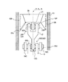
図1は、本実施形態に係るピストン装置及び排熱回収装置であるスターリングエンジンを示す断面図である。図2は、ピストンを支持する気体軸受の説明図である。図3−1、図3−2は、本実施形態に係るスターリングエンジンが備える高温側ピストン及び低温側ピストンが備える給気口の配置例を示す説明図である。まず、本実施形態に係るピストン装置が適用された排熱回収装置であるスターリングエンジンについて説明する。 FIG. 1 is a cross-sectional view showing a Stirling engine that is a piston device and an exhaust heat recovery device according to the present embodiment. FIG. 2 is an explanatory diagram of a gas bearing that supports a piston. FIGS. 3A and 3B are explanatory diagrams illustrating an arrangement example of the air supply ports provided in the high temperature side piston and the low temperature side piston provided in the Stirling engine according to the present embodiment. First, a Stirling engine that is an exhaust heat recovery device to which the piston device according to the present embodiment is applied will be described.
本実施形態に係るピストン装置及び排熱回収装置であるスターリングエンジン1は、いわゆるα型の直列2気筒スターリングエンジンである。そして、第1シリンダである高温側シリンダ15A内に収められた第1ピストンである高温側ピストン20Aと、第2シリンダである低温側シリンダ15B内に収められた第2ピストンである低温側ピストン20Bとが直列に配置されている。
A Stirling engine 1 that is a piston device and an exhaust heat recovery device according to the present embodiment is a so-called α-type in-line two-cylinder Stirling engine. The high
高温側ピストン20Aの内部には、高温側蓄圧室22Aが設けられ、低温側ピストン20Bの内部には、低温側蓄圧室22Bが設けられる。なお、必要に応じて高温側シリンダ15A及び低温側シリンダ15Bはシリンダ15といい、高温側ピストン20A及び低温側ピストン20Bはピストン20といい、高温側蓄圧室22A及び低温側蓄圧室22Bを蓄圧室22という。
A high temperature side
高温側シリンダ15Aと低温側シリンダ15Bとは、基準体である基板3に固定されて支持される。本実施形態に係るスターリングエンジン1においては、この基板3が、スターリングエンジン1の各構成要素の位置基準となる。このように構成することで、前記各構成要素の相対的な位置精度を確保できる。また、後述するように、本実施形態に係るスターリングエンジン1は、高温側シリンダ15Aと高温側ピストン20Aとの間、及び低温側シリンダ15Bと低温側ピストン20Bとの間に気体軸受GBを介在させる。
The high
基準体である基板3に、高温側シリンダ15Aと低温側シリンダ15Bとを直接又は間接的に取り付けることにより、ピストン20とシリンダ15とのクリアランスを精度よく保持することができるので、気体軸受GBの機能を十分に発揮させることができる。さらに、スターリングエンジン1の組み立ても容易になる。また、スターリングエンジン1を排熱回収に用いる場合、この基板3は、スターリングエンジン1を内燃機関の排気通路等へ取り付けるときの基準として使用できるという利点もある。
Since the high
高温側シリンダ15Aと低温側シリンダ15Bとは、ヒータ2Hと再生器2Rとクーラー2Cとで構成される熱交換器2によって接続されている。ここで、ヒータ2Hの一端は高温側シリンダ15Aに接続され、他端は再生器2Rに接続される。ヒータ2Hは、作動流体を加熱する。再生器2Rは、一端がヒータ2Hに接続され他端はクーラー2Cに接続されて、ヒータ2H又はクーラー2Cから流入する作動流体が通過する。クーラー2Cの一端は再生器2Rに接続され、他端は低温側シリンダ15Bに接続される。クーラー2Cは、作動流体を冷却する。高温側シリンダ15A及び低温側シリンダ15Bには、熱交換器2を通過した作動流体が流入し、流出する。
The high
また、高温側シリンダ15A内の高温側作動空間14A、低温側シリンダ15B内の低温側作動空間14B、及び熱交換器2内には作動流体(気体であり、本実施形態では空気)が封入されている。そして、作動流体はヒータ2Hから熱を供給されるとともに、クーラー2Cで熱を排出することによってスターリングサイクルを構成し、高温側ピストン20A、低温側ピストン20Bを駆動する。ここで、例えば、ヒータ2H、クーラー2Cは、熱伝導率が高く耐熱性に優れた材料のチューブを複数束ねた構成とすることができる。また、再生器2Rは、多孔質の蓄熱体で構成することができる。なお、ヒータ2H、クーラー2C及び再生器2Rの構成は、この例に限られるものではなく、排熱回収対象の熱条件やスターリングエンジン1の仕様等によって、好適な構成を選択できる。
A working fluid (a gas, which is air in the present embodiment) is enclosed in the high temperature
高温側ピストン20A及び低温側ピストン20Bは、それぞれ高温側シリンダ15A及び低温側シリンダ15B内に、気体軸受GBを介して支持されている。これによって、潤滑油を用いることなくピストン20とシリンダ15との摩擦を低減して、スターリングエンジン1の正味熱効率を向上させることができる。また、ピストンとシリンダとの摩擦を低減することにより、例えば、内燃機関の排熱を回収する場合のように、低熱源、低温度差の運転条件下においても、スターリングエンジン1を運転して排熱を回収できる。
The high
本実施形態に係る気体軸受GBは、いわゆる静圧気体軸受である。また、本実施形態における気体軸受GBは、往復運動するピストン20をシリンダ15内で支持するものである(以下同様)。すなわち、本実施形態において、気体軸受は、摺動する一対の構造物同士の間に気体が介在して、構造物同士間の摩擦を低減する機能を有するものである(以下同様)。気体軸受GBを構成するため、ピストン20とシリンダ15の内面15iとの隙間tc(図2参照)は、ピストン20の全周にわたって数μm〜数十μmとする。シリンダ15及びピストン20は、例えば、金属材料を用いて構成することができる。
The gas bearing GB according to the present embodiment is a so-called static pressure gas bearing. The gas bearing GB in the present embodiment supports the
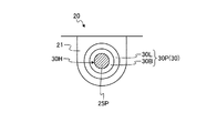
本実施形態においては、図2に示すように、ピストン20の側部(ピストン側部)24に開口する第1の給気口231及び第2の給気口232から、ピストン20内の蓄圧室22の気体(作動流体)が流出する。これによって、シリンダ15とピストン20との間に気体軸受GBを形成する。ここで、ピストン20内の蓄圧室22は、少なくとも、シリンダ15と対向するピストン20の側部24と、側部24に取り付けられる隔壁26とで囲まれる空間である。
In the present embodiment, as shown in FIG. 2, the first
蓄圧室22には、気体供給管17が接続されている。そして、蓄圧室22には、気体軸受用気体供給手段である気体軸受用ポンプ16から気体供給管17を介して気体軸受GBを形成するための気体FLが供給される。気体FLは、本実施形態ではスターリングエンジン1の作動流体と同じ気体であり、具体的には空気である。以下、気体FLを作動流体FLという。
A
図1に示すスターリングエンジン1では、気体軸受用ポンプ16はスターリングエンジン1のクランクケース4の外部に設けられている。そして、この気体軸受用ポンプ16によって、高温側ピストン20Aの高温側蓄圧室22Aには気体供給管17Aから、低温側ピストン20Bの低温側蓄圧室22Bには気体供給管17Bから作動流体FLが供給される。蓄圧室22へ供給された作動流体FLは、第1の給気口231及び第2の給気口232からピストン20の側部24とシリンダ15との間へ流出して、気体軸受GBを形成する。
In the Stirling engine 1 shown in FIG. 1, the
高温側ピストン20A及び低温側ピストン20Bの往復運動は、それぞれ高温側延長ロッド12A、高温側コネクティングロッド13A、及び低温側延長ロッド12B、低温側コネクティングロッド13Bによってクランクシャフト10に伝達され、クランクシャフト10で回転運動に変換される。ここで、クランクシャフト10はクランクシャフト回転軸Xcを中心として回転する。高温側延長ロッド12A、高温側コネクティングロッド13A、低温側延長ロッド12B、低温側コネクティングロッド13Bは、ピストン20とクランクシャフト10との間に設けられて、ピストン20の往復運動をクランクシャフト10に伝達する。
The reciprocating motion of the high
高温側ピストン20Aと高温側延長ロッド12Aとは、ピストン側継ぎ手機構30Pを介して連結され、低温側ピストン20Bと低温側延長ロッド12Bとは、ピストン側継ぎ手機構30Pを介して連結される。また、高温側延長ロッド12Aと高温側コネクティングロッド13Aとは、クランクシャフト側継ぎ手機構30Cを介して連結され、低温側延長ロッド12Bと低温側コネクティングロッド13Bとは、クランクシャフト側継ぎ手機構30Cを介して連結される。ここで、クランクシャフト側継ぎ手機構30Cは、ピストン側継ぎ手機構30Pよりもクランクシャフト10側に配置される。
The high
ここで、高温側延長ロッド12A、低温側延長ロッド12Bを区別しない場合には、延長ロッド12といい、高温側コネクティングロッド13A、低温側コネクティングロッド13Bを区別しない場合には、コネクティングロッド13といい、ピストン側継ぎ手機構30P、クランクシャフト側継ぎ手機構30Cを区別しない場合には、継ぎ手機構30という。
Here, when the high temperature
図1に示すように、クランクシャフト10は、クランクケース4に設けられた軸受9で、回転可能に支持される。なお、クランクケース4は基板3に固定される。このとき、クランクケース4は、高温側シリンダ15A及び低温側シリンダ15Bと独立に、すなわち、これらと接触しないように、基板3に固定される。これにより、高温側シリンダ15A及び低温側シリンダ15Bが受けるクランクシャフト10の振動やクランクシャフト10の熱膨張等の影響を最小限にできるので、気体軸受GBの機能が十分に確保される。
As shown in FIG. 1, the
図1に示すように、スターリングエンジン1を構成する高温側シリンダ15A、高温側ピストン20A、クランクシャフト10等の各構成要素は、筐体5に格納される。筐体5内は、加圧手段11により加圧される。これは、高温側シリンダ15A及び低温側シリンダ15B、及び熱交換器2内の作動流体(本実施形態では気体であり空気)を加圧して、スターリングエンジン1からより多くの出力を取り出すためである。これによって、排熱回収のように低質な熱源しか用いることができない場合でも、より多くの出力をスターリングエンジン1から取り出すことができる。ここで、スターリングエンジン1の出力は、筐体5内に充填される気体の圧力にほぼ比例して大きくなる。
As shown in FIG. 1, the constituent elements such as the high
また、本実施形態に係るスターリングエンジン1では、筐体5にシール軸受6が取り付けられており、出力軸7がシール軸受6により支持される。出力軸7とクランクシャフト10とは、フレキシブルカップリング8を介して連結されており、これを介して筐体5の外部へクランクシャフト10の出力が伝達される。なお、本実施形態において、フレキシブルカップリング8には、オルダムカップリングを使用している。次に、ピストン20が備える給気口の配置を説明する。
In the Stirling engine 1 according to this embodiment, the seal bearing 6 is attached to the
図3−1、図3−2に示すように、本実施形態に係る高温側ピストン20Aでは、第1の給気口231及び第2の給気口232はそれぞれ4個ずつ、計8個設けられる。図3−1に示すように、第1の給気口231は、高温側ピストン20Aの周方向に略等間隔(約90度)で配置される。また、図3−2に示すように、第2の給気口232は、高温側ピストン20Aの周方向に略等間隔(約90度)で、かつ、第1の給気口231とは、約45度ずらして配置される。このように配置することで、気体軸受GBの偏りを低減できる。なお、給気口の数、配置はこの例に限られるものではない。
Figure 3-1, as shown in Figure 3-2, the high
図4は、本実施形態に係るスターリングエンジンに適用できるピストンの他の例を示す説明図である。図4に示すピストン20’は、内部に蓄圧室22が設けられる。すなわち、蓄圧室22は、ピストン20’の外殻、すなわち頂部20t’、側部24’、底部20u’で囲まれる空間である。ピストン20’の頂部20t’には、蓄圧室22と連通する気体導入通路29が設けられる。作動空間14内の作動流体FLは、気体導入通路29を通ってピストン20’の蓄圧室22へ導入される。
FIG. 4 is an explanatory view showing another example of a piston applicable to the Stirling engine according to the present embodiment. The
図4に示すように、気体導入通路29の蓄圧室22側には、蓄圧室22内に導入された作動流体FLの逆流を防止するため、加圧状態保持手段として逆止弁40が設けられる。逆止弁40は、蓄圧室22の内部へ配置され、気体導入通路29から作動空間14内の作動流体FLを蓄圧室22へ導入し、また、蓄圧室22内の作動流体FLが作動空間14内へ逆流することを防止する。
As shown in FIG. 4, a
ピストン20’の動きにより、図4に示すシリンダ15内の作動空間14に存在する作動流体FLの圧力(作動空間内圧力)Pcが上昇し、逆止弁40の開弁圧力に打ち勝ったときに逆止弁40が開弁する。これによって、作動空間14内の作動流体FLが、気体導入通路29を通って蓄圧室22内へ流入する。ここで、逆止弁40の開弁圧力Poは、蓄圧室22内の圧力(蓄圧室内圧力)Ppよりも高い所定の圧力に設定される。
When the pressure of the working fluid FL existing in the working
また、逆止弁40は、ピストン20’の動きにより作動空間内圧力Pcが下がり、蓄圧室内圧力Ppよりも低くなったときには、閉弁する。これによって、蓄圧室22内の作動流体FLが作動空間14へ逆流することを防ぐ。このように、逆止弁40は、蓄圧室22内の加圧状態を保持する加圧状態保持機能を有するとともに、作動流体FLを蓄圧室22内へ導入する作動流体導入機能を有する。蓄圧室22内へ導入された作動流体FLは、ピストン20’の側部24に開口する第1の給気口231及び第2の給気口232から、ピストン20’内の蓄圧室22の作動流体FLが流出する。これによって、シリンダ15とピストン20’との間に気体軸受GBが形成される。次に、本実施形態に係るスターリングエンジン1におけるピストン20の支持構造を説明する。
Further, the
図5は、本実施形態に係るスターリングエンジンが備えるピストンの支持構造を示す説明図である。本実施形態に係るスターリングエンジン1は、気体軸受GBを介してピストン20をシリンダ15内に支持する。気体軸受GBは、ピストン20の直径方向(横方向、スラスト方向)の力に耐える能力(負荷能力)が低いため、ピストン20のサイドフォース(ピストン20の直径方向に向かう力)Fsを実質的にゼロにすることが好ましい。このため、シリンダ15の中心軸(シリンダ中心軸)に対するピストン20の直線運動精度を高くする必要がある。これを実現するため、本実施形態において、ピストン20(高温側ピストン20A及び低温側ピストン20B)は、近似直線機構によって支持される。本実施形態では、近似直線機構として、図5に示すグラスホッパ機構18を用いる。
FIG. 5 is an explanatory view showing a piston support structure provided in the Stirling engine according to the present embodiment. The Stirling engine 1 according to the present embodiment supports the
グラスホッパ機構18は、一端部がスターリングエンジン1の筐体5へ回動可能に取り付けられる第1腕18Aと、同じく一端部がスターリングエンジン1の筐体5へ回動可能に取り付けられる第2腕18Bと、一端部が延長ロッド12とコネクティングロッド13との連結部分へ回動可能に連結され、他端部が第2腕18Bの他端部と回動可能に連結される第3腕18Cとで構成される。また、第1腕18Aの他端部は、第3腕18Cの両端部の間に、回動可能に連結される。このように、連結部材である延長ロッド12とコネクティングロッド13との連結部分は、近似直線機構であるグラスホッパ機構18により支持される。これによって、連結部材12のクランクシャフト側における連結対象、すなわちコネクティングロッド13と連結される部分は、近似直線機構によって支持される。延長ロッド12は、ピストン20と回動可能に連結されているので、ピストン20は、延長ロッド12を介して近似直線機構であるグラスホッパ機構18に支持される。
The
このように構成されるグラスホッパ機構18を用いれば、ピストン20を略直線状に往復運動させることができる。その結果、ピストン20のサイドフォースFsがほとんど0になるので、負荷能力の小さい気体軸受GBによっても十分にピストン20を支持することができる。なお、ピストン20を支持する近似直線機構はグラスホッパ機構18に限られるものではなく、ワットリンク等を用いてもよい。
If the
なお、グラスホッパ機構18は、他の直線近似機構に比べて、同じ直線運動精度を得るために必要な機構の寸法が小さくて済むため、スターリングエンジン1全体がコンパクトになるという利点がある。特に、本実施形態に係るスターリングエンジン1を車両に搭載される内燃機関の排熱回収に用い、内燃機関の排ガスの通路に熱交換器2を配置するというような、限られたスペースにスターリングエンジン1を設置する場合、スターリングエンジン1の全体がコンパクトである方が設置の自由度は向上する。また、グラスホッパ機構18は、同じ直線運動精度を得るために必要な機構の質量が他の機構よりも軽量で済むため、熱効率を向上させる点で有利である。さらに、グラスホッパ機構18は、機構の構成が比較的簡単であるため、製造・組み立てが容易であり、また製造コストも低減できるという利点もある。
The
本実施形態において、ピストン20は、延長ロッド12及びコネクティングロッド13を介してクランクシャフト10と連結される。ピストン20と延長ロッド12との間、及び延長ロッド12とコネクティングロッド13との間には、それぞれ継ぎ手機構30が設けられる。ここで、延長ロッド12は、ピストン20に連結し、かつピストン20とクランクシャフト10との間に設けられる連結部材である。この例において、ピストン20に連結する連結部材である延長ロッド12のクランクシャフト10側の連結対象は、コネクティングロッド13である。
In the present embodiment, the
このように、ピストン20は、延長ロッド12及び延長ロッド12のそれぞれの端部に配置される継ぎ手機構(第1の継ぎ手機構と第2の継ぎ手機構)30を介してコネクティングロッド13と連結される。このような連結構造により、ピストン20の往復運動がクランクシャフト10へ伝達され、クランクシャフト10で回転運動へ変換される。
In this manner, the
図6−1〜図6−3は、本実施形態に係るピストンの連結構造を示す拡大図である。図7は、本実施形態に係るピストンの連結構造を構成する継ぎ手の構成を示す断面図である。図8は、図7に示す継ぎ手の動きを説明するための座標を示す模式図である。図9は、本実施形態に係るピストンの連結構造を構成する延長ロッドの説明図である。図10は、本実施形態に係るピストンの連結構造によって、コネクティングロッドの中心軸とシリンダ中心軸とのずれを許容できることを説明する概念図である。 FIGS. 6-1 to 6-3 are enlarged views showing the piston coupling structure according to the present embodiment. FIG. 7 is a cross-sectional view showing a configuration of a joint constituting the piston coupling structure according to the present embodiment. FIG. 8 is a schematic diagram showing coordinates for explaining the movement of the joint shown in FIG. FIG. 9 is an explanatory diagram of an extension rod that constitutes the piston coupling structure according to the present embodiment. FIG. 10 is a conceptual diagram for explaining that the displacement between the central axis of the connecting rod and the central axis of the cylinder can be allowed by the piston coupling structure according to the present embodiment.
図6−1に示すように、ピストン20は、ピストン20の底部20u、すなわち、ピストン20の延長ロッド12と対向する側(図1、図5に示すクランクシャフト10と対向する側)に、連結部21が設けられる。そして、連結部21と、延長ロッド12のピストン側端部12P(第1の端部)とが、第1の継ぎ手機構であるピストン側継ぎ手機構30Pを介して連結される。また、延長ロッド12のコネクティングロッド側端部(第2の端部)12Cと、コネクティングロッド13とは、第2の継ぎ手機構であるクランクシャフト側継ぎ手機構30Cを介して連結される。
As shown in FIG. 6A, the
本実施形態において、ピストン側継ぎ手機構30P及びクランクシャフト側継ぎ手機構30Cは、球面滑り軸受である。球面滑り軸受は、転がり軸受とは異なり転動体がなく、外輪と内輪とは球面接触をする滑り軸受であり、主として揺動運動、傾斜運動のための滑り軸受であり、滑り面が球面である滑り軸受である。図7に示すように、継ぎ手機構30(ピストン側継ぎ手機構30P及びクランクシャフト側継ぎ手機構30C)は、球面を滑り面として備える内輪30Bと、前記滑り面と接触し、内輪30Bを回転可能に支持する外輪30Lと、で構成される。内輪30Bには軸孔30Hが貫通しており、継ぎ手機構30は、軸孔30Hを介して取付対象に取り付けられる。
In the present embodiment, the piston side
図8に示す座標系は、図7に示す座標系と対応する。図7、図8のZ軸は、図1、図6に示すシリンダ15の中心軸(シリンダ中心軸)であり、X軸は、図1に示すクランクシャフト回転軸Xcと平行な軸である。X軸はZ軸に直交する。すなわち、Z軸(シリンダ中心軸)は、クランクシャフト回転軸Xc及びクランクシャフト回転軸Xcに平行な軸と直交する。
The coordinate system shown in FIG. 8 corresponds to the coordinate system shown in FIG. 7 and 8 is the center axis (cylinder center axis) of the
また、Y軸は、Z軸とX軸とに直交する軸である。すなわち、Y軸は、Z軸(シリンダ中心軸)と、クランクシャフト回転軸Xc及びクランクシャフト回転軸Xcに平行な軸とに直交する。本実施形態において、継ぎ手機構30は、球面滑り軸受で構成されるので、少なくともX軸の周り(図7、図8の矢印Mx方向)、Y軸の周り(図7、図8の矢印My方向)に回動できる。また、継ぎ手機構30は、Z軸の周りにも回動できる。
The Y axis is an axis orthogonal to the Z axis and the X axis. That is, the Y axis is orthogonal to the Z axis (cylinder center axis) and the crankshaft rotation axis Xc and the axis parallel to the crankshaft rotation axis Xc. In the present embodiment, since the
図6−2に示すように、ピストン側継ぎ手機構30Pの外輪30Lは、ピストン20の連結部21に取り付けられる。また、ピストン側継ぎ手機構30Pの内輪30Bに設けられた軸孔30Hには、延長ロッド12のピストン側端部12Pに固定されるピストン側取り付けピン25Pが差し込まれる。これによって、ピストン側継ぎ手機構30Pを介してピストン20の連結部21と、延長ロッド12とが連結される。
As shown in FIG. 6B, the
図6−3に示すように、クランクシャフト側継ぎ手機構30Cの外輪30Lは、延長ロッド12のコネクティングロッド側端部12Cに取り付けられる。また、クランクシャフト側継ぎ手機構30Cの内輪30Bに設けられた軸孔30Hには、延長ロッド12と連結される部分におけるコネクティングロッド13の端部に固定されるコネクティングロッド側取り付けピン25Cが差し込まれる。これによって、クランクシャフト側継ぎ手機構30Cを介して、延長ロッド12と、コネクティングロッド13とが連結される。
As shown in FIG. 6C, the
図6−1に示す状態は、シリンダ中心軸Zと、コネクティングロッド13の中心軸(コネクティングロッド13の長手方向における中心軸)Zcと、延長ロッド12の中心軸(延長ロッド12の長手方向における中心軸、図9参照)Ziとが一致した状態である。組み立て公差等によって、図1に示すクランクシャフト10のクランクシャフト回転軸Xcと平行な方向にコネクティングロッド13がずれると、コネクティングロッド13の中心軸Zcとシリンダ中心軸Zとがずれた状態でピストン20が往復運動する。すると、ピストン20の中心軸とシリンダ中心軸Zcとがずれた状態で、ピストン20が往復運動することになる。
The state shown in FIG. 6A is the cylinder center axis Z, the center axis of the connecting rod 13 (the center axis in the longitudinal direction of the connecting rod 13) Zc, and the center axis of the extension rod 12 (the center in the longitudinal direction of the extension rod 12). Axis, see FIG. 9) Zi matches. When the connecting
本実施形態に係るスターリングエンジン1は、気体軸受GBを介してシリンダ15内にピストン20が支持される。このため、ピストン20の中心軸とシリンダ中心軸Zcとがずれると、ピストン20とシリンダ15とのクリアランスに偏りが生ずる。その結果、図2に示す気体軸受GBの荷重負荷能力にも偏りが発生して、気体軸受GBの荷重負荷能力を有効に利用できない。
In the Stirling engine 1 according to the present embodiment, the
本実施形態では、少なくともクランクシャフト回転軸Xcと平行な軸であるX軸の周り、及びX軸とシリンダ中心軸Zと直交するY軸の周りに回動できる継ぎ手機構30を、ピストン20とコネクティングロッド13との間に2個配置する。すなわち、ピストン20とコネクティングロッド13とを連結する延長ロッド12の両端に継ぎ手機構30がそれぞれ設けられる。
In the present embodiment, the
このような構成により、図10に示すように、コネクティングロッド13がクランクシャフト回転軸Xcと平行な方向にずれた場合には、連結部材である延長ロッド12がシリンダ中心軸Zに対してクランクシャフト回転軸Xcに向かって傾斜した状態でもピストン20の往復運動が可能になる。これによって、ピストン20は、コネクティングロッド13の中心軸Zcとシリンダ中心軸Zとのずれδを保った状態で往復運動できる。その結果、公差等によってコネクティングロッド13がクランクシャフト回転軸Xcと平行な方向にずれた場合であっても、ピストン20の中心軸とシリンダ中心軸Zcとが一致した状態で、ピストン20が往復運動する。
With such a configuration, as shown in FIG. 10, when the connecting
すなわち、コネクティングロッド13がクランクシャフト回転軸Xcと平行な方向にずれた場合、延長ロッド12の両端部に設けられるピストン側継ぎ手機構30P及びクランクシャフト側継ぎ手機構30Cそれぞれを構成する内輪30Bと外輪30Lとは、シリンダ中心軸Zとクランクシャフト回転軸Xcとに直交するY軸の周りを相対的に回動する。これによって、ピストン20の中心軸とシリンダ中心軸Zとにずれが生じた場合でも、クランクシャフト回転軸Xcと平行な方向におけるピストン20の動きが許容される。したがって、シリンダ中心軸Zとピストン20の中心軸とが一致した状態でピストン20は往復運動するので、ピストン20の姿勢が安定する。
That is, when the connecting
すなわち、気体軸受GBの静圧によってピストン20とシリンダ15とのクリアランスを、ピストン20及びシリンダ15の周方向に向かって一定に保つことができるので、気体軸受GBの荷重負荷能力を有効に利用でき、ピストン20の姿勢が安定する。また、ピストン20を支持するグラスホッパ機構18に多少の振動が発生した場合でも、ピストン側継ぎ手機構30P及びクランクシャフト側継ぎ手機構30Cによってピストン20への振動の伝達が抑制される。これによって、ピストン20は安定した姿勢を維持できる。
That is, since the clearance between the
この場合、延長ロッド12の中心軸Ziは、シリンダ中心軸Zに対して傾斜するが(傾斜角はθ)、コネクティングロッド13の中心軸Zcとシリンダ中心軸Zとピストン20の中心軸との平行は維持される。すなわち、延長ロッド12の中心軸Ziとシリンダ中心軸Zとが傾斜した状態でピストン20は往復運動できるが、コネクティングロッド13の中心軸Zcとシリンダ中心軸Zとピストン20の中心軸との平行は維持される。
In this case, the central axis Zi of the
図11は、シリンダ中心軸周りにおけるピストンの回転を説明する模式図である。図11に示すように、本実施形態において、ピストン20は、それぞれの端部にピストン側継ぎ手機構30P、クランクシャフト側継ぎ手機構30Cを設けた延長ロッド12を介してコネクティングロッド13と連結される。上述したようにピストン側継ぎ手機構30P、クランクシャフト側継ぎ手機構30Cは、図7、図8に示すX軸、Y軸、Z軸の周りに回動できる。したがって、図11に示すように、ピストン20は、シリンダ中心軸Zの周り(図11の矢印Mzで示す方向)にも回動できる。
FIG. 11 is a schematic diagram for explaining the rotation of the piston around the cylinder central axis. As shown in FIG. 11, in this embodiment, the
ピストン20がシリンダ中心軸Zの周りに回動すると、ピストン20の連結部21と延長ロッド12のピストン側端部12Pとが接触したり、延長ロッド12のコネクティングロッド側端部12Cとコネクティングロッド13とが接触したりする。その結果、これらの部分に摩耗が発生したり、これらの部分から騒音が発生したりする。本実施形態の変形例では、シリンダ中心軸Z周りにおけるピストン20の回動を抑制することにより、ピストン20の連結部21と延長ロッド12のピストン側端部12Pとの間等における摩耗や騒音の発生を抑制する。
When the
図12〜図14は、本実施形態の変形例に係るピストンの連結構造を示す拡大図である。図12に示すピストンの連結構造においては、ピストン20の連結部21と延長ロッド12(より具体的には延長ロッド12のピストン側端部12P)との間に、回転抑制手段として、突起部12Tを形成する。また、延長ロッド12のコネクティングロッド側端部12Cとコネクティングロッド13との間にも、回転抑制手段として突起部12Tを形成する。なお、回転抑制手段である突起部12Tは、ピストン20の連結部21と延長ロッド12との間と、延長ロッド12とコネクティングロッド13との間と、のうち少なくとも一方に設けることが好ましい。
FIGS. 12-14 is an enlarged view which shows the connection structure of the piston which concerns on the modification of this embodiment. In the piston connection structure shown in FIG. 12, a
ピストン20側において、突起部12Tは、延長ロッド12に形成してもよいし、ピストン20の連結部21に形成してもよい。また、コネクティングロッド13側において、突起部12Tは、延長ロッド12に形成してもよいし、コネクティングロッド13に形成してもよい。突起部12Tは、延長ロッド12やコネクティングロッド13等と一体に形成してもよい。また、図13に示すように、例えば、延長ロッド12のピストン側端部12Pの外側から回転抑制ピン12Tpを打ち込み、これを内側に突出させ、突起部12Tを形成してもよい。
On the
このような構成により、シリンダ中心軸Zの周りにおけるピストン20の回動が抑制される。これによって、ピストン20の連結部21と延長ロッド12のピストン側端部12Pとの接触や、延長ロッド12のコネクティングロッド側端部12Cとコネクティングロッド13との接触を抑制できる。その結果、これらの部分に発生する摩耗や、これらの部分から発生する騒音を抑制できる。特に、図1に示すスターリングエンジン1は騒音が小さいので、ピストン20の連結部21と延長ロッド12のピストン側端部12Pとの接触等による騒音を抑制すると、スターリングエンジン1全体の騒音低下に効果的である。
With such a configuration, the rotation of the
図14に示すピストンの連結構造においては、ピストン20の連結部21と延長ロッド12(より具体的には延長ロッド12のピストン側端部12P)との間に、回転抑制手段として緩衝材32を設ける。また、延長ロッド12のコネクティングロッド側端部12Cとコネクティングロッド13との間にも、回転抑制手段として緩衝材32を設ける。緩衝材32は、弾性部材が好ましく、例えば、樹脂、スポンジ、ウレタン、フェルト等が使用できる。
In the piston coupling structure shown in FIG. 14, a
このような構成により、シリンダ中心軸Zの周りにおけるピストン20の回動が抑制される。これによって、ピストン20の連結部21と延長ロッド12のピストン側端部12Pとの接触や、延長ロッド12のコネクティングロッド側端部12Cとコネクティングロッド13との接触を抑制できる。また、これらの部分において二つの部材に接触が発生した場合でも、緩衝材32によって接触時における衝撃を緩和できる。その結果、これらの部分に発生する摩耗や、これらの部分から発生する騒音をより効果的に抑制できる。また、緩衝材32によって、ピストン20の連結部21や延長ロッド12のコネクティングロッド側端部12Cを挟持するので、ピストン20の姿勢安定性にも効果的である。
With such a configuration, the rotation of the
図15は、本実施形態の変形例に係るピストンの連結構造を示す模式図である。このピストンの連結構造は、ピストン20とクランクシャフト10とを、直接コネクティングロッド13aで連結する。この場合、コネクティングロッド13aが、ピストン20とクランクシャフト10との間に設けられて、ピストン20に連結される連結部材となる。この例において、ピストン20に連結する連結部材である延長ロッド12のクランクシャフト10側の連結対象は、クランクシャフト10である。
FIG. 15 is a schematic diagram showing a piston coupling structure according to a modification of the present embodiment. In this piston connection structure, the
コネクティングロッド13aのピストン側端部(第1の端部)には、第1の継ぎ手構造として、ピストン側継ぎ手機構30Pが設けられる。また、コネクティングロッド13aのクランクシャフト側端部(第2の端部)には、第2の継ぎ手構造として、クランクシャフト側継ぎ手機構30Cが設けられる。ピストン側継ぎ手機構30Pの内輪30Bはコネクティングロッド13aに取り付けられ、外輪30Lはピストン20の連結部21に取り付けられる。また、クランクシャフト側継ぎ手機構30Cの内輪30Bはクランクシャフト10に取り付けられ、外輪30Lはコネクティングロッド13aに取り付けられる。このような構成により、コネクティングロッド13aは、ピストン側継ぎ手機構30Pを介してピストン20に取り付けられ、また、クランクシャフト側継ぎ手機構30Cを介してクランクシャフト10に取り付けられる。
A piston-side
このピストンの支持構造においても、少なくともクランクシャフト10の回転軸と平行な軸であるX軸の周り、及びX軸とシリンダ中心軸Zと直交するY軸の周りに回動できる継ぎ手機構30を、ピストン20とコネクティングロッド13aとの間に2個配置する。すなわち、ピストン20とクランクシャフト10とを連結するコネクティングロッド13aの両端に継ぎ手機構30がそれぞれ設けられる。このような構成により、コネクティングロッド13aがクランクシャフトの回転軸と平行な方向にずれた場合には、シリンダ中心軸Zに対しクランクシャフト10の回転軸と平行な方向に向かってコネクティングロッド13aが傾斜した状態で、ピストン20がシリンダ15内を往復運動できる。これによって、公差等によってコネクティングロッド13aがクランクシャフト10の回転軸と平行な方向にずれた場合であっても、ピストン20の中心軸とシリンダ中心軸Zcとが一致した状態で、ピストン20が往復運動する。
Also in this piston support structure, the
すなわち、コネクティングロッド13aがクランクシャフト10の回転軸と平行な方向にずれた場合、コネクティングロッド13aの両端部に設けられるピストン側継ぎ手機構30P及びクランクシャフト側継ぎ手機構30Cそれぞれを構成する内輪30Bと外輪30Lとは、シリンダ中心軸Zとクランクシャフト10の回転軸とに直交するY軸の周りを相対的に回動する。これによって、ピストン20の中心軸とシリンダ中心軸Zとにずれが生じた場合でも、クランクシャフト10の回転軸方向におけるピストン20の動きが許容される。
That is, when the connecting
したがって、ピストン20自身が気体軸受GBの静圧によってシリンダ15とのクリアランスを一定に保つことができるので、ピストン20の姿勢が安定する。すなわち、シリンダ中心軸Zとピストン20の中心軸とが一致した状態でピストン20は往復運動するので、気体軸受GBの荷重負荷能力を有効に利用できる。
Therefore, since the
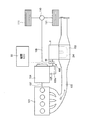
図16は、本実施形態に係るスターリングエンジンを内燃機関の排熱回収に用いる場合の構成例を示す模式図である。本実施形態では、スターリングエンジン1の出力を、スターリングエンジン用変速機105を介して内燃機関用変速機104へ入力し、内燃機関101の出力と合成して取り出す。
FIG. 16 is a schematic diagram illustrating a configuration example when the Stirling engine according to the present embodiment is used for exhaust heat recovery of an internal combustion engine. In the present embodiment, the output of the Stirling engine 1 is input to the internal
本実施形態において、内燃機関101は、例えば、乗用車やトラック等の車両に搭載されて、前記車両の動力源となる。内燃機関101は、前記車両の走行中においては主たる動力源として出力を発生する。一方、スターリングエンジン1は、排ガスExの温度がある程度の温度にならないと、必要最低限の出力を生み出すことができない。したがって、本実施形態において、スターリングエンジン1は、内燃機関101の排出する排ガスExの温度が所定温度を超えたら内燃機関101の排ガスExから熱エネルギーを回収して出力を発生し、内燃機関101とともに前記車両を駆動する。このように、スターリングエンジン1は、前記車両の従たる動力源となる。
In the present embodiment, the
スターリングエンジン1が備えるヒータ2Hは、内燃機関101の排気通路102内に配置される。なお、排気通路102内には、図1に示すスターリングエンジン1の再生器2Rを配置してもよい。スターリングエンジン1が備えるヒータ2Hは、排気通路102に設けられる中空のヒータケース103内に設けられる。
The
本実施形態において、スターリングエンジン1を用いて回収した排ガスExの熱エネルギーは、スターリングエンジン1で運動エネルギーに変換される。スターリングエンジン1の出力軸であるクランクシャフト110には、動力断続手段であるクラッチ106が取り付けられており、スターリングエンジン1の出力は、クラッチ106を介してスターリングエンジン用変速機105に伝達される。
In the present embodiment, the thermal energy of the exhaust gas Ex recovered using the Stirling engine 1 is converted into kinetic energy by the Stirling engine 1. The
内燃機関101の出力は、内燃機関101の出力軸107を介して内燃機関用変速機104に入力される。そして、内燃機関用変速機104は、内燃機関101の出力と、スターリングエンジン用変速機105から出力されるスターリングエンジン1の出力とを合成して、変速機出力軸109に出力し、デファレンシャルギヤ110を介して駆動輪111を駆動する。
The output of the
ここで、動力断続手段であるクラッチ106は、内燃機関用変速機104とスターリングエンジン1との間に設けられる。本実施形態では、スターリングエンジン用変速機105の入力軸105sとスターリングエンジン1のクランクシャフト110との間に設けられる。クラッチ106は、係合、解放することによって、スターリングエンジン1のクランクシャフト110と、スターリングエンジン用変速機105の入力軸105sとの機械的な接続を断続する。ここで、クラッチ106は、機関ECU50によって制御される。
Here, the clutch 106 serving as the power interrupting means is provided between the internal
スターリングエンジン1は、内燃機関101の排出する排ガスExの熱エネルギーを回収するため、内燃機関101の冷間始動時等のように排ガスExの温度が低い場合には、排ガスExから熱エネルギーを回収できず、出力を発生することができない。このため、スターリングエンジン1が出力を発生できるようになるまではクラッチ106を解放して、スターリングエンジン1と内燃機関101とを切り離して、スターリングエンジン1が内燃機関101に駆動されることによるエネルギー損失を抑制する。
Since the Stirling engine 1 recovers the thermal energy of the exhaust gas Ex discharged from the
クラッチ106を係合すると、スターリングエンジン1のクランクシャフト110と内燃機関101の出力軸107とは、スターリングエンジン用変速機105及び内燃機関用変速機104を介して直結される。これによって、スターリングエンジン1の発生する出力と内燃機関101の発生する出力とは、内燃機関用変速機104で合成され、変速機出力軸109から取り出される。一方、クラッチ106を開放すると、内燃機関101の出力軸107はスターリングエンジン1のクランクシャフト110と切り離されて回転する。
When the clutch 106 is engaged, the
図16に示す本実施形態のスターリングエンジン1が備えるピストンは、上述した構成により安定した運転が確保できる。また、車両に搭載されるスターリングエンジン1が振動を受けた場合でも、ピストンの姿勢が安定しているため、ピストンとシリンダとのクリアランスを一定に維持して、気体軸受の荷重負荷能力を十分に発揮させることができる。また、ピストンの連結部と延長ロッドとの間等に、シリンダ中心軸周りにおけるピストンの回転を抑制する回転抑制手段を設けるので、騒音の発生を抑制できる。これによって、スターリングエンジン1の静粛性を確保できる。また、前記回転抑制手段により、ピストンの連結部と延長ロッドとの接触等を抑制して、両者の摩耗を抑制できるので、スターリングエンジン1の耐久性低下を抑制できる。 The piston provided in the Stirling engine 1 of this embodiment shown in FIG. 16 can ensure stable operation by the above-described configuration. Further, even when the Stirling engine 1 mounted on the vehicle is subjected to vibration, since the posture of the piston is stable, the clearance between the piston and the cylinder is kept constant, and the load capacity of the gas bearing is sufficiently increased. It can be demonstrated. Moreover, since the rotation suppression means for suppressing the rotation of the piston around the cylinder center axis is provided between the connecting portion of the piston and the extension rod, the generation of noise can be suppressed. Thereby, the silence of the Stirling engine 1 can be ensured. In addition, since the rotation suppressing means can suppress contact between the connecting portion of the piston and the extension rod and suppress wear of both, it is possible to suppress a decrease in durability of the Stirling engine 1.
以上、本実施形態では、シリンダ内を往復運動するピストンに連結し、かつ前記ピストンとクランクシャフトとの間に設けられる連結部材が、前記シリンダの中心軸に対し前記クランクシャフトの回転軸と平行な方向に向かって傾斜した状態でも、前記ピストンが前記シリンダ内を往復運動可能となるように構成する。これによって、公差等に起因する、クランクシャフトの回転軸と平行な方向におけるピストンの中心軸とシリンダ中心軸とのずれを吸収して、ピストンの中心軸とシリンダ中心軸とを一致させた状態でピストンが往復運動する。その結果、ピストンとシリンダとの間に介在する気体軸受の機能を荷重不可能力を確実に発揮させることができるので、ピストンとシリンダとを接触させないことを前提とするピストン機関においても、安定して運転できる。 As described above, in this embodiment, the connecting member connected to the piston that reciprocates in the cylinder and provided between the piston and the crankshaft is parallel to the rotation axis of the crankshaft with respect to the center axis of the cylinder. The piston is configured to be able to reciprocate in the cylinder even in a state inclined toward the direction. This absorbs the deviation between the central axis of the piston and the cylinder central axis in the direction parallel to the rotation axis of the crankshaft due to tolerances, etc., so that the piston central axis and the cylinder central axis are aligned. The piston reciprocates. As a result, the function of the gas bearing interposed between the piston and the cylinder can be surely exerted the non-loadable force, so that even in a piston engine that presupposes that the piston and the cylinder do not come into contact with each other stably I can drive.
また、例えば、ピストンと連結部材との連結部や、連結部材とコネクティングロッドとの連結部にボールジョイントを用いる場合、ボールの中心と一致した中心軸を持つシャフトをボールジョイントのソケットの両端へ新たに設ける必要があり、構造が複雑になる。これによって、ピストンの連結構造が大型化するとともに複雑化し、摺動部が増加することにより摩擦も増加する。本実施形態では、少なくとも2軸の周りを回動可能な継ぎ手構造として球面滑り軸受を用い、ピストンとクランクシャフトとの間に設けられる連結部材の両端部に第1の継ぎ手機構及び第2の継ぎ手機構として、それぞれ球面滑り軸受を設ける。これによって、ピストンとコネクティングロッドとを、1本の部材及び2個の継ぎ手機構で連結できる。その結果、自由度の高いピストンとクランクシャフトとの連結構造を簡易かつコンパクトに構成できる。 For example, when a ball joint is used for the connecting portion between the piston and the connecting member or the connecting portion between the connecting member and the connecting rod, a shaft having a central axis that coincides with the center of the ball is newly added to both ends of the socket of the ball joint. Therefore, the structure becomes complicated. As a result, the connecting structure of the piston increases in size and complexity, and the friction increases as the sliding portion increases. In this embodiment, a spherical plain bearing is used as a joint structure that can rotate around at least two axes, and a first joint mechanism and a second joint are provided at both ends of a connecting member provided between the piston and the crankshaft. A spherical plain bearing is provided for each mechanism. As a result, the piston and the connecting rod can be connected by one member and two joint mechanisms. As a result, a highly flexible coupling structure between the piston and the crankshaft can be configured simply and compactly.
以上のように、本発明に係るピストン機関は、ピストンリングを用いないピストン機関に有用であり、特に、ピストンとシリンダとの間に気体軸受を介在させるピストン機関に適している。 As described above, the piston engine according to the present invention is useful for a piston engine that does not use a piston ring, and is particularly suitable for a piston engine in which a gas bearing is interposed between a piston and a cylinder.
1 スターリングエンジン
2 熱交換器
2C クーラー
2H ヒータ
2R 再生器
4 クランクケース
5 筐体
10 クランクシャフト
11 加圧手段
12 延長ロッド
12A 高温側延長ロッド
12B 低温側延長ロッド
12C コネクティングロッド側端部
12P ピストン側端部
12Tp 回転抑制ピン
12T 突起部
13、13a コネクティングロッド
13A 高温側コネクティングロッド
13B 低温側コネクティングロッド
14 作動空間
14A 高温側作動空間
14B 低温側作動空間
15 シリンダ
15A 高温側シリンダ
15B 低温側シリンダ
16 気体軸受用ポンプ
17 気体供給管
18 グラスホッパ機構
18A 第1腕
18B 第2腕
18C 第3腕
20 ピストン
20A 高温側ピストン
20B 低温側ピストン
20t 頂部
20u 底部
21 連結部
22 蓄圧室
22A 高温側蓄圧室
22B 低温側蓄圧室
231、232 給気口
24、24’ 側部
25P ピストン側取り付けピン
25C コネクティングロッド側取り付けピン
29 気体導入通路
30 継ぎ手機構
30B 内輪
30L 外輪
30H 軸孔
30P ピストン側継ぎ手機構
30C クランクシャフト側継ぎ手機構
32 緩衝材
40 逆止弁
DESCRIPTION OF SYMBOLS 1 Stirling engine 2
Claims (10)
前記ピストンに連結し、かつ前記ピストンと前記クランクシャフトとの間に設けられる連結部材が、少なくとも前記シリンダの中心軸に対し前記クランクシャフトの回転軸と平行な方向に向かって傾斜した状態でも、前記ピストンが前記シリンダ内を往復運動可能となるように、
前記ピストンと前記連結部材の第1の端部とを連結するとともに、前記ピストンと前記連結部材の前記第1の端部とが、互いに、前記シリンダの中心軸周りと、前記クランク軸の回転軸に平行な軸周りと、前記クランクシャフトの回転軸と前記シリンダの中心軸とに直交する軸周りに回動することを許容する第1の継ぎ手機構と、
前記連結部材の第2の端部と前記クランクシャフト側の連結対象とを連結するとともに、前記連結部材の前記第2の端部と前記クランクシャフト側の連結対象とが、互いに、前記シリンダの中心軸周りと、前記クランク軸の回転軸に平行な軸周りと、前記クランクシャフトの回転軸と前記シリンダの中心軸とに直交する軸周りに回動することを許容する第2の継ぎ手機構と、を備え、更に、
前記ピストンと前記連結部材との間における前記シリンダの中心軸周りの回転と、前記連結対象と前記連結部材との間における前記シリンダの中心軸周りの回転と、のうち少なくとも一方を抑制する回転抑制手段としての突起部を、前記ピストンと前記連結部材の前記第1の端部とのうちのいずれか一方、または、前記連結対象と前記連結部材の前記第2の端部とのうちのいずれか一方に備えることを特徴とするピストン機関。 A piston that reciprocates in a cylinder, and a crankshaft that converts the reciprocating motion of the piston into rotational motion,
Even in a state where the connecting member connected to the piston and provided between the piston and the crankshaft is inclined toward at least a direction parallel to the rotation axis of the crankshaft with respect to the central axis of the cylinder, So that the piston can reciprocate in the cylinder ,
The piston and the first end of the connecting member are connected, and the piston and the first end of the connecting member are mutually connected around the center axis of the cylinder and the rotation shaft of the crankshaft. A first joint mechanism that allows rotation about an axis parallel to the rotation axis and an axis orthogonal to a rotation axis of the crankshaft and a central axis of the cylinder;
The second end of the connecting member and the connection object on the crankshaft side are connected, and the second end of the connection member and the connection object on the crankshaft side are connected to each other in the center of the cylinder. A second joint mechanism allowing rotation around an axis, around an axis parallel to the rotation axis of the crankshaft, and around an axis orthogonal to the rotation axis of the crankshaft and the central axis of the cylinder; In addition,
Rotation suppression that suppresses at least one of rotation around the central axis of the cylinder between the piston and the connecting member and rotation around the central axis of the cylinder between the connection target and the connecting member. The protrusion as a means is either one of the piston and the first end of the connecting member, or one of the connection target and the second end of the connecting member. A piston engine provided on one side.
前記ピストンの往復運動を回転運動に変換するクランクシャフトと、
第1の端部が前記ピストンに連結するとともに、第2の端部が前記クランクシャフト側の連結対象に連結する連結部材と、
前記ピストンと前記連結部材の前記第1の端部とを連結するとともに、前記ピストンと前記連結部材の前記第1の端部とが、互いに、前記シリンダの中心軸周りと、前記クランク軸の回転軸に平行な軸周りと、前記クランクシャフトの回転軸と前記シリンダの中心軸とに直交する軸周りに回動することを許容する第1の継ぎ手機構と、
前記連結部材の前記第2の端部と前記クランクシャフト側の連結対象とを連結するとともに、前記連結部材の前記第2の端部と前記クランクシャフト側の連結対象とが、互いに、前記シリンダの中心軸周りと、前記クランク軸の回転軸に平行な軸周りと、前記クランクシャフトの回転軸と前記シリンダの中心軸とに直交する軸周りに回動することを許容する第2の継ぎ手機構と、を備え、更に、
前記ピストンと前記連結部材との間における前記シリンダの中心軸周りの回転と、前記連結対象と前記連結部材との間における前記シリンダの中心軸周りの回転と、のうち少なくとも一方を抑制する回転抑制手段としての突起部を、前記ピストンと前記連結部材の前記第1の端部とのうちのいずれか一方、または、前記連結対象と前記連結部材の前記第2の端部とのうちのいずれか一方に備えることを特徴とするピストン機関。 A piston that reciprocates in the cylinder;
A crankshaft for converting the reciprocating motion of the piston into a rotational motion;
A first end portion connected to the piston, and a second end portion connected to the crankshaft side connection object;
The piston and the first end of the connecting member are connected to each other, and the piston and the first end of the connecting member are rotated around the center axis of the cylinder and the rotation of the crankshaft. A first joint mechanism allowing rotation around an axis parallel to the axis, and an axis orthogonal to a rotation axis of the crankshaft and a central axis of the cylinder ;
The second end portion of the connecting member and the connection target on the crankshaft side are connected to each other, and the second end portion of the connection member and the connection target on the crankshaft side are connected to each other of the cylinder. A second joint mechanism allowing rotation around a central axis, around an axis parallel to the rotation axis of the crankshaft, and around an axis orthogonal to the rotation axis of the crankshaft and the central axis of the cylinder ; In addition,
Rotation suppression that suppresses at least one of rotation around the central axis of the cylinder between the piston and the connecting member and rotation around the central axis of the cylinder between the connection target and the connecting member. The protrusion as a means is either one of the piston and the first end of the connecting member, or one of the connection target and the second end of the connecting member. A piston engine provided on one side.
前記熱交換器を通過した作動流体が流入し、流出するシリンダと、
前記シリンダ内を往復運動するとともに、内部に蓄圧室が形成されるピストンと、
前記ピストンの側部に設けられ、前記蓄圧室内の気体を前記ピストンと前記シリンダとの間に流出させる給気口と、
前記ピストンの往復運動を回転運動に変換するクランクシャフトと、
前記ピストンの往復運動を前記クランクシャフトへ伝達するコネクティングロッドと、
第1の端部が前記ピストンに連結するとともに、第2の端部が前記コネクティングロッドに連結する連結部材と、
前記連結部材と前記コネクティングロッドとの連結部分を支持する近似直線機構と、
前記ピストンと前記連結部材の前記第1の端部とを連結するとともに、前記ピストンと前記連結部材の前記第1の端部とが、互いに、前記シリンダの中心軸周りと、前記クランク軸の回転軸に平行な軸周りと、前記クランクシャフトの回転軸と前記シリンダの中心軸とに直交する軸周りに回動することを許容する第1の継ぎ手機構と、
前記連結部材の前記第2の端部と前記クランクシャフト側の連結対象とを連結するとともに、前記連結部材の前記第2の端部と前記クランクシャフト側の連結対象とが、互いに、前記シリンダの中心軸周りと、前記クランク軸の回転軸に平行な軸周りと、前記クランクシャフトの回転軸と前記シリンダの中心軸とに直交する軸周りに回動することを許容する第2の継ぎ手機構と、を備え、更に、
前記ピストンと前記連結部材との間における前記シリンダの中心軸周りの回転と、前記連結対象と前記連結部材との間における前記シリンダの中心軸周りの回転と、のうち少なくとも一方を抑制する回転抑制手段としての突起部を、前記ピストンと前記連結部材の前記第1の端部とのうちのいずれか一方、または、前記連結対象と前記連結部材の前記第2の端部とのうちのいずれか一方に備えることを特徴とするスターリングエンジン。 A heat exchanger comprising: a heater that heats the working fluid; a regenerator that is connected to the heater and through which the working fluid passes; and a cooler that is connected to the regenerator and cools the working fluid. When,
A cylinder into which the working fluid that has passed through the heat exchanger flows in and out;
A reciprocating motion in the cylinder, and a piston in which a pressure accumulating chamber is formed;
An air supply port that is provided on a side of the piston and allows the gas in the pressure accumulation chamber to flow out between the piston and the cylinder;
A crankshaft for converting the reciprocating motion of the piston into a rotational motion;
A connecting rod for transmitting the reciprocating motion of the piston to the crankshaft;
A first end connected to the piston and a second end connected to the connecting rod;
An approximate linear mechanism that supports a connecting portion between the connecting member and the connecting rod;
The piston and the first end of the connecting member are connected to each other, and the piston and the first end of the connecting member are rotated around the center axis of the cylinder and the rotation of the crankshaft. A first joint mechanism allowing rotation around an axis parallel to the axis, and an axis orthogonal to a rotation axis of the crankshaft and a central axis of the cylinder ;
The second end portion of the connecting member and the connection target on the crankshaft side are connected to each other, and the second end portion of the connection member and the connection target on the crankshaft side are connected to each other of the cylinder. A second joint mechanism allowing rotation around a central axis, around an axis parallel to the rotation axis of the crankshaft, and around an axis orthogonal to the rotation axis of the crankshaft and the central axis of the cylinder ; In addition,
Rotation suppression that suppresses at least one of rotation around the central axis of the cylinder between the piston and the connecting member and rotation around the central axis of the cylinder between the connection target and the connecting member. The protrusion as a means is either one of the piston and the first end of the connecting member, or one of the connection target and the second end of the connecting member. A Stirling engine characterized by being provided on one side.
前記熱交換器を通過した作動流体が流入し、流出するシリンダと、
前記シリンダ内を往復運動するとともに、内部に蓄圧室が形成されるピストンと、
前記ピストンの側部に設けられ、前記蓄圧室内の気体を前記ピストンと前記シリンダとの間に流出させる給気口と、
前記ピストンの往復運動を回転運動に変換するクランクシャフトと、
前記ピストンの往復運動を前記クランクシャフトへ伝達するコネクティングロッドと、
第1の端部が前記ピストンに連結するとともに、第2の端部が前記コネクティングロッドに連結する連結部材と、
前記連結部材と前記コネクティングロッドとの連結部分を支持する近似直線機構と、
前記ピストンと前記連結部材の前記第1の端部とを連結するとともに、前記ピストンと前記連結部材の前記第1の端部とが、互いに、前記シリンダの中心軸周りと、前記クランク軸の回転軸に平行な軸周りと、前記クランクシャフトの回転軸と前記シリンダの中心軸とに直交する軸周りに回動することを許容する第1の継ぎ手機構と、
前記連結部材の前記第2の端部と前記クランクシャフト側の連結対象とを連結するとともに、前記連結部材の前記第2の端部と前記クランクシャフト側の連結対象とが、互いに、前記シリンダの中心軸周りと、前記クランク軸の回転軸に平行な軸周りと、前記クランクシャフトの回転軸と前記シリンダの中心軸とに直交する軸周りに回動することを許容する第2の継ぎ手機構と、を備え、更に、
前記ピストンと前記連結部材との間における前記シリンダの中心軸周りの回転と、前記連結対象と前記連結部材との間における前記シリンダの中心軸周りの回転と、のうち少なくとも一方を抑制する回転抑制手段を、前記ピストンと前記連結部材の前記第1の端部とのうちのいずれか一方、または、前記連結対象と前記連結部材の前記第2の端部とのうちのいずれか一方に備え、
前記回転抑制手段は、前記連結部材が連結対象と接触する際の衝撃を緩和する緩衝材であることを特徴とするスターリングエンジン。 A heat exchanger comprising: a heater that heats the working fluid; a regenerator that is connected to the heater and through which the working fluid passes; and a cooler that is connected to the regenerator and cools the working fluid. When,
A cylinder into which the working fluid that has passed through the heat exchanger flows in and out;
A reciprocating motion in the cylinder, and a piston in which a pressure accumulating chamber is formed;
An air supply port that is provided on a side of the piston and allows the gas in the pressure accumulation chamber to flow out between the piston and the cylinder;
A crankshaft for converting the reciprocating motion of the piston into a rotational motion;
A connecting rod for transmitting the reciprocating motion of the piston to the crankshaft;
A first end connected to the piston and a second end connected to the connecting rod;
An approximate linear mechanism that supports a connecting portion between the connecting member and the connecting rod;
The piston and the first end of the connecting member are connected to each other, and the piston and the first end of the connecting member are rotated around the center axis of the cylinder and the rotation of the crankshaft. A first joint mechanism allowing rotation around an axis parallel to the axis, and an axis orthogonal to a rotation axis of the crankshaft and a central axis of the cylinder ;
The second end portion of the connecting member and the connection target on the crankshaft side are connected to each other, and the second end portion of the connection member and the connection target on the crankshaft side are connected to each other of the cylinder. A second joint mechanism allowing rotation around a central axis, around an axis parallel to the rotation axis of the crankshaft, and around an axis orthogonal to the rotation axis of the crankshaft and the central axis of the cylinder ; In addition,
Rotation suppression that suppresses at least one of rotation around the central axis of the cylinder between the piston and the connecting member and rotation around the central axis of the cylinder between the connection target and the connecting member. A means is provided in any one of the piston and the first end of the connecting member, or in one of the connection object and the second end of the connecting member ,
The Stirling engine according to claim 1, wherein the rotation suppressing means is a shock absorbing material that reduces an impact when the connecting member comes into contact with a connection target.
Priority Applications (5)
| Application Number | Priority Date | Filing Date | Title |
|---|---|---|---|
| JP2007220141A JP4803140B2 (en) | 2007-08-27 | 2007-08-27 | Piston engine and Stirling engine |
| EP08792736.4A EP2184479B1 (en) | 2007-08-27 | 2008-08-26 | Piston engine and stirling engine |
| CN2008801046289A CN101790634B (en) | 2007-08-27 | 2008-08-26 | Piston engine and stirling engine |
| PCT/JP2008/065190 WO2009028498A1 (en) | 2007-08-27 | 2008-08-26 | Piston engine and stirling engine |
| US12/673,133 US20100199944A1 (en) | 2007-08-27 | 2008-08-26 | Piston engine and stirling engine |
Applications Claiming Priority (1)
| Application Number | Priority Date | Filing Date | Title |
|---|---|---|---|
| JP2007220141A JP4803140B2 (en) | 2007-08-27 | 2007-08-27 | Piston engine and Stirling engine |
Publications (2)
| Publication Number | Publication Date |
|---|---|
| JP2009052479A JP2009052479A (en) | 2009-03-12 |
| JP4803140B2 true JP4803140B2 (en) | 2011-10-26 |
Family
ID=40387217
Family Applications (1)
| Application Number | Title | Priority Date | Filing Date |
|---|---|---|---|
| JP2007220141A Expired - Fee Related JP4803140B2 (en) | 2007-08-27 | 2007-08-27 | Piston engine and Stirling engine |
Country Status (5)
| Country | Link |
|---|---|
| US (1) | US20100199944A1 (en) |
| EP (1) | EP2184479B1 (en) |
| JP (1) | JP4803140B2 (en) |
| CN (1) | CN101790634B (en) |
| WO (1) | WO2009028498A1 (en) |
Families Citing this family (11)
| Publication number | Priority date | Publication date | Assignee | Title |
|---|---|---|---|---|
| IT1394021B1 (en) * | 2009-05-08 | 2012-05-25 | Ima Life Srl | DOSING SYSTEM WITH JOINTED MEANS |
| DE112010005625T5 (en) * | 2010-06-01 | 2013-03-21 | Toyota Jidosha Kabushiki Kaisha | Gas lubrication structure of a Stirling engine |
| US8844494B2 (en) * | 2011-02-11 | 2014-09-30 | Ecomotors, Inc. | Pullrod connection to a journal |
| JP5569463B2 (en) * | 2011-05-16 | 2014-08-13 | トヨタ自動車株式会社 | Stirling engine |
| CN103541882B (en) * | 2012-07-12 | 2016-05-11 | 珠海格力节能环保制冷技术研究中心有限公司 | Compression assembly and applied compressor thereof |
| CN103216517B (en) * | 2012-09-26 | 2015-08-19 | 祥天控股(集团)有限公司 | The linkage mechanism of motor |
| MX2015013251A (en) * | 2013-03-15 | 2016-06-07 | New Power Concepts Llc | Stirling cycle machine. |
| CN104806376A (en) * | 2015-04-17 | 2015-07-29 | 合肥工业大学 | Beta-type Stirling engine with three-crank crankshaft for magnetic driving |
| CN109720221A (en) * | 2018-12-28 | 2019-05-07 | 上海重塑能源科技有限公司 | Supporting structure |
| WO2020242845A1 (en) * | 2019-05-21 | 2020-12-03 | General Electric Company | Monolithic heater bodies |
| CN115215178B (en) * | 2022-07-18 | 2024-06-21 | 张文英 | Corridor elevator and conversion method thereof |
Family Cites Families (13)
| Publication number | Priority date | Publication date | Assignee | Title |
|---|---|---|---|---|
| US1612047A (en) * | 1925-09-25 | 1926-12-28 | Dabney P Owens | Piston mounting |
| JPS6140451A (en) * | 1984-07-31 | 1986-02-26 | Mitsubishi Electric Corp | Stirling engine |
| JPH0335319U (en) * | 1989-08-11 | 1991-04-05 | ||
| JPH03153912A (en) * | 1989-11-13 | 1991-07-01 | Hitachi Ltd | Piston device |
| US5094195A (en) * | 1990-04-20 | 1992-03-10 | The Cessna Aircraft Company | Axial cylinder internal combustion engine |
| JP3783706B2 (en) | 2003-10-01 | 2006-06-07 | トヨタ自動車株式会社 | Stirling engine and hybrid system including the same |
| JP3783705B2 (en) * | 2003-10-01 | 2006-06-07 | トヨタ自動車株式会社 | Stirling engine and hybrid system using the same |
| JP3788453B2 (en) * | 2003-10-01 | 2006-06-21 | トヨタ自動車株式会社 | Waste heat recovery device |
| US7367305B2 (en) * | 2003-11-07 | 2008-05-06 | Honda Motor Co., Ltd. | Internal combustion engine and connecting rod therefor |
| JP4228918B2 (en) * | 2004-01-08 | 2009-02-25 | トヨタ自動車株式会社 | Exhaust heat recovery device |
| JP4059248B2 (en) * | 2004-12-27 | 2008-03-12 | トヨタ自動車株式会社 | Piston device, Stirling engine |
| JP4315128B2 (en) * | 2005-06-15 | 2009-08-19 | トヨタ自動車株式会社 | Piston and piston device |
| JP2007231858A (en) * | 2006-03-01 | 2007-09-13 | Toyota Motor Corp | Exhaust heat recovery system |
-
2007
- 2007-08-27 JP JP2007220141A patent/JP4803140B2/en not_active Expired - Fee Related
-
2008
- 2008-08-26 EP EP08792736.4A patent/EP2184479B1/en not_active Not-in-force
- 2008-08-26 US US12/673,133 patent/US20100199944A1/en not_active Abandoned
- 2008-08-26 WO PCT/JP2008/065190 patent/WO2009028498A1/en active Application Filing
- 2008-08-26 CN CN2008801046289A patent/CN101790634B/en not_active Expired - Fee Related
Also Published As
| Publication number | Publication date |
|---|---|
| US20100199944A1 (en) | 2010-08-12 |
| EP2184479A4 (en) | 2014-04-09 |
| CN101790634B (en) | 2013-03-06 |
| WO2009028498A1 (en) | 2009-03-05 |
| EP2184479A1 (en) | 2010-05-12 |
| EP2184479B1 (en) | 2015-10-14 |
| JP2009052479A (en) | 2009-03-12 |
| CN101790634A (en) | 2010-07-28 |
Similar Documents
| Publication | Publication Date | Title |
|---|---|---|
| JP4803140B2 (en) | Piston engine and Stirling engine | |
| JP4858424B2 (en) | Piston engine and Stirling engine | |
| JP4252725B2 (en) | Improvement of Stirling cycle machine | |
| US8763514B2 (en) | Gas lubrication structure for piston, and stirling engine | |
| WO2006070832A1 (en) | Piston device, stirling engine, and external combustion engine | |
| US7624672B2 (en) | Piston apparatus | |
| JP3788453B2 (en) | Waste heat recovery device | |
| JP2007009782A (en) | Exhaust heat recovery device | |
| WO2005033592A2 (en) | Stirling engine and hybrid system with the same | |
| JP4609577B2 (en) | Piston engine | |
| JP4315128B2 (en) | Piston and piston device | |
| JP2008255900A (en) | Power transmission mechanism and exhaust heat collecting device | |
| JP4730430B2 (en) | Piston engine | |
| JP3783706B2 (en) | Stirling engine and hybrid system including the same | |
| JP4737230B2 (en) | Waste heat recovery system | |
| JP5359606B2 (en) | Stirling engine cooler and Stirling engine | |
| JP4682899B2 (en) | Piston engine | |
| JP5422883B2 (en) | Piston engine and Stirling engine | |
| JP4059249B2 (en) | Piston engine | |
| JP2009047022A (en) | Piston engine and stirling engine | |
| JP3134115B2 (en) | Stirling Institution | |
| JP2009293406A (en) | Piston engine and stirling engine | |
| JP2009127518A (en) | Piston engine and stirling engine | |
| US8904779B2 (en) | Stirling engine gas lubrication structure | |
| JP2006188956A (en) | Piston engine |
Legal Events
| Date | Code | Title | Description |
|---|---|---|---|
| A131 | Notification of reasons for refusal |
Free format text: JAPANESE INTERMEDIATE CODE: A131 Effective date: 20110104 |
|
| A521 | Written amendment |
Free format text: JAPANESE INTERMEDIATE CODE: A523 Effective date: 20110307 |
|
| A131 | Notification of reasons for refusal |
Free format text: JAPANESE INTERMEDIATE CODE: A131 Effective date: 20110412 |
|
| A521 | Written amendment |
Free format text: JAPANESE INTERMEDIATE CODE: A523 Effective date: 20110608 |
|
| TRDD | Decision of grant or rejection written | ||
| A01 | Written decision to grant a patent or to grant a registration (utility model) |
Free format text: JAPANESE INTERMEDIATE CODE: A01 Effective date: 20110712 |
|
| A01 | Written decision to grant a patent or to grant a registration (utility model) |
Free format text: JAPANESE INTERMEDIATE CODE: A01 |
|
| A61 | First payment of annual fees (during grant procedure) |
Free format text: JAPANESE INTERMEDIATE CODE: A61 Effective date: 20110725 |
|
| FPAY | Renewal fee payment (event date is renewal date of database) |
Free format text: PAYMENT UNTIL: 20140819 Year of fee payment: 3 |
|
| LAPS | Cancellation because of no payment of annual fees |