JP4802829B2 - Information processing system and method - Google Patents
Information processing system and method Download PDFInfo
- Publication number
- JP4802829B2 JP4802829B2 JP2006106488A JP2006106488A JP4802829B2 JP 4802829 B2 JP4802829 B2 JP 4802829B2 JP 2006106488 A JP2006106488 A JP 2006106488A JP 2006106488 A JP2006106488 A JP 2006106488A JP 4802829 B2 JP4802829 B2 JP 4802829B2
- Authority
- JP
- Japan
- Prior art keywords
- information
- information processing
- processing apparatus
- terminal
- remote controller
- Prior art date
- Legal status (The legal status is an assumption and is not a legal conclusion. Google has not performed a legal analysis and makes no representation as to the accuracy of the status listed.)
- Expired - Fee Related
Links
Images


Landscapes
- Optical Communication System (AREA)
- Radio Transmission System (AREA)
Description
本発明は、情報処理システムおよび方法に関し、特に、光通信や無線通信を行う複数の機器間で、簡単に同時並列の通信を行うことができるようにした情報処理システムおよび方法に関する。 The present invention relates to an information processing system and method , and more particularly, to an information processing system and method that can easily perform simultaneous and parallel communication between a plurality of devices that perform optical communication and wireless communication.
従来の光通信や無線通信の機器においては、同時に複数の方向からの通信回線を確立することは、相互干渉の点で難しく、各種の通信プロトコルを用いて時分割や周波数分割多重を行うなど、干渉回避を考慮しつつ、並列通信を行っていた(例えば、特許文献1参照)。 In conventional optical communication and wireless communication devices, establishing communication lines from multiple directions at the same time is difficult in terms of mutual interference, such as performing time division and frequency division multiplexing using various communication protocols, etc. Parallel communication was performed in consideration of interference avoidance (see, for example, Patent Document 1).
しかしながら、従来の光通信や無線通信の機器においては、同時に複数の方向からの通信回線を確立するためには、上述したような機器間における同期処理や、複雑な通信プロセス処理を行う必要があった。 However, in conventional optical communication and wireless communication devices, in order to establish communication lines from a plurality of directions at the same time, it is necessary to perform synchronization processing between devices as described above and complicated communication process processing. It was.
また、従来の光通信や無線通信の機器においては、任意の方向に存在する通信機器間との信号の方位を分離することなく受信しているため、通信相手の機器がどちらの相対方位にあるのかという情報を取得することが困難であった。 Also, in conventional optical communication and wireless communication devices, signals are received without being separated between communication devices existing in any direction, so the communication partner device is in either relative direction. It was difficult to obtain the information.
本発明は、このような状況に鑑みてなされたものであり、光通信や無線通信を行う複数の機器間で、簡単に同時並列の通信を行うことができるようにするものである。 The present invention has been made in view of such a situation, and makes it possible to easily perform simultaneous and parallel communication between a plurality of devices that perform optical communication and wireless communication.
本発明の第1の側面の情報処理システムは、所定の処理を行う第1の情報処理装置、および前記第1の情報処理装置の前記所定の処理を制御する第2の情報処理装置からなる情報処理システムにおいて、前記第2の情報処理装置は、ユーザの操作に対応する操作情報を入力する操作入力手段と、前記第1の情報処理装置から送信されてくる少なくともID情報が含まれる情報であって、異なる方位から送信されてくる複数の情報を分離して受信する受信手段と、前記受信手段により方位毎に分離して受信された前記情報から、前記第1の情報処理装置のID情報、受信強度情報、および相対方位情報を検出する情報検出手段と、前記受信強度情報および前記相対方位情報に基づいて、複数の前記第1の情報処理装置の接続優先度を算出する接続優先度算出手段と、前記操作入力手段により入力された前記操作情報、前記情報検出手段により検出された前記第1の情報処理装置のID情報、および前記接続優先度に基づいて、前記第1の情報処理装置の前記所定の処理を制御する制御情報を算出する算出手段と、前記算出手段により算出された前記制御情報を、前記第1の情報処理装置に送信する送信手段とを備える。 An information processing system according to a first aspect of the present invention includes information including a first information processing device that performs predetermined processing and a second information processing device that controls the predetermined processing of the first information processing device. in the processing system, meet the second information processing apparatus, information includes at least ID information and operation input means for inputting operation information corresponding to a user's operation transmitted from the first information processing apparatus ID information of the first information processing apparatus from the receiving means for separating and receiving a plurality of pieces of information transmitted from different orientations, and the information received separately for each orientation by the receiving means, reception intensity information, and the information detection means for detecting the relative direction information, based on the received strength information and the relative azimuth information, calculating a connection priority of the plurality of the first information processing apparatus tangent A priority calculation unit, the operation information input by the operation input unit, the ID information of the first information processing apparatus detected by said information detection means, and based on the connection priority, the first A calculation unit configured to calculate control information for controlling the predetermined processing of the information processing apparatus; and a transmission unit configured to transmit the control information calculated by the calculation unit to the first information processing apparatus.
前記受信手段は、送信されてくる前記情報に対応する光信号を方位ごとに分離して受信する方位分離光学系を有するセンサで構成されることができる。 The receiving means may be composed of a sensor having an azimuth separating optical system that separates and receives an optical signal corresponding to the transmitted information for each azimuth.
前記受信手段は、送信されてくる前記情報に対応する電波信号を方位ごとに分離して受信する複数のアンテナで構成されることができる。 The receiving means may be composed of a plurality of antennas that receive radio signals corresponding to the transmitted information separately for each direction.
前記算出手段は、ユーザの操作に対応して設定される、1つの前記第1の情報処理装置の前記所定の処理のみを制御可能な選択モードおよび複数の前記第1情報処理装置の前記所定の処理を並列で制御可能な並列モードのどちらかの操作モードにも基づいて、前記第1の情報処理装置の前記所定の処理を制御する制御情報を算出することができる。 The calculation means is set in response to a user operation, a selection mode that can control only the predetermined processing of one of the first information processing devices, and the predetermined of a plurality of the first information processing devices. Control information for controlling the predetermined processing of the first information processing apparatus can be calculated based on either operation mode of the parallel mode in which the processing can be controlled in parallel.
本発明の第1の側面の情報処理方法は、所定の処理を行う第1の情報処理装置、および前記第1の情報処理装置の前記所定の処理を制御する第2の情報処理装置からなる情報処理システムの情報処理方法において、前記第2の情報処理装置の情報処理方法は、ユーザの操作に対応する操作情報を入力し、前記第1の情報処理装置から送信されてくる少なくともID情報が含まれる情報であって、異なる方位から送信されてくる複数の情報を分離して受信し、方位毎に分離して受信された前記情報から、前記第1の情報処理装置のID情報、受信強度情報、および相対方位情報を検出し、前記受信強度情報および前記相対方位情報に基づいて、複数の前記第1の情報処理装置の接続優先度を算出し、入力された前記操作情報、検出された前記第1の情報処理装置のID情報、および前記接続優先度に基づいて、前記第1の情報処理装置の前記所定の処理を制御する制御情報を算出し、算出された前記制御情報を、前記第1の情報処理装置に送信するステップを含むことができる。 An information processing method according to a first aspect of the present invention is information including a first information processing device that performs predetermined processing and a second information processing device that controls the predetermined processing of the first information processing device. In the information processing method of the processing system, the information processing method of the second information processing apparatus includes operation information corresponding to a user operation and includes at least ID information transmitted from the first information processing apparatus. A plurality of pieces of information transmitted from different azimuths, separately received, and from the information received separately for each azimuth, ID information and reception intensity information of the first information processing apparatus And relative orientation information is detected, and connection priorities of the plurality of first information processing devices are calculated based on the received intensity information and the relative orientation information, and the input operation information and the detected First The ID information of the information processing apparatus, and based on the connection priority, the first calculating the control information for controlling the predetermined process of the information processing apparatus, the calculated control information, said first The step of transmitting to the information processing apparatus can be included.
本発明の第2の側面の情報処理システムは、所定の処理を行う第1の情報処理装置、および前記第1の情報処理装置の前記所定の処理を制御する第2の情報処理装置からなる情報処理システムにおいて、前記第1の情報処理装置は、前記第2の情報処理装置から送信されてくる少なくともID情報およびユーザの操作に対応する操作情報が含まれる情報であって、異なる方位から送信されてくる複数の情報を分離して受信する受信手段と、前記受信手段により方位毎に分離して受信された前記情報から、前記第2の情報処理装置のID情報、操作情報、受信強度情報、および相対方位情報を検出する情報検出手段と、前記受信強度情報および前記相対方位情報に基づいて、前記第2の情報処理装置から前記第1の情報処理装置への接続優先度を算出する接続優先度算出手段と、前記情報検出手段により検出された前記第2の情報処理装置のID情報、および操作情報と、前記接続優先度とに基づいて、前記所定の処理を制御する制御情報を算出する算出手段と、前記算出手段により算出された制御情報に基づいて、前記所定の処理を実行する処理手段とを備える。 An information processing system according to a second aspect of the present invention is an information including a first information processing apparatus that performs predetermined processing and a second information processing apparatus that controls the predetermined processing of the first information processing apparatus. In the processing system, the first information processing apparatus is information including at least ID information transmitted from the second information processing apparatus and operation information corresponding to a user operation, and transmitted from different directions. A receiving unit that receives a plurality of pieces of information separately; and the information received by the receiving unit separately for each direction, from the ID information of the second information processing apparatus, operation information, received intensity information, and an information detection means for detecting the relative direction information, based on the received strength information and the relative azimuth information, the connection priority from the second information processing apparatus to the first information processing apparatus A connection priority calculation means for calculating, and the information ID information detected by the detecting means and the second information processing apparatus, and the operation information, based on said connection priority control for controlling the predetermined processing Calculation means for calculating information, and processing means for executing the predetermined process based on the control information calculated by the calculation means.
前記受信手段は、送信されてくる前記情報に対応する光信号を方位ごとに分離して受信する方位分離光学系を有するセンサで構成されることができる。 The receiving means may be composed of a sensor having an azimuth separating optical system that separates and receives an optical signal corresponding to the transmitted information for each azimuth.
前記受信手段は、送信されてくる前記情報に対応する電波信号を方位ごとに分離して受信する複数のアンテナで構成されることができる。 The receiving means may be composed of a plurality of antennas that receive radio signals corresponding to the transmitted information separately for each direction.
本発明の第2の側面の情報処理方法は、所定の処理を行う第1の情報処理装置、および前記第1の情報処理装置の前記所定の処理を制御する第2の情報処理装置からなる情報処理システムの情報処理方法において、前記第1の情報処理装置の情報処理方法は、前記第2の情報処理装置から送信されてくる少なくともID情報およびユーザの操作に対応する操作情報が含まれる情報であって、異なる方位から送信されてくる複数の情報を分離して受信し、方位毎に分離して受信された前記情報から、前記第2の情報処理装置のID情報、操作情報、受信強度情報、および相対方位情報を検出し、前記受信強度情報および前記相対方位情報に基づいて、前記第2の情報処理装置から前記第1の情報処理装置への接続優先度を算出し、検出された前記第2の情報処理装置のID情報、および操作情報と、前記接続優先度とに基づいて、前記所定の処理を制御する制御情報を算出し、算出された制御情報に基づいて、前記所定の処理を実行するステップを含む。 The information processing method according to the second aspect of the present invention is information comprising a first information processing apparatus that performs a predetermined process and a second information processing apparatus that controls the predetermined process of the first information processing apparatus. An information processing method of the processing system, in the information processing method of the first information processing apparatus, information including the operation information corresponding to the operation of the at least ID information and the user sent from the second information processing apparatus A plurality of pieces of information transmitted from different directions are received separately, and the ID information, operation information, and reception intensity information of the second information processing apparatus are obtained from the information received separately for each direction. , and it detects the relative direction information, based on the received strength information and the relative azimuth information, before the second calculated connection priority from the information processing apparatus to the first information processing apparatus, which is detected ID information of the second information processing apparatus, and operation information, on the basis of said connection priority, and calculates control information for controlling the prescribed processing, based on the calculated control information, the predetermined processing The step of performing is included.
本発明の第3の側面の情報処理システムは、所定の処理を行う第1の情報処理装置、前記第1の情報処理装置の前記所定の処理を制御する第2の情報処理装置、および前記第1の情報処理装置に情報を共有させる第3の情報処理装置からなる情報処理システムにおいて、前記第1の情報処理装置は、前記第2の情報処理装置から送信されてくる少なくともID情報が含まれる情報であって、異なる方位から送信されてくる複数の情報を分離して受信する受信手段と、前記受信手段により方位毎に分離して受信された前記情報から、前記第2の情報処理装置のID情報、受信強度情報、および相対方位情報を検出する情報検出手段と、前記情報検出手段により検出された前記第2の情報処理装置のID情報、受信強度情報、および相対方位情報を、前記第3の情報処理装置に送信する第1の送信手段とを備え、前記第2の情報処理装置は、ユーザの操作に対応する操作情報を入力する操作入力手段と、少なくともID情報が含まれる情報を前記第1の情報処理装置に送信する第2の送信手段とを備え、前記第3の情報処理装置は、前記第1の情報処理装置からの前記第2の情報処理装置の前記受信強度情報および前記相対方位情報に基づいて、前記第2の情報処理装置から前記第1の情報処理装置への接続優先度を算出する接続優先度算出手段と、前記第2の情報処理装置により入力されたユーザの操作に対応する操作情報、前記第1の情報処理装置からの前記第2の情報処理装置のID情報、および前記接続優先度に基づいて、前記第1の情報処理装置の前記所定の処理を制御する制御情報を算出する算出手段と、前記算出手段により算出された前記制御情報を、前記第1の情報処理装置に送信する第3の送信手段とを備えることができる。 An information processing system according to a third aspect of the present invention includes a first information processing device that performs predetermined processing, a second information processing device that controls the predetermined processing of the first information processing device, and the first information processing device. In an information processing system including a third information processing apparatus that allows one information processing apparatus to share information, the first information processing apparatus includes at least ID information transmitted from the second information processing apparatus. A receiving unit that separates and receives a plurality of pieces of information transmitted from different azimuths, and the information received by the receiving unit separately for each azimuth. Information detection means for detecting ID information, reception intensity information, and relative orientation information, and ID information, reception intensity information, and relative orientation information of the second information processing apparatus detected by the information detection means And a first transmission means for transmitting to the third information processing apparatus, wherein the second information processing apparatus includes operation input means for inputting operation information corresponding to a user operation, and at least ID information And second transmission means for transmitting information to be transmitted to the first information processing apparatus, wherein the third information processing apparatus receives the second information processing apparatus from the first information processing apparatus. Connection priority calculating means for calculating a connection priority from the second information processing apparatus to the first information processing apparatus based on the strength information and the relative orientation information, and input by the second information processing apparatus The predetermined information of the first information processing device based on the operation information corresponding to the user's operation performed, the ID information of the second information processing device from the first information processing device, and the connection priority Control the processing of Calculation means for calculating the control information, the control information calculated by the calculating means may comprise a third transmission means for transmitting to said first information processing apparatus.
前記受信手段は、送信されてくる前記情報に対応する光信号を方位ごとに分離して受信する方位分離光学系を有するセンサで構成されることができる。 The receiving means may be composed of a sensor having an azimuth separating optical system that separates and receives an optical signal corresponding to the transmitted information for each azimuth.
前記受信手段は、送信されてくる前記情報に対応する電波信号を方位ごとに分離して受信する複数のアンテナで構成されることができる。 The receiving means may be composed of a plurality of antennas that receive radio signals corresponding to the transmitted information separately for each direction.
前記算出手段は、ユーザの操作に対応して設定される、1つの前記第2の情報処理装置の前記所定の処理のみを制御可能な選択モードおよび複数の前記第2情報処理装置の前記所定の処理を並列で制御可能な並列モードのどちらかの操作モードにも基づいて、前記第2の情報処理装置の前記所定の処理を制御する制御情報を算出することができる。 The calculation means is set in response to a user operation and is capable of controlling only the predetermined process of one second information processing apparatus and the predetermined of a plurality of second information processing apparatuses. Control information for controlling the predetermined process of the second information processing apparatus can be calculated based on one of the operation modes of the parallel mode in which the process can be controlled in parallel.
本発明の第3の側面の情報処理方法は、所定の処理を行う第1の情報処理装置、前記第1の情報処理装置の前記所定の処理を制御する第2の情報処理装置、および前記第1の情報処理装置に情報を共有させる第3の情報処理装置からなる情報処理システムの情報処理方法において、前記第1の情報処理装置の情報処理方法は、前記第2の情報処理装置から送信されてくる少なくともID情報が含まれる情報であって、異なる方位から送信されてくる複数の情報を分離して受信し、方位毎に分離して受信された前記情報から、前記第2の情報処理装置のID情報、受信強度情報、および相対方位情報を検出し、検出された前記第2の情報処理装置のID情報、受信強度情報、および相対方位情報を、前記第3の情報処理装置に送信するステップを含み、前記第2の情報処理装置の情報処理方法は、ユーザの操作に対応する操作情報を入力し、少なくともID情報が含まれる情報を前記第1の情報処理装置に送信するステップを含み、前記第3の情報処理装置の情報処理方法は、前記第1の情報処理装置からの前記第2の情報処理装置の前記受信強度情報および前記相対方位情報に基づいて、前記第2の情報処理装置から前記第1の情報処理装置への接続優先度を算出し、前記第2の情報処理装置により入力されたユーザの操作に対応する操作情報、前記第1の情報処理装置からの前記第2の情報処理装置のID情報、および前記接続優先度に基づいて、前記第1の情報処理装置の前記所定の処理を制御する制御情報を算出し、算出された前記制御情報を、前記第1の情報処理装置に送信するステップを含む。 An information processing method according to a third aspect of the present invention includes a first information processing device that performs predetermined processing, a second information processing device that controls the predetermined processing of the first information processing device, and the first information processing device. In an information processing method of an information processing system including a third information processing device that causes one information processing device to share information, the information processing method of the first information processing device is transmitted from the second information processing device. Information including at least ID information, and separately receiving a plurality of pieces of information transmitted from different directions, and from the information received separately for each direction, the second information processing apparatus ID information, reception intensity information, and relative orientation information are detected, and the detected ID information, reception intensity information, and relative orientation information of the second information processing apparatus are transmitted to the third information processing apparatus. Step The information processing method of the second information processing apparatus includes a step of inputting operation information corresponding to a user operation and transmitting information including at least ID information to the first information processing apparatus, The information processing method of the third information processing apparatus is based on the second information processing apparatus based on the reception intensity information and the relative orientation information of the second information processing apparatus from the first information processing apparatus. the first calculates the connection priority to the information processing apparatus, the second operation information corresponding to a user operation that is input by the information processing apparatus, the second information from the first information processing apparatus Based on the ID information of the processing device and the connection priority , control information for controlling the predetermined processing of the first information processing device is calculated, and the calculated control information is used as the first information processing. Sent to device Including the step of.
本発明の第1の側面においては、所定の処理を行う第1の情報処理装置の前記所定の処理を制御する第2の情報処理装置において、ユーザの操作に対応する操作情報が入力され、前記第1の情報処理装置から送信されてくる少なくともID情報が含まれる情報であって、異なる方位から送信されてくる複数の情報が分離して受信され、方位毎に分離して受信された前記情報から、前記第1の情報処理装置のID情報、受信強度情報、および相対方位情報が検出され、前記受信強度情報および前記相対方位情報に基づいて、複数の前記第1の情報処理装置の接続優先度が算出され、入力された前記操作情報、検出された前記第1の情報処理装置のID情報、および前記接続優先度に基づいて、前記第1の情報処理装置の前記所定の処理を制御する制御情報が算出され、算出された前記制御情報が、前記第1の情報処理装置に送信される。 In the first aspect of the present invention, in the second information processing device that controls the predetermined processing of the first information processing device that performs the predetermined processing, operation information corresponding to a user operation is input, Information including at least ID information transmitted from the first information processing apparatus, wherein a plurality of pieces of information transmitted from different directions are separately received and received separately for each direction. ID information, reception intensity information, and relative azimuth information of the first information processing apparatus is detected, and based on the reception intensity information and the relative azimuth information, connection priority of the plurality of first information processing apparatuses degrees is calculated, the operation information input, ID information of the detected first information processing apparatus, and based on the connection priority, to control the predetermined processing of the first information processing apparatus Control information is calculated, the control information calculated is transmitted to the first information processing apparatus.
本発明の第2の側面においては、所定の処理を行う第1の情報処理装置において、前記第1の情報処理装置の前記所定の処理を制御する第2の情報処理装置から送信されてくる少なくともID情報およびユーザの操作に対応する操作情報が含まれる情報であって、異なる方位から送信されてくる複数の情報が分離して受信され、方位毎に分離して受信された前記情報から、前記第2の情報処理装置のID情報、操作情報、受信強度情報、および相対方位情報が検出され、前記受信強度情報および前記相対方位情報に基づいて、前記第2の情報処理装置から前記第1の情報処理装置への接続優先度が算出され、検出された前記第2の情報処理装置のID情報、および操作情報と、前記接続優先度とに基づいて、前記所定の処理を制御する制御情報が算出され、算出された制御情報に基づいて、前記所定の処理が実行される。 In the second aspect of the present invention, at least a first information processing apparatus that performs predetermined processing transmits at least a second information processing apparatus that controls the predetermined processing of the first information processing apparatus. ID information and operation information corresponding to the user's operation, and a plurality of pieces of information transmitted from different directions are received separately, and the information received separately from each direction is ID information, operation information, reception intensity information, and relative orientation information of the second information processing apparatus are detected, and the first information processing apparatus receives the first information from the second information processing apparatus based on the reception intensity information and the relative orientation information. calculated connection priority to the information processing apparatus, control information which ID information of the detected said second information processing apparatus, and operation information, on the basis of said connection priority, and controls the predetermined processing There is calculated, based on the calculated control information, the predetermined processing is executed.
本発明の第3の側面においては、所定の処理を行う第1の情報処理装置において、前記第1の情報処理装置の前記所定の処理を制御する第2の情報処理装置から送信されてくる少なくともID情報が含まれる情報であって、異なる方位から送信されてくる複数の情報が分離して受信され、方位毎に分離して受信された前記情報から、前記第2の情報処理装置のID情報、受信強度情報、および相対方位情報が検出され、検出された前記第2の情報処理装置のID情報、受信強度情報、および相対方位情報が、前記第1の情報処理装置に情報を共有させる第3の情報処理装置に送信され、前記第2の情報処理装置において、ユーザの操作に対応する操作情報が入力され、少なくともID情報が含まれる情報が前記第1の情報処理装置に送信され、前記第3の情報処理装置において、前記第1の情報処理装置からの前記第2の情報処理装置の前記受信強度情報および前記相対方位情報に基づいて、前記第2の情報処理装置から前記第1の情報処理装置への接続優先度が算出され、前記第2の情報処理装置により入力されたユーザの操作に対応する操作情報、前記第1の情報処理装置からの前記第2の情報処理装置のID情報、および前記接続優先度に基づいて、前記第1の情報処理装置の前記所定の処理を制御する制御情報が算出され、算出された前記制御情報が、前記第1の情報処理装置に送信される。 In the third aspect of the present invention, at least a first information processing apparatus that performs predetermined processing transmits at least a second information processing apparatus that controls the predetermined processing of the first information processing apparatus. A plurality of pieces of information transmitted from different azimuths are received separately, and from the information received separately for each azimuth, the ID information of the second information processing apparatus , Reception intensity information, and relative orientation information are detected, and the detected ID information, reception intensity information, and relative orientation information of the second information processing apparatus allow the first information processing apparatus to share information. 3, operation information corresponding to a user operation is input to the second information processing apparatus, and information including at least ID information is transmitted to the first information processing apparatus. In the third information processing apparatus, based on said reception intensity information and the relative direction information of the second information processing apparatus from the first information processing apparatus, the first from the second information processing apparatus of the calculated connection priority to the information processing apparatus, the second operation information corresponding to a user operation that is input by the information processing apparatus, the second information processing apparatus from the first information processing apparatus Control information for controlling the predetermined processing of the first information processing apparatus is calculated based on the ID information and the connection priority , and the calculated control information is transmitted to the first information processing apparatus. Is done.
ネットワークとは、少なくとも2つの装置が接続され、ある装置から、他の装置に対して、情報の伝達をできるようにした仕組みをいう。ネットワークを介して通信する装置は、独立した装置どうしであってもよいし、1つの装置を構成している内部ブロックどうしであってもよい。 The network is a mechanism in which at least two devices are connected and information can be transmitted from one device to another device. Devices that communicate via a network may be independent devices, or may be internal blocks that constitute one device.
また、通信とは、無線通信および有線通信は勿論、無線通信と有線通信とが混在した通信、すなわち、ある区間では無線通信が行われ、他の区間では有線通信が行われるようなものであってもよい。さらに、ある装置から他の装置への通信が有線通信で行われ、他の装置からある装置への通信が無線通信で行われるようなものであってもよい。 The communication is not only wireless communication and wired communication, but also communication in which wireless communication and wired communication are mixed, that is, wireless communication is performed in one section and wired communication is performed in another section. May be. Further, communication from one device to another device may be performed by wired communication, and communication from another device to one device may be performed by wireless communication.
本発明によれば、光通信や無線通信を行う複数の機器間で、簡単に同時並列の通信を行うことができる。 According to the present invention, simultaneous parallel communication can be easily performed between a plurality of devices that perform optical communication and wireless communication.
また、本発明によれば、端末に対して、その位置に応じた制御を行うことができる。 Further, according to the present invention, it is possible to perform control according to the position of the terminal.
さらに、本発明によれば、複数の端末に対して、その位置に応じた制御を一度に行うことができる。 Furthermore, according to the present invention, it is possible to perform control according to the position of a plurality of terminals at a time.
以下、図を参照して本発明の実施の形態について説明する。 Hereinafter, embodiments of the present invention will be described with reference to the drawings.
図1は、本発明の第1の実施の形態である通信制御システムを示している。 FIG. 1 shows a communication control system according to a first embodiment of the present invention.
この通信制御システムは、受光部21に方位分離光学系11を有するリモートコントローラ1が、被操作端末群である複数の端末2−1乃至2−3からID(Identification)情報を受信することで得られる端末2−1乃至2−3の位置(すなわち、リモートコントローラ1からの距離)に応じて、ユーザAの操作に対応する制御情報を算出し、算出した制御情報を送信することで、所定の処理を行わせるものである。なお、以下、端末2−1乃至2−3を個々に区別する必要がない場合、単に端末2とも称する。
This communication control system is obtained when the
ユーザAは、リモートコントローラ1の方位分離光学系11を、複数の端末2−1乃至2−3のうち、操作したい端末2の方向に向けて、リモートコントローラ1を操作する。
The user A operates the
リモートコントローラ1は、送受信される情報に対応する光信号を方位毎に分離する方位分離光学系11を有して構成される受光部21と発光部38(図2)を備えている。光信号としては、例えば、赤外線または可視光線などが用いられる。
The
リモートコントローラ1は、ユーザAの操作に対応して、端末2の方向に対し、呼びかけ信号を送信する。なお、図1の例において、リモートコントローラ1および端末2に示される半円は、その半円の中心が光信号の受光、発光位置であることを示している。
The
この呼びかけ信号を受信した端末2は、それぞれのID情報を光信号として送信してくるので、リモートコントローラ1は、方位分離光学系11によって、端末2からの光信号毎に、ID情報、到来方向情報、光強度情報を検出し、ユーザAの操作に応じた操作情報と、検出された各情報に基づいて、各端末2の制御情報を算出し、算出した制御情報を各端末2に対して送信する。
Since the
端末2は、例えば、ユーザA宅に設置され、受信した放送信号に対応する画像や音声を出力するテレビジョン受信装置などで構成される。なお、各端末2は、リモートコントローラ1により操作される非操作端末であればよく、さらに、それぞれ異なる種類の機器で構成することもできる。例えば、端末2は、パーソナルコンピュータ、携帯電話機、その他のPDA(Personal Digital Assistant)機器、または、AV(Audio Visual)機器や家電(家庭用電化製品)などのCE(Consumer Electronics)機器である、テレビジョン受像機、オーディオ機器、エアーコンディショナ装置、自動シャッタ装置、照明装置、もしくはビデオ録画装置などで構成することもできる。
The
端末2は、無指向性光学系を有して構成される受光部71と発光部72(共に図5)をそれぞれ備えている。端末2は、リモートコントローラ1から送信されてくる呼びかけ信号を受信すると、自己のID情報を、リモートコントローラ1に送信し、リモートコントローラ1から送信されてくる制御情報を受信すると、制御情報に基づいて、電源のオンオフ、選局、音量調整、画質調整などの所定の処理を実行する。
The
なお、図1の通信制御システムにおいては、1台のリモートコントローラ1と、3台の端末2−1乃至2−3で構成されているが、端末2の数は3台に限定されない。
1 includes one
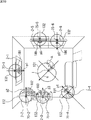
図2は、図1のリモートコントローラ1の構成例を示すブロック図である。
FIG. 2 is a block diagram illustrating a configuration example of the
リモートコントローラ1は、受光部21、情報検出部32、端末推定部33、通信回線最適制御部34、操作入力部35、モード設定部36、情報送信部37、および発光部38により構成される。
The
受光部21は、方位分離光学系11を有したイメージセンサ51(図3)で構成され、方位分離光学系11によって、送信されてくる情報に対応する光信号を方位毎に分離して受光(受信)する。
The
情報検出部32は、受光部21により受光された方位毎の光信号から、送信元の端末2のID情報を取得するとともに、その信号の光強度情報(以下、受信強度(RSSI)情報とも称する)を検出し、検出したID情報および受信強度情報を端末推定部33に供給する。
The
端末推定部33は、情報検出部32より得られる受光位置情報から推定方向(リモートコントローラ1からの相対方位)を算出し、受信強度情報から推定距離を算出することで、リモートコントローラ1から見た端末2の位置を推定し、推定した端末2の位置を、ID情報に関連付けて、通信回線最適制御部34に供給する。
The
通信回線最適制御部34は、接続優先度算出部41および制御情報算出部42により構成され、端末推定部33により推定された端末2の位置、モード設定部36からの操作モード情報、および操作入力部35からの操作情報に基づいて、各端末2の処理を制御する制御情報を算出する。
The communication line
接続優先度算出部41は、端末推定部33により推定された端末2の位置に基づく、ユーザAによるリモートコントローラ1の操作の正面方向(以下、操作方向とも称する)と位置(すなわち、各端末2との距離)により、各端末2の接続優先度を算出する。
The connection
制御情報算出部42は、操作入力部35から操作情報が供給されると、情報送信部37を制御し、発光部38から、呼びかけのための光信号である呼びかけ信号を送信させる。また、制御情報算出部42は、接続優先度算出部41により算出される各端末2の接続優先度、モード設定部36からの操作モード情報、および操作入力部35からの操作情報に基づいて、各端末2の処理を制御する制御情報を算出し、各端末2のID情報とともに情報送信部37に供給する。
When the operation information is supplied from the
なお、リモートコントローラ1は、操作モードとして、ユーザAが単一の端末2を選択して操作を行いたい場合に用いられる選択モードと、複数の端末2に対して接続優先度に応じた度合いの操作を行いたい場合に用いられる並列モードを有している。
The
例えば、操作モードが選択モードである場合、制御情報算出部42においては、ユーザAのリモートコントローラ1の操作方向で、かつ、より近い距離にある端末2の制御情報のみが算出される。操作モードが並列モードである場合、制御情報算出部42においては、ユーザのリモートコントローラ1の操作方向で、かつ、より近い距離にある端末2だけでなく、その端末2の周囲に存在する端末2の制御情報も、それぞれの接続優先度に応じて算出される。
For example, when the operation mode is the selection mode, the control
操作入力部35は、リモートコントローラ1の筐体の前面に備えられるボタンやダイヤルなどで構成され、ユーザAの操作に対応する操作情報を、制御情報算出部42およびモード設定部36に供給する。
The
モード設定部36は、操作入力部35を介して入力される操作モードに関するユーザAの操作情報に応じて、リモートコントローラ1の操作モードを、選択モードまたは並列モードに設定し、操作モード情報を制御情報算出部42に供給する。
The
情報送信部37は、制御情報算出部42からの各端末2のID情報および制御情報を、発光部38を介して送信させる。
The
発光部38は、無指向性光学系を有して構成され、受光部21の近傍に設置されている。発光部38は、情報送信部37からの各端末2のID情報および制御情報に対応する光信号を、端末2−1乃至2−3に向けて送信する。
The
なお、発光部38も方位分離光学系11を有する発光素子からなるセンサで構成することもできる。この場合、リモートコントローラ1は、各端末2のID情報および制御情報に対応する光信号を、そのID情報が対応する方位へ送信するため、図4を参照して後述する対応情報が、逆換算されて求められるセンサ配列[x,y]の発光素子からのみ発光させるように構成される。これにより、対応する端末2にだけ、そのID情報および制御情報に対応する光信号を送ることができるようになる。
The
また、このとき、プリズムなどを用いて、受光部21の方位分離光学系11を発光部38とで共用することもできる。さらに、イメージセンサ51のセンサ素子を受光素子および発光素子で構成することで、方位分離光学系11だけでなくイメージセンサ51も受光部21と発光部38で共用することができる。
At this time, the orientation separating
図3は、図2の受光部21の詳細な構成例を示している。
FIG. 3 shows a detailed configuration example of the
受光部21は、光学的レンズ機構からなる方位分離光学系11と、センサ配列[x,y](x:横,y:縦)の受光素子からなるイメージセンサ51で構成される。なお、イメージセンサ51は、PSD(Position Sensitive Detector)センサで構成することもできる。方位分離光学系11は、レンズ機構に限らず、例えば、光学スリット機構により構成することもできる。ただし、光受光感度を上げるため、レンズ機構を構成する方が好ましい。
The
方位分離光学系11は、光軸をイメージセンサ51の中心に合わせ、イメージセンサ51の距離Dだけ手前に配置されている。方位分離光学系11は、イメージセンサ51に到来する各端末2からの光信号を方位毎に分離し、イメージセンサ51の各受光素子に導く。
The azimuth separating
イメージセンサ51には、方位分離光学系11を介して、例えば、各端末2が存在する方向[φ,θ](地面に対して水平な平面における角度φ,地面に対して垂直な平面における角度θ)からの光信号が受光される。
For example, the direction [φ, θ] in which each
イメージセンサ51は、図4に示されるように、センサ配列[x,y](1≦x≦X,1≦y≦Y)の受光素子で構成されている。各受光素子と対応する到来方向(φxy,θxy)は、方位分離光学系11の配置とセンサ配列によって決定され、各受光素子のセンサ配列[x,y]と、対応する到来方向[φ,θ]は、例えば、端末位置推定部33に内蔵されるメモリ52に対応情報として記録されている。
As shown in FIG. 4, the
図4の例の場合、メモリ52には、イメージセンサ51のセンサ配列[1,1]の受光素子には、到来方向[φ11,θ11]が対応しており、イメージセンサ51のセンサ配列[1,2]の受光素子には、到来方向[φ12,θ12]が対応しており、イメージセンサ51のセンサ配列[m,n]の受光素子Pには、到来方向[φmn,θmn]が対応していることが記録されている。
In the example of FIG. 4, the arrival direction [φ11, θ11] corresponds to the light receiving elements of the sensor array [1, 1] of the
図3に戻って、情報検出部32は、各受光素子に対応するよう、受光素子数(すなわち、X×Y個)に内部的に分けられて構成されている。すなわち、センサ配列[1,1]の受光素子で受光された光信号に対応する情報は、情報検出部32−[1,1]に入力され、センサ配列[m,n]の受光素子で受光された光信号に対応する情報は、情報検出部32−[m,n]に入力され、センサ配列[x,y]の受光素子で受光された光信号に対応する情報は、情報検出部32−[x,y]に入力され、センサ配列[X,Y]の受光素子で受光された光信号に対応する情報は、情報検出部32−[X,Y]に入力される。
Returning to FIG. 3, the
情報検出部32−[1,1]は、センサ配列[1,1]の受光素子からの情報から、ID情報を取得するとともに、センサ配列[1,1]の受光素子で受光された光信号の受信強度情報を検出し、検出したID情報および受信強度情報を端末推定部33に供給する。情報検出部32−[m,n]は、センサ配列[m,n]の受光素子からの情報から、ID情報を取得するとともに、センサ配列[m,n]の受光素子で受光された光信号の受信強度情報を検出し、検出したID情報および受信強度情報を端末推定部33に供給する。
The information detection unit 32- [1,1] acquires ID information from information from the light receiving elements of the sensor array [1,1], and also receives an optical signal received by the light receiving elements of the sensor array [1,1]. Is received, and the detected ID information and received intensity information are supplied to the
情報検出部32−[X,Y]は、センサ配列[X,Y]の受光素子からの情報から、ID情報を取得するとともに、センサ配列[X,Y]の受光素子で受光された光信号の受信強度情報を検出し、検出したID情報および受信強度情報を端末推定部33に供給する。情報検出部32−[X,Y]は、センサ配列[X,Y]の受光素子からの情報から、ID情報を取得するとともに、センサ配列[X,Y]の受光素子で受光された光信号の受信強度情報を検出し、検出したID情報および受信強度情報を端末推定部33に供給する。
The information detection unit 32- [X, Y] acquires ID information from information from the light receiving elements of the sensor array [X, Y] and also receives an optical signal received by the light receiving elements of the sensor array [X, Y]. Is received, and the detected ID information and received intensity information are supplied to the
端末推定部33は、ID情報および受信強度情報を供給してくる情報検出部32に対応する受光素子の位置情報(例えば、情報検出部32−[m,n]に対応する受光素子Pの位置情報であるセンサ配列[m,n])から、推定方位を算出し、受信強度情報から推定距離を算出することで、リモートコントローラ1から見た端末2の位置を推定し、この位置推定情報をID情報に関連付けて、通信回線最適制御部34に供給する。
The
なお、図3の例の受光部21においては、説明の便宜上、背面からの光信号が受信できないように示されているが、受光部21を、全方位からの光信号を受信可能に、例えば、複数のミラー、レンズおよびセンサで構成することもできる。
In the
図5は、図1の端末2の構成例を示すブロック図である。
FIG. 5 is a block diagram illustrating a configuration example of the
端末2は、受光部71、発光部72、機能制御部73、機能処理部74、インジケータ75、および電源供給部76により構成される。
The
受光部71は、無指向性光学系を有して構成され、送信されてくる光信号を受光し、受光した光信号に対応する情報を機能制御部73に供給する。発光部72も無指向性光学系を有して構成され、受光部71の近傍に設置されている。発光部72は、送信する情報に対応する光信号を発光する。
The
これらの受光部71および発光部72においても、プリズムなどを用いることで、無指向性光学系を共有することが可能である。
The
機能制御部73は、受光部71を介して、リモートコントローラ1からの呼びかけ信号を受信すると、内蔵する図示せぬメモリから、端末2のID情報を読み出し、そのID情報を、発光部72に送信させる。また、機能制御部73は、受光部71を介して、リモートコントローラ1からの制御情報を受信すると、まず、制御情報に付加されているID情報を検出し、メモリのID情報と一致するか否かを判定し、メモリのID情報と一致した場合に、その制御情報に基づいて、機能処理部74、インジケータ75、および電源供給部76の処理を制御する。
When the
機能処理部74は、図5の例の場合、チューナ81、信号処理部82、モニタ83、スピーカ84により構成される。なお、図5の例においては、端末2がテレビジョン受信装置で構成される場合の機能処理部74が示されており、例えば、端末2がテレビジョン受信装置以外のCE機器である場合、機能処理部74は、その装置に応じた構成となる。
In the example of FIG. 5, the
チューナ81は、図示せぬアンテナにより受信された放送信号から、機能制御部73の制御に応じた選局を行い、所定の処理が施された信号を、画像信号と音声信号に分離して、信号処理部82に出力する。
The
信号処理部82は、チューナ81からの画像信号に、機能制御部73の制御に応じた画像処理を行い、チューナ81からの音声信号に、機能制御部73の制御に応じた音声処理を行う。また、信号処理部82は、処理後の画像信号に対応する画像をモニタ83に表示させ、処理後の音声信号に対応する音声をスピーカ84から出力させる。
The
モニタ83は、LCD(Liquid Crystal Display)などで構成され、信号処理部82からの画像信号に対応する画像を表示する。また、モニタ83は、機能制御部73の制御に応じて、モニタ83自体の明るさや解像度などを調整する。スピーカ84は、信号処理部82からの音声信号に対応する音声を出力する。また、スピーカ84は、機能制御部73の制御に応じて、音量や音質などを調整する。
The
インジケータ75は、LED(Light Emitting Diode)などで構成され、機能制御部73の制御に応じて、点灯する。電源供給部76は、機能制御部73の制御に応じて、端末2の各部への電源の供給を開始したり、停止する。
The
次に、接続優先度算出部41による接続優先度の算出について説明する。
Next, calculation of connection priority by the connection
各端末2の接続優先度の算出は、ユーザAのリモートコントローラ1の操作方向および位置(各端末2との距離)により算出される。例えば、端末2をaとし、リモートコントローラ1をxとすると、リモートコントローラ1から、各端末2への接続優先度Yx->aの算出は、次の式(1)で表される。
The connection priority of each terminal 2 is calculated based on the operation direction and position of the

まず、接続優先度Yx->aを算出する際には、方位分離光学系11を有するリモートコントローラ1については、任意方位(θxa,φxa)からの信号に対しての指向性パターンFx(θxa,φxa)として、例えば、図6の指向性パターン131が設定される。
First, when calculating the connection priority Yx-> a, the
指向性パターンについて、図6を参照して説明する。指向性パターンとは、x,y,zの3次元の空間におけるすべての方位、すなわち、xy平面上における角度θ(deg)およびyz平面における角度φ(deg)への通信に対する要望の大きさである指向性指数を表すものである。 The directivity pattern will be described with reference to FIG. The directivity pattern is the magnitude of demand for communication to all orientations in a three-dimensional space of x, y, and z, that is, an angle θ (deg) on the xy plane and an angle φ (deg) on the yz plane. It represents a certain directivity index.
図6は、説明の便宜上、3次元のうち、z次元が省略された、すなわち、3次元のうち、x,yの2次元(xy平面)における、各方位に対する指向性指数f(θ,φ)を表すグラフ121と、縦軸を指向性指数F(θ,φ)とし、横軸を方位θ(グラフ121の同じ方位を示す)としたグラフ122を示しており、グラフ121およびグラフ122には、それぞれ正面指向性型の指向性パターン131と、無指向性型の指向性パターン132が示されている。
FIG. 6 illustrates the directivity index f (θ, φ for each direction in the three dimensions, in which the z dimension is omitted, that is, in the two dimensions x and y (xy plane) of the three dimensions. ), And a
グラフ121において、原点は、リモートコントローラ1あるいは端末2の位置を示し、xy平面の各円は、−50(原点)から、−10刻みの指向性指数を表している。また、グラフ121においては、y軸上において上方向が0度を表し、360度の方位が0度から時計回りに設定されており、0度の方位が、リモートコントローラ1の操作(あるいは端末2)の正面方向qとされている。
In the
正面指向性型の指向性パターン131は、正面方向qの方位に対しては、略3と大きく、正面方向qの方位から、原点を中心に背面方向に回転するにつれて、だんだん小さくなり、背面方向(180度)の方位に対しては、略−40と急に小さくなっていく指向性指数を有している。したがって、正面指向性型の指向性パターン131の指向性指数は、グラフ121においては、凹んだ形状で表され、グラフ122においては、凸型の2次曲線で表される。
The
無指向性型の指向性パターン132は、どの方位に対しても一定で同じ大きさ(略0)である(すなわち、無指向である)指向性指数を有している。したがって、無指向性型の指向性パターン132の指向性指数は、グラフ121においては、正円の形状で表され、グラフ122においては、x軸に平行な直線で表される。
The
したがって、リモートコントローラ1について、任意方位(θxa,φxa)からの信号に対しての指向性パターンFx(θxa,φxa)として、図6の指向性パターン131を設定することにより、式(1)で表される接続優先度Yx->aは、リモートコントローラ1の操作方向を中心に次第に減衰していくようになる。
Therefore, by setting the
また、式(1)において、*は、乗算を表しており、Y0は、接続優先度の正規化係数、Ptaは、端末2の送信電力利得、Ga(x)は、端末2のリモートコントローラ1に対する利得、Fa(θax,φax)は、端末2のリモートコントローラ1方向に対する指向性利得を表している。なお、図1の通信制御システムにおいては、端末2の送信電力利得Pta、および端末2のリモートコントローラ1に対する利得Ga(x)は、一定値とし、端末2のリモートコントローラ1方向に対する指向性利得Fa(θax,φax)は、無指向性光学系を有することから、例えば、図6の指向性パターン132で示される無指向性とする。
In Equation (1), * represents multiplication, Y0 is a connection priority normalization coefficient, Pta is the transmission power gain of the
さらに、式(1)において、Gx(a)は、リモートコントローラ1の端末2に対する利得、Prxは、リモートコントローラ1の端末2に対する受信電力利得であり、これらについても各端末2に対して一定とされる。また、式(1)の分母であるLa<->xは、端末2とリモートコントローラ1間の距離によって変化する減衰量であり、通信に用いる光の波長や電波の周波数などにより変動する値である。
Further, in equation (1), Gx (a) is the gain of the
以上により、リモートコントローラ1の各端末2に対する接続優先度Yx->aは、リモートコントローラ1の任意方位に対する指向性パターンFx(θxa,φxa)と、リモートコントローラ1から各端末2方位に対する距離によって変化する減衰量La<->xの比率によって算出されることがわかる。
As described above, the connection priority Yx-> a for each
次に、図7および図8を参照して、リモートコントローラ1の操作方向における接続優先度Yx->aの変化について説明する。
Next, a change in connection priority Yx-> a in the operation direction of the
図7は、リモートコントローラ1を操作するユーザ、すなわち、リモートコントローラ1を基準とした空間座標を表している。すなわち、リモートコントローラ1は、座標[0,0]([x座標,y座標]を示す)に位置している。
FIG. 7 shows spatial coordinates based on the user who operates the
したがって、このリモートコントローラ1を基準とした空間座標においては、y軸の上方向(図中上方向)が、リモートコントローラ1の操作の正面方向qに対しての相対方位が0度を示しており、リモートコントローラ1を軸として、0度から時計回りに90度回転した位置が+90度の相対方位、0度から時計回りに180度回転した位置が±180度の相対方位、かつ、0度から反時計回りに90度回転した位置が−90度の相対方位をそれぞれ示している。換言すると、相対方位が+90度の位置は、操作の右方向であり、相対方位が±180度の位置は、操作の背面方向であり、相対方位が−90度の位置は、操作の左方向を示している。
Therefore, in the spatial coordinates based on the
また、図7に示される空間座標に示される原点(ユーザA)を中心とする3つの円(点線)の半径は、内側からそれぞれ、リモートコントローラ1からの距離が10m、20m、30mであることを表している。
Further, the radii of the three circles (dotted lines) centered on the origin (user A) shown in the spatial coordinates shown in FIG. 7 are 10 m, 20 m, and 30 m from the
図7の例の場合、リモートコントローラ1の指向性は、図6を参照して上述したように、正面指向性型の指向性パターン131であり、リモートコントローラ1を基準とした空間座標には、各端末2−1乃至2−3が存在する位置が示されている。
In the case of the example of FIG. 7, the directivity of the
端末2−1は、リモートコントローラ1との相対距離が略25mで、リモートコントローラ1との相対方位が略0度の位置に存在している。端末2−2は、リモートコントローラ1との相対距離が略23mで、リモートコントローラ1との相対方位が略+120度の位置に存在している。端末2−3は、リモートコントローラ1との相対距離が略20mで、リモートコントローラ1との相対方位が略−90度の位置に存在している。
The terminal 2-1 has a relative distance to the
以上のような空間座標において、ユーザAは、リモートコントローラ1の操作の正面方向qを変更させると、リモートコントローラ1の各端末2に対する接続優先度は、図8に示されるように変化する。
In the spatial coordinates as described above, when the user A changes the front direction q of the operation of the
図8においては、縦軸が接続優先度を表し、横軸は、図7の空間座標におけるリモートコントローラ1の操作の正面方向qの向き(θ)を表している。
In FIG. 8, the vertical axis represents the connection priority, and the horizontal axis represents the direction (θ) of the front direction q of the operation of the
端末2−1は、図7の空間座標において、リモートコントローラ1との相対距離が25mで、リモートコントローラ1の操作の正面方向qとの相対方位が略0度の方位に位置している。したがって、図8に示されるリモートコントローラ1の端末2−1に対する接続優先度151−1は、リモートコントローラ1の操作の正面方向qが0度の方位を向いたときに一番高くなり、リモートコントローラ1の操作の正面方向qが、0度の方位からリモートコントローラ1を中心に、時計回りまたは反時計回りに回転していく毎に、だんだん下がっていく。
The terminal 2-1 has a relative distance of 25 m with respect to the
同様に、端末2−2は、図7の空間座標において、リモートコントローラ1との相対距離が23mで、リモートコントローラ1の操作の正面方向qとの相対方位が略+120度の方位に位置している。したがって、図8に示されるリモートコントローラ1の端末2−2に対する接続優先度151−2は、リモートコントローラ1の操作の正面方向qが+120度の方位を向いたときに一番高くなり、リモートコントローラ1の操作の正面方向qが、+120度の方位からリモートコントローラ1を中心に、時計回りまたは反時計回りに回転していく毎に、だんだん下がっていく。
Similarly, the terminal 2-2 has a relative distance of 23 m from the
さらに、端末2−3は、図7の空間座標において、リモートコントローラ1との相対距離が20mで、リモートコントローラ1の操作の正面方向qとの相対方位が略−90度の方位に位置している。したがって、図8に示されるリモートコントローラ1の端末2−3に対する接続優先度151−3は、リモートコントローラ1の操作の正面方向qが−90度の方位を向いたときに一番高くなり、リモートコントローラ1の操作の正面方向qが、−90度の方位からリモートコントローラ1を中心に、時計回りまたは反時計回りに回転していく毎に、だんだん下がっていく。
Furthermore, the terminal 2-3 has a relative distance of 20 m in the spatial coordinates of FIG. 7 and a relative azimuth with the front direction q of the operation of the
したがって、図7の空間座標におけるリモートコントローラ1の各端末2に対する接続優先度を比較した場合、リモートコントローラ1の操作の正面方向qが0度の方位(すなわち、端末2−1の方向)を向いたとき、点線L1上の丸に示されるように、接続優先度151−1(白丸)>接続優先度151−3(ハッチング丸)>接続優先度151−2(黒丸)となる。
Accordingly, when the connection priorities of the
また、リモートコントローラ1の操作の正面方向qが+120度の方位(すなわち、端末2−2の方向)を向いたとき、点線L2上の丸に示されるように、接続優先度151−2(黒丸)>>接続優先度151−3(ハッチング丸)>接続優先度151−1(白丸)となる。
Further, when the front direction q of the operation of the
さらに、リモートコントローラ1の操作の正面方向qが−90度の方位(すなわち、端末2−3の方向)を向いたとき、点線L3上の丸に示されるように、接続優先度151−3(ハッチング丸)>接続優先度151−1(白丸)>接続優先度151−2(黒丸)となる。
Further, when the front direction q of the operation of the
以上のように、図6の指向性パターン131を有するリモートコントローラ1の各端末2に対する接続優先度Yx->aは、リモートコントローラ1から各端末2に対する距離によっても変化するが、それ以上に、リモートコントローラ1の操作の正面方向qに応じて変化し、リモートコントローラ1の操作の正面方向qに位置する端末2の接続優先度が他の端末2の接続優先度よりも大きくなることがわかる。
As described above, the connection priority Yx-> a for each
次に、リモートコントローラ1の操作モードについて説明する。リモートコントローラ1は、図2を参照して上述したように、操作モードとして、選択モードおよび並列モードを有している。
Next, the operation mode of the
まず、図9を参照して、選択モードについて説明する。選択モードは、ユーザが単一の端末2を選択して操作を行いたい場合に用いられる操作モードであり、リモートコントローラ1の操作のほぼ正面方向であり、かつ、リモートコントローラ1からより近い距離にある接続優先度が最も高い端末2を1つ選択して操作を行うモードである。
First, the selection mode will be described with reference to FIG. The selection mode is an operation mode that is used when the user wants to select and operate a
図9に示される室内空間の所定の位置には、リモートコントローラ1により操作される被操作端末としての端末2−1乃至2−6が設置されている。端末2−1乃至2−6は、図9の例においては、テレビジョン受像機、オーディオ機器、エアーコンディショナ装置、自動シャッタ装置、照明装置、およびビデオ録画装置などからなり、機能処理部74の詳細な構成が異なる以外は、図5の端末2と基本的に同様に構成されている。
Terminals 2-1 to 2-6 as operated terminals operated by the
端末2の指向性は、基本的に、図6を参照して上述したように、指向性パターン132が示す無指向性であり、各端末2−1乃至2−6の上部中央には、光を点灯する発光素子からなるインジケータ75−1乃至75−6が設置されている。
The directivity of the
具体的には、端末2−1は、テレビジョン受像機により構成され、正面方向p1を図中下に向けて、室内空間の図中上側の壁に設置されている。端末2−2は、ビデオ録画装置により構成され、正面方向p2を図中右に向けて、室内空間の図中左上隅に設置されている。端末2−3は、オーディオ機器により構成され、正面方向p3を図中右上に向けて、室内空間の図中左の端末2−2の隣に設置されている。 Specifically, the terminal 2-1 is configured by a television receiver, and is installed on the upper wall in the drawing of the indoor space with the front direction p1 facing downward in the drawing. The terminal 2-2 is composed of a video recording device, and is installed in the upper left corner of the room space with the front direction p2 facing the right side in the figure. The terminal 2-3 is configured by an audio device, and is installed next to the terminal 2-2 on the left side in the room space with the front direction p3 facing the upper right side in the figure.
端末2−4は、照明装置により構成され、正面方向p4を図中右上に向けて、室内空間の図中左下隅に設置されている。端末2−5は、エアーコンディショナ装置により構成され、正面方向p5を図中左に向けて、室内空間の図中右側の壁に設置されている。端末2−6は、自動シャッタ装置により構成され、正面方向p6を図中左に向けて、室内空間の図中右側の壁の端末2−5の近傍(図中下方)に設置されている。 The terminal 2-4 is configured by a lighting device, and is installed in the lower left corner of the room space with the front direction p4 facing the upper right in the figure. The terminal 2-5 is configured by an air conditioner device, and is installed on the right wall of the indoor space in the drawing with the front direction p5 facing the left in the drawing. The terminal 2-6 is composed of an automatic shutter device, and is installed in the vicinity (lower part in the figure) of the terminal 2-5 on the right wall in the figure of the indoor space with the front direction p6 directed to the left in the figure.
このような室内空間の略中央において、ユーザAは、方位分離光学系11を有し、図6を参照して上述した正面指向型(すなわち、操作の正面方向qに最大の利得を持つ)の指向性パターン131を有するリモートコントローラ1を用いて、リモートコントローラ1の正面方向qを室内空間の図中左上隅に向けて、例えば、端末2の電源をオフする操作を行う。
At substantially the center of such indoor space, the user A has the azimuth separating
このとき、リモートコントローラ1は、呼びかけ信号を送信するので、呼びかけ信号を受信した各端末2は、ID情報に対応する光信号をそれぞれ送信してくる。リモートコントローラ1は、受信した光信号から、各端末2のID情報、受信強度情報、および受光位置情報を得て、受光位置情報から推定方向を算出し、受信強度情報から推定距離を算出することで、端末2の位置を推定し、それに基づいて、各端末2に対する接続優先度を算出し、算出された接続優先度情報、操作モード情報、および操作入力部35からの操作情報に基づいて、各端末2の処理を制御する制御情報を算出する。
At this time, since the
いまの場合、リモートコントローラ1の正面方向qに位置する端末2−2の接続優先度が最も高く、操作モードが選択モードであり、電源をオフする操作情報が入力されているので、リモートコントローラ1においては、端末2−2のインジケータ75−2を点灯させ、端末2−2の電源をオフさせる制御情報が算出され、端末2−2のID情報とともに、光信号として送信される。
In this case, since the connection priority of the terminal 2-2 located in the front direction q of the
各端末2は、リモートコントローラ1からの光信号を受信するが、ID情報が一致する端末2−2のみ、リモートコントローラ1からの制御情報に基づいて、インジケータ75−2の点灯171を行い、その後、電源をオフする。
Each
なお、リモートコントローラ1に対して、選択モードを設定する操作を行うことで、インジケータ75の点灯171を確認してから、電源をオフする操作を新たに行うようにすることも可能である。
It is also possible to newly perform an operation of turning off the power after confirming the
以上のように、リモートコントローラ1の操作モードを選択モードに設定することで、ユーザAは、リモートコントローラ1を向け、インジケータ75−2の点灯171により端末2−2が選択されていることをユーザAに提示している端末2−2だけの操作を行うことができる。
As described above, by setting the operation mode of the
次に、図10を参照して、並列モードについて説明する。なお、図10において、図9と対応する部分には対応する符号が付してあり、その説明は繰り返しになるので、適宜省略する。また、図10の例においては、説明の便宜上、すべての端末2が、音声を出力するスピーカ84を有しているものとして説明する。
Next, the parallel mode will be described with reference to FIG. 10, parts corresponding to those in FIG. 9 are denoted by corresponding reference numerals, and the description thereof will be repeated, and will be omitted as appropriate. In the example of FIG. 10, for convenience of explanation, it is assumed that all
並列モードは、複数の端末2に対して接続優先度に応じた度合いの操作を行いたい場合に用いられる操作モードであり、リモートコントローラ1の操作のほぼ正面方向であり、かつ、より近い距離にある端末2だけでなく、その端末2の周囲に存在する端末2に対しても、それぞれの接続優先度情報に応じて並列に操作を行うモードである。
The parallel mode is an operation mode used when it is desired to perform an operation of a degree corresponding to the connection priority with respect to a plurality of
図9と同様に端末2が配置される図10の室内空間の略中央において、ユーザAは、方位分離光学系11を有し図6を参照して上述した正面指向型(すなわち、操作の正面方向qに最大の利得を持つ)の指向性パターン131を有するリモートコントローラ1を用いて、リモートコントローラ1の正面方向qを室内空間の図中左上隅に向けて、例えば、音量のボリュームを10上げる操作を行う。
As in FIG. 9, in the approximate center of the indoor space of FIG. 10 in which the
このとき、リモートコントローラ1は、図9の場合と同様に、呼びかけ信号を送信するので、呼びかけ信号を受信した各端末2は、ID情報に対応する光信号をそれぞれ送信してくる。リモートコントローラ1は、受信した光信号から、ID情報、受信強度情報、および受光位置情報を得て、受光位置情報から推定方向を算出し、受信強度情報から推定距離を算出することで、端末2の位置を推定し、それに基づいて、各端末2に対する接続優先度を算出し、算出された接続優先度情報、操作モード情報、操作入力部35からの操作情報に基づいて、各端末2の処理を制御する制御情報を算出する。
At this time, since the
いまの場合、リモートコントローラ1の正面方向qに位置する端末2−2の接続優先度が最も高く、正面方向q(例えば、0度の方位)から相対角度が浅い(すなわち、±90度以内の)位置に配置される端末2−1および2−3の接続優先度が、端末2−2の接続優先度に次いで高く、その後、正面方向qから相対角度が±135度以内の位置に配置される端末2−4および2−5の接続優先度が、端末2−1および2−3の接続優先度に次いで高く、正面方向qの略背面方向に位置する端末2−6の接続優先度が一番低くなっている。
In this case, the connection priority of the terminal 2-2 located in the front direction q of the
さらに、操作モードが並列モードであり、音量を10上げる操作情報が入力されているので、リモートコントローラ1においては、各端末2の接続優先度の度合いに応じて、各端末2のインジケータ75を点灯させ、かつ、各端末2の音量を上げる制御情報が算出され、各端末2のID情報とともに、光信号として送信される。
Further, since the operation mode is the parallel mode and operation information for increasing the volume by 10 is input, the
例えば、接続優先度が最も高い端末2−2のID情報とともに、最も高い接続優先度に応じて算出された最大強度での点灯や操作範囲内における最大の音量アップを制御する制御情報が送信される。また、他の端末2−1および端末2−3乃至2−6についても、それらのID情報とともに、各接続優先度の度合いに応じた強度での点灯や各接続優先度の度合いに応じた音量アップを制御する制御情報が送信される。 For example, together with the ID information of the terminal 2-2 having the highest connection priority, control information for controlling lighting at the maximum intensity calculated according to the highest connection priority and maximum volume increase within the operation range is transmitted. The Further, for the other terminals 2-1 and 2-2 to 2-6, together with their ID information, lighting at an intensity corresponding to the degree of each connection priority and a volume corresponding to the degree of each connection priority Control information for controlling up is transmitted.
リモートコントローラ1からは、各端末2への制御情報がID情報とともに光信号として送信されてくるので、各端末2は、リモートコントローラ1からの光信号を受信し、ID情報が一致する制御情報に基づいて、インジケータ75の点灯を行い、音量を上げる処理を行う。
Since the
すなわち、接続優先度が最も高い端末2−2は、リモートコントローラ1からの制御情報に基づいて、最大数の発光素子が(最大強度で)点灯するように点灯182を行い、音量を10上げる処理を行う。
That is, the terminal 2-2 having the highest connection priority performs the
接続優先度が端末2−2の次に高い端末2−1および2−3は、リモートコントローラ1からの制御情報に基づいて、最大強度の点灯182よりも少し弱く点灯するように点灯181および183を行い、音量を、例えば、7上げる処理を行う。
The terminals 2-1 and 2-3 having the second highest connection priority after the terminal 2-2 are lit 181 and 183 so as to light slightly weaker than the
接続優先度が端末2−1および2−3の次に高い端末2−4および2−5は、リモートコントローラ1からの制御情報に基づいて、点灯181および183よりも少し弱く点灯するように点灯184および185を行い、音量を、例えば、5上げる処理を行う。
The terminals 2-4 and 2-5 having the second highest connection priority after the terminals 2-1 and 2-3 are lit so as to light slightly weaker than the
接続優先度が一番低い端末2−6は、リモートコントローラ1からの制御情報に基づいて、他の提示情報に比較して最弱の強度に点灯するように点灯186を行い、音量を、例えば、3上げる処理を行う。
Based on the control information from the
以上のように、リモートコントローラ1の操作モードを並列モードに設定することで、ユーザAは、室内空間においてインジケータ75の点灯を見ることにより、端末2がどのくらいのバランスで操作可能であるかを確認することができ、例えば、リモートコントローラ1の操作方向や位置を動かして、所望のバランスで複数の端末2の操作を行うことができる。
As described above, by setting the operation mode of the
なお、図9を参照して上述した選択モードの場合にも、最も接続優先度の高い端末2の位置がわかるので、例えば、操作の内容が、電源のオンオフではなく、音量アップのように数値を指示可能な操作の場合には、その位置に応じた度合いの制御を行うこともできる。
In the case of the selection mode described above with reference to FIG. 9, the position of the
次に、図11のフローチャートを参照して、図1の通信制御システムの処理について説明する。なお、図11の例の場合、リモートコントローラ1においては、操作モードとして並列モードが設定されているとする。
Next, processing of the communication control system of FIG. 1 will be described with reference to the flowchart of FIG. In the case of the example of FIG. 11, it is assumed that the parallel mode is set as the operation mode in the
例えば、ユーザAは、リモートコントローラ1の方位分離光学系11を端末2−2に向けて、リモートコントローラ1に対して、端末2のスピーカ84の音量を10上げる操作を行う。
For example, the user A directs the azimuth separating
ステップS11において、リモートコントローラ1の操作入力部35は、ユーザAの操作を入力し、ユーザAの操作に対応する操作情報を制御情報算出部42に供給する。操作情報が供給されると、ステップS12において、制御情報算出部42は、情報送信部37を制御し、発光部38から呼びかけ信号を送信させる。
In step S <b> 11, the
端末2の受光部71は、ステップS21において、リモートコントローラ1からの呼びかけ信号を受信し、機能制御部73に供給する。呼びかけ信号が供給されると、ステップS22において、機能制御部73は、内蔵する図示せぬメモリから、端末2のID情報を読み出し、そのID情報を発光部72に送信させる。
In step S <b> 21, the
端末2から、ID情報に対応する光信号が送信されてくるので、リモートコントローラ1の受光部21は、ステップS13において、端末2からの光信号を受信する。すなわち、端末2からの光信号は、方位分離光学系11により方位毎に分離され、例えば、イメージセンサ51のセンサ配列[m,n]の受光素子Pに導かれる。
Since the optical signal corresponding to the ID information is transmitted from the
ステップS14において、情報検出部32および端末推定部33は、受信された光信号を用いて、受信強度情報、および端末2のID情報を検出し、推定方位を算出し、リモートコントローラ1からの距離である、端末2の位置を推定する。
In step S14, the
すなわち、ステップS14において、受光素子Pに対応する情報検出部32−[m,n]は、受光素子Pに受光された光信号の受信強度情報を取得し、光信号に対応する情報から、ID情報を取得し、検出したID情報および受信強度情報を端末推定部33に供給する。端末推定部33は、ID情報および受信強度情報を供給してくる情報検出部32−[m,n]に対応する受光素子Pの位置情報から、推定方位を算出し、受信強度情報から推定距離を算出することで、端末2の位置を推定し、この端末位置推定情報をID情報に関連付けて、通信回線最適制御部34に供給する。
That is, in step S14, the information detection unit 32- [m, n] corresponding to the light receiving element P acquires the reception intensity information of the optical signal received by the light receiving element P, and from the information corresponding to the optical signal, ID Information is acquired, and the detected ID information and received intensity information are supplied to the
以上のステップS13およびS14の処理は、複数の光信号が同時に到来した場合には同時に並行して行われる。 The processes in steps S13 and S14 described above are performed in parallel when a plurality of optical signals arrive at the same time.
ステップS15において、接続優先度算出部41は、端末推定部33により推定された端末2の位置に基づく、ユーザによるリモートコントローラ1の操作の正面方位と位置(すなわち、各端末2との距離)により、各端末2の接続優先度を算出する。
In step S <b> 15, the connection
ステップS16において、制御情報算出部42は、接続優先度算出部41により算出される各端末2の接続優先度、モード設定部36からの操作モード情報、および操作入力部35からの操作情報に基づいて、各端末2の処理を制御する制御情報を算出し、各端末2のID情報とともに情報送信部37に供給する。
In step S16, the control
図1の例の場合、リモートコントローラ1の操作の正面方向にいる端末2−2に対しては、最も高い接続優先度が算出されるので、制御情報算出部42は、例えば、スピーカ84の音量を10上げる制御情報を算出する。リモートコントローラ1の操作の正面方向より少し外れた位置にいる端末2−1または端末2−3に対しては、端末2−2よりも低い接続優先度が算出されるので、制御情報算出部42は、例えば、スピーカ84の音量を7上げる制御情報を算出する。
In the case of the example of FIG. 1, the highest connection priority is calculated for the terminal 2-2 in the front direction of the operation of the
ステップS17において、情報送信部37は、各端末2のID情報と制御情報を、発光部32に光信号として送信させる。
In step S17, the
端末2の受光部71は、ステップS23において、リモートコントローラ1からの光信号を受信し、光信号に対応する情報(制御情報およびID情報)を、機能制御部73に供給する。
In step S23, the
ステップS24において、機能制御部73は、ID情報が一致する制御情報に基づいて、制御情報により制御の対象となる、機能処理部74、インジケータ75、または電源供給部76などの制御を行う。
In step S <b> 24, the
例えば、端末2−2の機能制御部73は、制御情報に基づいて、スピーカ84の音量を10上げさせる制御を行う。一方、端末2−1および端末2−3の機能制御部73は、制御情報に基づいて、スピーカ84の音量を7上げさせる制御を行う。これにより、端末2−2のスピーカ84からは、10上がった音量で音声が出力され、端末2−1および端末2−3のスピーカ84からは、7上がった音量で音声が出力される。
For example, the
以上のように、図1の通信制御システムにおいては、リモートコントローラ1の受光部21を、光信号を方位毎に分離する方位分離光学系11を有して構成するようにしたので、複数の端末から信号が送信されてきたとしても、端末毎の信号を方位毎に分けて並行して受信することができる。
As described above, in the communication control system of FIG. 1, the
すなわち、機器間での同期処理や複雑な通信プロセス処理を行うことなく、並行通信が可能となる。 That is, parallel communication is possible without performing synchronization processing between devices or complicated communication process processing.
さらに、端末毎の信号を方位毎に分けて並行して受信することにより、端末2の方向、位置を推定することができるので、1の端末あるいは複数の端末に対して、その位置に応じた制御を行うことができる。これにより、ユーザは、リモートコントローラ1の操作方向を最も操作したい端末に向けて、操作を行うだけで、複数の端末を一度に操作することができる。
Furthermore, since the direction and the position of the
図12は、本発明の第2の実施の形態である通信制御システムを示している。 FIG. 12 shows a communication control system according to the second embodiment of the present invention.
図12の通信制御システムにおいては、方位分離光学系11を有するリモートコントローラ1が、無指向性光学系を有するリモートコントローラ201に入れ替わっている点、無指向性光学系を有する端末2−1乃至端末2−3が、方位分離光学系11を有する端末202−1乃至端末202−3に入れ替わっている点、並びに、端末202−1乃至202−3に情報を共有させるサーバ203が追加されている点が、図1の通信制御システムと異なっている。
In the communication control system of FIG. 12, the
すなわち、図12の通信制御システムにおいては、図1のリモートコントローラ1が行っていた、方位分離光学系11を用いて、通信相手の位置を推定する処理は、端末202−1乃至202−3によりそれぞれ実行され、推定された位置情報に基づいて接続優先度を求め、接続優先度情報に応じて、ユーザAの操作情報に対応する制御情報を算出する処理は、サーバ203により実行される。なお、以下、端末202−1乃至202−3を個々に区別する必要がない場合、単に端末202とも称する。
That is, in the communication control system of FIG. 12, the process of estimating the position of the communication partner using the azimuth separating
まず、ユーザAは、複数の端末202−1乃至202−3のうち、操作したい端末202の方向に向けて、リモートコントローラ201を操作する。
First, the user A operates the
リモートコントローラ201は、無指向性光学系を有して構成される発光部38を備えており、ユーザAの操作に対応する操作情報、操作モード情報、およびリモートコントローラ201のID情報を光信号として端末202の方向に対して送信する。
The
なお、リモートコントローラ201からは、少なくともリモートコントローラ201のID情報が送信されればよく、ユーザAの操作に対応する操作情報、操作モード情報は、例えば、無線通信205により、直接サーバ203に送信することもできる。
The
端末202−1乃至202−3は、図1の端末2−1乃至2−3と同様に、例えば、ユーザA宅に設置されるテレビジョン受信装置などで構成される。また、端末202−1乃至202−3は、送受信される情報に対応する光信号を方位毎に分離する方位分離光学系11−1乃至11−3を有し、図1の受光部21−1乃至21−3と同様に構成される受光部211−1乃至211−3をそれぞれ備えている。 The terminals 202-1 to 202-3 are configured by, for example, a television receiver installed in the user A's house, as with the terminals 2-1 to 2-3 of FIG. Also, the terminals 202-1 to 202-3 have azimuth separating optical systems 11-1 to 11-3 that separate optical signals corresponding to information to be transmitted and received for each azimuth, and the light receiving unit 21-1 in FIG. Light receiving units 211-1 to 211-3 configured similarly to 21 to 21-3, respectively.
端末202は、方位分離光学系11によって、リモートコントローラ1から送信されてくる光信号から、操作情報、操作モード情報、リモートコントローラ201のID情報、到来方向情報、光強度情報を検出して、端末202から見たリモートコントローラ201の位置を推定し、その位置推定情報を、ネットワーク204を介してサーバ203に送信する。
The terminal 202 detects operation information, operation mode information, ID information of the
また、端末202は、サーバ203からネットワーク204を介して送信されてくる制御情報に基づいて、電源のオンオフ、選局、音量調整、画質調整などの所定の処理を実行する。
Also, the terminal 202 executes predetermined processing such as power on / off, channel selection, volume adjustment, image quality adjustment, and the like based on control information transmitted from the
サーバ203は、リモートコントローラ201と無線通信205により情報を送受信可能に構成されており、ネットワーク204を介して、端末202−1乃至202−3に接続されている。なお、ネットワーク204は、有線または無線で構成することができる。
The
サーバ203は、各端末202からネットワーク204を介してそれぞれ送信されてくる、各端末202から見たリモートコントローラ201の位置推定情報、操作情報、および操作モード情報に基づいて、各端末202の制御情報を算出し、算出した制御情報を、ネットワーク204を介して、各端末202に対して送信する。
The
なお、図12の通信制御システムにおいては、端末202間の情報共有のためと、端末202の処理の負荷を軽減するために、ネットワーク204で接続されるサーバ203を構成し、サーバ203に制御情報を算出させるようにしたが、端末202間にアドホック通信回線からなるネットワーク204を確立させて、それぞれ情報共有をさせることで、所定の端末202あるいは各端末202において制御情報を算出するように構成することもできる。
In the communication control system of FIG. 12, in order to share information between the
また、図12の通信制御システムにおいては、1台のリモートコントローラ201と、3台の端末202−1乃至202−3、1台のサーバ203で構成されているが、端末202の数は3台に限定されない。さらに、リモートコントローラ201も、図18を参照して後述するように、複数台で構成することもできる。
12 includes one
図13は、図12のリモートコントローラ201の構成例を示すブロック図である。なお、図13のリモートコントローラ201においては、操作入力部35乃至発光部38を備える点は、図2のリモートコントローラ1と共通しているが、受光部21および情報検出部32乃至通信回路最適制御部34が除かれている点、並びに、通信制御部221および無線送信部222が追加されている点が異なっている。
FIG. 13 is a block diagram illustrating a configuration example of the
すなわち、図13の操作入力部35は、ユーザAの操作に対応する操作情報を、通信制御部221およびモード設定部36に供給する。モード設定部36は、選択モードまたは並列モードに設定している操作モード情報を通信制御部221に供給する。
That is, the
通信制御部221は、操作入力部35から、ユーザAの操作情報が供給されると、内蔵するメモリから、リモートコントローラ201のID情報を読み出し、情報送信部37を制御し、ID情報、ユーザAの操作情報、およびモード設定部36からの操作モード情報を、光信号として発光部38を介して送信させる。
When the operation information of the user A is supplied from the
なお、通信制御部221は、必要に応じて、無線送信部222を制御し、リモートコントローラ201のID情報に関連付けて、ユーザAの操作情報および操作モード情報をサーバ203に送信させる。
The
無線送信部222は、通信制御部221の制御のもと、無線通信により、リモートコントローラ201のID情報、ユーザAの操作情報および操作モード情報をサーバ203に送信する。
The
図14は、図12の端末202の構成例を示すブロック図である。なお、図14の端末202においては、機能制御部73乃至電源供給部76を備える点は、図5の端末2と共通するが、受光部71および発光部72が除かれている点、図2の受光部21、情報検出部32、端末推定部33とそれぞれ同様の構成である受光部211、情報検出部232、および端末推定部233、並びに受信部234および送信部235が追加されている点が異なっている。
FIG. 14 is a block diagram illustrating a configuration example of the
すなわち、方位分離光学系11を有したイメージセンサ51(図3)で構成される受光部211は、方位分離光学系11によって、リモートコントローラ201から送信されてくる情報に対応する光信号を方位毎に分離して受光(受信)する。
That is, the
情報検出部232は、図2の情報検出部32と基本的に同様の構成であり、図3を参照して上述したように、各受光素子に対応するよう、受光素子数(すなわち、X×Y個)に内部的に分けられて構成されている。情報検出部232は、受光部211により受光された方位毎の光信号から、送信元のリモートコントローラ201のID情報、操作情報、および操作モード情報などを取得するとともに、その信号の受信強度情報を検出し、検出した各情報および受信強度情報を端末推定部233に供給する。
The
端末推定部233は、図2の端末推定部33と基本的に同様の構成であり、情報検出部232より得られる受光位置情報から推定方向を算出し、受信強度情報から推定距離を算出することで、端末202から見たリモートコントローラ201の位置を推定し、リモートコントローラ201の位置推定情報を、操作情報、操作モード情報、および、リモートコントローラ201のID情報に関連付けて、機能制御部73に供給する。
The
機能制御部73は、送信部235を制御し、端末推定部233からのリモートコントローラ201の位置推定情報、ID情報、操作情報、および操作モード情報を、サーバ203に送信させる。また、機能制御部73は、受信部234により受信されたサーバ203からの制御情報に基づいて、機能処理部74、インジケータ75、および電源供給部76の処理を制御する。
The
受信部234は、ネットワーク204を介して、サーバ203からの情報を受信し、受信した情報を、機能制御部73に供給する。送信部235は、機能制御部73の制御のもと、ネットワーク204を介して、サーバ203に情報を送信する。
The receiving
図15は、図12のサーバ203のハードウエア構成例を示すブロック図である。サーバ203は、例えば、図15に示されるパーソナルコンピュータで構成される。
FIG. 15 is a block diagram illustrating a hardware configuration example of the
CPU(Central Processing Unit)251は、ROM(Read Only Memory)252、または記憶部258に記憶されているプログラムに従って各種の処理を実行する。RAM(Random Access Memory)253には、CPU251が実行するプログラムやデータなどが適宜記憶される。これらのCPU251、ROM252、およびRAM253は、バス254により相互に接続されている。
A CPU (Central Processing Unit) 251 executes various processes according to a program stored in a ROM (Read Only Memory) 252 or a
CPU251にはまた、バス254を介して入出力インタフェース255が接続されている。入出力インタフェース255には、キーボード、マウス、マイクロホンなどよりなる入力部256、ディスプレイ、スピーカなどよりなる出力部257が接続されている。CPU251は、入力部256から入力される指令に対応して各種の処理を実行する。そして、CPU251は、処理の結果を出力部257に出力する。
An input /
入出力インタフェース255に接続されている記憶部258は、例えばハードディスクからなり、CPU251が実行するプログラムや各種のデータを記憶する。通信部259は、インターネットやローカルエリアネットワークなどのネットワーク204を介して外部の端末202−1乃至202−3と通信し、無線通信を介して、リモートコントローラ201と通信する。
The
また、通信部259を介してプログラムを取得し、記憶部258に記憶してもよい。
Further, a program may be acquired via the
入出力インタフェース255に接続されているドライブ260は、磁気ディスク、光ディスク、光磁気ディスク、或いは半導体メモリなどのリムーバブルメディア261が装着されたとき、それらを駆動し、そこに記録されているプログラムやデータなどを取得する。取得されたプログラムやデータは、必要に応じて記憶部258に転送され、記憶される。
The
図16は、サーバ203の機能構成例を示すブロック図である。この機能ブロックは、図15のCPU251により所定のプログラムが実行されることで実現される。
FIG. 16 is a block diagram illustrating a functional configuration example of the
図16に示される機能ブロックは、受信部281、送信部282、図2の通信回線最適制御部34と同様に構成される通信回線最適制御部283、並びに無線受信部284により構成されている。すなわち、通信回線最適制御部283は、図2の接続優先度算出部41および制御情報算出部42で構成されている。
The functional block shown in FIG. 16 includes a receiving
受信部281は、ネットワーク203を介して、端末202から送信されてくる情報を受信し、受信した情報のうち、端末202からのリモートコントローラ201の位置推定情報およびID情報を接続優先度算出部41に供給し、リモートコントローラ201のID情報、操作情報および操作モード情報を制御情報算出部42に供給する。
The receiving
送信部282は、制御情報算出部42により算出された各端末202の制御情報を、ネットワーク204を介して、対応する端末202に送信する。なお、各端末202の制御情報は、各端末202のID情報を付加してネットワーク204上にブロードキャストされることもできる。
The
接続優先度算出部41は、リモートコントローラ201のID情報が一致する端末202からのリモートコントローラ201の位置推定情報を用いて、端末202から見たリモートコントローラ201の位置に基づく、ユーザAによるリモートコントローラ201を操作する方位と位置(すなわち、各端末202との距離)により、リモートコントローラ201から、各端末202への接続優先度Yx->aを算出する。
The connection
この場合、式(1)において、無指向光学系を有するリモートコントローラ201についての指向性パターンFx(θxa,φxa)は、無指向性である図6の指向性パターン132とされ、方位分離光学系11を有する端末202のリモートコントローラ201方向に対する指向性利得Fa(θax,φax)は、図6の正面指向性型の指向性パターン131とされて、接続優先度が算出される。
In this case, in the formula (1), the directivity pattern Fx (θxa, φxa) for the
制御情報算出部42は、接続優先度算出部41により算出されるリモートコントローラ201からの各端末202への接続優先度、受信部281(あるいは、無線受信部284)からの操作モード情報および操作情報に基づいて、各端末202の処理を制御する制御情報を算出し、送信部282を制御し、各端末202に対して送信させる。
The control
無線受信部284は、必要に応じて、リモートコントローラ201からのID情報、操作モード情報および操作情報を受信すると、受信したID情報、操作モード情報および操作情報を、制御情報算出部42に供給する。
When receiving the ID information, the operation mode information, and the operation information from the
次に、図17のフローチャートを参照して、図12の通信制御システムの処理について説明する。なお、図17の例の場合、図11の例と同様に、リモートコントローラ201においては、操作モードとして並列モードが設定されているとする。
Next, processing of the communication control system of FIG. 12 will be described with reference to the flowchart of FIG. In the case of the example of FIG. 17, it is assumed that the parallel mode is set as the operation mode in the
例えば、ユーザAは、リモートコントローラ201の無指向性光学系を端末202−2に向けて、リモートコントローラ201に対して、端末202のスピーカ84の音量を10上げる操作を行う。
For example, the user A directs the omnidirectional optical system of the
ステップS51において、リモートコントローラ1の操作入力部35は、ユーザAの操作を入力し、ユーザAの操作に対応する操作情報を、通信制御部221に供給する。操作情報が供給されると、ステップS52において、通信制御部221は、内蔵するメモリから、リモートコントローラ201のID情報を読み出し、情報送信部37を制御し、ID情報、ユーザの操作情報、およびモード設定部36からの操作モード情報を、光信号として発光部38を介して送信させる。
In step S <b> 51, the
リモートコントローラ201から、ID情報、ユーザの操作情報、および操作モード情報に対応する光信号が送信されてくるので、端末202の受光部211は、ステップS61において、リモートコントローラ201からの光信号を受信する。すなわち、リモートコントローラ201からの光信号は、方位分離光学系11により方位毎に分離され、例えば、受光部211を構成するイメージセンサ51のセンサ配列[m,n]の受光素子Pに導かれる。
Since the optical signal corresponding to the ID information, the user operation information, and the operation mode information is transmitted from the
ステップS62において、情報検出部232および端末推定部233は、受信された光信号を用いて、受信強度情報、リモートコントローラ201のID情報、ユーザの操作情報、および操作モード情報を検出し、推定方位を算出し、端末202からの距離である、リモートコントローラ201の位置を推定する。
In step S62, the
すなわち、ステップS62において、受光部211の受光素子Pに対応する情報検出部232−[m,n]は、受光素子Pに受光された光信号の受信強度情報を取得し、光信号に対応する情報から、ID情報を取得し、検出したID情報および受信強度情報を端末推定部33に供給する。端末推定部33は、ID情報および受信強度情報を供給してくる情報検出部232−[m,n]に対応する受光素子Pの位置情報から、推定方位を算出し、受信強度情報から推定距離を算出することで、端末202から見たリモートコントローラ201の位置を推定し、この位置推定情報を、リモートコントローラ201のID情報に関連付けて、機能制御部73に供給する。
That is, in step S62, the information detection unit 232- [m, n] corresponding to the light receiving element P of the
これらのステップS61およびS62の処理は、例えば、複数のリモートコントローラ201より複数の光信号が同時に到来した場合には同時に並行して行われる。
The processes in steps S61 and S62 are performed in parallel simultaneously when a plurality of optical signals are simultaneously received from a plurality of
ステップS63において、機能制御部73は、送信部235を制御し、端末202からのリモートコントローラ201の位置推定情報、リモートコントローラ201のID情報、操作情報、および操作モード情報を、ネットワーク204を介して、サーバ203に送信させる。
In step S <b> 63, the
複数の端末202−1乃至202−3から、ネットワーク204を介して、それぞれの端末202からのリモートコントローラ201の位置推定情報、リモートコントローラ201のID情報、操作情報、および操作モード情報などが送信されてくる。
The position estimation information of the
サーバ203の受信部281は、ステップS71において、各情報を受信し、受信した情報のうち、各端末202からのリモートコントローラ201の位置推定情報およびリモートコントローラ201のID情報を接続優先度算出部41に供給し、リモートコントローラ201のID情報、操作情報および操作モード情報を制御情報算出部42に供給する。
In step S71, the
ステップS72において、接続優先度算出部41は、リモートコントローラ201のID情報が一致する、端末202からのリモートコントローラ201の位置推定情報を用いて、端末202からのリモートコントローラ201の位置に基づく、ユーザAによるリモートコントローラ201を操作する方位と位置(すなわち、各端末202との距離)により、リモートコントローラ201から、各端末202への接続優先度Yx->aを算出する。
In step S72, the connection
ステップS73において、制御情報算出部42は、接続優先度算出部41により算出される各端末202の接続優先度、受信部281からの操作モード情報および操作情報に基づいて、各端末202の処理を制御する制御情報を算出する。
In step S <b> 73, the control
ステップS74において、送信部282は、制御情報算出部42により算出された各端末2の制御情報を、ネットワーク204を介して、対応する端末202に送信する。
In
端末202の受信部234は、ステップS64において、サーバ203からの制御情報を受信し、機能制御部73に供給する。
In step S <b> 64, the receiving
ステップS65において、機能制御部73は、受信部234により受信された制御情報に基づいて、制御情報により制御の対象となる、機能処理部74、インジケータ75、または電源供給部76などの制御を行う。
In step S65, based on the control information received by the receiving
図12の例の場合、端末202−2の機能制御部73は、制御情報に基づいて、スピーカ84の音量を10上げさせる制御を行う。一方、端末202−1および端末202−3の機能制御部73は、制御情報に基づいて、スピーカ84の音量を7上げさせる制御を行う。これにより、端末202−2のスピーカ84からは、10上がった音量で音声が出力され、端末202−1および端末202−3のスピーカ84からは、7上がった音量で音声が出力される。
In the case of the example of FIG. 12, the
以上のように、図12の通信制御システムにおいては、端末202の受光部211を、光信号を方位毎に分離する方位分離光学系11を有して構成するようにしたので、端末202から見たリモートコントローラ201の方向、位置を推定することができる。
As described above, in the communication control system of FIG. 12, the
これにより、リモートコントローラ201を操作するだけで、複数の端末202に対して、その位置に応じた制御を行うことができる。したがって、ユーザは、リモートコントローラ201の操作方向を操作したい端末202に向けて、操作を行うだけで、複数の端末202を一度に制御することができるようになる。
Thereby, the control according to the position can be performed with respect to the plurality of
なお、図12の通信制御システムの場合、図1の通信制御システムに比べて、リモートコントローラの構成が簡単になるが、逆に、端末201間の情報共有のためのサーバ203とネットワーク204、あるいは、端末201間のアドホック通信回線を確立する必要がある。
In the case of the communication control system of FIG. 12, the configuration of the remote controller is simpler than the communication control system of FIG. 1, but conversely, the
また、以上のように、端末202の受光部211を、光信号を方位毎に分離する方位分離光学系11を有して構成することにより、次に、図18を参照して説明するように、複数のリモートコントローラ201から信号が送信されてきたとしても、リモートコントローラ201毎の信号を分けて並行して受信することができる。
Further, as described above, the
図18は、図12の通信制御システムの他の構成例を示している。 FIG. 18 shows another configuration example of the communication control system of FIG.
図18の通信制御システムにおいては、リモートコントローラ201が、リモートコントローラ201−1および201−2の2台で構成される点、端末202−1乃至202−3が端末301に入れ替わっている点、および、サーバ203が除かれている点が、図12の通信制御システムと異なっている。
In the communication control system of FIG. 18, the
すなわち、図18の通信制御システムは、ユーザAが操作するリモートコントローラ201−1、ユーザBが操作するリモートコントローラ201−2、並びに、被操作端末であり、方向分離光学系11を有する受光部211、および図12のサーバ203の機能を備えた端末301により構成されている。
18 is a remote controller 201-1 operated by a user A, a remote controller 201-2 operated by a user B, and an operated terminal, and a
まず、ユーザAは、被操作端末である端末301の方向に向けて、リモートコントローラ201−1を操作する。同様に、ユーザBは、被操作端末である端末202の方向に向けて、リモートコントローラ201−2を操作する。 First, the user A operates the remote controller 201-1 toward the terminal 301 that is the operated terminal. Similarly, the user B operates the remote controller 201-2 toward the terminal 202 that is the operated terminal.
リモートコントローラ201−1および201−2は、図12のリモートコントローラ201と同様に構成される。すなわち、リモートコントローラ201−1は、無指向性光学系を有して構成される発光部38を備えており、ユーザAの操作に対応する操作情報、操作モード情報、およびリモートコントローラ201−1のID情報を光信号として端末301の方向に対して送信する。
The remote controllers 201-1 and 201-2 are configured similarly to the
リモートコントローラ201−2も、無指向性光学系を有して構成される発光部38を備えており、ユーザBの操作に対応する操作情報、操作モード情報、およびリモートコントローラ201−2のID情報を光信号として端末301の方向に対して送信する。
The remote controller 201-2 also includes a
端末301は、図12の端末202の構成に、図12のサーバ203の構成の一部が追加されて構成されている。すなわち、端末301は、方位分離光学系11によって、リモートコントローラ201−1および201−2から送信されてくる光信号から、操作情報、操作モード情報、リモートコントローラ201−1および201−2のID情報、到来方向情報、光強度情報をそれぞれ検出して、端末301からのリモートコントローラ201−1および201−2の位置をそれぞれ推定する。
The terminal 301 is configured by adding a part of the configuration of the
さらに、端末301は、リモートコントローラ201−1および201−2の位置推定情報、操作情報、および操作モード情報に基づいて、リモートコントローラ201−1からの操作情報、およびリモートコントローラ201−2からの操作情報に対応する制御情報を算出し、算出した制御情報に基づいて、例えば、電源のオンオフ、選局、音量調整、画質調整などや、後述するモニタ83の駆動、アプリケーションの起動表示、またはインジケータ75の点滅などの所定の処理を実行する。
In addition, the terminal 301 determines the operation information from the remote controller 201-1 and the operation from the remote controller 201-2 based on the position estimation information, operation information, and operation mode information of the remote controllers 201-1 and 201-2. Control information corresponding to the information is calculated, and based on the calculated control information, for example, power on / off, channel selection, volume adjustment, image quality adjustment, monitor 83 driving, application activation display, or
図19は、図18の端末301の構成例を示すブロック図である。なお、図19の端末301においては、機能制御部73乃至電源供給部76、受光部211、情報検出部232、端末推定部233、受信部234、および送信部235を備える点は、図12の端末201と共通しているが、図2の通信回線最適制御部34と同様の構成である通信回線最適制御部321が追加された点が異なっている。
FIG. 19 is a block diagram illustrating a configuration example of the terminal 301 in FIG. 19 includes the
すなわち、受光部211は、方位分離光学系11によって、複数のリモートコントローラ201−1および201−2から送信されてくる情報に対応する光信号を方位毎に分離して受光(受信)する。
That is, the
情報検出部232は、受光部211により受光された方位毎の光信号から、送信元のリモートコントローラ201−1および201−2のID情報、操作情報、および操作モード情報などをそれぞれ取得するとともに、その信号の受信強度情報をそれぞれ検出し、検出した各情報および受信強度情報を端末推定部233にそれぞれ供給する。
The
端末推定部233は、それぞれ、情報検出部232より得られる受光位置情報からの推定方向を算出し、受信強度情報から推定距離を算出することで、端末301から見たリモートコントローラ201−1および201−2の位置をそれぞれ推定し、端末301から見たリモートコントローラ201−1および201−2の位置推定情報を、各リモートコントローラ201のID情報に関連付けて、操作情報、および操作モード情報とともに、通信回線最適制御部321に供給する。
The
通信回線最適制御部321は、図2の通信回線最適制御部34と同様に、接続優先度算出部41および制御情報算出部42により構成される。
The communication line optimal control unit 321 includes a connection
接続優先度算出部41は、端末推定部233からのリモートコントローラ201−1および201−2の位置推定情報を用いて、端末301から見たリモートコントローラ201−1および201−2の位置に基づく、ユーザAによるリモートコントローラ201−1を操作する方位と位置、およびユーザBによるリモートコントローラ201−2を操作する方位と位置により、各リモートコントローラ201から、端末301への接続優先度Yx->aを算出する。
The connection
この場合、図12の場合と同様に、式(1)において、各リモートコントローラ201についての指向性パターンFx(θxa,φxa)は、無指向性である図6の指向性パターン132とされ、端末301のリモートコントローラ201方向に対する指向性利得Fa(θax,φax)は、図6の正面指向性型の指向性パターン131とされて、接続優先度が算出される。
In this case, as in the case of FIG. 12, in the equation (1), the directivity pattern Fx (θxa, φxa) for each
なお、接続優先度算出部41においては、他の端末202(または端末301)が存在する場合、受信部234を介して受信される他の端末202からのリモートコントローラ201−1および201−2の位置推定情報も用いて、接続優先度が算出される。
In addition, in the connection
接続優先度算出部41からは、各リモートコントローラ201のID情報に関連付けて、接続優先度、操作情報、および操作モード情報が制御情報算出部42に供給される。制御情報算出部42は、リモートコントローラ201−1および201−2からの端末301における接続優先度、操作モード情報および操作情報に基づいて、端末301の処理を制御する制御情報を算出し、機能制御部73に供給する。
The connection
なお、受信部234を介して、他の端末202の位置推定情報が受信され、接続優先度算出部41において、他の端末202の接続優先度が算出される場合、制御情報算出部42においても、他の端末202の処理を制御する制御情報が算出され、算出された制御情報は、送信部235より、ネットワーク204を介して、他の端末202に送信される。
In addition, when the position estimation information of the
機能制御部73は、制御情報算出部42により算出された制御情報に基づいて、機能処理部74、インジケータ75、および電源供給部76の処理を制御する。
The
次に、図20のフローチャートを参照して、図19の通信制御システムの処理について説明する。なお、図20の例の場合、リモートコントローラ201−1および201−2においては、それぞれ、操作モードとして選択モードが設定されているとする。 Next, processing of the communication control system of FIG. 19 will be described with reference to the flowchart of FIG. In the case of the example in FIG. 20, it is assumed that the selection mode is set as the operation mode in each of the remote controllers 201-1 and 201-2.
例えば、ユーザAは、リモートコントローラ201−1の無指向性光学系を端末301に向けて、リモートコントローラ201−1に対して、端末301に所定の処理を行わせる操作を行う。 For example, the user A directs the omnidirectional optical system of the remote controller 201-1 to the terminal 301 and performs an operation for causing the terminal 301 to perform predetermined processing with respect to the remote controller 201-1.
ステップS111において、リモートコントローラ201−1の操作入力部35は、ユーザAの操作を入力し、ユーザAの操作に対応する操作情報を、通信制御部221に供給する。操作情報が供給されると、ステップS112において、通信制御部221は、内蔵するメモリから、リモートコントローラ201−1のID情報を読み出し、情報送信部37を制御し、ID情報、ユーザの操作情報、およびモード設定部36からの操作モード情報を、光信号として発光部38を介して送信させる。
In step S <b> 111, the
リモートコントローラ201−1から、ID情報、ユーザの操作情報、および操作モード情報に対応する光信号が送信されてくるので、端末301の受光部231は、ステップS131において、リモートコントローラ201−1からの光信号を受信する。すなわち、リモートコントローラ201−1からの光信号は、方位分離光学系11により方位毎に分離され、例えば、受光部211を構成するイメージセンサ51のセンサ配列[m,n]の受光素子Pに導かれる。
Since the optical signal corresponding to the ID information, the user operation information, and the operation mode information is transmitted from the remote controller 201-1, the light receiving unit 231 of the terminal 301 receives the signal from the remote controller 201-1 in step S131. Receive an optical signal. That is, the optical signal from the remote controller 201-1 is separated for each azimuth by the azimuth separating
ステップS132において、情報検出部232および端末推定部233は、受信された光信号を用いて、受信強度情報、およびリモートコントローラ201−1のID情報を検出し、推定方位を算出し、端末301からのリモートコントローラ201−1への距離である、リモートコントローラ201−1の位置を推定する。
In step S132, the
すなわち、ステップS132において、受光素子Pに対応する情報検出部232−[m,n]は、受光素子Pに受光された光信号の受信強度情報を検出し、光信号に対応する情報から、ID情報を検出し、検出したID情報および受信強度情報を端末推定部233に供給する。端末推定部233は、ID情報および受信強度情報を供給してくる情報検出部232−[m,n]に対応する受光素子Pの位置情報から、推定方位を算出し、受信強度情報から推定距離を算出することで、端末301から見たリモートコントローラ201−1の位置を推定し、この位置推定情報をID情報に関連付けて、通信回線最適制御部321の接続優先度算出部41に供給する。
That is, in step S132, the information detection unit 232- [m, n] corresponding to the light receiving element P detects the reception intensity information of the optical signal received by the light receiving element P, and the ID corresponding to the ID is obtained from the information corresponding to the optical signal. Information is detected, and the detected ID information and received intensity information are supplied to the
なお、ユーザBもリモートコントローラ201−2に対して同様の操作を行った場合、リモートコントローラ201−2において、上述したステップS111および112の処理が行われ、端末201において、上述したステップS131およびS132の処理が、リモートコントローラ201−2からの光信号についても同時に並行して行われる。 Note that when the user B also performs the same operation on the remote controller 201-2, the remote controller 201-2 performs the above-described steps S111 and 112, and the terminal 201 performs the above-described steps S131 and S132. These processes are also performed in parallel for the optical signal from the remote controller 201-2.
ステップS133において、接続優先度算出部41は、端末推定部233からの各リモートコントローラ201の位置推定情報を用いて、端末301から見た各リモートコントローラ201の位置推定情報の位置に基づく、各ユーザによるリモートコントローラ201を操作する方位と位置(すなわち、端末301との距離)により、各リモートコントローラ201から、端末301への接続優先度Yx->aをそれぞれ算出する。
In step S <b> 133, the connection
ステップS134において、制御情報算出部42は、接続優先度算出部41により算出される各リモートコントローラ201からの端末301の接続優先度、操作モード情報および操作情報に基づいて、端末301の処理を制御する制御情報を算出し、算出した制御情報を、機能制御部73に供給する。
In step S134, the control
ステップS135において、機能制御部73は、制御情報算出部42からの制御情報に基づいて、制御情報により制御の対象となる、機能処理部74、インジケータ75、または電源供給部76などの制御を行う。
In step S135, based on the control information from the control
以上のように、図18の通信制御システムにおいても、図12の通信制御システムと同様に、端末301の受光部211を、光信号を方位毎に分離する方位分離光学系11を有して構成するようにしたので、複数のリモートコントローラ201から信号が送信されてきたとしても、リモートコントローラ201毎の信号を分けて並行して受信することができるとともに、複数のリモートコントローラ201の方向、位置を推定することができる。
As described above, also in the communication control system of FIG. 18, the
すなわち、複数のリモートコントローラ201からの操作情報は、方向毎に分離して取得されるので、端末301は、端末301を操作しようとする複数のユーザ(リモートコントローラ201)がどの方向にいるのか、どういう操作を指示しているのかを、同時に並行認識することが可能である。
That is, since the operation information from the plurality of
そして、以上のように、端末301に、方位分離光学系11を有する受光部211を構成することにより、次に説明するような通信制御システムの構築が可能となる。
As described above, by configuring the
図21は、図18の通信制御システムの他の構成例を示している。図20の例においては、端末301は、モニタ83の正面方向qが調整できるように、モニタ83の水平方向の中心を軸としてモニタ83の角度を回転させる駆動部(図示せぬ)を備えており、モニタ83の軸となる中心の位置に、方位分離光学系11を有する受光部211が設置されている。
FIG. 21 shows another configuration example of the communication control system of FIG. In the example of FIG. 20, the terminal 301 includes a drive unit (not shown) that rotates the angle of the
例えば、モニタ83の正面方向qを0度とした場合に、受光部211の位置から見て、−30度の位置に、リモートコントローラ201−1を保持するユーザAが存在し、+30度の位置に、リモートコントローラ202−2を保持するユーザBが存在しており、二人で、正面方向qが回転していない状態E1であるモニタ83に表示されているコンテンツを視聴している。
For example, when the front direction q of the
その後、ユーザAが席を立つなど、コンテンツを視聴しない場合に、ユーザBは、リモートコントローラ201−2を端末301に向けて、リモートコントローラ201−2を用いて、例えば、端末301の音量を上げるなどの操作を行う。これに対応して、リモートコントローラ201−2は、リモートコントローラ201−2のID情報、操作情報、操作モード情報を光信号として送信してくるので、端末301は、方位分離光学系11により、この光信号を受信することで、リモートコントローラ201−2の位置を推定する。 Thereafter, when the user A does not view the content, such as standing up, the user B directs the remote controller 201-2 toward the terminal 301 and uses the remote controller 201-2 to increase the volume of the terminal 301, for example. Perform operations such as. Correspondingly, the remote controller 201-2 transmits the ID information, operation information, and operation mode information of the remote controller 201-2 as optical signals. By receiving the optical signal, the position of the remote controller 201-2 is estimated.
そして、端末301は、リモートコントローラ201−2の位置推定情報、操作情報および操作モード情報などに基づいて、矢印Rに示されるように、モニタ83の正面方向qを、推定したリモートコントローラ201−2の位置に向くように、すなわち、状態E1であったモニタ83を、状態E2まで回転させる調整を行い、また、リモートコントローラ201−2の距離に応じて音量調整を行ったり、リモートコントローラ201−2の方位に応じて、音源位置の調整を行う。
The terminal 301 then estimates the front direction q of the
以上のように、端末301が方位分離光学系11を有する受光部211を備えることで、リモートコントローラ201−2の信号を方位毎に分けて並行して受信することができるので、リモートコントローラ201−2の位置が推定される。これにより、端末301は、リモートコントローラ201−2を操作するユーザBにとって最適な視聴ができるように、駆動可能なモニタ83の正面方向の調整や、音量または音源位置調整などを行うことができる。
As described above, since the terminal 301 includes the
図22および図23は、図18の通信制御システムのさらに他の構成例を示している。 22 and 23 show still another configuration example of the communication control system of FIG.
まず、図22の例においては、端末301が備えるモニタ83は、多視点表示機能を有し、多視点表示機能によって左右別々の方向に異なるコンテンツの画像331−1および331−2を表示可能に構成されており、端末301が備えるスピーカ84(図19)は、音声出力方向分離機能を有し、音声出力方向分離機能によって左右別々の方向に異なる音声332−1および332−2を出力可能に構成されており、方位分離光学系11を有する受光部211は、モニタ83の水平方向の中心の位置に設置されている。
First, in the example of FIG. 22, the
なお、図22の例においては、説明の便宜上、画像331−1および331−2を、モニタ83から各リモートコントローラ201−1および201−2に向けられた矢印で示すことにより、モニタ83に表示される画像331−1および331−2が、各リモートコントローラ201−1および201−2(すなわち、各ユーザ)に向けて表示されていることを表している。
In the example of FIG. 22, for convenience of explanation, the images 331-1 and 331-2 are displayed on the
例えば、リモートコントローラ201−1を保持し、受光部211の位置から見て、−30度の方位に位置するユーザAは、スピーカ84の音声出力方向分離機能により、ユーザAの方向に出力される音声332−1を聞き、モニタ83の多視点表示機能により、ユーザAの方向に表示される画像331−1を見ている。
For example, the user A who holds the remote controller 201-1 and is positioned at −30 degrees as viewed from the position of the
また、リモートコントローラ201−2を保持し、受光部211の位置から見て、+30度の方位に位置するユーザBは、スピーカ84の音声出力方向分離機能により、ユーザBの方向に出力される音声332−2を聞き、モニタ83の多視点表示機能により、ユーザBの方向に表示される画像331−2を見ている。
In addition, the user B holding the remote controller 201-2 and positioned in the direction of +30 degrees as viewed from the position of the
このような状況において、ユーザAが、リモートコントローラ201−1を端末301に向けて、リモートコントローラ201−1に対して、端末301のスピーカ84の音量調整やチャンネル切換を操作する。これに対応して、リモートコントローラ201−1は、ID情報、操作情報、操作モード情報を光信号として送信してくるので、端末301は、方位分離光学系11により、この光信号を受信することで、リモートコントローラ201−1の位置を推定し、推定されたリモートコントローラ201−1の位置および操作情報に基づいて、ユーザAの方向に出力される音声332−1の調整を行ったり、ユーザAの方向に表示される画像331−1のチャンネルを切り換える。
In such a situation, the user A points the remote controller 201-1 toward the terminal 301, and operates the volume control and channel switching of the
一方、ユーザBが、リモートコントローラ201−2を端末301に向けて、リモートコントローラ201−2に対して、端末301のスピーカ84の音量調整やチャンネル切換を操作する。これに対応して、リモートコントローラ201−2は、ID情報、操作情報、操作モード情報を光信号として送信してくるので、端末301は、方位分離光学系11により、この光信号を受信することで、リモートコントローラ201−2の位置を推定し、推定されたリモートコントローラ201−2の位置および操作情報に基づいて、ユーザBの方向に出力される音声332−2の調整を行ったり、ユーザBの方向に表示される画像331−2のチャンネルを切り換える。
On the other hand, the user B directs the remote controller 201-2 toward the terminal 301, and operates the volume adjustment or channel switching of the
次に、図23の例においては、室内空間における図中上部の壁に図22の端末301のモニタ83が配置されており、モニタ83の上部でかつモニタ83の水平方向の中心の位置に、左右別々の方向に異なるパターンや異なる色の点滅351および352を行うインジケータ75が設置され、モニタ83の下部でかつモニタ83の水平方向の中心の位置に、図23には図示されない受光部211が設置されている。
Next, in the example of FIG. 23, the
なお、図23の端末301には、端末301の正面方向qと端末301の図6を参照して上述した指向性パターン131が示されており、リモートコントローラ201−1および201−2には、各正面方向p1およびp2と、図6を参照して上述した無指向である指向性パターン132がそれぞれ示されている。
23 shows the
室内空間において、モニタ83の正面方向qを0度とした場合に、受光部211の位置から見て、−30度の位置に存在し、リモートコントローラ201−1を保持するユーザAが、リモートコントローラ201−1を端末301に向けて、リモートコントローラ201−1に対して、端末301のスピーカ84の音量調整やチャンネル切換を操作する。
In the indoor space, when the front direction q of the
これに対応して、リモートコントローラ201−1は、ID情報、操作情報、操作モード情報を光信号として送信してくるので、端末301は、方位分離光学系11により、この光信号を受信することで、リモートコントローラ201−1の位置を推定し、推定されたリモートコントローラ201−1の位置および操作情報に基づいて、図22を参照して上述したように、ユーザAの方向に出力される音声332−1の調整や、ユーザAの方向に表示される画像331−1のチャンネルの切り換えを行うとともに、インジケータ75によるユーザAの方向への点滅351を行わせる。
Correspondingly, since the remote controller 201-1 transmits ID information, operation information, and operation mode information as optical signals, the terminal 301 receives this optical signal by the azimuth separating
一方、室内空間において、モニタ83の正面方向qを0度とした場合に、受光部211の位置から見て、+30度の位置に存在し、リモートコントローラ201−2を保持するユーザBが、リモートコントローラ201−2を端末301の受光部211の方位分離光学系11に向けて、リモートコントローラ201−2に対して、端末301のスピーカ84の音量調整やチャンネル切換を操作する。
On the other hand, in the indoor space, when the front direction q of the
これに対応して、リモートコントローラ201−2は、ID情報、操作情報、操作モード情報を光信号として送信してくるので、端末301は、方位分離光学系11により、この光信号を受信することで、リモートコントローラ201−2の位置を推定し、推定されたリモートコントローラ201−2の位置および操作情報に基づいて、図22を参照して上述したように、ユーザBの方向に出力される音声332−2の調整や、ユーザBの方向に表示される画像331−2のチャンネルの切り換えを行うとともに、インジケータ75によるユーザBの方向への点滅352を行わせる。
Correspondingly, since the remote controller 201-2 transmits ID information, operation information, and operation mode information as optical signals, the terminal 301 receives this optical signal by the direction separation
以上、図22および図23で上述したように、端末301が方位分離光学系11を有する受光部211を備えることで、複数のリモートコントローラ201−1およびリモートコントローラ201−2の信号を方位毎に分けて並行して受信することができるので、リモートコントローラ201−1および201−2からの操作情報をそれぞれ別々に取得することができるとともに、リモートコントローラ201−1および201−2の位置をそれぞれ推定することができる。
As described above with reference to FIG. 22 and FIG. 23, the terminal 301 includes the
これにより、端末301は、リモートコントローラ201−1を操作するユーザAの方向に出力している情報に関する制御をリモートコントローラ201−1からの操作情報に基づいて行うことができ、リモートコントローラ201−2を操作するユーザBの方向に出力している情報に関する制御をリモートコントローラ201−2からの操作情報に基づいて行うことができる。 Accordingly, the terminal 301 can perform control related to information output in the direction of the user A who operates the remote controller 201-1 based on the operation information from the remote controller 201-1. Can be controlled based on the operation information from the remote controller 201-2.
したがって、ユーザAおよびBは、各リモートコントローラ201を、端末301に向けて操作するだけで、それぞれ、自分の方向に出力される情報に対して、所望の操作を行うことができる。
Therefore, the users A and B can perform a desired operation on the information output in their own directions only by operating each
図24は、図22の通信制御システムのさらに他の構成例を示している。図22の例においては、端末301が備えるモニタ83は、多視点表示機能などを有さず、全方位に同じ画像を表示するように構成されている。また、モニタ83の下部でかつモニタ83の水平方向の中心の位置には、方位分離光学系11を有する受光部21が備えられている。
FIG. 24 shows still another configuration example of the communication control system of FIG. In the example of FIG. 22, the
このモニタ83を用いる場合であっても、方位分離光学系11を有する受光部21を備えることにより、モニタ83上に、モニタ83の左側に位置するユーザA側に、ユーザAのリモートコントローラ201−1の操作に応じて起動されるアプリケーションが生成する画像371−1を表示させ、モニタ83の右側に位置するユーザB側に、ユーザBのリモートコントローラ201−1の操作に応じて起動されるアプリケーションが生成する画像371−1を表示させ、さらに、各ユーザが操作するリモートコントローラ201からの操作情報を別々に受け付けることも可能である。
Even when this
すなわち、複数のユーザが同時に異なるアプリケーションを利用する場合の並列入力装置を実現することができる。 That is, it is possible to realize a parallel input device when a plurality of users use different applications at the same time.
なお、上記説明においては、リモートコントローラ側、もしくは、端末側のどちらか一方に方位分離光学系を備える例を説明したが、リモートコントローラ側、および、端末側の両方に備えることも可能である。 In the above description, the example in which the azimuth separating optical system is provided on either the remote controller side or the terminal side has been described. However, the remote controller side and the terminal side can also be provided.
以上のように、操作を行う操作側の装置、または、非操作側の装置の少なくともどちらか一方に方位分離光学系を用いることによって、同時並列の通信を簡単に行うことができる。すなわち、機器間での同期処理や、複雑な通信プロセス処理を行うことなく、並列通信が可能になる。 As described above, simultaneous and parallel communication can be easily performed by using the azimuth separating optical system in at least one of the operation side device that performs the operation and the non-operation side device. That is, parallel communication can be performed without performing synchronization processing between devices or complicated communication process processing.
また、方位分離光学系を用いることによって、機器ごとにそのID情報、相対方位情報、距離情報などを取得することができるので、例えば、ユーザが1つのリモートコントローラを用いて任意の方位にある複数の機器群を、ユーザの指向性(位置、方位など)に応じて同時並列に操作したり、逆に複数のユーザが同一の機器を並列に操作することが容易に行える。 In addition, by using the azimuth separating optical system, ID information, relative azimuth information, distance information, and the like can be acquired for each device. Can be operated simultaneously in parallel according to the directivity (position, orientation, etc.) of the user, or conversely, a plurality of users can easily operate the same device in parallel.
なお、上記説明においては、光通信の場合を説明したが、本発明は、方位分離光学系11を有する受光部21や受光部211を、図25に示される受信部401で構成することにより、光通信に限らず、無線通信にも適用できる。
In the above description, the case of optical communication has been described. In the present invention, the
図25は、方位分離を行う受信部401の構成例を示す図である。 FIG. 25 is a diagram illustrating a configuration example of the reception unit 401 that performs azimuth separation.
受信部401は、例えば、端末からの電波信号を方位毎に分離して受信する構成を有している。すなわち、受信部401は、図中楕円で示される指向性ビームをそれぞれ出力する、複数の超指向性アンテナ411−1,411−2,411−3,411−4,411−5,…の配列で構成される。なお、以下、特に区別する必要がない場合、超指向性アンテナ411−1,411−2,411−3,411−4,411−5,…を、単に超指向性アンテナ411とする。 For example, the receiving unit 401 has a configuration for receiving a radio signal from a terminal separately for each direction. That is, the receiving unit 401 is an array of a plurality of superdirective antennas 411-1, 411-2, 411-3, 411-4, 411-5,... That output directional beams indicated by ellipses in the drawing. Consists of. In the following description, the superdirective antennas 411-1, 411-2, 411-3, 411-4, 411-5,.
この場合、図2の情報検出部32に対応する情報検出部402は、複数の超指向性アンテナ411−1,411−2,411−3,411−4,411−5,…の数の情報検出部402−φ1,402−φ2,402−φ3,402−φ4,402−φ5,…で構成される。
In this case, the
また、各超指向性アンテナ411と対応する、電波の到来方向(φxy,θxy)は、超指向性アンテナ411の配列によって決定され、図2の受光部21の場合と同様に、端末位置推定部33に内蔵されるメモリに記録されている。
Further, the arrival directions (φxy, θxy) of radio waves corresponding to the respective superdirective antennas 411 are determined by the arrangement of the superdirective antennas 411, and as in the case of the
したがって、各超指向性アンテナ411が指向性ビームを出力することで、電波信号の到来方向の超指向性アンテナ411(たとえば、超指向性アンテナ411−2)が端末からの電波信号を受信する。これに対応して、情報検出部402−φ2は、超指向性アンテナ411−2により受信された電波信号の受信強度(RSSI)情報を検出するとともに、超指向性アンテナ411−2により受信された電波信号から、ID情報を検出し、検出したID情報および受信強度情報を端末推定部33に供給する。
Therefore, each super directional antenna 411 outputs a directional beam, so that super directional antenna 411 (for example, super directional antenna 411-2) in the arrival direction of the radio signal receives the radio signal from the terminal. Correspondingly, the information detection unit 402-φ2 detects the reception intensity (RSSI) information of the radio signal received by the super-directional antenna 411-2 and is received by the super-directional antenna 411-2. ID information is detected from the radio signal, and the detected ID information and received intensity information are supplied to the
端末推定部33は、ID情報および受信強度情報を供給してくる情報検出部402に対応する超指向性アンテナ411の位置情報から、推定方位を算出し、受信強度情報から推定距離を算出することで、端末の位置を推定し、この端末位置推定情報をID情報に関連付けて、通信回線最適制御部34に供給する。
The
以上のように、無線通信の場合にも、光通信の場合と同様に、方位分離を行うように構成することができるので、光通信の場合と同様の効果が得られる。 As described above, in the case of wireless communication as well, in the same way as in the case of optical communication, it can be configured to perform azimuth separation, so the same effect as in the case of optical communication can be obtained.
なお、図25の例においては、超指向性アンテナ411毎に情報検出部402を設ける構成を示したが、例えば、指向性ビームを出力する超指向性アンテナ411の配列を時分割でスイッチング(選択)させる構成を追加することで、情報検出部402を1つで構成することもできる。また、超指向性アンテナ411の配列の代わりに、フェイズドアレイアンテナを用いて、位相シフトにより指向性ビームを掃引させるように構成することもできる。
In the example of FIG. 25, the configuration in which the
以上のように、方位分離機構を用いることによって、光通信や無線通信機器間で同時並列の通信を行うことができる。これにより、機器間での同期処理や、複雑な通信プロセス処理を行うことなく、並列通信が可能になる。 As described above, simultaneous parallel communication can be performed between optical communication and wireless communication devices by using the azimuth separation mechanism. Thereby, parallel communication is possible without performing synchronization processing between devices or complicated communication process processing.
また、方位分離機構を用いることによって、機器ごとにそのID情報、相対方位情報、距離情報などを取得することが出来る。これによって例えば、ユーザが1つのリモートコントローラを用いて任意の方位にある複数の機器群を、ユーザの指向性(位置、方位など)に応じて同時並列に操作したり、逆に複数のユーザが同一の機器を並列に操作したりすることが可能となる。 Further, by using the azimuth separation mechanism, ID information, relative azimuth information, distance information, and the like can be acquired for each device. As a result, for example, the user can operate a plurality of device groups in an arbitrary direction using one remote controller in parallel in parallel according to the user's directivity (position, direction, etc.). It is possible to operate the same device in parallel.
さらに、方位分離機構は、特に光通信においては、図3を参照して上述したように、非常にシンプルな原理となっていることから製品への実装を容易に行うことができる。一方、無線通信においても今後主流となるであろう指向性可変(アダプティブアレイ)アンテナなどの原理を用いることによって、光通信の場合と同様に、製品への実装を容易に行うことができる。 Furthermore, since the azimuth separation mechanism has a very simple principle as described above with reference to FIG. 3, particularly in optical communication, it can be easily mounted on a product. On the other hand, by using a principle such as a variable directivity (adaptive array) antenna that will become mainstream in wireless communication, it can be easily mounted on a product as in the case of optical communication.
なお、方位分解能限界範囲に複数機器が存在する、または近接範囲に複数機器が存在する場合には、衝突回避のための時分割多重方式を用いたり、該当方位の時系列的変動を分析したりするなどすることもできる。これにより、安定した並列通信および測位測距機能の保持を行うことができる。 When there are multiple devices in the azimuth resolution limit range, or when there are multiple devices in the proximity range, a time division multiplexing method for collision avoidance is used, or time-series fluctuations in the corresponding azimuth are analyzed. You can also do it. As a result, stable parallel communication and the positioning and ranging function can be maintained.
上述した一連の処理は、ハードウエアにより実行させることもできるし、ソフトウエアにより実行させることもできる。 The series of processes described above can be executed by hardware or can be executed by software.
一連の処理をソフトウエアにより実行させる場合には、そのソフトウエアを構成するプログラムが、専用のハードウエアに組み込まれているコンピュータ、または、各種のプログラムをインストールすることで、各種の機能を実行することが可能な、例えば汎用のパーソナルコンピュータなどに、プログラム記録媒体からインストールされる。 When a series of processing is executed by software, a program constituting the software executes various functions by installing a computer incorporated in dedicated hardware or various programs. For example, it is installed from a program recording medium in a general-purpose personal computer or the like.
この場合、リモートコントローラ1および201、並びに端末202および301は、例えば、図15を参照して上述したサーバ203と同様のパーソナルコンピュータで構成することができる。そして、コンピュータにインストールされ、コンピュータによって実行可能な状態とされるプログラムを格納するプログラム記録媒体は、図15に示すように、磁気ディスク(フレキシブルディスクを含む)、光ディスク(CD-ROM(Compact Disc-Read Only Memory),DVD(Digital Versatile Disc)を含む)、光磁気ディスク、もしくは半導体メモリなどよりなるパッケージメディアであるリムーバブルメディア261、または、プログラムが一時的もしくは永続的に格納されるROM252や、記憶部258を構成するハードディスクなどにより構成される。プログラム記録媒体へのプログラムの格納は、必要に応じてルータ、モデムなどのインタフェースである通信部259を介して、ローカルエリアネットワーク、インターネット、デジタル衛星放送といった、有線または無線の通信媒体を利用して行われる。
In this case, the
ここで、本明細書において、コンピュータに各種の処理を行わせるためのプログラムを記述する処理ステップは、必ずしもフローチャートとして記載された順序に沿って時系列に処理する必要はなく、並列的あるいは個別に実行される処理(例えば、並列処理あるいはオブジェクトによる処理)も含むものである。 Here, in this specification, the processing steps for describing a program for causing a computer to perform various types of processing do not necessarily have to be processed in time series according to the order described in the flowchart, but in parallel or individually. This includes processing to be executed (for example, parallel processing or processing by an object).
また、プログラムは、1のコンピュータにより処理されるものであっても良いし、複数のコンピュータによって分散処理されるものであってもよい。さらに、プログラムは、遠方のコンピュータに転送されて実行されるものであってもよい。 Further, the program may be processed by a single computer, or may be distributedly processed by a plurality of computers. Furthermore, the program may be transferred to a remote computer and executed.
なお、本明細書において、システムとは、複数の装置により構成される装置全体を表すものである。 In the present specification, the term “system” represents the entire apparatus constituted by a plurality of apparatuses.
1 リモートコントローラ, 2−1乃至2−3 端末, 11 方位分離光学系, 21 受光部, 32 情報検出部, 33 端末推定部, 34 通信回線最適制御部, 35 操作入力部, 36 モード設定部, 37 情報送信部, 38 発光部, 41 接続優先度算出部, 42 制御情報算出部, 51 イメージセンサ, 52 メモリ, 71 受光部, 72 発光部, 73 機能制御部, 74 機能処理部, 75 インジケータ,201,201−1,201−2 リモートコントローラ, 202−1乃至202−3 端末, 203 サーバ, 204 ネットワーク, 211 受光部, 301 端末, 401 受信部, 411−1乃至411−5 超指向性アンテナ
DESCRIPTION OF
Claims (14)
前記第2の情報処理装置は、
ユーザの操作に対応する操作情報を入力する操作入力手段と、
前記第1の情報処理装置から送信されてくる少なくともID情報が含まれる情報であって、異なる方位から送信されてくる複数の情報を分離して受信する受信手段と、
前記受信手段により方位毎に分離して受信された前記情報から、前記第1の情報処理装置のID情報、受信強度情報、および相対方位情報を検出する情報検出手段と、
前記受信強度情報および前記相対方位情報に基づいて、複数の前記第1の情報処理装置の接続優先度を算出する接続優先度算出手段と、
前記操作入力手段により入力された前記操作情報、前記情報検出手段により検出された前記第1の情報処理装置のID情報、および前記接続優先度に基づいて、前記第1の情報処理装置の前記所定の処理を制御する制御情報を算出する算出手段と、
前記算出手段により算出された前記制御情報を、前記第1の情報処理装置に送信する送信手段とを備える
情報処理システム。 In an information processing system including a first information processing device that performs predetermined processing and a second information processing device that controls the predetermined processing of the first information processing device,
The second information processing apparatus
Operation input means for inputting operation information corresponding to the user's operation;
Receiving means for receiving at least ID information transmitted from the first information processing apparatus and separately receiving a plurality of pieces of information transmitted from different directions ;
Information detecting means for detecting ID information, received intensity information, and relative azimuth information of the first information processing device from the information received separately for each direction by the receiving means;
Connection priority calculation means for calculating connection priorities of the plurality of first information processing devices based on the reception strength information and the relative orientation information;
Based on the operation information input by the operation input unit, the ID information of the first information processing device detected by the information detection unit, and the connection priority , the predetermined information of the first information processing device Calculating means for calculating control information for controlling the processing of
An information processing system comprising: transmission means for transmitting the control information calculated by the calculation means to the first information processing apparatus.
請求項1に記載の情報処理システム。 The information processing system according to claim 1, wherein the reception unit includes a sensor having an azimuth separating optical system that separates and receives an optical signal corresponding to the transmitted information for each azimuth.
請求項1に記載の情報処理システム。 The information processing system according to claim 1, wherein the reception unit includes a plurality of antennas that receive a radio signal corresponding to the transmitted information separately for each direction.
請求項1に記載の情報処理システム。 The calculation means is set in response to a user operation, a selection mode that can control only the predetermined processing of one of the first information processing devices, and the predetermined of a plurality of the first information processing devices. The information processing system according to claim 1, wherein control information for controlling the predetermined process of the first information processing apparatus is calculated based on one of operation modes of a parallel mode in which the process can be controlled in parallel .
前記第2の情報処理装置の情報処理方法は、
ユーザの操作に対応する操作情報を入力し、
前記第1の情報処理装置から送信されてくる少なくともID情報が含まれる情報であって、異なる方位から送信されてくる複数の情報を分離して受信し、
方位毎に分離して受信された前記情報から、前記第1の情報処理装置のID情報、受信強度情報、および相対方位情報を検出し、
前記受信強度情報および前記相対方位情報に基づいて、複数の前記第1の情報処理装置の接続優先度を算出し、
入力された前記操作情報、検出された前記第1の情報処理装置のID情報、および前記接続優先度に基づいて、前記第1の情報処理装置の前記所定の処理を制御する制御情報を算出し、
算出された前記制御情報を、前記第1の情報処理装置に送信するステップを含む
情報処理方法。 In an information processing method of an information processing system including a first information processing device that performs predetermined processing and a second information processing device that controls the predetermined processing of the first information processing device,
The information processing method of the second information processing apparatus is:
Enter the operation information corresponding to the user's operation,
Information including at least ID information transmitted from the first information processing apparatus, and separately receiving a plurality of information transmitted from different directions ;
From the information received separately for each azimuth, ID information of the first information processing device, reception intensity information, and relative azimuth information are detected,
Based on the reception strength information and the relative orientation information, a connection priority of the plurality of first information processing devices is calculated,
Control information for controlling the predetermined processing of the first information processing device is calculated based on the input operation information, the detected ID information of the first information processing device, and the connection priority. ,
An information processing method including a step of transmitting the calculated control information to the first information processing apparatus.
前記第1の情報処理装置は、
前記第2の情報処理装置から送信されてくる少なくともID情報およびユーザの操作に対応する操作情報が含まれる情報であって、異なる方位から送信されてくる複数の情報を分離して受信する受信手段と、
前記受信手段により方位毎に分離して受信された前記情報から、前記第2の情報処理装置のID情報、操作情報、受信強度情報、および相対方位情報を検出する情報検出手段と、
前記受信強度情報および前記相対方位情報に基づいて、前記第2の情報処理装置から前記第1の情報処理装置への接続優先度を算出する接続優先度算出手段と、
前記情報検出手段により検出された前記第2の情報処理装置のID情報、および操作情報と、前記接続優先度とに基づいて、前記所定の処理を制御する制御情報を算出する算出手段と、
前記算出手段により算出された制御情報に基づいて、前記所定の処理を実行する処理手段とを備える
情報処理システム。 In an information processing system including a first information processing device that performs predetermined processing and a second information processing device that controls the predetermined processing of the first information processing device,
The first information processing apparatus includes:
Receiving means for separately receiving a plurality of pieces of information transmitted from different directions, the information including at least ID information transmitted from the second information processing apparatus and operation information corresponding to a user operation When,
Information detecting means for detecting ID information, operation information, received intensity information, and relative azimuth information of the second information processing device from the information received separately for each direction by the receiving means;
A connection priority calculating means for calculating a connection priority from the second information processing apparatus to the first information processing apparatus based on the reception strength information and the relative orientation information;
Calculation means for calculating control information for controlling the predetermined processing based on the ID information and operation information of the second information processing apparatus detected by the information detection means and the connection priority ;
An information processing system comprising: processing means for executing the predetermined process based on the control information calculated by the calculation means.
請求項6に記載の情報処理システム。 The information processing system according to claim 6, wherein the reception unit includes a sensor having an orientation separation optical system that separates and receives an optical signal corresponding to the transmitted information for each orientation.
請求項6に記載の情報処理システム。 The information processing system according to claim 6, wherein the reception unit includes a plurality of antennas that receive a radio signal corresponding to the transmitted information separately for each direction.
前記第1の情報処理装置の情報処理方法は、
前記第2の情報処理装置から送信されてくる少なくともID情報およびユーザの操作に対応する操作情報が含まれる情報であって、異なる方位から送信されてくる複数の情報を分離して受信し、
方位毎に分離して受信された前記情報から、前記第2の情報処理装置のID情報、操作情報、受信強度情報、および相対方位情報を検出し、
前記受信強度情報および前記相対方位情報に基づいて、前記第2の情報処理装置から前記第1の情報処理装置への接続優先度を算出し、
検出された前記第2の情報処理装置のID情報、および操作情報と、前記接続優先度とに基づいて、前記所定の処理を制御する制御情報を算出し、
算出された制御情報に基づいて、前記所定の処理を実行するステップを含む
情報処理方法。 In an information processing method of an information processing system including a first information processing device that performs predetermined processing and a second information processing device that controls the predetermined processing of the first information processing device,
The information processing method of the first information processing apparatus includes:
Information including at least ID information transmitted from the second information processing apparatus and operation information corresponding to a user operation, and separately receiving a plurality of pieces of information transmitted from different directions ;
From the information received separately for each direction, ID information, operation information, received intensity information, and relative direction information of the second information processing device are detected,
Based on the received strength information and the relative orientation information, a connection priority from the second information processing device to the first information processing device is calculated,
Control information for controlling the predetermined processing is calculated based on the detected ID information and operation information of the second information processing apparatus and the connection priority ,
An information processing method including a step of executing the predetermined process based on the calculated control information.
前記第1の情報処理装置は、
前記第2の情報処理装置から送信されてくる少なくともID情報が含まれる情報であって、異なる方位から送信されてくる複数の情報を分離して受信する受信手段と、
前記受信手段により方位毎に分離して受信された前記情報から、前記第2の情報処理装置のID情報、受信強度情報、および相対方位情報を検出する情報検出手段と、
前記情報検出手段により検出された前記第2の情報処理装置のID情報、受信強度情報、および相対方位情報を、前記第3の情報処理装置に送信する第1の送信手段とを備え、
前記第2の情報処理装置は、
ユーザの操作に対応する操作情報を入力する操作入力手段と、
少なくともID情報が含まれる情報を前記第1の情報処理装置に送信する第2の送信手段とを備え、
前記第3の情報処理装置は、
前記第1の情報処理装置からの前記第2の情報処理装置の前記受信強度情報および前記相対方位情報に基づいて、前記第2の情報処理装置から前記第1の情報処理装置への接続優先度を算出する接続優先度算出手段と、
前記第2の情報処理装置により入力されたユーザの操作に対応する操作情報、前記第1の情報処理装置からの前記第2の情報処理装置のID情報、および前記接続優先度に基づいて、前記第1の情報処理装置の前記所定の処理を制御する制御情報を算出する算出手段と、
前記算出手段により算出された前記制御情報を、前記第1の情報処理装置に送信する第3の送信手段とを備える
情報処理システム。 A first information processing device that performs predetermined processing; a second information processing device that controls the predetermined processing of the first information processing device; and a third information that causes the first information processing device to share information In an information processing system comprising information processing devices,
The first information processing apparatus includes:
Receiving means for receiving at least ID information transmitted from the second information processing apparatus and separately receiving a plurality of pieces of information transmitted from different directions ;
Information detecting means for detecting ID information, received intensity information, and relative azimuth information of the second information processing device from the information received separately for each direction by the receiving means;
First transmission means for transmitting ID information, reception intensity information, and relative orientation information of the second information processing apparatus detected by the information detection means to the third information processing apparatus;
The second information processing apparatus
Operation input means for inputting operation information corresponding to the user's operation;
Second transmission means for transmitting information including at least ID information to the first information processing apparatus;
The third information processing apparatus
Connection priority from the second information processing apparatus to the first information processing apparatus based on the reception intensity information and the relative orientation information of the second information processing apparatus from the first information processing apparatus A connection priority calculating means for calculating
The second operation information corresponding to a user operation that is input by the information processing apparatus, the first of the ID information of the second information processing apparatus from the information processing apparatus, and based on the connection priority, the Calculating means for calculating control information for controlling the predetermined processing of the first information processing apparatus;
An information processing system comprising: third transmission means for transmitting the control information calculated by the calculation means to the first information processing apparatus.
請求項10に記載の情報処理システム。 The information processing system according to claim 10, wherein the receiving unit includes a sensor having an azimuth separating optical system that separates and receives an optical signal corresponding to the transmitted information for each azimuth.
請求項10に記載の情報処理システム。 The information processing system according to claim 10, wherein the reception unit includes a plurality of antennas that separate and receive radio signals corresponding to the transmitted information for each direction.
請求項10に記載の情報処理システム。 The calculation means is set in response to a user operation and is capable of controlling only the predetermined process of one second information processing apparatus and the predetermined of a plurality of second information processing apparatuses. The information processing system according to claim 10, wherein control information for controlling the predetermined processing of the second information processing apparatus is calculated based on one of operation modes of a parallel mode in which processing can be controlled in parallel.
前記第1の情報処理装置の情報処理方法は、
前記第2の情報処理装置から送信されてくる少なくともID情報が含まれる情報であって、異なる方位から送信されてくる複数の情報を分離して受信し、
方位毎に分離して受信された前記情報から、前記第2の情報処理装置のID情報、受信強度情報、および相対方位情報を検出し、
検出された前記第2の情報処理装置のID情報、受信強度情報、および相対方位情報を、前記第3の情報処理装置に送信するステップを含み、
前記第2の情報処理装置の情報処理方法は、
ユーザの操作に対応する操作情報を入力し、
少なくともID情報が含まれる情報を前記第1の情報処理装置に送信するステップを含み、
前記第3の情報処理装置の情報処理方法は、
前記第1の情報処理装置からの前記第2の情報処理装置の前記受信強度情報および前記相対方位情報に基づいて、前記第2の情報処理装置から前記第1の情報処理装置への接続優先度を算出し、
前記第2の情報処理装置により入力されたユーザの操作に対応する操作情報、前記第1の情報処理装置からの前記第2の情報処理装置のID情報、および前記接続優先度に基づいて、前記第1の情報処理装置の前記所定の処理を制御する制御情報を算出し、
算出された前記制御情報を、前記第1の情報処理装置に送信するステップを含む
情報処理方法。 A first information processing device that performs predetermined processing; a second information processing device that controls the predetermined processing of the first information processing device; and a third information that causes the first information processing device to share information In an information processing method of an information processing system comprising information processing devices,
The information processing method of the first information processing apparatus includes:
Information including at least ID information transmitted from the second information processing apparatus, and separately receiving a plurality of information transmitted from different directions ;
From the information received separately for each azimuth, ID information of the second information processing device, reception intensity information, and relative azimuth information are detected,
Transmitting the detected ID information, reception intensity information, and relative orientation information of the second information processing apparatus to the third information processing apparatus;
The information processing method of the second information processing apparatus is:
Enter the operation information corresponding to the user's operation,
Transmitting at least information including ID information to the first information processing apparatus;
The information processing method of the third information processing apparatus is as follows:
Connection priority from the second information processing apparatus to the first information processing apparatus based on the reception intensity information and the relative orientation information of the second information processing apparatus from the first information processing apparatus To calculate
The second operation information corresponding to a user operation that is input by the information processing apparatus, the first of the ID information of the second information processing apparatus from the information processing apparatus, and based on the connection priority, the Calculating control information for controlling the predetermined processing of the first information processing apparatus;
Including the step of transmitting the calculated control information to the first information processing apparatus.
Information processing method.
Priority Applications (1)
| Application Number | Priority Date | Filing Date | Title |
|---|---|---|---|
| JP2006106488A JP4802829B2 (en) | 2006-04-07 | 2006-04-07 | Information processing system and method |
Applications Claiming Priority (1)
| Application Number | Priority Date | Filing Date | Title |
|---|---|---|---|
| JP2006106488A JP4802829B2 (en) | 2006-04-07 | 2006-04-07 | Information processing system and method |
Publications (2)
| Publication Number | Publication Date |
|---|---|
| JP2007281944A JP2007281944A (en) | 2007-10-25 |
| JP4802829B2 true JP4802829B2 (en) | 2011-10-26 |
Family
ID=38682936
Family Applications (1)
| Application Number | Title | Priority Date | Filing Date |
|---|---|---|---|
| JP2006106488A Expired - Fee Related JP4802829B2 (en) | 2006-04-07 | 2006-04-07 | Information processing system and method |
Country Status (1)
| Country | Link |
|---|---|
| JP (1) | JP4802829B2 (en) |
Families Citing this family (6)
| Publication number | Priority date | Publication date | Assignee | Title |
|---|---|---|---|---|
| CN101909379A (en) * | 2009-06-05 | 2010-12-08 | 原相科技股份有限公司 | Light source control system and control method thereof |
| JP6434724B2 (en) * | 2014-07-01 | 2018-12-05 | パナソニック インテレクチュアル プロパティ コーポレーション オブ アメリカPanasonic Intellectual Property Corporation of America | Information communication method |
| JP6459653B2 (en) * | 2015-03-09 | 2019-01-30 | 株式会社オートネットワーク技術研究所 | Optical communication device |
| JP2016167690A (en) * | 2015-03-09 | 2016-09-15 | 株式会社オートネットワーク技術研究所 | Optical communication device |
| JP6773290B2 (en) * | 2016-03-04 | 2020-10-21 | Necディスプレイソリューションズ株式会社 | Display system and control method |
| JP6617882B2 (en) | 2016-04-27 | 2019-12-11 | パナソニックIpマネジメント株式会社 | Lighting apparatus, lighting system, and lighting system setting method |
Family Cites Families (5)
| Publication number | Priority date | Publication date | Assignee | Title |
|---|---|---|---|---|
| JPH032792U (en) * | 1989-05-29 | 1991-01-11 | ||
| JP2001177879A (en) * | 1999-12-17 | 2001-06-29 | Nec Viewtechnology Ltd | Remote control signal receiver |
| JP2004048524A (en) * | 2002-07-15 | 2004-02-12 | Sony Corp | Information processing apparatus and method, information processing system, recording medium, and program |
| JP2004180187A (en) * | 2002-11-29 | 2004-06-24 | Hitachi Ltd | Space division infrared communication system |
| CN1545074A (en) * | 2003-11-17 | 2004-11-10 | 炼 杨 | Remote control device with visual identification function |
-
2006
- 2006-04-07 JP JP2006106488A patent/JP4802829B2/en not_active Expired - Fee Related
Also Published As
| Publication number | Publication date |
|---|---|
| JP2007281944A (en) | 2007-10-25 |
Similar Documents
| Publication | Publication Date | Title |
|---|---|---|
| KR101989893B1 (en) | A Head Mounted Display and A Method of Outputting Audio Signal Using the Same | |
| US12171043B2 (en) | Electronic devices with intuitive sharing capabilities | |
| JP6604865B2 (en) | Wireless audio system, controller, wireless speaker, and computer readable program | |
| US8947350B2 (en) | System and method for generating screen pointing information in a television control device | |
| CN113711620B (en) | Method for providing radio-enhanced augmented reality and virtual reality | |
| CN108200515B (en) | Multi-beam conference pickup system and method | |
| KR20150041974A (en) | Audio system, Method for outputting audio, and Speaker apparatus thereof | |
| KR102887722B1 (en) | An electronic apparatus and a method of operating the electronic apparatus | |
| US20090280873A1 (en) | Look and tune mobile communication device | |
| JP4802829B2 (en) | Information processing system and method | |
| JP4661314B2 (en) | Information processing apparatus and method, recording medium, and program | |
| KR102206953B1 (en) | sound outputting device | |
| US12273690B2 (en) | Speaker type for audio output | |
| US11754700B2 (en) | Electronic device for detecting external object using plurality of array antennas arranged in plurality of directions and method thereof | |
| JP4844093B2 (en) | Information processing apparatus and method, recording medium, and program | |
| CN109672465B (en) | Method, equipment and system for adjusting antenna gain | |
| JP2006148219A (en) | Information processing apparatus and method, recording medium, and program | |
| JP2006164212A (en) | Information processing apparatus and method, recording medium, and program | |
| EP4373139A1 (en) | Method and electronic device for searching for external device through positioning angle adjustment | |
| KR20240043624A (en) | Electronic device and method for reducing resetting time of audio signal processing in the same | |
| KR20230036848A (en) | An electronic device providing a user experience for controlling at least one UWB device and controlling method thereof | |
| JP4419073B2 (en) | Information processing apparatus and method, recording medium, and program | |
| US20250173106A1 (en) | Electronic device for controlling display corresponding to direction of external electronic device, operation method thereof, and storage medium | |
| US12185072B2 (en) | Method and device for recording sound of electronic device using earphones | |
| JP5788364B2 (en) | Wireless communication terminal, wireless communication system, wireless communication method, and program |
Legal Events
| Date | Code | Title | Description |
|---|---|---|---|
| A621 | Written request for application examination |
Free format text: JAPANESE INTERMEDIATE CODE: A621 Effective date: 20090407 |
|
| A131 | Notification of reasons for refusal |
Free format text: JAPANESE INTERMEDIATE CODE: A131 Effective date: 20110222 |
|
| A521 | Written amendment |
Free format text: JAPANESE INTERMEDIATE CODE: A523 Effective date: 20110411 |
|
| TRDD | Decision of grant or rejection written | ||
| A01 | Written decision to grant a patent or to grant a registration (utility model) |
Free format text: JAPANESE INTERMEDIATE CODE: A01 Effective date: 20110712 |
|
| A01 | Written decision to grant a patent or to grant a registration (utility model) |
Free format text: JAPANESE INTERMEDIATE CODE: A01 |
|
| A61 | First payment of annual fees (during grant procedure) |
Free format text: JAPANESE INTERMEDIATE CODE: A61 Effective date: 20110725 |
|
| FPAY | Renewal fee payment (event date is renewal date of database) |
Free format text: PAYMENT UNTIL: 20140819 Year of fee payment: 3 |
|
| R250 | Receipt of annual fees |
Free format text: JAPANESE INTERMEDIATE CODE: R250 |
|
| LAPS | Cancellation because of no payment of annual fees |