JP4801985B2 - Electric motor - Google Patents
Electric motor Download PDFInfo
- Publication number
- JP4801985B2 JP4801985B2 JP2005356572A JP2005356572A JP4801985B2 JP 4801985 B2 JP4801985 B2 JP 4801985B2 JP 2005356572 A JP2005356572 A JP 2005356572A JP 2005356572 A JP2005356572 A JP 2005356572A JP 4801985 B2 JP4801985 B2 JP 4801985B2
- Authority
- JP
- Japan
- Prior art keywords
- sector
- stator
- spokes
- motor
- coil
- Prior art date
- Legal status (The legal status is an assumption and is not a legal conclusion. Google has not performed a legal analysis and makes no representation as to the accuracy of the status listed.)
- Expired - Fee Related
Links
Images


Classifications
-
- H—ELECTRICITY
- H02—GENERATION; CONVERSION OR DISTRIBUTION OF ELECTRIC POWER
- H02K—DYNAMO-ELECTRIC MACHINES
- H02K21/00—Synchronous motors having permanent magnets; Synchronous generators having permanent magnets
- H02K21/12—Synchronous motors having permanent magnets; Synchronous generators having permanent magnets with stationary armatures and rotating magnets
- H02K21/24—Synchronous motors having permanent magnets; Synchronous generators having permanent magnets with stationary armatures and rotating magnets with magnets axially facing the armatures, e.g. hub-type cycle dynamos
-
- G—PHYSICS
- G11—INFORMATION STORAGE
- G11B—INFORMATION STORAGE BASED ON RELATIVE MOVEMENT BETWEEN RECORD CARRIER AND TRANSDUCER
- G11B19/00—Driving, starting, stopping record carriers not specifically of filamentary or web form, or of supports therefor; Control thereof; Control of operating function ; Driving both disc and head
- G11B19/20—Driving; Starting; Stopping; Control thereof
- G11B19/2009—Turntables, hubs and motors for disk drives; Mounting of motors in the drive
-
- H—ELECTRICITY
- H02—GENERATION; CONVERSION OR DISTRIBUTION OF ELECTRIC POWER
- H02K—DYNAMO-ELECTRIC MACHINES
- H02K1/00—Details of the magnetic circuit
- H02K1/06—Details of the magnetic circuit characterised by the shape, form or construction
- H02K1/12—Stationary parts of the magnetic circuit
-
- H—ELECTRICITY
- H02—GENERATION; CONVERSION OR DISTRIBUTION OF ELECTRIC POWER
- H02K—DYNAMO-ELECTRIC MACHINES
- H02K7/00—Arrangements for handling mechanical energy structurally associated with dynamo-electric machines, e.g. structural association with mechanical driving motors or auxiliary dynamo-electric machines
- H02K7/08—Structural association with bearings
- H02K7/085—Structural association with bearings radially supporting the rotary shaft at only one end of the rotor
Description
本発明は電気モータ、特にブラシレスDCモータに関するが、その他のものを排除しない。 The present invention relates to electric motors, in particular brushless DC motors, but does not exclude others.
近年では、フロッピーディスク、CD−ROM、DVD等のディスク状データ担体のための平坦な駆動装置を構成するために使用されることができる、極めて平坦な構造の小型電気モータのための需要が高まっている。 In recent years, there has been an increasing demand for small electric motors with a very flat structure that can be used to construct flat drive devices for disk-like data carriers such as floppy disks, CD-ROMs, DVDs, etc. ing.
このようなモータのシャフトは、シャフトを揺動させるための所定の軸受間隙を有している。明らかに、シャフトの揺動角度が大きいほど、軸受の軸方向寸法が(シャフトが1つの軸受によって保持されているならば)より小さいか又は、シャフトの両端部における軸受の間の距離がより小さい。ディスクがモータによって回転させられるならば、ディスクの回転軸線は空間において移動し、その向きは変化する。このことは、データがディスクから読み取られる場合に問題を生じる。慣用的に、データはディスクの表面上の同心的なトラックに配置されており、ディスクの回転軸線が移動すると、ディスク駆動装置の作動させられた読取りヘッドのサーボシステムが、ディスクの回転中にトラックを追跡するためにより多くの問題を有し、これにより、データが連続的に読み取られることができない。さらに、ヘッドとディスク表面との間の距離が変化し、時には読取りが可能である範囲を外れてしまう。 The shaft of such a motor has a predetermined bearing gap for swinging the shaft. Obviously, the greater the shaft swing angle, the smaller the axial dimension of the bearing (if the shaft is held by one bearing) or the smaller the distance between the bearings at both ends of the shaft. . If the disk is rotated by a motor, the axis of rotation of the disk moves in space and its orientation changes. This creates a problem when data is read from the disk. Conventionally, data is placed in concentric tracks on the surface of the disk, and when the disk's axis of rotation moves, the disk drive's actuated read head servo system tracks the disk during disk rotation. Has more problems to track, so that the data cannot be read continuously. In addition, the distance between the head and the disk surface changes and sometimes deviates from the readable range.
これらの変動の一部は周期的であり、この周期はディスクの回転周期と等しい。これらの変動は、観察に基づいてかなり正確に予測されることができ、読取りヘッドがディスクの同じトラックに対面しかつ一回転の間に適切な読取り距離範囲から外れることがないように、読取りヘッドを周期的に移動させることによって補償されることができる。これらの周期的な変動は反復性振れとも呼ばれる。 Some of these variations are periodic and this period is equal to the disk rotation period. These variations can be predicted fairly accurately based on observations, so that the readhead faces the same track of the disk and does not deviate from the proper read distance range during one revolution. Can be compensated by periodically moving. These periodic fluctuations are also called repetitive swings.
しかしながら、容易に補償されない、深刻なトラッキング問題を生じるおそれのある非反復性振れも存在する。軸受間隙を減じることによってこの非反復性振れを減じることは、問題に対するかなり高価なソリューションである。なぜならば、モータの部材が極めて厳しい公差で製造されなければならないからである。 However, there are also non-repetitive runouts that can cause serious tracking problems that are not easily compensated. Reducing this non-repetitive run-out by reducing the bearing clearance is a fairly expensive solution to the problem. This is because motor components must be manufactured with very tight tolerances.
米国特許出願番号第2004/0007929号明細書は平坦な電気モータを開示しており、この電気モータにおいて、軸受はモータの軸方向寸法のほとんどに亘って延びている。軸受間隙によって許容される角度全体に亘ってシャフトが揺動するのを阻止するものはこのモータには設けられていない。
本発明の課題は、ロータシャフトが、シャフトを保持する軸受の間隙によって許容された角度全体に亘って揺動するのを阻止された電気モータを提供することである。 An object of the present invention is to provide an electric motor in which the rotor shaft is prevented from swinging over the entire angle allowed by the clearance of the bearing holding the shaft.
この課題は、電気モータであって、軸線の周囲に延びた空隙を有するステータが設けられており、該ステータにおいて回転磁界が発生させられ、軸受によって回転可能に保持されたシャフトと、前記空隙に保持された永久磁石とを有する、前記回転磁界によって前記軸線を中心に回転するように駆動されるロータが設けられている形式のものにおいて、ステータが、前記回転磁界に加えて、前記軸線に対して回転方向で非対称的な定置の磁界を発生することを特徴とする電気モータによって達成された。 The problem is that an electric motor is provided with a stator having a gap extending around an axis, a rotating magnetic field is generated in the stator, a shaft rotatably held by a bearing, and the gap A rotor that is driven to rotate about the axis by the rotating magnetic field, and a stator is attached to the axis in addition to the rotating magnetic field. And achieved by an electric motor characterized by generating a stationary magnetic field that is asymmetric in the direction of rotation.
この非対称の定置の磁界はロータに偏心の力を課し、この偏心の力は、特にロータ軸線を中心とするロータにおける回転トルクに対して垂直であり、したがってロータを傾斜させる。このような偏心の力は、トルクベルトルに対して垂直な、ロータの角運動量ベクトルの変化を生じる。ロータは、軸受間隙が許容する限り、角運動量のこの変化にロータの軸線を適応させることができる。したがって、ロータの軸線は、軸受間隙がどれだけ大きいかに拘わらず、一定の規定された向きを占める。非反復性振れは著しく減じられる。 This asymmetric stationary magnetic field imposes an eccentric force on the rotor, which is perpendicular to the rotational torque, especially in the rotor about the rotor axis, and thus tilts the rotor. Such eccentric forces cause a change in the angular momentum vector of the rotor perpendicular to the torque belt. The rotor can adapt the rotor axis to this change in angular momentum as long as the bearing clearance allows. Thus, the rotor axis occupies a certain defined orientation regardless of how large the bearing gap is. Non-repetitive runout is significantly reduced.
好適には、ステータは、軟磁性材料から形成された多数の半径方向のスポークを有する。中実のディスクの代わりに半径方向スポークを使用することは、ロータの運動に反作用する渦電流の形成を減じる。 Preferably, the stator has a number of radial spokes formed from a soft magnetic material. Using radial spokes instead of solid disks reduces the formation of eddy currents that counteract the rotor motion.
第1の好適な実施形態によれば、非対称な定置の磁界を発生するための極めて単純な手段として、ステータの第1のセクタにおけるスポークの断面及び長さの少なくとも1つは、第2のセクタにおけるスポークのものとは、例えば厚さ又は長さにおいて異なっている。 According to a first preferred embodiment, as a very simple means for generating an asymmetric stationary magnetic field, at least one of the cross-sections and lengths of the spokes in the first sector of the stator is the second sector. The spokes in are different in thickness or length, for example.
択一的に、第1のセクタにおける単位角度ごとのスポークの数は、第2のセクタにおけるものとは異なっている。第1及び第2のセクタはそれぞれステータの円周の約半分に亘って延びている。 Alternatively, the number of spokes per unit angle in the first sector is different from that in the second sector. The first and second sectors each extend about half the circumference of the stator.
モータの組立てを容易にするために、スポークの内方端部又は外方端部は好適には一体的にリングに結合されている。択一的に、スポークは非導電性材料に埋め込まれているか又は取り付けられている。好適には、この非導電性材料は回路板である。 In order to facilitate assembly of the motor, the inner or outer end of the spoke is preferably integrally connected to the ring. Alternatively, the spoke is embedded or attached to the non-conductive material. Preferably, the nonconductive material is a circuit board.
第2の好適な実施形態によれば、ステータは、軸線の周囲に均一に分配された複数のコイルを有しており、ステータの第1のセクタにおいて、コイル内の材料の透過性は、ステータの第2のセクタにおけるコイルの透過性とは異なる。 According to a second preferred embodiment, the stator has a plurality of coils evenly distributed around the axis, and in the first sector of the stator, the permeability of the material in the coils is This is different from the permeability of the coil in the second sector.
第3の好適な実施形態によれば、ステータは、磁界を発生するために軸線の周囲に均一に分配された複数のコイルを有しており、ステータの第1のセクタにおいて、非対称の磁界成分を発生するために、コイルごとの巻き数は第2のセクタにおける巻き数とは異なる。 According to a third preferred embodiment, the stator has a plurality of coils distributed evenly around the axis to generate a magnetic field, and in the first sector of the stator, an asymmetric magnetic field component To generate the number of turns per coil is different from the number of turns in the second sector.
コイルが回転軸線に対して平行な軸線を有するならば、モータは特に平坦に形成されることができる。回路板にプリントすることによってコイルはさらに極めて経済的に形成されることができる。 If the coil has an axis parallel to the axis of rotation, the motor can be made particularly flat. By printing on the circuit board, the coil can be made much more economical.
本発明の別の特徴及び利点は、添付の図面を参照した、本発明の実施形態の以下の説明より明らかにする。 Other features and advantages of the present invention will become apparent from the following description of embodiments of the invention with reference to the accompanying drawings.
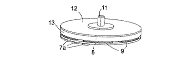
モータの第1の実施形態を図1〜図4を参照して説明する。モータは、非磁性材料、すなわちアルミニウムから形成されたベース部材1を有しており、このベース部材1は、短い中空の円筒体として成形されており、円筒体の外縁部の周囲に延びた2つの肩部2,3と、内室における第3の肩部4とを有している。肩部2は、薄鋼板から裁断されたヨーク5を支持している。ヨーク5は中央リング6と、この中央リング6から半径方向に延びた多数のスポーク7a,7bとから形成されている。図1の手前に面したヨーク5の第1の半分においては、スポーク7aは、残りの半分のスポーク7bよりも短くなっている。長いスポーク7bは、ベース部材1の肩部3によって支持された環状の回路板8の外縁部にまで延びている。回路板8の、ヨーク5とは反対側の上面には6つのコイル9がプリントされている。ベース部材1と、ヨーク5と、回路板8とはモータのステータを形成している。
A first embodiment of a motor will be described with reference to FIGS. The motor has a
ベース部材1の内部の肩部4には、玉軸受10の外レースが支持されている。シャフト11は玉軸受10の内レースに嵌合させられている。玉軸受10は間隙を有している。
An outer race of the ball bearing 10 is supported on the
シャフト11の半径方向フランジは、ロータディスク12と、コイル9に面した磁極を有する輪形磁石13とを有している。回路板の表面に対して垂直なコイル9の磁界軸線は、シャフト11の軸線に対して平行である。
The radial flange of the
技術上知られているように、シャフト11と、ディスク12と、輪形磁石13とから形成されたロータは、コイル9に異なる相の交流電流を供給することによって発生される回転磁界によって駆動され、輪形磁石13と、ロータディスク12と、シャフト11と、玉軸受10と、ベース部材1と、ヨーク5とから形成された磁気回路に磁束を生ぜしめる。
As is known in the art, the rotor formed by the
ヨーク5のスポーク7a及び7bの異なる長さにより、長いスポーク7bを有するセクタにおけるよりも、より短いスポーク7aを有するセクタにおいて空隙の幅がより大きく、ヨーク面積はより小さく、したがって、短いスポーク7aに面した輪形磁石13のセクタによって経験される磁気引力は、長いスポーク7bに面したセクタのものよりも小さい。したがって、モータが動作している時にはいつでも、トルクがロータに提供され、このトルクは、ロータを回転させる角運動量ベクトルに対して垂直な軸線を中心にロータを傾斜させる傾向がある。
Due to the different lengths of the
自由に回転するトップにおいて、このようなトルクは、角運動量ベクトル、ひいてはトップの軸線の変動を生じることが知られている。これは、回転するトップにおいて、トルクベクトルは、トップが傾斜させられる方向と同期して回転し、これにより、トルクベクトルは角運動量ベクトルに対して常に直交方向であるからである。本発明の場合、これに対して、トルクベクトルは回転しないので、玉軸受10の間隙が許容する限りロータ軸線は所定の方向にのみ傾斜する。したがって、シャフト11が揺動するのを許容する間隙にも拘わらず、シャフト11は、コイル9の磁界によって回転するように駆動された場合、所定の位置及び向きを占め、非反復性振れは最少限に低減される。
In a freely rotating top, such torque is known to cause variations in the angular momentum vector and thus the top axis. This is because at the rotating top, the torque vector rotates in synchronism with the direction in which the top is tilted, so that the torque vector is always orthogonal to the angular momentum vector. In the present invention, on the other hand, the torque vector does not rotate, so that the rotor axis is inclined only in a predetermined direction as long as the clearance of the ball bearing 10 allows. Thus, despite the
前記実施形態において、ヨーク5は、ベース部材1の肩部2において支持された内側リング6を有しており、この内側リングからスポーク7a,7bが半径方向外向きに延びている。スポーク7a,7bは長さだけが異なり、断面は同じである。
In the above embodiment, the
択一的に、シャフトの位置及び向きを規定するために必要なフィールド非対称性は、長さは同じであるが断面積が異なるスポーク7a,7bによって生ぜしめられることができる。
Alternatively, the field asymmetry required to define the position and orientation of the shaft can be caused by
別の択一例として、スポークの角度方向間隔が、ヨーク5の第1のセクタと第2のセクタとにおいて異なるように形成されてもよい。
As another alternative example, the angular intervals of the spokes may be formed differently in the first sector and the second sector of the
別の択一例として、スポークは、外側リングによって一片に結合されており、自由端部は半径方向内向きに延びており、ベース部材1の肩部2に支持されている。この場合、渦電流が外側リングから第1のスポーク及びベース部材を通って、第2のスポークを通って外側リングへ戻るのを防止するために、スポークの自由端部とベース部材との間には電気的絶縁層が設けられるべきである。別の択一例は、外側リングによって一片に結合されたスポーク7a及び7bは、ベース部材1まで延びているのではなく、回路板8への結合によって、例えば糊付けによって支持されているだけである。
As another alternative, the spokes are joined together by an outer ring, with the free end extending radially inward and supported on the shoulder 2 of the
モータの第2の実施形態を図5〜図8を参照に説明する。第1の実施形態のモータにおける同一のカウンターパートを有するこのモータのコンポーネントは、これらと同じ参照符号を有しており、再び説明されない。 A second embodiment of the motor will be described with reference to FIGS. Components of this motor having the same counterpart in the motor of the first embodiment have the same reference numerals and are not described again.
この第2の実施形態のモータにおいて、ヨーク5は、規則的な角度方向間隔で内側リングから半径方向外向きに延びた同じ形状のスポーク7を有している。非対称的な磁界成分は、回路板8上のコイル9の間に、金属コア14を有する3つの連続的なコイル9bから形成された1つのグループが設けられており、他のグループを形成した残りの3つのコイル9aは金属コアを有していないということにより、この実施形態において生ぜしめられる。これらの金属コア14は単に、例えば糊付けによって回路板8の表面に固定されることができ、好適には、図6の断面図と図8の底面図とに示したように、金属コアは、回路板8に形成された孔に嵌め込まれている。金属コア14は、コイル9bによって占められた回路板8の半分における空隙幅を減じるためにも有効であり、これにより、この半分において、輪形磁石13は、空のコイル9aを支持した半分におけるよりも強い磁気引力を受ける。第1の実施形態と同様に、磁界の非対称性により、シャフト11は所定の、僅かに傾斜した向きを占める。
In the motor of this second embodiment, the
図9は本発明の第3の実施形態による回路板の底面図である。この実施形態において、一片から成るヨークの代わりに、直接に相互結合されていないが、例えば糊付けによって回路板8の下側に固定された多数の半径方向スポーク7のみが設けられている。図5〜図8の実施形態と同様に、回路板8の上側に形成されたコイルの部分(図示せず)は、回路板8の孔を貫通した金属コア14を有している。スポーク7を回路板8に取り付けるために、個別の部材から電子回路を組み立てるための慣用の技術が使用されることができる。別の択一例は、一体化されたスポーク7を備えた1つのプラスチックヨーク部分8aであることができ、図11によれば、プラスチックヨーク部分は例えば射出成形プロセスによって形成されている。
FIG. 9 is a bottom view of a circuit board according to a third embodiment of the present invention. In this embodiment, instead of a single piece of yoke, only a large number of
第4の実施形態によれば、回路板8に個々に同じスポーク7を配置することにより、図10に示したような回路板を形成することは特に容易であり、この回路板において、磁界非対称性は、回路板8の半分においてスポークを、別の半分におけるよりも小さな角度方向間隔を置いて配置することによって得られる。
According to the fourth embodiment, it is particularly easy to form a circuit board as shown in FIG. 10 by arranging the
磁界非対称性を得るための別のアプローチは図12に示されており、本発明の第5の実施形態による、異なる量の巻線nを備えた、コイル9a、すなわちn巻線を有する図12におけるコイル1,3,5と、コイル9b、すなわちn+x巻線を有する図12におけるコイル2,4,6との、電気接続計画図及び配置計画図を示している。回路板8の半分におけるコイル5,1,3は、他方の半分のコイル4,2,6よりも少ない数の巻線を有しているので、2つのコイルグループに同じ電流が供給されると、図12の接続計画図に示されたように、輪形磁石とコイル9aとの間の磁気引力は、輪形磁石とコイル9bとの間の磁気引力よりも小さい。
Another approach for obtaining the magnetic field asymmetry is shown in FIG. 12, and according to the fifth embodiment of the present invention, FIG. 12 having a coil 9a, ie n windings, with different amounts of winding n. FIG. 13 shows an electrical connection plan diagram and an arrangement plan diagram of
1 ベース部材、 2,3,4 肩部、 5 ヨーク、 6 中央リング、 7 スポーク、 8 回路板、 9 コイル、 10 玉軸受、 11 シャフト、 12 ロータディスク、 13 輪形磁石、 14 金属コア 1 base member, 2, 3, 4 shoulder, 5 yoke, 6 center ring, 7 spoke, 8 circuit board, 9 coil, 10 ball bearing, 11 shaft, 12 rotor disk, 13 ring magnet, 14 metal core
Claims (7)
ステータ(1,5,8)が、軟磁性材料から形成された複数の半径方向に向けられたスポーク(7;7a,7b)を有しており、ステータの第1のセクタにおいて、スポーク(7a)の断面の少なくとも1つが、第2のセクタにおけるスポーク(7b)の断面とは異なっており、
ステータ(1,5,8)の第1のセクタにおいて、コイル(9a)の巻き数が、第2のセクタにおけるコイル(9b)の巻き数とは異なっているか、又は
ステータ(1,5,8)の第1のセクタにおいて、コイル(9b)内の材料(14)の透過性が、第2のセクタにおけるコイル(9a)内の材料の透過性とは異なり、これにより、前記回転磁界に加えて、前記軸線に対して回転方向で非対称な定置の磁界成分を生ぜしめることを特徴とする、電気モータ。 An electric motor is provided with a stator (1, 5, 8) having a gap extending around the axis, and a rotating magnetic field is generated in the stator, and the rotor (11, 12, 13), and the rotor is held by the bearing (10) so as to be rotatable, and is held in the gap, and is rotated about the axis by the rotating magnetic field. In the type having a permanent magnet (13) driven by
The stator (1, 5, 8) has a plurality of radially oriented spokes (7; 7a, 7b) formed from a soft magnetic material, and in the first sector of the stator, the spoke (7a ) At least one of the cross-sections of the spokes (7b) in the second sector,
In the first sector of the stator (1, 5, 8), the number of turns of the coil (9a) is different from the number of turns of the coil (9b) in the second sector, or the stator (1, 5, 8 ), The permeability of the material (14) in the coil (9b) is different from the permeability of the material in the coil (9a) in the second sector. An electric motor that generates a stationary magnetic field component that is asymmetric in the rotational direction with respect to the axis.
Applications Claiming Priority (2)
| Application Number | Priority Date | Filing Date | Title |
|---|---|---|---|
| EP04029314.4 | 2004-12-10 | ||
| EP04029314A EP1670125A1 (en) | 2004-12-10 | 2004-12-10 | Electric motor |
Publications (3)
| Publication Number | Publication Date |
|---|---|
| JP2006174696A JP2006174696A (en) | 2006-06-29 |
| JP2006174696A5 JP2006174696A5 (en) | 2009-01-22 |
| JP4801985B2 true JP4801985B2 (en) | 2011-10-26 |
Family
ID=34927724
Family Applications (1)
| Application Number | Title | Priority Date | Filing Date |
|---|---|---|---|
| JP2005356572A Expired - Fee Related JP4801985B2 (en) | 2004-12-10 | 2005-12-09 | Electric motor |
Country Status (8)
| Country | Link |
|---|---|
| US (1) | US7382077B2 (en) |
| EP (1) | EP1670125A1 (en) |
| JP (1) | JP4801985B2 (en) |
| KR (1) | KR101111673B1 (en) |
| CN (1) | CN1787335B (en) |
| DE (1) | DE602005027799D1 (en) |
| MY (1) | MY140682A (en) |
| TW (1) | TWI370606B (en) |
Families Citing this family (12)
| Publication number | Priority date | Publication date | Assignee | Title |
|---|---|---|---|---|
| DE102007002782A1 (en) * | 2007-01-18 | 2008-07-31 | Siemens Ag | Rotary drive with straight primary section segments |
| TWI425742B (en) * | 2008-11-14 | 2014-02-01 | Metal Ind Res & Dev Ct | Integrated in the electronic device of the motor |
| JP2013183494A (en) * | 2012-02-29 | 2013-09-12 | Sony Corp | Driving motor, image blur correction apparatus, and imaging apparatus |
| CN105990977B (en) * | 2015-02-10 | 2019-08-06 | 苏州捷美电子有限公司 | A kind of magnetic driven rotary device |
| US10020718B2 (en) * | 2015-05-15 | 2018-07-10 | Saqr Majed Bin Saqr Al Marri | Alternator device |
| US11527933B2 (en) * | 2015-10-02 | 2022-12-13 | E-Circuit Motors, Inc. | Stator and rotor design for periodic torque requirements |
| KR102488442B1 (en) * | 2016-01-21 | 2023-01-13 | 현대모비스 주식회사 | Motor apparatus |
| US11831211B2 (en) | 2017-06-05 | 2023-11-28 | E-Circuit Motors, Inc. | Stator and rotor design for periodic torque requirements |
| CN109861461A (en) * | 2017-11-30 | 2019-06-07 | 日本电产株式会社 | Motor and electrical equipment comprising the motor |
| KR101967613B1 (en) * | 2018-10-04 | 2019-08-19 | 주식회사 유닉스엔지니어링 | Rotary type linear actuator |
| WO2020092470A1 (en) * | 2018-11-01 | 2020-05-07 | E-Circuit Motors, Inc. | Stator and rotor design for periodic torque requirements |
| US11799342B2 (en) * | 2020-02-20 | 2023-10-24 | Kohler Co. | Printed circuit board electrical machine |
Family Cites Families (20)
| Publication number | Priority date | Publication date | Assignee | Title |
|---|---|---|---|---|
| GB2139822A (en) * | 1983-05-03 | 1984-11-14 | Caterpillar Tractor Co | Stator for an electromagnetic machine |
| JPS61202153U (en) * | 1985-06-05 | 1986-12-18 | ||
| US4733119A (en) | 1986-09-22 | 1988-03-22 | Shicoh Engineering Co., Ltd. | 1-Phase self-starting disk-type brushless motor with cogging-producing element |
| JPH0510547Y2 (en) | 1986-11-14 | 1993-03-15 | ||
| JP2869064B2 (en) * | 1987-03-11 | 1999-03-10 | ソニー株式会社 | Disk drive |
| US4843268A (en) * | 1987-09-17 | 1989-06-27 | Marketing Systems Of The South, Inc. | Asymmetric field electromagnetic motor |
| JPH0230274A (en) * | 1988-07-20 | 1990-01-31 | Hitachi Ltd | Dynamic video focus device |
| JPH0458065U (en) * | 1990-09-26 | 1992-05-19 | ||
| JPH05146129A (en) * | 1991-11-20 | 1993-06-11 | Canon Inc | Motor |
| JP2992862B2 (en) * | 1994-06-06 | 1999-12-20 | 株式会社三協精機製作所 | Motor device |
| AUPM827094A0 (en) * | 1994-09-20 | 1994-10-13 | Queensland Railways | Open stator axial flux electric motor |
| JPH10243590A (en) * | 1997-02-26 | 1998-09-11 | Canon Inc | Motor coil and motor |
| JP3439318B2 (en) * | 1997-04-18 | 2003-08-25 | 株式会社三協精機製作所 | Brushless motor and manufacturing method thereof |
| JPH1118348A (en) * | 1997-06-20 | 1999-01-22 | Matsushita Electric Ind Co Ltd | Flat face brushless motor |
| JP4082777B2 (en) * | 1998-03-17 | 2008-04-30 | 株式会社日本計器製作所 | Flat fan motor |
| JP2001054270A (en) * | 1999-08-05 | 2001-02-23 | Sankyo Seiki Mfg Co Ltd | Counterposed type motor |
| JP3494174B2 (en) * | 2001-12-21 | 2004-02-03 | 三菱電機株式会社 | Spindle motor for recording medium drive |
| JP2003348786A (en) * | 2002-05-24 | 2003-12-05 | Mabuchi Motor Co Ltd | Small-sized motor |
| CN1469526A (en) * | 2002-07-19 | 2004-01-21 | 谷立志里科技有限公司 | Combined stator structure with flat winding |
| US6847147B2 (en) | 2003-01-29 | 2005-01-25 | Wavecrest Laboratories, Llc | Dynamoelectric machine having windings that differ in wire gauge and number of winding turns |
-
2004
- 2004-12-10 EP EP04029314A patent/EP1670125A1/en not_active Withdrawn
-
2005
- 2005-11-22 DE DE602005027799T patent/DE602005027799D1/en active Active
- 2005-11-29 MY MYPI20055556A patent/MY140682A/en unknown
- 2005-12-07 KR KR1020050118625A patent/KR101111673B1/en not_active IP Right Cessation
- 2005-12-08 US US11/298,207 patent/US7382077B2/en not_active Expired - Fee Related
- 2005-12-09 JP JP2005356572A patent/JP4801985B2/en not_active Expired - Fee Related
- 2005-12-09 TW TW094143496A patent/TWI370606B/en not_active IP Right Cessation
- 2005-12-12 CN CN2005101314064A patent/CN1787335B/en not_active Expired - Fee Related
Also Published As
| Publication number | Publication date |
|---|---|
| KR101111673B1 (en) | 2012-02-17 |
| MY140682A (en) | 2010-01-15 |
| JP2006174696A (en) | 2006-06-29 |
| EP1670125A1 (en) | 2006-06-14 |
| TW200625759A (en) | 2006-07-16 |
| KR20060065506A (en) | 2006-06-14 |
| US20060125342A1 (en) | 2006-06-15 |
| CN1787335A (en) | 2006-06-14 |
| DE602005027799D1 (en) | 2011-06-16 |
| CN1787335B (en) | 2010-05-12 |
| US7382077B2 (en) | 2008-06-03 |
| TWI370606B (en) | 2012-08-11 |
Similar Documents
| Publication | Publication Date | Title |
|---|---|---|
| JP4801985B2 (en) | Electric motor | |
| JP3801642B2 (en) | D. with minimal net radial force and low cogging torque. C. Brushless motor | |
| JP4687871B2 (en) | Axial gap type electric motor | |
| US6982513B2 (en) | Recording disk drive motor, recording disk drive employing the motor, a method of manufacturing a stator used in the recording disk drive motor, and core plate that is used in the manufacture of the stator | |
| US5124863A (en) | Disk drive device having reduced thickness | |
| JP2007014178A (en) | Rotor | |
| US20080018188A1 (en) | Disk storage device with brushless dc drive motor and slide bearing assembly | |
| EP1670126B1 (en) | Electric motor | |
| US5093595A (en) | Spindle motor having reduced torque ripple | |
| JP3543930B2 (en) | Brushless motor and magnetic recording / reproducing device using this brushless motor | |
| US20010019230A1 (en) | Motor having rotational-speed detector | |
| JP2003264955A (en) | Permanent magnet motor | |
| WO2003046911A1 (en) | Spindle motor for hard disk drives | |
| US5907455A (en) | Distributed spindle motor integrated with disc | |
| US5648693A (en) | Disk driving motor with low noise lead wire arrangement for frequency generator | |
| JP4866000B2 (en) | Flywheel | |
| JPH05344701A (en) | Brushless motor | |
| JPH05344674A (en) | Bearing device for motor | |
| EP0433037B1 (en) | Spindle motor and disk drive provided therewith | |
| KR20130095110A (en) | Magnetization structure of motor | |
| KR100896519B1 (en) | Manufacturing method for electromagnet | |
| JPS58159653A (en) | Brushless motor | |
| KR20130052998A (en) | Core of a motor and spindle motor comprising the same | |
| JP2003219600A (en) | Axial gap type motor | |
| JP2002345204A (en) | Spindle motor and method of manufacturing the same |
Legal Events
| Date | Code | Title | Description |
|---|---|---|---|
| A521 | Written amendment |
Free format text: JAPANESE INTERMEDIATE CODE: A523 Effective date: 20081201 |
|
| A621 | Written request for application examination |
Free format text: JAPANESE INTERMEDIATE CODE: A621 Effective date: 20081201 |
|
| A521 | Written amendment |
Free format text: JAPANESE INTERMEDIATE CODE: A821 Effective date: 20100726 |
|
| RD02 | Notification of acceptance of power of attorney |
Free format text: JAPANESE INTERMEDIATE CODE: A7422 Effective date: 20100726 |
|
| A521 | Written amendment |
Free format text: JAPANESE INTERMEDIATE CODE: A821 Effective date: 20100729 |
|
| RD04 | Notification of resignation of power of attorney |
Free format text: JAPANESE INTERMEDIATE CODE: A7424 Effective date: 20100729 |
|
| TRDD | Decision of grant or rejection written | ||
| A01 | Written decision to grant a patent or to grant a registration (utility model) |
Free format text: JAPANESE INTERMEDIATE CODE: A01 Effective date: 20110719 |
|
| A01 | Written decision to grant a patent or to grant a registration (utility model) |
Free format text: JAPANESE INTERMEDIATE CODE: A01 |
|
| A61 | First payment of annual fees (during grant procedure) |
Free format text: JAPANESE INTERMEDIATE CODE: A61 Effective date: 20110808 |
|
| FPAY | Renewal fee payment (event date is renewal date of database) |
Free format text: PAYMENT UNTIL: 20140812 Year of fee payment: 3 |
|
| R150 | Certificate of patent or registration of utility model |
Free format text: JAPANESE INTERMEDIATE CODE: R150 |
|
| LAPS | Cancellation because of no payment of annual fees |