JP4801061B2 - Droplet deposition device - Google Patents
Droplet deposition device Download PDFInfo
- Publication number
- JP4801061B2 JP4801061B2 JP2007519890A JP2007519890A JP4801061B2 JP 4801061 B2 JP4801061 B2 JP 4801061B2 JP 2007519890 A JP2007519890 A JP 2007519890A JP 2007519890 A JP2007519890 A JP 2007519890A JP 4801061 B2 JP4801061 B2 JP 4801061B2
- Authority
- JP
- Japan
- Prior art keywords
- wall
- channel
- fluid pump
- coating
- chamber
- Prior art date
- Legal status (The legal status is an assumption and is not a legal conclusion. Google has not performed a legal analysis and makes no representation as to the accuracy of the status listed.)
- Expired - Fee Related
Links
- 230000008021 deposition Effects 0.000 title claims description 11
- 230000005684 electric field Effects 0.000 claims description 26
- 239000012530 fluid Substances 0.000 claims description 26
- 238000006073 displacement reaction Methods 0.000 claims description 24
- 239000000463 material Substances 0.000 claims description 23
- 238000000576 coating method Methods 0.000 claims description 19
- 239000011248 coating agent Substances 0.000 claims description 18
- 238000000034 method Methods 0.000 claims description 14
- 230000008859 change Effects 0.000 claims description 6
- 230000007935 neutral effect Effects 0.000 claims description 6
- 239000007788 liquid Substances 0.000 claims description 5
- 238000007772 electroless plating Methods 0.000 claims description 3
- 230000008878 coupling Effects 0.000 claims 2
- 238000010168 coupling process Methods 0.000 claims 2
- 238000005859 coupling reaction Methods 0.000 claims 2
- 230000010287 polarization Effects 0.000 description 32
- 239000010410 layer Substances 0.000 description 19
- 238000005452 bending Methods 0.000 description 18
- 229910052451 lead zirconate titanate Inorganic materials 0.000 description 9
- 230000008569 process Effects 0.000 description 8
- 230000008602 contraction Effects 0.000 description 7
- 239000000919 ceramic Substances 0.000 description 5
- 230000000694 effects Effects 0.000 description 5
- 238000007747 plating Methods 0.000 description 5
- 230000008901 benefit Effects 0.000 description 3
- 239000013078 crystal Substances 0.000 description 3
- 238000002161 passivation Methods 0.000 description 3
- RYGMFSIKBFXOCR-UHFFFAOYSA-N Copper Chemical group [Cu] RYGMFSIKBFXOCR-UHFFFAOYSA-N 0.000 description 2
- PXHVJJICTQNCMI-UHFFFAOYSA-N Nickel Chemical compound [Ni] PXHVJJICTQNCMI-UHFFFAOYSA-N 0.000 description 2
- 229910052802 copper Inorganic materials 0.000 description 2
- 239000010949 copper Substances 0.000 description 2
- 229920000052 poly(p-xylylene) Polymers 0.000 description 2
- 230000004044 response Effects 0.000 description 2
- 238000010008 shearing Methods 0.000 description 2
- 239000000758 substrate Substances 0.000 description 2
- VYZAMTAEIAYCRO-UHFFFAOYSA-N Chromium Chemical compound [Cr] VYZAMTAEIAYCRO-UHFFFAOYSA-N 0.000 description 1
- 229910000599 Cr alloy Inorganic materials 0.000 description 1
- 239000004593 Epoxy Substances 0.000 description 1
- 229910021578 Iron(III) chloride Inorganic materials 0.000 description 1
- 229910000990 Ni alloy Inorganic materials 0.000 description 1
- 239000002033 PVDF binder Substances 0.000 description 1
- 239000012790 adhesive layer Substances 0.000 description 1
- BFNBIHQBYMNNAN-UHFFFAOYSA-N ammonium sulfate Chemical compound N.N.OS(O)(=O)=O BFNBIHQBYMNNAN-UHFFFAOYSA-N 0.000 description 1
- 229910052921 ammonium sulfate Inorganic materials 0.000 description 1
- 235000011130 ammonium sulphate Nutrition 0.000 description 1
- 230000003321 amplification Effects 0.000 description 1
- 229910002113 barium titanate Inorganic materials 0.000 description 1
- JRPBQTZRNDNNOP-UHFFFAOYSA-N barium titanate Chemical compound [Ba+2].[Ba+2].[O-][Ti]([O-])([O-])[O-] JRPBQTZRNDNNOP-UHFFFAOYSA-N 0.000 description 1
- 239000011651 chromium Substances 0.000 description 1
- 230000006835 compression Effects 0.000 description 1
- 238000007906 compression Methods 0.000 description 1
- 238000005868 electrolysis reaction Methods 0.000 description 1
- 238000009713 electroplating Methods 0.000 description 1
- 238000005530 etching Methods 0.000 description 1
- 230000005496 eutectics Effects 0.000 description 1
- 238000007641 inkjet printing Methods 0.000 description 1
- 239000011810 insulating material Substances 0.000 description 1
- RBTARNINKXHZNM-UHFFFAOYSA-K iron trichloride Chemical compound Cl[Fe](Cl)Cl RBTARNINKXHZNM-UHFFFAOYSA-K 0.000 description 1
- HFGPZNIAWCZYJU-UHFFFAOYSA-N lead zirconate titanate Chemical compound [O-2].[O-2].[O-2].[O-2].[O-2].[Ti+4].[Zr+4].[Pb+2] HFGPZNIAWCZYJU-UHFFFAOYSA-N 0.000 description 1
- 238000004519 manufacturing process Methods 0.000 description 1
- 230000007246 mechanism Effects 0.000 description 1
- 229910052751 metal Inorganic materials 0.000 description 1
- 239000002184 metal Substances 0.000 description 1
- 238000000465 moulding Methods 0.000 description 1
- -1 nichrome Chemical compound 0.000 description 1
- 229910001120 nichrome Inorganic materials 0.000 description 1
- 229910052759 nickel Inorganic materials 0.000 description 1
- 230000006911 nucleation Effects 0.000 description 1
- 238000010899 nucleation Methods 0.000 description 1
- 238000003199 nucleic acid amplification method Methods 0.000 description 1
- 238000000059 patterning Methods 0.000 description 1
- 239000004033 plastic Substances 0.000 description 1
- 229920003023 plastic Polymers 0.000 description 1
- 229920002981 polyvinylidene fluoride Polymers 0.000 description 1
- LJCNRYVRMXRIQR-OLXYHTOASA-L potassium sodium L-tartrate Chemical compound [Na+].[K+].[O-]C(=O)[C@H](O)[C@@H](O)C([O-])=O LJCNRYVRMXRIQR-OLXYHTOASA-L 0.000 description 1
- 239000010453 quartz Substances 0.000 description 1
- VYPSYNLAJGMNEJ-UHFFFAOYSA-N silicon dioxide Inorganic materials O=[Si]=O VYPSYNLAJGMNEJ-UHFFFAOYSA-N 0.000 description 1
- 235000011006 sodium potassium tartrate Nutrition 0.000 description 1
- 239000011032 tourmaline Substances 0.000 description 1
- 229940070527 tourmaline Drugs 0.000 description 1
- 229910052613 tourmaline Inorganic materials 0.000 description 1
- 238000007704 wet chemistry method Methods 0.000 description 1
Images


Classifications
-
- B—PERFORMING OPERATIONS; TRANSPORTING
- B41—PRINTING; LINING MACHINES; TYPEWRITERS; STAMPS
- B41J—TYPEWRITERS; SELECTIVE PRINTING MECHANISMS, i.e. MECHANISMS PRINTING OTHERWISE THAN FROM A FORME; CORRECTION OF TYPOGRAPHICAL ERRORS
- B41J2/00—Typewriters or selective printing mechanisms characterised by the printing or marking process for which they are designed
- B41J2/005—Typewriters or selective printing mechanisms characterised by the printing or marking process for which they are designed characterised by bringing liquid or particles selectively into contact with a printing material
- B41J2/01—Ink jet
- B41J2/015—Ink jet characterised by the jet generation process
- B41J2/04—Ink jet characterised by the jet generation process generating single droplets or particles on demand
- B41J2/045—Ink jet characterised by the jet generation process generating single droplets or particles on demand by pressure, e.g. electromechanical transducers
-
- B—PERFORMING OPERATIONS; TRANSPORTING
- B41—PRINTING; LINING MACHINES; TYPEWRITERS; STAMPS
- B41J—TYPEWRITERS; SELECTIVE PRINTING MECHANISMS, i.e. MECHANISMS PRINTING OTHERWISE THAN FROM A FORME; CORRECTION OF TYPOGRAPHICAL ERRORS
- B41J2/00—Typewriters or selective printing mechanisms characterised by the printing or marking process for which they are designed
- B41J2/005—Typewriters or selective printing mechanisms characterised by the printing or marking process for which they are designed characterised by bringing liquid or particles selectively into contact with a printing material
- B41J2/01—Ink jet
- B41J2/135—Nozzles
- B41J2/16—Production of nozzles
- B41J2/1621—Manufacturing processes
- B41J2/164—Manufacturing processes thin film formation
-
- B—PERFORMING OPERATIONS; TRANSPORTING
- B41—PRINTING; LINING MACHINES; TYPEWRITERS; STAMPS
- B41J—TYPEWRITERS; SELECTIVE PRINTING MECHANISMS, i.e. MECHANISMS PRINTING OTHERWISE THAN FROM A FORME; CORRECTION OF TYPOGRAPHICAL ERRORS
- B41J2/00—Typewriters or selective printing mechanisms characterised by the printing or marking process for which they are designed
- B41J2/005—Typewriters or selective printing mechanisms characterised by the printing or marking process for which they are designed characterised by bringing liquid or particles selectively into contact with a printing material
- B41J2/01—Ink jet
- B41J2/135—Nozzles
- B41J2/14—Structure thereof only for on-demand ink jet heads
- B41J2/14201—Structure of print heads with piezoelectric elements
- B41J2/14209—Structure of print heads with piezoelectric elements of finger type, chamber walls consisting integrally of piezoelectric material
-
- B—PERFORMING OPERATIONS; TRANSPORTING
- B41—PRINTING; LINING MACHINES; TYPEWRITERS; STAMPS
- B41J—TYPEWRITERS; SELECTIVE PRINTING MECHANISMS, i.e. MECHANISMS PRINTING OTHERWISE THAN FROM A FORME; CORRECTION OF TYPOGRAPHICAL ERRORS
- B41J2/00—Typewriters or selective printing mechanisms characterised by the printing or marking process for which they are designed
- B41J2/005—Typewriters or selective printing mechanisms characterised by the printing or marking process for which they are designed characterised by bringing liquid or particles selectively into contact with a printing material
- B41J2/01—Ink jet
- B41J2/135—Nozzles
- B41J2/16—Production of nozzles
- B41J2/1607—Production of print heads with piezoelectric elements
- B41J2/1609—Production of print heads with piezoelectric elements of finger type, chamber walls consisting integrally of piezoelectric material
Description
本発明はアクチュエータに関し、特に液滴堆積装置のためのアクチュエータに関する。 The present invention relates to an actuator, and more particularly to an actuator for a droplet deposition apparatus.
液滴堆積装置またはインクジェットプリントヘッドは、流体の小さな液滴を基板上に配置することができる。インク以外の他の流体が噴出チャンバに連通するノズルから流体を圧して噴出されるかもしれないが、このような装置をこれ以後インクジェットプリントと呼ぶことにする。噴出チャンバに連通するアクチュエータ(作動部分)は流体を噴出する力を加える。これらのアクチュエータは多くの異なった形態をとるが、2つのカテゴリーのうちの1つに当てはまる傾向がある。第1のものは機械的なもので、電気的パルスがアクチュエータに変形を起こし、そして例えば、静電気的、熱的曲がり、または圧電性の技法を含む。第2のカテゴリーは熱的アクチュエータまたはバブル(泡)アクチュエータ(bubble actuator)であって、流体をその核形成ポイントに持って来るように熱が加えられる。結果としての泡はチャンバ内でインクを加圧し、ノズルを通してそれのいくらかを圧する。 A droplet deposition apparatus or inkjet printhead can place small droplets of fluid on a substrate. Although other fluids other than ink may be ejected from a nozzle communicating with the ejection chamber, such an apparatus will hereinafter be referred to as inkjet printing. An actuator (operating portion) communicating with the ejection chamber applies a force for ejecting the fluid. These actuators take many different forms, but tend to fit in one of two categories. The first is mechanical, and electrical pulses cause the actuator to deform and include, for example, electrostatic, thermal bending, or piezoelectric techniques. The second category is thermal actuators or bubble actuators where heat is applied to bring the fluid to its nucleation point. The resulting bubble pressurizes the ink in the chamber and presses some of it through the nozzle.
圧電性というのは、石英、ロッシェル塩(Rochelle Salt)、およびトルマリンの天然結晶、そしてさらにチタン酸バリウムおよびチタン酸ジルコン酸鉛(Lead Zirconate Titanate:PZT)のようなセラミックス製品を含めた、ある特定の種類の結晶材料の特性である。PVDFのようなある特定のプラスチックも、圧電性特性を示しうる。 Piezoelectricity is a specific term that includes quartz, Rochelle Salt, and natural crystals of tourmaline, and also ceramic products such as barium titanate and lead zirconate titanate (PZT). The characteristics of this kind of crystal material. Certain plastics, such as PVDF, can also exhibit piezoelectric properties.
機械的圧力がこれらの材料の1つに加えられる場合、結晶構造は圧力に比例した電圧を生じる。逆に電界が加えられる場合、その構造は材料の寸法変化を生じつつ形状を変える。 When mechanical pressure is applied to one of these materials, the crystal structure produces a voltage proportional to the pressure. Conversely, when an electric field is applied, the structure changes shape while causing dimensional changes in the material.
所与の品目に対する圧電効果は、圧電性材料のタイプと、機械的および電気的な動作の軸に依存する。ある特定のタイプの圧電性材料(PZTとして知られている)に対して、これらの軸は「分極」の際に決まり、セラミックの圧電性特性と分極電界の方向を生じさせるプロセスがその方向を決定する。 The piezoelectric effect for a given item depends on the type of piezoelectric material and the axes of mechanical and electrical motion. For a particular type of piezoelectric material (known as PZT), these axes are determined during “polarization”, and the process that produces the piezoelectric properties of the ceramic and the direction of the polarization electric field decide.
分極プロセスが完了すると、電圧が印加されている限りは、分極電圧より低い電圧がセラミックの寸法を変える。 When the polarization process is complete, a voltage lower than the polarization voltage changes the dimensions of the ceramic as long as the voltage is applied.
分極電圧と同じ極性を持つ電圧は、分極軸に沿った追加的な膨張と、分極軸に垂直な収縮を引き起こす。反対極性を持った電圧は反対の効果を有している:つまり、分極軸に沿った収縮と分極軸に垂直な膨張である。いずれのケースでも、電圧が電極から除去されると、圧電素子はその分極された寸法に戻る。ある電圧が分極方向に直角な方向に印加されると、圧電素子は厚み剪断または面剪断で移動する。 A voltage having the same polarity as the polarization voltage causes additional expansion along the polarization axis and contraction perpendicular to the polarization axis. A voltage with the opposite polarity has the opposite effect: contraction along the polarization axis and expansion perpendicular to the polarization axis. In either case, when voltage is removed from the electrode, the piezoelectric element returns to its polarized dimensions. When a certain voltage is applied in a direction perpendicular to the polarization direction, the piezoelectric element moves by thickness shearing or surface shearing.
一般には、これらの動作の2つかそれ以上が同時に存在している。ある場合では、1つのタイプの膨張には、お互いに補償し合って体積の変化をもたらさないような他のタイプの収縮が伴う。例えば、プレートの長さの膨張は幅または厚さの等価な収縮によって補償されうる。しかしながら、いくつかの材料では、補償の効果は等しい量のものではなく、正味の体積変化が起こる。いずれの場合も、機械的共振による増幅が含まれない時には、変形は非常に小さい。 In general, two or more of these operations are present simultaneously. In some cases, one type of expansion is accompanied by another type of contraction that compensates for each other and does not result in a change in volume. For example, plate length expansion can be compensated by equivalent shrinkage of width or thickness. However, with some materials, the compensation effect is not equal and a net volume change occurs. In either case, the deformation is very small when amplification due to mechanical resonance is not included.
図1は圧電性材料の標準的な方向を説明している。3つの直交する軸を1、2、および3と称する。分極、または軸3は、常にセラミック中での分極方向と平行にとる。符号4、5、および6は、1、2、および3それぞれの軸の周りの剪断の移動を表す。分極方向は、分極プロセスの際に2つの電極間に印加される強い電界によって構築される。電気的および機械的な数量に関連付けるために二重の下付添え字(例えばdij)を導入する。1番目の下付添え字は加勢方向を与え、2番目のものは系の応答方向を記述する。例えばd33は、電界が分極軸(方向3)に沿っており、歪み(偏差)が同じ軸に沿っている場合に該当する。電界が前記と同じ方向であるが、歪みが1番の軸(分極軸に直角)方向にあるならば、d31が該当する。
FIG. 1 illustrates the standard orientation of piezoelectric materials. The three orthogonal axes are referred to as 1, 2, and 3. The polarization, or
液滴堆積装置または圧電性材料からなる流体ポンプを生産することが、従来の技術で提案されて来た。例えば特許文献1に記載された1つの構成は、お互いに平行に配列された第1および第2の圧電性部分によって形成されてポンプチャネルを提供する。その部分は、電極によって生じた電界と平行に分極方向が存在するように分極される。この電界の印加の下に、圧電性部分はd31とd33の両モードを膨張させ、それによって噴出チャンバの圧力に影響を与える。例えば、d33は、電界が分極軸(方向3)に沿っており、歪み(偏差)が同じ軸に沿っている場合に該当する。電界が前記と同じ方向であるが、歪みが1番の軸(分極軸に直角)方向にあるならば、d31が該当する。
It has been proposed in the prior art to produce fluid pumps consisting of droplet deposition devices or piezoelectric materials. For example, one configuration described in
剪断またはd15モードで動作する共通の壁デバイスが特許文献2に記載されている。チャンバのそれぞれに向かうように、またはそれぞれから離れるように変形できるような単一の変位可能な壁によって2つの隣接する圧力チャンバが分離される。隣接するチャンバの第1のものに向かって壁が変形する場合、このチャンバ内の圧力は増加するが、他方のチャンバ内の圧力は減少する。同様に、第2のチャンバに向かって壁が変形する場合、このチャンバでの圧力は第1のチャンバ内の圧力の対応する減少を伴いつつ増加する。気圧変化は主に、壁の移動によって引き起こされる体積変化に起因する。
共通の壁を提供することにより、チャンバ密度の増加と、所与の数の噴出チャンバに対するプリントヘッドのサイズの縮小が可能となる。しかしながら、それぞれの壁が同時に2つのチャンバに作用するので、それぞれの噴出チャンバから液滴を同時に発射することはできず、それ故このことは液滴が噴出できる割合を減らす。 Providing a common wall allows for increased chamber density and reduced printhead size for a given number of ejection chambers. However, since each wall acts on two chambers simultaneously, it is not possible to fire droplets from each ejection chamber at the same time, thus reducing the rate at which droplets can be ejected.
本発明の目的は、改善された装置を提供し、これらおよび他の問題に対処することを探求することである。 The object of the present invention is to provide an improved device and seek to address these and other problems.
本発明の一局面によれば、配列方向に並んで配置された多くの圧力チャンバを有する液滴堆積のための流体ポンプが提供され、
隣接する圧力チャンバを分離する変位可能な壁であって、前記多くの方向に平行な方向に分極した圧電性材料、および自身に対して電界を印加するための電極手段、を備えた壁、を有し、
その状況で、前記変位可能な壁が前記電極手段の間に印加される電界下に存在可能なように配置され、他の隣接するチャンバにおいて変位された体積とは異なる、一の前記隣接するチャンバの体積を変位させる。
According to one aspect of the invention, there is provided a fluid pump for droplet deposition having a number of pressure chambers arranged side by side in an array direction,
A displaceable wall separating adjacent pressure chambers, comprising a piezoelectric material polarized in a direction parallel to said many directions, and electrode means for applying an electric field to itself; Have
In that situation, one said adjacent chamber which is arranged such that said displaceable wall can exist under an electric field applied between said electrode means and is different from the volume displaced in the other adjacent chamber Displace the volume of.
また、圧力チャンバにおいて変位される体積は流体の対応する体積に置き換わる。好ましくは、この流体は液体の形態であるが、ガス(気体)であってもよい。 Also, the volume displaced in the pressure chamber replaces the corresponding volume of fluid. Preferably, the fluid is in liquid form, but may be a gas (gas).
好ましくは、第2の隣接するチャンバにおいて変位される体積は、実質的に零であり、つまり、その変位は隣接するチャンバの動作に対して深刻な影響を与えないということである。 Preferably, the volume displaced in the second adjacent chamber is substantially zero, that is, the displacement does not have a significant impact on the operation of the adjacent chamber.
変位可能な壁は、好ましくは、その幾何学的な中心からオフセットした(offset:偏った)中立軸を持つように配列される。このような配置が(オフセットされた)中立軸に平行な歪みを受ける場合、曲げモーメントが誘発されて曲げ歪みがもたらされる。変位可能な壁では、壁の一側がその壁の反対側よりも大きな剛性を持つことができる。変位可能な壁の異なる面は、壁のそれぞれの側に塗布されたコーティングによってもたらされた異なる剛性を持っていることが好ましいのであるが、しかしその壁の構造は、例えば一の側に沿って軟化させるノッチを提供することなどにより、中立軸をオフセットさせる代案の方法で適合させることができる。このコーティングは、例えば不動態化(passivation:パッシベーション)機能または電気伝導機能のような、壁の一部を単に増加させる以外の機能的な特徴を持たせることができる。2つ以上の異なるコーティング材料を、壁の一方か両方の側に、重なった配置状態で提供することができる。同じコーティング材料または複数材料を異なる厚さの壁の両側に提供することができ、そして一方あるいはそれぞれの側の厚さを剛性の点で相対的に相違するようにできる。 The displaceable wall is preferably arranged with a neutral axis offset from its geometric center. When such an arrangement is subjected to strain parallel to the (offset) neutral axis, a bending moment is induced resulting in bending strain. With a displaceable wall, one side of the wall can have greater rigidity than the other side of the wall. The different faces of the displaceable wall preferably have different stiffness provided by the coating applied to each side of the wall, but the wall structure is, for example, along one side. Can be accommodated in alternative ways of offsetting the neutral axis, such as by providing a notch for softening. The coating can have functional characteristics other than merely increasing a portion of the wall, such as a passivation function or an electrical conduction function. Two or more different coating materials can be provided in an overlapping arrangement on one or both sides of the wall. The same coating material or multiple materials can be provided on both sides of different thickness walls, and the thickness of one or each side can be relatively different in terms of stiffness.
電極手段は、それらの間に生成される電界が前記多くの方向に平行になるように、好ましくは、壁の対向する面上に位置する電極によって提供される。好ましい実施の態様では、電極は異なった厚さのものであり剛性の相対的な相違を提供する。 The electrode means are preferably provided by electrodes located on opposite faces of the wall so that the electric field generated between them is parallel to the many directions. In a preferred embodiment, the electrodes are of different thicknesses, providing a relative difference in stiffness.
電極は無電解メッキによって形成することができる。方向付け技術、例えば真空メッキを使ってシード層をそれぞれの壁の1つの側に堆積することができる。次にシード層に、適切な無電解プロセスでさらにメッキし、壁の一側にはメッキされ、他側にはメッキされないようになる。次に、それぞれの壁の他側にシード層が堆積され、無電解メッキプロセスが続けられる。この時点で壁の両側がメッキされることになるが、一側の最初の層だけにおいて、異なる厚さが維持されるという結果になる。 The electrode can be formed by electroless plating. A seed layer can be deposited on one side of each wall using a directing technique such as vacuum plating. The seed layer is then further plated with a suitable electroless process so that one side of the wall is plated and the other side is not plated. Next, a seed layer is deposited on the other side of each wall and the electroless plating process continues. At this point, both sides of the wall will be plated, resulting in different thicknesses being maintained only in the first layer on one side.
あるいは、例えば湿式の化学的プロセスを使い、それぞれの壁の両側にシード層を提供することによって電極を形成することができる。次に、第1の組のそれぞれの壁の第1の面を接続し、別に第2の組のそれぞれの壁の第2の面を接続するためにパターニングが行なわれる。次に壁が別々に電気メッキされ、第1の組が第2の組より長い時期メッキされるか、またはその逆のメッキが行なわれる。 Alternatively, the electrodes can be formed by providing seed layers on both sides of each wall, for example using a wet chemical process. Next, patterning is performed to connect the first surface of each wall of the first set and separately connect the second surface of each wall of the second set. The walls are then electroplated separately and the first set is plated for a longer period than the second set, or vice versa.
好ましい実施の態様では、圧力チャンバは実質的に同一である。例えば、それぞれの圧力チャンバは等しい寸法のものであって、流体が噴出されるノズルを貫通させつつ構成することができる。他の実施の態様において、圧力チャンバのいくつかが、液滴がノズルを通って噴出される噴出チャンバのことを指し、一方、残りのチャンバが流体を噴出しないダミーチャンバのことを指す。ダミーチャンバは液体または空気を有しうる。 In a preferred embodiment, the pressure chamber is substantially the same. For example, each pressure chamber may be of the same size and be configured to penetrate a nozzle from which fluid is ejected. In other embodiments, some of the pressure chambers refer to ejection chambers where droplets are ejected through nozzles, while the remaining chambers refer to dummy chambers that do not eject fluid. The dummy chamber can have liquid or air.
ダミーチャンバおよび圧力チャンバは共に配列方向に直角な伸長方向にチャネルを膨張させることができる。 Both the dummy chamber and the pressure chamber can expand the channel in the extending direction perpendicular to the direction of arrangement.
チャネルの上端を覆って伸び、それによってその上端を閉じるようなカバーを提供することができる。一実施の態様では、そのカバーは液滴を噴出するノズルを収容する。他の実施の態様において、ノズルはノズルプレートに形成され、そしてノズルプレートは圧力チャネルの前面に取り付けられる。ダミーチャネルは、その上端表面を閉じるカバーを持っていても、持っていなくてもよい。 A cover can be provided that extends over the top of the channel and thereby closes the top. In one embodiment, the cover contains a nozzle that ejects droplets. In other embodiments, the nozzle is formed in a nozzle plate and the nozzle plate is attached to the front face of the pressure channel. The dummy channel may or may not have a cover that closes its top surface.
上記カバーは剛性のあるものとすることができ、あるいは好ましくは、変位可能な壁の湾曲を可能にするような柔軟性を持たせることができる。例えば柔軟な接着剤層をカバーによって変位可能な壁の上端に固着させることなどにより、柔軟なヒンジを提供することができる。 The cover can be rigid or, preferably, can be flexible so as to allow bending of the displaceable wall. For example, a flexible hinge layer can be provided by securing a flexible adhesive layer to the upper end of a wall that can be displaced by a cover.
モールディング(moulding)やソーイング(sawing)、あるいはそれら2種類の組み合わせでも、流体ポンプを形成できる。 A fluid pump can also be formed by molding, sawing, or a combination of the two.
さて、図1〜図12を参照して、専ら例によって、これから本発明を説明する。 The present invention will now be described by way of example only with reference to FIGS.
図2を参照すると、インクジェットプリンタヘッド10は多数の平行なインクチャネル12を有し、それらは配列を形成し、そしてチャネルの長手方向に垂直な多くの方向にチャネルが隔てられている。チャネルはmm当たり2個以上のチャネル密度で形成される。ラミネート(薄板)加工された圧電性材料のシート14において、ふさわしくはPZTが矢印15,15’の方向に分極され、側壁16と底面によってそれぞれ規定され、PZTの厚さはチャネル深さより厚い。チャネル12は上端が開放され、プリンタヘッドにおいてシート14に対し熱的に加工された絶縁材料からなる上端シート20によって閉じられ、チャネルの底面に平行に配置され、また壁16の上端22に接合されている。それらの側壁と底面上のチャネル12は、金属化された電極層24によって裏打ちされている。従って、類似の大きさであるが反対符号の電圧の差が隣接するそれぞれの2つの壁16の反対側の面上における電極に印加される場合、壁は分極方向15に直角な電界を受ける、ということは明白であろう。その結果、その壁は剪断モードで変形し、破線28で示されるような場所に変位する。
Referring to FIG. 2, the inkjet printer head 10 has a number of
図3において、チャネル12が統一された深さの前方部分を有することが見て取れ、その前方部分は、その前方端においてノズル40を内部に形成したノズルプレート38により閉じられる。そしてノズル40からは、チャネル内のインクの液滴がチャネルの対面するアクチュエータ壁16の付勢によって噴出される。チャネル12は壁16の上端から拡張する浅い深さの部分も有している。壁16の反対側の面上にある金属化メッキ部分24はチャネル側壁の深さを占めるが、チャネルの長さに亘って延在しておらず、プリントヘッドの容量負荷を最小化する。使用された適切な電極金属は、ニッケルとクロムの合金、すなわちニクロムであるか、または無電解メッキニッケルである。電極は、まず、メッキ角度を利用して堆積され、側壁の全深さに電極が堆積することを可能にする。マニホールド(manifold)領域において壁に堆積することを防止するためにマスクが使われる。このステップは繰り返され、それぞれの壁の両側に電極が形成されることを可能にする。第3のステップは、それぞれのチャネルの底部に垂直な堆積によって遂行され、その結果チャネルの底面上に堆積が生じ、マニホールド領域においてはチャネルがラン・アウト(run out)する(逃げる)。
In FIG. 3, it can be seen that the
壁16上のいずれかの側の電極24に適切な波形を印加することによって、液滴はそれぞれのチャネルから噴出される。特に好ましい波形はドロー・リリース・リインフォース(draw-release-reinforce:引き―解放―加勢)波形として知られている。チャンバの外側への境界となっている両方の壁を引くことによって、まず選択されたチャネルの体積を増加させ、そして一定の時間その状態に壁を保持する。その一定の時間が経過した後、選択されたチャネルの体積を減らすように壁が内側に動かされ、それによってノズルを通して液滴が噴出される。それぞれの壁が隣接するチャネルに作用するので、明らかに、隣接するチャネルの両方から同時に液滴を噴出することはできない。液滴が選択されていないチャネルから噴出されないことにも留意すべきである。これら2つの特徴の組み合わせで、液滴をチャネルから噴出できる最大の周波数を減らす。
By applying an appropriate waveform to the
それぞれの活性チャネルの間に「エア・ギャップ(air gap)」を提供することは、図2および図3のプリントヘッドの動作周波数を増やしうる。エア・ギャップは噴出チャネルより狭くできるが、チャネル密度を50%にまで下げることになることがわかる。 Providing an “air gap” between each active channel can increase the operating frequency of the printheads of FIGS. It can be seen that the air gap can be narrower than the ejection channel, but will reduce the channel density to 50%.
アクチュエータの他の形態を、図4を参照しながら説明する。再び、圧電性セラミックの平行な壁によって分離された多数の平行なチャネルが形成される。しかしながら、分極の方向は、図2を参照しながら説明した分極の方向に垂直である。この壁は配列方向に分極され、いずれかの側の壁に提供された電極が極性方向に平行な方向の壁を横切る電界を印加する。チャネル12はPZTの一側に形成され、関係するノズル50を持っている。電極24はチャネルの内部壁上に提供される。
Another embodiment of the actuator will be described with reference to FIG. Again, a number of parallel channels are formed separated by parallel walls of piezoelectric ceramic. However, the direction of polarization is perpendicular to the direction of polarization described with reference to FIG. This wall is polarized in the array direction, and the electrode provided on either side wall applies an electric field across the wall in a direction parallel to the polar direction.
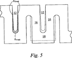
図4のアクチュエータを拡大した図である図5で、より詳細に見ると、駆動電極24も、図3で矢印15によって示すようなPZTを分極させる電界を印加するのに使われる。壁およびベースのいずれかの側にある電極は、同じ厚さのものである。駆動電界が電極間に印加される場合、壁16は点線で表すようにd33方向で厚くなり、d31方向における高さ方向で収縮することになる。これらの方向における所与のチャネルに対する正味の変位をδ31wallおよびδ33wallと命名する。従って、トータルの正味の変位は以下の式によって与えられる:
Viewed in more detail in FIG. 5, which is an enlarged view of the actuator of FIG. 4, the

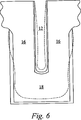
本発明によるアクチュエータを、図6を参照して説明する。圧電性材料は、駆動電極間への分極電界を印加することによって分極される。しかしながら、電極は、噴出チャンバ12の中にあるか外にあるかによって異なる厚さのものである。これは、出願人によって発見されたことであって、壁の反対側に、噴出性能を改善するような異なる剛性を提供する。
An actuator according to the present invention will be described with reference to FIG. The piezoelectric material is polarized by applying a polarization electric field between the drive electrodes. However, the electrodes are of different thicknesses depending on whether they are inside or outside the
異なった剛性が、値δbendingによる体積変位を増加させる曲げモーメントを、アクチュエータ壁に誘起するので、噴出性能は改善される。各々の壁は点線で表すような位置に変位する。従って、トータルの正味の変位は以下の式によって与えられる: Since different stiffness induces a bending moment in the actuator wall that increases the volume displacement due to the value δ bending , the jetting performance is improved. Each wall is displaced to a position represented by a dotted line. Thus, the total net displacement is given by:
しかしながら、ベース18の剛性は壁の曲げ移動を抑制することができ、さらに噴出性能を改善するように設計変更をすることができる。例えばベース中の分極方向を逆にしたり、ベースの厚さを減少したりできる。 However, the rigidity of the base 18 can suppress the bending movement of the wall, and the design can be changed to further improve the ejection performance. For example, the direction of polarization in the base can be reversed or the thickness of the base can be reduced.
例えば、さらに薄いベースが提供される場合の偏差を図7に表す。δbendingは増加して全体的な体積変位は改善される。 For example, the deviation when a thinner base is provided is shown in FIG. δ bending is increased and the overall volume displacement is improved.
圧電性材料の膨張と収縮によって変位した体積、および曲げ移動によって変位した体積は、特に、圧電性材料の反対側の面上に提供された異なった剛性によって曲げが誘発される状況で、共に機能することができ、チャンバ中のトータルの正味の体積変位を増加または減少させる、ということが出願人によってさらに認識された。 Volumes displaced by expansion and contraction of piezoelectric material and volumes displaced by bending movement work together, especially in situations where bending is induced by the different stiffness provided on the opposite surface of the piezoelectric material. It has been further recognized by the Applicant that it is possible to increase or decrease the total net volume displacement in the chamber.
別々のメッキ部分が逆であれば、曲げは反対方向に起き、変位δ31wallおよびδ33wallは反対になり、チャンバ中の正味の体積変位は以下で与えられる: If the separate plated parts are reversed, the bending occurs in the opposite direction, the displacements δ 31wall and δ 33wall are reversed, and the net volume displacement in the chamber is given by:
δbendingに対する適切な値を選択し、機能させることによって、δbending=δ33+δ31の下に、チャネル中の正味の体積変位が実質的にない状態でアクチュエータを動作させることが可能である。 select the appropriate value for [delta] Bending, by function, under δ bending = δ 33 + δ 31 , the volume displacement of the net in the channel it is possible to operate the actuator in a state substantially free.
好都合に、この状態で、またはこれに近い状態で働かせることによって、あらゆるチャネルが同時に液滴を噴出するよう作動させることのできる、共通壁の液滴堆積装置を提供することが可能である。 Conveniently, by working in or near this state, it is possible to provide a common wall droplet deposition apparatus that can be operated to cause all channels to eject droplets simultaneously.
それぞれのチャネルに対してただ1つの壁を作動させることによって、これは達成できるが、図8において変位した壁の形状を破線で示している。この配置においては、それぞれの壁の別々のメッキ部分は同じ「方向」にあり、示されたように、右手の薄いメッキ部分1102と左手の厚いメッキ部分1104である。この配置においては、それぞれのチャネルは一つの壁の偏差によって作動させられる。チャネル1108の作動は壁1106の偏差のみによって達成される。1つの壁だけが撓むが、チャネルにおける正味の変位は圧電性の膨張/収縮と曲げ効果の合計である。上記で説明したように、壁1106の作動は実質的にチャネル1112のいかなる正味の変位をも起こさない。従って、隣接するチャネル1112は、チャネル1108とは実質的に独立して作動できる(すなわち、もし必要ならば、これらの2つの隣接するチャネルが同時に作動できる)、ということが理解できるであろう。
Although this can be achieved by actuating only one wall for each channel, the displaced wall shape is shown in dashed lines in FIG. In this arrangement, the separate plated portions of each wall are in the same “direction”, as shown, a thin plated
示されたように生じる曲げのために、この構造は、その場所で必要な壁回転が可能なように、壁の上端または底面(あるいはその両方)において十分に従順であるべきである。例えば、上端プレート1114は十分に追従可能な材料から作ることができる。あるいは、壁が上端または底面プレートと出会うところに機械的ヒンジを使用することができる。
Because of the bending that occurs as shown, this structure should be sufficiently compliant at the top and / or bottom of the wall so that the necessary wall rotation is possible at that location. For example, the
隣接するチャネルの同時作動を可能にする他の壁構造を図9から図12に示す。これらの図のそれぞれは、2つのチャネルを規定する3つの壁を表す。壁に対する分極パターンは左側の壁において矢印で示すが、電極配置および適用される駆動信号に応じて、同じ作動形態を達成するために別の分極形態も可能である。いかなる場合の作動も、壁または壁部分を横切る(示されたように左から右、または右から左への)電界の印加による。中央の壁は、その作動させられた形状、すなわち左側のチャネルにおける正味の変位を起こし、実質的には右側のチャネルに正味の変位を起こさないような壁変形、を示している。これらの図にはノズルは示していないが、チャネルの最上部またはチャネル端部に位置することができる。 Other wall structures that allow simultaneous operation of adjacent channels are shown in FIGS. Each of these figures represents three walls that define two channels. The polarization pattern for the wall is indicated by an arrow in the left wall, but other polarization configurations are possible to achieve the same mode of operation, depending on the electrode placement and the applied drive signal. Operation in any case is by application of an electric field across the wall or wall portion (left to right or right to left as shown). The middle wall shows its actuated shape, that is, a wall deformation that causes a net displacement in the left channel and substantially no net displacement in the right channel. The nozzles are not shown in these figures, but can be located at the top of the channel or at the end of the channel.
図9において、チャネル壁1202の下の部分はいわゆる直接モードで動作し、印加された電界と分極は壁のその部分の膨張を起こす同じ方向になる。壁1204と1206の2つの上の部分は、印加された電界に垂直な反対の方向に分極され、作動時にシェブロン(chevron)のような形状を引き起こす剪断状態で動作する。作動時に、部分1202が膨張してチャネル1220と1230の両方の体積の収縮を引き起こすことがわかる。しかしながら、上の部分1204と1206のシェブロン形状はチャネル1220の体積の収縮と、チャネル1230の体積の増加を引き起こす。チャネル1230の変位はお互いに打ち消すようにようにされ、それによって実質的にチャネル1230の体積の正味の変化を起こさず、一方、チャネル1220の変位は増加され、そのチャネルからの液滴噴出を起こさせる。この実施形態においては、壁の高さ全体を横切る単一の電解の印加によって作動がもたらされる。
In FIG. 9, the lower part of the
好ましい実施形態においては、部分1204と1206の機能と均衡するために直接モードの壁部1202が強化した機能を持つことが必要となるであろう。この部分を横切る一層大きな電界、高機能の圧電性材料、この部分に対するさらに高い高さの壁、またはこれらのいずれかの組み合わせを使うことによって、これを達成することができる。あるいは、またはさらに、チャネルのベースまたは最上部に直接モード動作を適用することができる。しかし、直接モードで動作している壁部の高さの収縮がベース部1240の偏差をもたらす傾向があり、隣接する両方のチャネルにいくらかの変位を起こす、ということがわかる。
In the preferred embodiment, it would be necessary for the
図10を参照すると、上の壁部1304と1306は図9を参照して上記で説明したように、同じ方法で動作する。壁の下の部分は、ギャップ1312によって分離された、シェブロンのような2組の作動部分1308と1310から形成される。このギャップはインクまたは空気で満たすことができる。作動時に、下の部分1308と1310は反対の方向に曲がり、隣接する両方のチャネル1320と1330で体積収縮を起こす。図9と同様に、チャネル1320の作動がチャネル1330中の正味の体積変化を実質的に起こさないように、この構造を配列させることができる。この構造は、図9よりも複雑であって、ノズルピッチの増加をもたらし、さらに低い解像力をもたらすかもしれない。しかしながら、剪断モード動作は、通常、直接モード動作よりも長いライフサイクル(life cycle)を有し、そのために剪断モード動作だけを使う実施形態における利点が存在する。
Referring to FIG. 10, the
このような「二重壁」構造においては、通常、電極はそれぞれの壁の外側の面と内側の面の両方に形成され、そして壁の分極の方向は電極がどのように接続されるか、また駆動信号がどのように印加されるかに依存することになる。このような配置は、壁の高さまでの途中部分に途切れた部分のある電極層を含むことができる。 In such a “double wall” structure, the electrodes are typically formed on both the outer and inner surfaces of each wall, and the direction of wall polarization determines how the electrodes are connected, It also depends on how the drive signal is applied. Such an arrangement can include an electrode layer with a break in the middle up to the height of the wall.
図11の壁構造の下の部分に対しては、ギャップ1512によって分離された、シェブロンのような2組の作動部分1508と1510を再び使用する。上の部分1516は、同じ方向に分極したPZTの単一部分から形成される。それは、上の部分を横切る電界の印加の際に、半分のシェブロン配置のように剪断モードで変形する。これは片持ち(カンチレバー)のように振舞い、壁の中心を横方向に変異させ、壁の下の部分で類似の横方向の変位を引き起こす。下の部分1508と1510は、前述のように外側にシェブロンを拡大するように変位するが、さらにそれらに重ね合わせられる剪断または傾斜を有する。
For the lower part of the wall structure of FIG. 11, two sets of working
なお、図11の実施形態においては、チャネルの上端における部材1518は比較的剛性を有し、片持ちとして振舞う部分1516により誘起される曲げモーメントに対して抵抗をもつべきである。
In the embodiment of FIG. 11, the
図12の実施形態は、印加された電界に垂直な反対方向に分極した壁部1604と1606を使用し、動作の際にシェブロンに変形する。これらの部分は、図12および図13で説明したものと実質的に同じであるが、ただここでは、それらは壁の上端の部分ではなくむしろ底に対して使用される。壁の上端は二重壁の形態をとっており、空胴(キャビティ)によって分離された壁部1608と1610を持っている。部分1608と1610は、それぞれ印加される電界と垂直な単一の分極方向をもつが、反対方向に分極される(例えば電極を使用した分極により達成できる)。作動時には、これらの部分は、それぞれ反対の外方向に傾斜する片持ちとして動作する。この変形を可能にするために、カバーまたはノズルプレートとすることのできる部材1618が、ある特定の実施形態において一定のコンプライアンス(compliance:弾力性)の度合を示すことを要求される、ということが理解される。
The embodiment of FIG. 12 uses oppositely polarized
図8から図12の実施形態が、すべて2つの異なった動作モードを使用する、ということが理解される。その一つは、2つの隣接するチャネルの同じ符号の変位(すなわち両方のチャネルの体積を減らすか、両方のチャネルの体積を増やすこと)を起こし、もう一つは、2つの隣接するチャネルの反対符号の変位(すなわち一方の体積を減らし、他方の体積を増やすこと)を起こす。図8においては、異なった2つの作動モードは同じ壁部、すなわち2つの異なった偏差モードを受ける一つの動作表面、に重ね合わせられる。図9〜図12においては、2つの作動モードは、異なる動作モードを持った異なる壁部から由来すると考えることができる。図11においては、壁の上下の部分は、異なる動作モードに関係する異なる構造を持っているが、しかし上述のように下の部分における動作モードのいくつかの重ね合わせが存在する。 It will be appreciated that the embodiments of FIGS. 8-12 all use two different modes of operation. One causes the same sign displacement of two adjacent channels (ie, reduces the volume of both channels or increases the volume of both channels), the other is the opposite of two adjacent channels A sign displacement (ie, reducing one volume and increasing the other) occurs. In FIG. 8, two different operating modes are superimposed on the same wall, ie one working surface that receives two different deviation modes. 9-12, the two modes of operation can be considered to come from different walls with different modes of operation. In FIG. 11, the upper and lower parts of the wall have different structures relating to different operating modes, but there are some superpositions of operating modes in the lower part as described above.
多くの異なった作動モードの組み合わせを説明してきたけれども、さらなる組み合わせも可能である、ということが理解できる。 Although many different combinations of operating modes have been described, it can be appreciated that further combinations are possible.
さて、部品を製造する方法を図8を参照しながら説明する。まず、PZTタイルおよび基板サポートを一緒にラミネート加工する。チャネル1108、1112などをソーイング(saw:のこ切断)し、シード(種)メッキを塗布する。このメッキをパターンニングし、電気メッキによって電極を形成する。パッシベーション・コーティングを電極上に塗布し、その次に圧電性材料を分極させる。壁の強い動作に応じて低い程度に分極されるように、それぞれの壁を、アクチュエータの動作の均一な変化が一定になるような別々のレベルに分極させることができる。このプロセスの後の方において分極させることの利益は、高温のプロセスを利用できるということである。
Now, a method for manufacturing a component will be described with reference to FIG. First, the PZT tile and the substrate support are laminated together. The
特に好ましいパッシベーションの形態は、ファラデー遮蔽(Faraday Cage:ファラデー・ケージ)である。ファラデー遮蔽は、例えば電極上に非電導層が堆積される場合で、電気伝導性の層が非電導層の上に堆積される場合に作られる。 A particularly preferred form of passivation is the Faraday Cage. A Faraday shield is created, for example, when a non-conductive layer is deposited on an electrode and an electrically conductive layer is deposited on the non-conductive layer.
好ましくは、それぞれの層はコンフォーマル(conformal)であって、アクチュエータ全体を覆う。ノズルは、適切な取り付け機構、例えばエポキシ、熱圧縮、共晶、陽極法などを使って外側の電気伝導層に取り付ける。 Preferably, each layer is conformal and covers the entire actuator. The nozzle is attached to the outer electrically conductive layer using a suitable attachment mechanism such as epoxy, thermal compression, eutectic, anodic methods, and the like.
ノズルプレート接続は、外側の電気伝導層はエッチングされるが内側の絶縁層を残すようなプロセスによって再加工することもできる。例えば、絶縁層をパリレン(parylene)とし、外側の電導層を銅とすることができる。塩化第二鉄または硫酸アンモニウムのいずれかによるエッチング液を、パリレンの影響なしに銅を急速にエッチングするのに使うことができる。 The nozzle plate connection can also be reworked by a process that etches the outer electrically conductive layer but leaves the inner insulating layer. For example, the insulating layer can be parylene and the outer conductive layer can be copper. Etchants with either ferric chloride or ammonium sulfate can be used to rapidly etch copper without the effects of parylene.
エッチングが完了すると、ノズルプレートを解放し、再加工か取り替えが自由にできる。次に、新たな外側の電気伝導層を絶縁層上に堆積し、続いて取替えノズルプレートを取り付ける。 When etching is complete, the nozzle plate is released and can be freely reworked or replaced. A new outer electrically conductive layer is then deposited on the insulating layer, followed by the replacement nozzle plate.
例えばスピーカ(拡声器)などのような他のアクチュエータを提供するために、本発明を利用ことも可能である。スピーカのために本発明のアクチュエータを使うことの一つの特別な利益は、アクチュエータの正味の変位が反対側で顕著でないので、逆向きに反射される音が実質的にない、ということである。 The present invention can also be used to provide other actuators such as speakers (loudspeakers), for example. One particular benefit of using the actuator of the present invention for a speaker is that the net displacement of the actuator is not noticeable on the opposite side, so there is virtually no sound reflected back.
10 インクジェットプリンタヘッド
12 チャネル(噴出チャンバ)
14 シート
15 分極方向
16 壁
18 ベース
20 上端シート
22 上端
24 電極(金属化メッキ部分)
38 ノズルプレート
40 ノズル
50 ノズル
1102、1104 メッキ部分
1106 壁
1108、1112 チャネル
1114 上端プレート
1202、1204 壁
1220、1230 チャネル
1240 ベース部
1304、1306 壁
1308、1310 作動部分
1312 ギャップ
1320、1330 チャネル
1508、1510 作動部分
1512 ギャップ
1518 チャネルの上端における部材
1604、1606 壁
1608、1610 壁
1618 カバー(またはノズルプレート)
10
14
38
Claims (16)
隣接する第1及び第2の圧力チャンバを分離する変位可能な壁であって、前記配列方向に平行な方向に分極した圧電性材料、および自身に対して電界を印加するための電極手段、を備えた壁と、を有し、
その状況で、前記変位可能な壁は、前記電極手段の間に印加される電界下に存在可能なように、その幾何学的な中心からオフセットした中立軸を有しており、他の第2の隣接するチャンバにおいて変位された体積とは異なる、一の第1の前記隣接するチャンバの体積を変位させる
ことを特徴とする液滴堆積のための流体ポンプ。An array of pressure chambers arranged side by side, said array extending in the array direction;
A displaceable wall separating adjacent first and second pressure chambers, wherein the piezoelectric material is polarized in a direction parallel to the arrangement direction, and electrode means for applying an electric field to itself; A wall with
In that situation, the displaceable wall has a neutral axis offset from its geometric center so that it can exist under an electric field applied between the electrode means, and the other second Displacement of the volume of one first said adjacent chamber that is different from the volume displaced in the adjacent chamber of the fluid pump.
前記チャネルは、該チャネルの前記長手方向に延在すると共に、さらに前記長手方向に垂直でかつ前記配列方向に垂直な方向に延在するそれぞれの側壁を持ち、
それぞれのノズルが液体の液滴の噴出のために前記チャネルと連通し、
前記チャネルを堆積液体の液滴ソースに連結させるための連結手段と、選択された任意のチャネルの作動に際して、前記選択されたチャネルの側壁の少なくとも一部に、前記配列方向に一様に平行な横方向変位をもたらす前記チャネルに関連して位置された電気的作動手段であって、前記選択されたチャネルの側壁の少なくとも一部は少なくとも前記チャネルの長手方向の要部に延在している電気的作動手段と、を備えており、
それによって自身に連通するノズルからの液滴噴出をもたらすように内部の圧力変化を起こさせ、
その状況で、コーティングが前記電気的に作動可能な手段の対向する面に塗布され、前記コーティングがそれぞれの面に異なった正味の剛性を提供することを特徴とする液滴堆積装置。An electrical pulsed droplet deposition apparatus having a high density multi-channel array and having a number of parallel channels separated from each other in an array direction perpendicular to the longitudinal direction of the channel,
The channel extends in the longitudinal direction of the channel, and further has respective sidewalls extending in a direction perpendicular to the longitudinal direction and perpendicular to the arrangement direction,
Each nozzle communicates with the channel for ejection of a liquid droplet,
A coupling means for coupling the channel to a drop source of deposition liquid and, in operation of any selected channel, at least a portion of the side wall of the selected channel that is uniformly parallel to the array direction. Electrical actuating means positioned in relation to the channel for effecting a lateral displacement, wherein at least a part of the side wall of the selected channel extends at least in a longitudinal part of the channel An actuating means,
This causes an internal pressure change to cause droplet ejection from a nozzle communicating with itself,
In that situation, a coating is applied to the opposing surfaces of the electrically actuatable means, the coating providing a different net stiffness on each surface.
第1および第2の面を有する圧電性材料の塊を提供する段階と、
前記第1および第2の面上に導電性コーティングを形成する段階であって、前記第1の面上の導電性コーティングが前記第2の面上の導電性コーティングより剛性が高いようにする段階と、
二つの圧力チャンバを形成する段階であって、前記圧電性材料の塊が前記二つの圧力チャンバを分離し、前記第1および第2の面のそれぞれは前記二つの圧力チャンバのそれぞれ1つと隣接している段階と、
を有することを特徴とする方法。A method of forming an actuator for a fluid pump device comprising:
Providing a mass of piezoelectric material having first and second surfaces;
Forming a conductive coating on the first and second surfaces, such that the conductive coating on the first surface is more rigid than the conductive coating on the second surface; When,
Forming two pressure chambers, wherein the mass of piezoelectric material separates the two pressure chambers, each of the first and second surfaces being adjacent to each one of the two pressure chambers; And the stage
A method characterized by comprising:
Applications Claiming Priority (3)
| Application Number | Priority Date | Filing Date | Title |
|---|---|---|---|
| GB0415529.7 | 2004-07-10 | ||
| GBGB0415529.7A GB0415529D0 (en) | 2004-07-10 | 2004-07-10 | Droplet deposition apparatus |
| PCT/GB2005/002746 WO2006005952A2 (en) | 2004-07-10 | 2005-07-11 | Droplet deposition apparatus |
Publications (3)
| Publication Number | Publication Date |
|---|---|
| JP2008505781A JP2008505781A (en) | 2008-02-28 |
| JP2008505781A5 JP2008505781A5 (en) | 2010-02-25 |
| JP4801061B2 true JP4801061B2 (en) | 2011-10-26 |
Family
ID=32865808
Family Applications (1)
| Application Number | Title | Priority Date | Filing Date |
|---|---|---|---|
| JP2007519890A Expired - Fee Related JP4801061B2 (en) | 2004-07-10 | 2005-07-11 | Droplet deposition device |
Country Status (12)
| Country | Link |
|---|---|
| US (1) | US7780273B2 (en) |
| EP (1) | EP1809480B1 (en) |
| JP (1) | JP4801061B2 (en) |
| KR (1) | KR20070032811A (en) |
| CN (1) | CN101107128A (en) |
| AU (1) | AU2005261498A1 (en) |
| BR (1) | BRPI0513219A (en) |
| CA (1) | CA2573041A1 (en) |
| GB (1) | GB0415529D0 (en) |
| IL (1) | IL180533A0 (en) |
| RU (1) | RU2007105101A (en) |
| WO (1) | WO2006005952A2 (en) |
Families Citing this family (7)
| Publication number | Priority date | Publication date | Assignee | Title |
|---|---|---|---|---|
| JP2012148428A (en) * | 2011-01-17 | 2012-08-09 | Toshiba Tec Corp | Method of manufacturing inkjet head |
| JP2012192629A (en) * | 2011-03-16 | 2012-10-11 | Toshiba Tec Corp | Inkjet head and method of manufacturing the same |
| FR2990055B1 (en) | 2012-04-30 | 2014-12-26 | Total Sa | MATRIX FOR DEPOSITING AT LEAST ONE CONDUCTIVE FLUID ON A SUBSTRATE, AND DEVICE COMPRISING SAID MATRIX AND DEPOSITION METHOD |
| JP6069967B2 (en) * | 2012-08-31 | 2017-02-01 | セイコーエプソン株式会社 | Liquid ejection device |
| GB2546097B (en) | 2016-01-08 | 2020-12-30 | Xaar Technology Ltd | Droplet deposition head |
| CN108698403B (en) * | 2016-02-24 | 2020-08-21 | 柯尼卡美能达株式会社 | Ink jet recording apparatus and method of driving ink jet head |
| GB2564634B (en) | 2017-05-12 | 2021-08-25 | Xaar Technology Ltd | A piezoelectric solid solution ceramic material |
Citations (3)
| Publication number | Priority date | Publication date | Assignee | Title |
|---|---|---|---|---|
| JPH1086369A (en) * | 1996-08-27 | 1998-04-07 | Topaz Technol Inc | Ink jet printing head |
| JP2002096476A (en) * | 2000-09-20 | 2002-04-02 | Sharp Corp | Piezoelectric element unit and its manufacturing method, and ink-jet head using piezoelectric element unit |
| JP2004142310A (en) * | 2002-10-25 | 2004-05-20 | Sharp Corp | Inkjet recording head |
Family Cites Families (12)
| Publication number | Priority date | Publication date | Assignee | Title |
|---|---|---|---|---|
| EP0268204B1 (en) | 1986-11-14 | 1991-09-18 | Qenico AB | Piezoelectric pump |
| US4879568A (en) | 1987-01-10 | 1989-11-07 | Am International, Inc. | Droplet deposition apparatus |
| JP2756159B2 (en) | 1989-11-09 | 1998-05-25 | 松下電器産業株式会社 | Ink recording device |
| US5227813A (en) | 1991-08-16 | 1993-07-13 | Compaq Computer Corporation | Sidewall actuator for a high density ink jet printhead |
| JP3047661B2 (en) | 1993-02-16 | 2000-05-29 | ブラザー工業株式会社 | Droplet ejector |
| JP2854508B2 (en) | 1993-08-27 | 1999-02-03 | 株式会社テック | Ink jet printer head and driving method thereof |
| US5480095A (en) | 1993-09-14 | 1996-01-02 | Minnesota Mining And Manufacturing Company | Actuator and container for dispensing fluids |
| JP3183010B2 (en) * | 1993-12-24 | 2001-07-03 | ブラザー工業株式会社 | Ink jet device |
| JP3135800B2 (en) * | 1994-10-20 | 2001-02-19 | 株式会社沖データ | Ink jet head and method of manufacturing the same |
| JP3257960B2 (en) * | 1996-12-17 | 2002-02-18 | 富士通株式会社 | Inkjet head |
| US6020905A (en) | 1997-01-24 | 2000-02-01 | Lexmark International, Inc. | Ink jet printhead for drop size modulation |
| CN1182966C (en) | 1999-08-14 | 2005-01-05 | 萨尔技术有限公司 | Droplet deposition apparatus |
-
2004
- 2004-07-10 GB GBGB0415529.7A patent/GB0415529D0/en not_active Ceased
-
2005
- 2005-07-11 US US11/631,909 patent/US7780273B2/en not_active Expired - Fee Related
- 2005-07-11 CN CNA2005800232722A patent/CN101107128A/en active Pending
- 2005-07-11 EP EP05761560.1A patent/EP1809480B1/en not_active Not-in-force
- 2005-07-11 AU AU2005261498A patent/AU2005261498A1/en not_active Abandoned
- 2005-07-11 KR KR1020077003210A patent/KR20070032811A/en not_active Application Discontinuation
- 2005-07-11 JP JP2007519890A patent/JP4801061B2/en not_active Expired - Fee Related
- 2005-07-11 WO PCT/GB2005/002746 patent/WO2006005952A2/en active Application Filing
- 2005-07-11 RU RU2007105101/12A patent/RU2007105101A/en not_active Application Discontinuation
- 2005-07-11 BR BRPI0513219-3A patent/BRPI0513219A/en not_active IP Right Cessation
- 2005-07-11 CA CA002573041A patent/CA2573041A1/en not_active Abandoned
-
2007
- 2007-01-03 IL IL180533A patent/IL180533A0/en unknown
Patent Citations (3)
| Publication number | Priority date | Publication date | Assignee | Title |
|---|---|---|---|---|
| JPH1086369A (en) * | 1996-08-27 | 1998-04-07 | Topaz Technol Inc | Ink jet printing head |
| JP2002096476A (en) * | 2000-09-20 | 2002-04-02 | Sharp Corp | Piezoelectric element unit and its manufacturing method, and ink-jet head using piezoelectric element unit |
| JP2004142310A (en) * | 2002-10-25 | 2004-05-20 | Sharp Corp | Inkjet recording head |
Also Published As
| Publication number | Publication date |
|---|---|
| EP1809480A2 (en) | 2007-07-25 |
| IL180533A0 (en) | 2007-06-03 |
| CN101107128A (en) | 2008-01-16 |
| CA2573041A1 (en) | 2006-01-19 |
| EP1809480B1 (en) | 2016-06-29 |
| WO2006005952A2 (en) | 2006-01-19 |
| WO2006005952A3 (en) | 2007-07-12 |
| KR20070032811A (en) | 2007-03-22 |
| US7780273B2 (en) | 2010-08-24 |
| GB0415529D0 (en) | 2004-08-11 |
| RU2007105101A (en) | 2008-08-20 |
| AU2005261498A1 (en) | 2006-01-19 |
| JP2008505781A (en) | 2008-02-28 |
| US20080117260A1 (en) | 2008-05-22 |
| BRPI0513219A (en) | 2008-04-29 |
Similar Documents
| Publication | Publication Date | Title |
|---|---|---|
| JP4801061B2 (en) | Droplet deposition device | |
| JP4758600B2 (en) | Double-acting thermal actuator and operating method thereof | |
| CN108472958B (en) | Droplet deposition head and actuator component therefor | |
| JPH05301342A (en) | Ink jet printing head | |
| KR20080034147A (en) | Droplet deposition apparatus | |
| JP2006150948A (en) | Liquid transfer device | |
| US7111927B2 (en) | Piezoelectric vibrator unit | |
| EP1575777A2 (en) | Droplet deposition apparatus | |
| JP4494880B2 (en) | Driving method of piezoelectric ink jet head | |
| EP1329318A2 (en) | Fluid ejecting device with drop volume modulation capabilities | |
| WO2001072520A1 (en) | Multiple-nozzle ink-jet head and method of manufacture thereof | |
| JP4269608B2 (en) | Ink jet head and ink jet recording apparatus having the same | |
| WO1999001283A1 (en) | Ink jet recording head and method of manufacturing the same | |
| JP2009029012A (en) | Liquid jetting head and liquid jet apparatus | |
| JP2007276151A (en) | Inkjet printer head | |
| JP2008126583A (en) | Inkjet head | |
| JP2004284194A (en) | Piezoelectric element, ink jet head and ink jet recording device as well as manufacturing method for ink jet head | |
| JP3804415B2 (en) | Inkjet recording head | |
| JP3514407B2 (en) | Ink jet head and ink jet recording apparatus | |
| JP2002359410A (en) | Piezoelectric transducer and droplet spraying device using the same | |
| JP2002347246A (en) | Ink jet recording head | |
| JP2006069206A (en) | Process for manufacturing liquid ejection head | |
| JPH0985949A (en) | Ink jet recording head and manufacture | |
| JP2007168110A (en) | Method for manufacturing liquid ejection head | |
| WO2001072521A1 (en) | Bimorph actuator, ink-jet head using bimorph actuator, and method of manufacture thereof |
Legal Events
| Date | Code | Title | Description |
|---|---|---|---|
| A977 | Report on retrieval |
Free format text: JAPANESE INTERMEDIATE CODE: A971007 Effective date: 20090302 |
|
| A131 | Notification of reasons for refusal |
Free format text: JAPANESE INTERMEDIATE CODE: A131 Effective date: 20090908 |
|
| A601 | Written request for extension of time |
Free format text: JAPANESE INTERMEDIATE CODE: A601 Effective date: 20091208 |
|
| A602 | Written permission of extension of time |
Free format text: JAPANESE INTERMEDIATE CODE: A602 Effective date: 20091215 |
|
| A524 | Written submission of copy of amendment under article 19 pct |
Free format text: JAPANESE INTERMEDIATE CODE: A524 Effective date: 20100108 |
|
| A131 | Notification of reasons for refusal |
Free format text: JAPANESE INTERMEDIATE CODE: A131 Effective date: 20100713 |
|
| A601 | Written request for extension of time |
Free format text: JAPANESE INTERMEDIATE CODE: A601 Effective date: 20101007 |
|
| A602 | Written permission of extension of time |
Free format text: JAPANESE INTERMEDIATE CODE: A602 Effective date: 20101015 |
|
| A521 | Request for written amendment filed |
Free format text: JAPANESE INTERMEDIATE CODE: A523 Effective date: 20110113 |
|
| A131 | Notification of reasons for refusal |
Free format text: JAPANESE INTERMEDIATE CODE: A131 Effective date: 20110301 |
|
| A521 | Request for written amendment filed |
Free format text: JAPANESE INTERMEDIATE CODE: A523 Effective date: 20110601 |
|
| TRDD | Decision of grant or rejection written | ||
| A01 | Written decision to grant a patent or to grant a registration (utility model) |
Free format text: JAPANESE INTERMEDIATE CODE: A01 Effective date: 20110705 |
|
| A01 | Written decision to grant a patent or to grant a registration (utility model) |
Free format text: JAPANESE INTERMEDIATE CODE: A01 |
|
| A61 | First payment of annual fees (during grant procedure) |
Free format text: JAPANESE INTERMEDIATE CODE: A61 Effective date: 20110804 |
|
| FPAY | Renewal fee payment (event date is renewal date of database) |
Free format text: PAYMENT UNTIL: 20140812 Year of fee payment: 3 |
|
| R150 | Certificate of patent or registration of utility model |
Ref document number: 4801061 Country of ref document: JP Free format text: JAPANESE INTERMEDIATE CODE: R150 Free format text: JAPANESE INTERMEDIATE CODE: R150 |
|
| R250 | Receipt of annual fees |
Free format text: JAPANESE INTERMEDIATE CODE: R250 |
|
| R250 | Receipt of annual fees |
Free format text: JAPANESE INTERMEDIATE CODE: R250 |
|
| R250 | Receipt of annual fees |
Free format text: JAPANESE INTERMEDIATE CODE: R250 |
|
| R250 | Receipt of annual fees |
Free format text: JAPANESE INTERMEDIATE CODE: R250 |
|
| R250 | Receipt of annual fees |
Free format text: JAPANESE INTERMEDIATE CODE: R250 |
|
| LAPS | Cancellation because of no payment of annual fees |