JP4800946B2 - Multi-part oil ring for internal combustion engine pistons - Google Patents
Multi-part oil ring for internal combustion engine pistons Download PDFInfo
- Publication number
- JP4800946B2 JP4800946B2 JP2006525614A JP2006525614A JP4800946B2 JP 4800946 B2 JP4800946 B2 JP 4800946B2 JP 2006525614 A JP2006525614 A JP 2006525614A JP 2006525614 A JP2006525614 A JP 2006525614A JP 4800946 B2 JP4800946 B2 JP 4800946B2
- Authority
- JP
- Japan
- Prior art keywords
- ring
- piston
- disc
- running
- discs
- Prior art date
- Legal status (The legal status is an assumption and is not a legal conclusion. Google has not performed a legal analysis and makes no representation as to the accuracy of the status listed.)
- Expired - Fee Related
Links
- 238000002485 combustion reaction Methods 0.000 title claims description 8
- 229910000831 Steel Inorganic materials 0.000 claims description 8
- 239000010959 steel Substances 0.000 claims description 8
- 238000009991 scouring Methods 0.000 description 10
- 239000003921 oil Substances 0.000 description 9
- 230000009471 action Effects 0.000 description 6
- 230000008859 change Effects 0.000 description 3
- 238000007790 scraping Methods 0.000 description 3
- 230000001419 dependent effect Effects 0.000 description 2
- 230000009467 reduction Effects 0.000 description 2
- 230000002349 favourable effect Effects 0.000 description 1
- 239000000446 fuel Substances 0.000 description 1
- 230000006872 improvement Effects 0.000 description 1
- 238000004519 manufacturing process Methods 0.000 description 1
- 238000000034 method Methods 0.000 description 1
- 239000010705 motor oil Substances 0.000 description 1
- 230000002093 peripheral effect Effects 0.000 description 1
- 230000008569 process Effects 0.000 description 1
- 230000007480 spreading Effects 0.000 description 1
Images

Classifications
-
- F—MECHANICAL ENGINEERING; LIGHTING; HEATING; WEAPONS; BLASTING
- F16—ENGINEERING ELEMENTS AND UNITS; GENERAL MEASURES FOR PRODUCING AND MAINTAINING EFFECTIVE FUNCTIONING OF MACHINES OR INSTALLATIONS; THERMAL INSULATION IN GENERAL
- F16J—PISTONS; CYLINDERS; SEALINGS
- F16J9/00—Piston-rings, e.g. non-metallic piston-rings, seats therefor; Ring sealings of similar construction
- F16J9/12—Details
- F16J9/20—Rings with special cross-section; Oil-scraping rings
- F16J9/206—One-piece oil-scraping rings
-
- F—MECHANICAL ENGINEERING; LIGHTING; HEATING; WEAPONS; BLASTING
- F16—ENGINEERING ELEMENTS AND UNITS; GENERAL MEASURES FOR PRODUCING AND MAINTAINING EFFECTIVE FUNCTIONING OF MACHINES OR INSTALLATIONS; THERMAL INSULATION IN GENERAL
- F16J—PISTONS; CYLINDERS; SEALINGS
- F16J9/00—Piston-rings, e.g. non-metallic piston-rings, seats therefor; Ring sealings of similar construction
- F16J9/12—Details
- F16J9/20—Rings with special cross-section; Oil-scraping rings
-
- F—MECHANICAL ENGINEERING; LIGHTING; HEATING; WEAPONS; BLASTING
- F16—ENGINEERING ELEMENTS AND UNITS; GENERAL MEASURES FOR PRODUCING AND MAINTAINING EFFECTIVE FUNCTIONING OF MACHINES OR INSTALLATIONS; THERMAL INSULATION IN GENERAL
- F16J—PISTONS; CYLINDERS; SEALINGS
- F16J9/00—Piston-rings, e.g. non-metallic piston-rings, seats therefor; Ring sealings of similar construction
- F16J9/06—Piston-rings, e.g. non-metallic piston-rings, seats therefor; Ring sealings of similar construction using separate springs or elastic elements expanding the rings; Springs therefor ; Expansion by wedging
- F16J9/064—Rings with a flat annular side rail
- F16J9/066—Spring expander from sheet metal
Landscapes
- Engineering & Computer Science (AREA)
- General Engineering & Computer Science (AREA)
- Mechanical Engineering (AREA)
- Pistons, Piston Rings, And Cylinders (AREA)
- Lubrication Of Internal Combustion Engines (AREA)
Description
本発明は、内燃機関のピストンのための、複数部分から成る油かきリングであって、平行な側面を有する、スチールバンドから成る2つのディスクが設けられており、該ディスクの走行面が、ディスクの周囲にわたって延在する頂点線を備えた、その都度1つの凸曲面状の非対称の形状を有しており、さらに、ディスクの間に配置された拡開ばねが設けられており、該拡開ばねがディスクを、軸方向ではピストンに設けられたリング溝のその都度1つの側面に押し付け、半径方向ではシリンダ壁に押し付けるようになっている形式のものに関する。 The present invention is a multi-part oil scraping ring for a piston of an internal combustion engine, provided with two discs of steel bands having parallel sides, the running surface of the disc being a disc Each having an asymmetrical shape of a convex curved surface, each having a vertex line extending over the circumference of the disk, and further provided with an expansion spring disposed between the disks, It relates to a type in which the spring presses the disc against one side of the ring groove provided in the piston in the axial direction and against the cylinder wall in the radial direction.
過度に多くのエンジンオイルが燃焼室に侵入することは高いオイル消費の他にエンジンのエミッション特性に対するネガティブな影響をも結果として伴うので、このことを回避するために、シリンダ壁に対する半径方向の押し付け、ひいては良好な油かき作用を生ぜしめるための、油かきリングの十分な接線方向力が必要である。ただし、このことはスチールディスクの走行面における高い面圧、ひいてはエンジン運転中の高い摩擦を生ぜしめる。この摩擦損失は内燃機関の効率を悪化させ、その結果として燃料消費を上昇させる。油かきリングの接線方向力の設計はそれゆえ常に最小の摩擦と最大の油かき作用との間の妥協の産物である。接線方向力を減じることなくエンジンの運転中の摩擦を減じるすべての手段はそれにより油かきリングの設計を簡単化するもしくはエンジンの効率を改善する。 To avoid this, too much engine oil entering the combustion chamber results in a negative impact on the engine's emissions characteristics as well as high oil consumption. Thus, sufficient tangential force of the scouring ring is necessary to produce a good scouring action. However, this causes a high surface pressure on the running surface of the steel disk and thus a high friction during engine operation. This friction loss worsens the efficiency of the internal combustion engine and consequently increases fuel consumption. The design of the tangential force of the scouring ring is therefore always a compromise between minimum friction and maximum scouring action. All means of reducing friction during engine operation without reducing tangential forces thereby simplify the design of the scouring ring or improve engine efficiency.
それに応じて、上位概念を成す油かきリングのために、拡開ばねを特別に構成する以外に、ディスクの走行面を、前記要求が満たされるように成形する試みがなされてきた。とりわけ、アメリカ合衆国特許第3738668号明細書に記載されているような、シリンダ壁に対して面平行に延びる走行面や、ドイツ連邦共和国特許出願公開第3638728号明細書に記載されているような、対称に凸曲面状に構成されている走行面輪郭が公知である。対称に凸曲面状に構成された走行面を有するディスクを備えた、複数部分から成る油かきリングはその際、任意の、すなわち方向付けられない組み付け位置でピストンに組み付けられる。 Correspondingly, for the oil scoring ring that constitutes a superordinate concept, an attempt has been made to shape the running surface of the disk so that the above requirements are satisfied, in addition to specially configuring the expansion spring. In particular, a running surface extending parallel to the cylinder wall, as described in U.S. Pat. No. 3,738,668, or symmetrical, as described in DE 3638728. A running surface contour having a convex curved surface is well known. A multi-part oil scoring ring with a disc having a running surface that is symmetrically convexly curved is then assembled to the piston at an arbitrary, ie non-orientated assembly position.
油かきリングもしくはピストンリングの非対称の走行面はドイツ連邦共和国特許出願公開第3833322号明細書、ドイツ連邦共和国特許第4300531号明細書またはドイツ連邦共和国特許第4429649号明細書から公知である。これらの実施形態はただしシングルリングに関するものである。その際、複数部分から成る油かきリングに関する可能な組み付け位置についての記載はこれらの明細書からは見出せない。 An asymmetric running surface of the scouring ring or piston ring is known from German Offenlegungsschrift 3,833,322, German Patent 4300531, or German Patent 4,429,649. These embodiments, however, relate to a single ring. In this connection, a description of possible assembly positions for a multi-part oil ring cannot be found in these specifications.
本発明の課題は、公知の背景技術に対して、油かき作用の改善と走行面の磨耗の減少とを達成する、内燃機関のピストンのための、複数部分から成る油かきリングを提供することである。 The object of the present invention is to provide a multi-part oiling ring for a piston of an internal combustion engine that achieves improved oiling action and reduced wear on the running surface over the known background art. It is.
上記課題は、両ディスクの走行面が、ならし運転されたエンジン状態における磨耗に近い最終輪郭に相当するように形成されており、オイルリングがピストンに組み付けられた状態で、走行面の頂点線がそれぞれ逆の向きでリング溝の中央に向かって方向付けられていることにより解決される。ディスクの走行面は、背景技術に比べて強く減じられたふくらみ(クラウニング)を有する非対称の傾きにより特徴付けられる。その際、走行面輪郭はほぼ2次の多項式により説明されることができる。 The above problem is that the running surfaces of both discs are formed so as to correspond to the final contour that is close to wear in the engine state in which the running-in is performed, and the vertex line of the running surface is obtained with the oil ring assembled to the piston. Are each directed in the opposite direction toward the center of the ring groove. The running surface of the disc is characterized by an asymmetric inclination with a strongly reduced bulge (crowning) compared to the background art. In that case, the running surface contour can be described by a substantially quadratic polynomial.
本発明の別の構成では、ディスクの走行面がその頂点線でもってそれぞれ同じ向きで、ピストントップとは反対側のリング溝側面に向かって方向付けられている。 In another configuration of the present invention, the running surfaces of the disks are oriented in the same direction along their apex lines and directed toward the side of the ring groove opposite to the piston top.
本発明による走行面構成およびディスク相互の配置により、両ディスクのうちの一方のディスクにおけるより好適な流体力学的な条件により、スチールバンド・油かきリング全体の摩擦の減少が接線方向力の減少なしに達成される。その際、他方のディスクの油かき機能はこの場合完全に維持される。摩擦の減少がそれによりエンジンの効率の改善を生ぜしめるか、または摩擦レベルが不変ならば接線方向力の上昇により油かき特性が改善されることができる。 Due to the configuration of the running surface according to the invention and the mutual arrangement of the disks, there is no decrease in the tangential force due to a more favorable hydrodynamic condition on one of the two disks and a reduction in the friction of the entire steel band / scraping ring To be achieved. In this case, the scouring function of the other disk is completely maintained in this case. The reduction in friction can thereby result in an improvement in engine efficiency, or if the friction level is unchanged, the tangential force can be increased to improve the scouring characteristics.
本発明の有利な構成は従属請求項の対象である。 Advantageous configurations of the invention are the subject of the dependent claims.
本発明の実施例について以下に図面を参照しながら説明する。
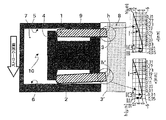
図1:本発明による油かきリングの第1の構成の横断面図である。
図2:本発明による油かきリングの第2の構成の横断面図である。
Embodiments of the present invention will be described below with reference to the drawings.
FIG. 1 is a cross-sectional view of a first configuration of an oiled ring according to the present invention.
FIG. 2 is a cross-sectional view of the second configuration of the oiled ring according to the present invention.
図1から見て取れるように、複数部分から成る油かきリング10は2つのスチールバンド・ディスク(サイドレール)1,2と1つの拡開ばね(エキスパンダ)4とから成っている。拡開ばね4はディスクを、軸方向ではピストンに設けられたリング溝7のその都度1つの側面(フランク)5,6に押し付け、半径方向ではシリンダ壁8に押し付ける。リング溝側面5はピストントップ側の面であり、リング溝側面6はピストントップとは反対側の面である。本発明によりディスク1は、ディスクの周面にわたって延在する頂点線3を備えた、凸曲面状に非対称に成形された走行面hを有しており、ディスク2は、頂点線3′を備えた凸曲面状の非対称の走行面h′を有している。その際、それぞれの頂点線3,3′は、シリンダ壁8と接触するエッジとして、油かきのために役立つ。図1に示した第1の実施例で、ディスク1,2はピストンに組み付けられた状態で、その頂点線3,3′(エッジ)がそれぞれリング溝7の中央に向かって方向付けられているように互いに配置されている。図1に示したこのディスク配置は「逆の向き(gegensinnig)」と理解されるべきであり、これに対して図2に示したディスク配置は「同じ向き(gleichsinnig)」と理解されるべきである。図2に示した実施例では両頂点線3,3′(エッジ)がピストントップ側のリング溝側面5から離反するように拡開ばね4の間に配置されている。
As can be seen from FIG. 1, the
本発明により、ディスクの走行面h,h′は、エンジン運転中の数100時間のならし運転プロセスに相当する形状を有している。この形状は、両ディスク1,2の走行面h,h′が横断面で見て、第1の区分(I)で、h(x)=ax+bx2(ただし、xはデカルト座標系におけるmm単位の走行面座標であり、a,bは係数である。係数aはディスクの軸方向の側面遊びaF(=リング溝の外径に沿って測定した、ディスクとリング溝側面との間の間隔(図1参照))とディスクの幅B(=全幅=ディスクの半径方向幅)との比により定義され、係数bは走行面曲率の値として定義される。)により表される2次の多項式のほぼ非対称の形状に従い、エッジとして構成された支持する頂点(II)h(x=0)の後、第3の区分(III)で、関数h(x)=cx2(ただし、cはbの倍数として定義される。)のほぼ非対称の形状に従うことにより特徴付けられている。例えば0.4mmの厚さを有するディスクでは、値h(x)=35x+50x2である。それにより、図1および図2に応じて示した、mm単位の走行面座標xとμm単位のふくらみh(x)とを有する横断面曲線が得られる。この多項式の係数が固有の応用事例に合わせて調整され得ることは明らかである。その際、ここでの主要なパラメータはシリンダ直径、ディスク横断面の寸法、拡開ばねに設けられた台架の構成およびリング溝における組み付けられたスチールバンド・油かきリングの軸方向の遊び比である。本発明による走行面h,h′の典型的なふくらみは、背景技術による構成が3〜15μm/0.15mmであるのに対して、約2〜10μm/0.4mmである。
According to the present invention, the running surfaces h and h 'of the disc have a shape corresponding to a running operation process of several hundred hours during engine operation. In this shape, the running surfaces h and h ′ of both
機能的に、本発明により改善された油かき作用は、ディスクの走行面h、h′にシリンダ軸線方向で作用する摩擦力が、ディスクを皿状に反らせるトルクを生ぜしめることにより提供されている。このことが可能であるのは、拡開ばね4の構成がディスク1,2の軸方向での運動をとりわけ内側の台架で阻止し、それに対して、外側の台架で明らかに大きな軸方向の運動振幅が可能であるからである。摩擦力、ひいてはトルクは、ピストンのストローク方向に依存して符号を切り替える。摩擦力の高さがなお速度に依存しているので、このことは皿状の反りの絶え間ない変化を結果として伴い、「ダイナミック・ツイスト(dynamisches Twisten)」と呼ばれる。このダイナミック・ツイストにより、図1に示すように、ストローク方向に応じて一方の溝側面に当て付けられたディスクが、走行面の非対称の傾きと相俟って、良好な油かき作用(エッジ支持:線接触)を生ぜしめるのに対し、その都度他方のディスクは、走行面の所定のふくらみに基づいて、改善された流体力学(フェース支持:面接触)を有している。それによりこのディスクにおける摩擦は減じられる。このディスクはツイストされた状態でそれに加えてなおより悪い油かき作用を有している。ストローク方向の変化は、両ディスクの、その都度別の位置への折り返しを生ぜしめる。ただし、説明した関係にはそれにより原理的な変更はない。
Functionally, the improved scouring action according to the invention is provided by the fact that the frictional force acting on the running surfaces h, h 'of the disc in the cylinder axial direction produces a torque that causes the disc to warp in a dish-like shape. . This is possible because the configuration of the spreading
複数部分から成るスチールバンド・油かきリングの組み立て時、リングの正しい位置での方向付けが留意されねばならない。このことは例えば、一方のディスク側面のカラーマークにより保証されることができる。 When assembling a multi-part steel band / oiled ring, the orientation of the ring in the correct position must be noted. This can be ensured, for example, by a color mark on the side of one disk.
走行面形状もしくは走行面輪郭の製作は例えばラッピングにより実施されることができる。 Production of the running surface shape or running surface contour can be carried out, for example, by lapping.
10 油かきリング
1 ディスク
2 ディスク
3 頂点線(エッジ)
3′ 頂点線(エッジ)
4 拡開ばね
5 ピストントップ側のリング溝側面
6 ピストントップとは反対側のリング溝側面
7 リング溝
8 シリンダ壁
9 ピストン
h,h′ 走行面
10
3 'Vertex line (edge)
4 Expanding
Claims (3)
形式のものにおいて、
両ディスク(1,2)の走行面(h,h′)が、ならし運転されたエンジン状態における磨耗に近い最終輪郭に相当するように形成されており、オイルリング(10)がピストンに組み付けられた状態で、走行面(h,h′)の頂点線(3,3′)がそれぞれ逆の向きでリング溝(7)の中央に向かって方向付けられている
ことを特徴とする、内燃機関のピストンのための、複数部分から成る油かきリング。A multi-part oiling ring (10) for a piston of an internal combustion engine is provided with two discs (1, 2) of steel bands having parallel sides, the disc (1 , 2) has an asymmetrical shape of one convex curved surface each time with a vertex line (3, 3 ') extending over the circumference of the disk, Furthermore, an expansion spring (4) arranged between the discs is provided, the expansion spring (4) providing a disc, one in each case of a ring groove (7) provided in the piston in the axial direction. In the type that is pressed against the side surface (5, 6) and pressed against the cylinder wall (8) in the radial direction,
The running surfaces (h, h ') of both discs (1, 2) are formed so as to correspond to the final contour close to wear in the engine state in which the running-in is performed, and the oil ring (10) is assembled to the piston. In the internal state, the vertex lines (3, 3 ') of the running surfaces (h, h') are directed in opposite directions toward the center of the ring groove ( 7 ). A multi-part oiling ring for engine pistons.
形式のものにおいて、
両ディスク(1,2)の走行面(h,h′)が、ならし運転されたエンジン状態における磨耗に近い最終輪郭に相当するように形成されており、オイルリング(10)がピストンに組み付けられた状態で、
ディスクの走行面(h,h′)の頂点線(3,3′)がそれぞれ同じ向きで、リング溝(7)の、ピストントップとは反対側の側面(6)に向かって方向付けられている
ことを特徴とする、内燃機関のピストンのための、複数部分から成る油かきリング。 A multi-part oiling ring (10) for a piston of an internal combustion engine is provided with two discs (1, 2) of steel bands having parallel sides, the disc (1 , 2) has an asymmetrical shape of one convex curved surface each time with a vertex line (3, 3 ') extending over the circumference of the disk, Furthermore, an expansion spring (4) arranged between the discs is provided, the expansion spring (4) providing a disc, one in each case of a ring groove (7) provided in the piston in the axial direction. It is pressed against the side surfaces (5, 6) and in the radial direction it is pressed against the cylinder wall (8).
In the form of
The running surfaces (h, h ') of both discs (1, 2) are formed so as to correspond to the final contour close to wear in the engine state in which the running-in is performed, and the oil ring (10) is assembled to the piston. In the state
The vertex lines (3, 3 ') of the running surfaces (h, h') of the disc are oriented in the same direction and directed toward the side surface (6) of the ring groove (7) opposite to the piston top. Have
A multi-part oil ring for a piston of an internal combustion engine, characterized in that
−第1の区分(I)で、h(x)=ax+bx2により表される2次の多項式の非対称の形状に従い
(ただし、xはデカルト座標系におけるmm単位の走行面座標であり、a,bは係数である。係数aはディスクの軸方向の側面遊び(aF)とディスクの幅(B)との比により定義され、係数bは走行面曲率の値として定義される。)、
−エッジとして構成された支持する頂点(II)h(x=0)の後、
−第3の区分(III)で、関数h(x)=cx2(ただし、cはbの倍数として定義される。)の非対称の形状に従う、
請求項1又は2記載の、複数部分から成る油かきリング。The running surfaces (h, h ') of both disks (1, 2)
-In the first section (I), according to the asymmetric shape of a quadratic polynomial represented by h (x) = ax + bx 2 (where x is the running plane coordinates in mm in the Cartesian coordinate system, a, b is a coefficient, the coefficient a is defined by the ratio of the side play ( aF ) in the axial direction of the disc and the width ( B ) of the disc, and the coefficient b is defined as the value of the curvature of the running surface).
After a supporting vertex (II) h (x = 0) configured as an edge,
In the third section (III), according to the asymmetric shape of the function h (x) = cx 2 (where c is defined as a multiple of b),
The oil scoring ring comprising a plurality of parts according to claim 1 or 2 .
Applications Claiming Priority (3)
| Application Number | Priority Date | Filing Date | Title |
|---|---|---|---|
| DE10340312A DE10340312A1 (en) | 2003-09-02 | 2003-09-02 | Multi-piece oil scraper ring for pistons of internal combustion engines |
| DE10340312.4 | 2003-09-02 | ||
| PCT/DE2004/001939 WO2005024277A1 (en) | 2003-09-02 | 2004-09-01 | Multipart oil wiping ring for pistons of internal combustion engines |
Publications (2)
| Publication Number | Publication Date |
|---|---|
| JP2007504416A JP2007504416A (en) | 2007-03-01 |
| JP4800946B2 true JP4800946B2 (en) | 2011-10-26 |
Family
ID=34258328
Family Applications (1)
| Application Number | Title | Priority Date | Filing Date |
|---|---|---|---|
| JP2006525614A Expired - Fee Related JP4800946B2 (en) | 2003-09-02 | 2004-09-01 | Multi-part oil ring for internal combustion engine pistons |
Country Status (9)
| Country | Link |
|---|---|
| US (1) | US7306232B2 (en) |
| EP (1) | EP1664597B1 (en) |
| JP (1) | JP4800946B2 (en) |
| KR (1) | KR101292934B1 (en) |
| CN (1) | CN100445609C (en) |
| BR (1) | BRPI0414053B1 (en) |
| DE (2) | DE10340312A1 (en) |
| ES (1) | ES2290768T3 (en) |
| WO (1) | WO2005024277A1 (en) |
Cited By (3)
| Publication number | Priority date | Publication date | Assignee | Title |
|---|---|---|---|---|
| KR20160095194A (en) | 2014-09-12 | 2016-08-10 | 티피알 가부시키가이샤 | Combined oil ring |
| KR101898049B1 (en) | 2017-07-05 | 2018-09-12 | 티피알 가부시키가이샤 | Combination oiling |
| WO2019008780A1 (en) | 2017-07-05 | 2019-01-10 | Tpr株式会社 | Combined oil ring |
Families Citing this family (15)
| Publication number | Priority date | Publication date | Assignee | Title |
|---|---|---|---|---|
| DE10340301A1 (en) * | 2003-09-02 | 2005-04-28 | Mahle Gmbh | Multi-piece oil scraper ring for pistons of internal combustion engines |
| DE10340302A1 (en) * | 2003-09-02 | 2005-04-14 | Mahle Gmbh | Oil scraper ring for pistons of internal combustion engines |
| DE10340313A1 (en) * | 2003-09-02 | 2005-05-19 | Mahle Gmbh | Oil scraper ring groove arrangement for pistons of internal combustion engines |
| DE102005023620B4 (en) * | 2005-05-21 | 2010-06-02 | Federal-Mogul Burscheid Gmbh | Process for producing lamellar sealing elements and lamellar sealing element |
| DE102006030348B3 (en) | 2006-06-30 | 2007-11-15 | Federal-Mogul Burscheid Gmbh | Oil wiper comprises a steel band ring with parallel planar front surfaces, a crowned outer peripheral surface and a crowned inner peripheral surface |
| US8403334B2 (en) * | 2009-01-07 | 2013-03-26 | Mahle Engine Components Usa, Inc. | Multi-rail piston ring |
| DE102012000241B4 (en) | 2011-05-10 | 2016-12-08 | Federal-Mogul Burscheid Gmbh | Piston ring for 2-stroke engines |
| WO2015101938A1 (en) * | 2013-12-30 | 2015-07-09 | Mahle International Gmbh | Oil control ring assembly |
| DE112015001071T5 (en) * | 2014-03-01 | 2016-12-08 | Mahle International Gmbh | oil control ring |
| JP6122901B2 (en) * | 2014-07-31 | 2017-04-26 | 日本ピストンリング株式会社 | Combination oil ring |
| JP6222023B2 (en) | 2014-09-12 | 2017-11-01 | マツダ株式会社 | Oil ring |
| JP6530200B2 (en) * | 2015-02-23 | 2019-06-12 | 株式会社リケン | side rail |
| JP6533670B2 (en) * | 2015-03-12 | 2019-06-19 | 株式会社リケン | side rail |
| CN106089483A (en) * | 2016-07-14 | 2016-11-09 | 邹敏 | A kind of novel compositions piston ring |
| US12117085B2 (en) * | 2022-07-19 | 2024-10-15 | Mahle International Gmbh | Piston ring |
Citations (5)
| Publication number | Priority date | Publication date | Assignee | Title |
|---|---|---|---|---|
| JPS57196238U (en) * | 1981-06-08 | 1982-12-13 | ||
| JPS6097345U (en) * | 1983-12-10 | 1985-07-03 | 株式会社リケン | piston ring |
| JPH09144881A (en) * | 1995-11-21 | 1997-06-03 | Teikoku Piston Ring Co Ltd | Combination oil ring |
| US6039321A (en) * | 1997-10-28 | 2000-03-21 | Hyundai Motor Company, Ltd. | Piston ring device for use in a combustion engine of a vehicle |
| JP2000320672A (en) * | 1999-05-12 | 2000-11-24 | Nippon Piston Ring Co Ltd | Narrow width three-piece type combination oil ring |
Family Cites Families (22)
| Publication number | Priority date | Publication date | Assignee | Title |
|---|---|---|---|---|
| US3430968A (en) * | 1966-02-24 | 1969-03-04 | Sealed Power Corp | Piston ring assembly |
| JPS4922964B1 (en) | 1969-12-29 | 1974-06-12 | ||
| US3921988A (en) * | 1971-04-19 | 1975-11-25 | Ramsey Corp Trw Inc | Piston and resilient plastic piston ring combination |
| DE3638728A1 (en) | 1986-01-30 | 1987-08-06 | Thompson Gmbh Trw | MULTI-PIECE OIL SCRAPER FOR COMBUSTION ENGINES |
| BR8802641A (en) * | 1988-05-26 | 1990-01-09 | Cofap | RING SEGMENT FOR INTERNAL COMBUSTION ENGINES |
| US4907545A (en) * | 1988-12-28 | 1990-03-13 | Caterpillar Inc. | Liquid cooled piston ring carrier assembly and piston using same |
| JP2707475B2 (en) * | 1990-07-20 | 1998-01-28 | 日本ピストンリング株式会社 | Thin 3-piece oil ring |
| DE4300531C1 (en) | 1993-01-12 | 1994-02-17 | Daimler Benz Ag | Producing piston rings - with the TOP side marked after production of the asymmetric running face |
| BR9503548A (en) * | 1994-08-08 | 1996-05-28 | Dana Corp | Piston ring assembly for oil control with conical face floating rails |
| DE4429649C2 (en) | 1994-08-20 | 1998-02-19 | Ae Goetze Gmbh | Piston ring |
| JP3437312B2 (en) * | 1995-02-16 | 2003-08-18 | 株式会社リケン | Seal ring and sealing device |
| JP3228116B2 (en) * | 1996-01-29 | 2001-11-12 | 帝国ピストンリング株式会社 | Combination oil ring |
| CN1102210C (en) * | 1997-02-18 | 2003-02-26 | 宇秀明 | Enforced seal oil ring |
| US5921553A (en) * | 1997-09-02 | 1999-07-13 | Klein; Thomas G. | Sealing ring assembly for a single sealing ring piston |
| JP2001082605A (en) * | 1999-09-16 | 2001-03-30 | Nippon Piston Ring Co Ltd | Combination oil ring |
| JP2003148617A (en) * | 2001-11-15 | 2003-05-21 | Nippon Piston Ring Co Ltd | Steel-made combined oil control ring |
| JP4132815B2 (en) * | 2001-12-28 | 2008-08-13 | 株式会社リケン | Side rail and combination oil ring |
| DE60326055D1 (en) * | 2002-10-29 | 2009-03-19 | Toyota Motor Co Ltd | OIL RING |
| JP4322500B2 (en) | 2002-12-18 | 2009-09-02 | 帝国ピストンリング株式会社 | Combination oil ring |
| DE10340313A1 (en) * | 2003-09-02 | 2005-05-19 | Mahle Gmbh | Oil scraper ring groove arrangement for pistons of internal combustion engines |
| DE10340301A1 (en) * | 2003-09-02 | 2005-04-28 | Mahle Gmbh | Multi-piece oil scraper ring for pistons of internal combustion engines |
| TWI255885B (en) * | 2003-10-27 | 2006-06-01 | Riken Kk | Three-piece type combined oil control ring |
-
2003
- 2003-09-02 DE DE10340312A patent/DE10340312A1/en not_active Withdrawn
-
2004
- 2004-09-01 US US10/570,103 patent/US7306232B2/en not_active Expired - Lifetime
- 2004-09-01 CN CNB2004800251292A patent/CN100445609C/en not_active Expired - Fee Related
- 2004-09-01 EP EP04786701A patent/EP1664597B1/en not_active Expired - Lifetime
- 2004-09-01 BR BRPI0414053-2A patent/BRPI0414053B1/en not_active IP Right Cessation
- 2004-09-01 ES ES04786701T patent/ES2290768T3/en not_active Expired - Lifetime
- 2004-09-01 KR KR1020067004190A patent/KR101292934B1/en active IP Right Grant
- 2004-09-01 WO PCT/DE2004/001939 patent/WO2005024277A1/en active IP Right Grant
- 2004-09-01 JP JP2006525614A patent/JP4800946B2/en not_active Expired - Fee Related
- 2004-09-01 DE DE502004004310T patent/DE502004004310D1/en not_active Expired - Lifetime
Patent Citations (5)
| Publication number | Priority date | Publication date | Assignee | Title |
|---|---|---|---|---|
| JPS57196238U (en) * | 1981-06-08 | 1982-12-13 | ||
| JPS6097345U (en) * | 1983-12-10 | 1985-07-03 | 株式会社リケン | piston ring |
| JPH09144881A (en) * | 1995-11-21 | 1997-06-03 | Teikoku Piston Ring Co Ltd | Combination oil ring |
| US6039321A (en) * | 1997-10-28 | 2000-03-21 | Hyundai Motor Company, Ltd. | Piston ring device for use in a combustion engine of a vehicle |
| JP2000320672A (en) * | 1999-05-12 | 2000-11-24 | Nippon Piston Ring Co Ltd | Narrow width three-piece type combination oil ring |
Cited By (5)
| Publication number | Priority date | Publication date | Assignee | Title |
|---|---|---|---|---|
| KR20160095194A (en) | 2014-09-12 | 2016-08-10 | 티피알 가부시키가이샤 | Combined oil ring |
| US9784369B2 (en) | 2014-09-12 | 2017-10-10 | Tpr Co., Ltd. | Combination oil ring |
| KR101898049B1 (en) | 2017-07-05 | 2018-09-12 | 티피알 가부시키가이샤 | Combination oiling |
| WO2019008780A1 (en) | 2017-07-05 | 2019-01-10 | Tpr株式会社 | Combined oil ring |
| US10571024B2 (en) | 2017-07-05 | 2020-02-25 | Tpr Co., Ltd. | Combination oil ring |
Also Published As
| Publication number | Publication date |
|---|---|
| CN100445609C (en) | 2008-12-24 |
| US20060273525A1 (en) | 2006-12-07 |
| EP1664597A1 (en) | 2006-06-07 |
| EP1664597B1 (en) | 2007-07-11 |
| WO2005024277A1 (en) | 2005-03-17 |
| DE10340312A1 (en) | 2005-05-12 |
| CN1846087A (en) | 2006-10-11 |
| JP2007504416A (en) | 2007-03-01 |
| BRPI0414053B1 (en) | 2018-03-13 |
| KR20070020172A (en) | 2007-02-20 |
| ES2290768T3 (en) | 2008-02-16 |
| BRPI0414053A (en) | 2006-10-24 |
| US7306232B2 (en) | 2007-12-11 |
| KR101292934B1 (en) | 2013-08-02 |
| DE502004004310D1 (en) | 2007-08-23 |
Similar Documents
| Publication | Publication Date | Title |
|---|---|---|
| JP4800946B2 (en) | Multi-part oil ring for internal combustion engine pistons | |
| JP4778429B2 (en) | Soil ring-ring groove-assembly for internal combustion engine pistons | |
| WO2007088847A1 (en) | Three-piece oil ring and combination of three-piece oil ring and piston | |
| JP6222023B2 (en) | Oil ring | |
| WO2005078268A1 (en) | Piston device for internal combustion engine | |
| JP5487439B2 (en) | Piston with skirt with oil flow slot | |
| JP7254836B2 (en) | Combined oil ring | |
| WO2019008780A1 (en) | Combined oil ring | |
| KR20060123586A (en) | Piston pin bearing for pistons of an internal combustion engine | |
| JPWO2019008780A1 (en) | Combination oil ring | |
| JP5907955B2 (en) | Oil control ring with iron body for internal combustion engine | |
| JP4705574B2 (en) | Soil ring for internal combustion engine pistons | |
| JP6394773B2 (en) | Oil ring | |
| JP4800945B2 (en) | Soil ring for internal combustion engine pistons | |
| JP2019523370A (en) | One-piece oil control ring | |
| JP4382220B2 (en) | Combination oil ring | |
| JP2003328852A (en) | Piston ring for internal combustion engine | |
| WO2022200465A1 (en) | Oil control ring for internal combustion engines | |
| JP2582093Y2 (en) | Steel oil control ring | |
| JPH0669522U (en) | Steel combination oil control ring | |
| KR20190101089A (en) | Piston ring for engine | |
| JP2001336636A (en) | Spacer expander of combination oil ring |
Legal Events
| Date | Code | Title | Description |
|---|---|---|---|
| A621 | Written request for application examination |
Free format text: JAPANESE INTERMEDIATE CODE: A621 Effective date: 20070613 |
|
| A131 | Notification of reasons for refusal |
Free format text: JAPANESE INTERMEDIATE CODE: A131 Effective date: 20100910 |
|
| A977 | Report on retrieval |
Free format text: JAPANESE INTERMEDIATE CODE: A971007 Effective date: 20100916 |
|
| A601 | Written request for extension of time |
Free format text: JAPANESE INTERMEDIATE CODE: A601 Effective date: 20101210 |
|
| A602 | Written permission of extension of time |
Free format text: JAPANESE INTERMEDIATE CODE: A602 Effective date: 20101222 |
|
| RD04 | Notification of resignation of power of attorney |
Free format text: JAPANESE INTERMEDIATE CODE: A7424 Effective date: 20101228 |
|
| A601 | Written request for extension of time |
Free format text: JAPANESE INTERMEDIATE CODE: A601 Effective date: 20110111 |
|
| A602 | Written permission of extension of time |
Free format text: JAPANESE INTERMEDIATE CODE: A602 Effective date: 20110118 |
|
| A601 | Written request for extension of time |
Free format text: JAPANESE INTERMEDIATE CODE: A601 Effective date: 20110210 |
|
| A602 | Written permission of extension of time |
Free format text: JAPANESE INTERMEDIATE CODE: A602 Effective date: 20110218 |
|
| A521 | Request for written amendment filed |
Free format text: JAPANESE INTERMEDIATE CODE: A523 Effective date: 20110310 |
|
| TRDD | Decision of grant or rejection written | ||
| A01 | Written decision to grant a patent or to grant a registration (utility model) |
Free format text: JAPANESE INTERMEDIATE CODE: A01 Effective date: 20110713 |
|
| A01 | Written decision to grant a patent or to grant a registration (utility model) |
Free format text: JAPANESE INTERMEDIATE CODE: A01 |
|
| A61 | First payment of annual fees (during grant procedure) |
Free format text: JAPANESE INTERMEDIATE CODE: A61 Effective date: 20110804 |
|
| FPAY | Renewal fee payment (event date is renewal date of database) |
Free format text: PAYMENT UNTIL: 20140812 Year of fee payment: 3 |
|
| R150 | Certificate of patent or registration of utility model |
Free format text: JAPANESE INTERMEDIATE CODE: R150 Ref document number: 4800946 Country of ref document: JP Free format text: JAPANESE INTERMEDIATE CODE: R150 |
|
| R250 | Receipt of annual fees |
Free format text: JAPANESE INTERMEDIATE CODE: R250 |
|
| R250 | Receipt of annual fees |
Free format text: JAPANESE INTERMEDIATE CODE: R250 |
|
| R250 | Receipt of annual fees |
Free format text: JAPANESE INTERMEDIATE CODE: R250 |
|
| R250 | Receipt of annual fees |
Free format text: JAPANESE INTERMEDIATE CODE: R250 |
|
| R250 | Receipt of annual fees |
Free format text: JAPANESE INTERMEDIATE CODE: R250 |
|
| R250 | Receipt of annual fees |
Free format text: JAPANESE INTERMEDIATE CODE: R250 |
|
| R250 | Receipt of annual fees |
Free format text: JAPANESE INTERMEDIATE CODE: R250 |
|
| LAPS | Cancellation because of no payment of annual fees |