JP4800545B2 - Liquid filter, especially oil filter - Google Patents
Liquid filter, especially oil filter Download PDFInfo
- Publication number
- JP4800545B2 JP4800545B2 JP2001567909A JP2001567909A JP4800545B2 JP 4800545 B2 JP4800545 B2 JP 4800545B2 JP 2001567909 A JP2001567909 A JP 2001567909A JP 2001567909 A JP2001567909 A JP 2001567909A JP 4800545 B2 JP4800545 B2 JP 4800545B2
- Authority
- JP
- Japan
- Prior art keywords
- filter
- chamber
- flange
- liquid
- casing
- Prior art date
- Legal status (The legal status is an assumption and is not a legal conclusion. Google has not performed a legal analysis and makes no representation as to the accuracy of the status listed.)
- Expired - Lifetime
Links
- 239000007788 liquid Substances 0.000 title claims description 75
- 230000008878 coupling Effects 0.000 claims description 12
- 238000010168 coupling process Methods 0.000 claims description 12
- 238000005859 coupling reaction Methods 0.000 claims description 12
- 230000001105 regulatory effect Effects 0.000 claims description 11
- 229910052751 metal Inorganic materials 0.000 claims description 10
- 239000002184 metal Substances 0.000 claims description 10
- 238000007789 sealing Methods 0.000 claims description 9
- 238000005192 partition Methods 0.000 claims description 6
- 239000003921 oil Substances 0.000 description 10
- 238000002485 combustion reaction Methods 0.000 description 6
- 239000010687 lubricating oil Substances 0.000 description 4
- 238000012805 post-processing Methods 0.000 description 4
- 238000002788 crimping Methods 0.000 description 3
- 238000005520 cutting process Methods 0.000 description 3
- 238000004512 die casting Methods 0.000 description 3
- 238000003780 insertion Methods 0.000 description 3
- 230000037431 insertion Effects 0.000 description 3
- 229910052782 aluminium Inorganic materials 0.000 description 2
- XAGFODPZIPBFFR-UHFFFAOYSA-N aluminium Chemical compound [Al] XAGFODPZIPBFFR-UHFFFAOYSA-N 0.000 description 2
- 238000005266 casting Methods 0.000 description 2
- 238000004519 manufacturing process Methods 0.000 description 2
- 238000000034 method Methods 0.000 description 2
- 238000000465 moulding Methods 0.000 description 2
- 229910000639 Spring steel Inorganic materials 0.000 description 1
- 239000000470 constituent Substances 0.000 description 1
- 230000001419 dependent effect Effects 0.000 description 1
- 238000007599 discharging Methods 0.000 description 1
- 239000012530 fluid Substances 0.000 description 1
- 238000009434 installation Methods 0.000 description 1
- 239000000463 material Substances 0.000 description 1
- 238000005058 metal casting Methods 0.000 description 1
- 230000036316 preload Effects 0.000 description 1
- 238000000926 separation method Methods 0.000 description 1
Images


Classifications
-
- F—MECHANICAL ENGINEERING; LIGHTING; HEATING; WEAPONS; BLASTING
- F01—MACHINES OR ENGINES IN GENERAL; ENGINE PLANTS IN GENERAL; STEAM ENGINES
- F01M—LUBRICATING OF MACHINES OR ENGINES IN GENERAL; LUBRICATING INTERNAL COMBUSTION ENGINES; CRANKCASE VENTILATING
- F01M11/00—Component parts, details or accessories, not provided for in, or of interest apart from, groups F01M1/00 - F01M9/00
- F01M11/03—Mounting or connecting of lubricant purifying means relative to the machine or engine; Details of lubricant purifying means
- F01M2011/031—Mounting or connecting of lubricant purifying means relative to the machine or engine; Details of lubricant purifying means characterised by mounting means
- F01M2011/033—Mounting or connecting of lubricant purifying means relative to the machine or engine; Details of lubricant purifying means characterised by mounting means comprising coolers or heat exchangers
Landscapes
- Engineering & Computer Science (AREA)
- Mechanical Engineering (AREA)
- General Engineering & Computer Science (AREA)
- Lubrication Details And Ventilation Of Internal Combustion Engines (AREA)
- Filtration Of Liquid (AREA)
Description
【0001】
本発明は、請求項1の上位概念部に記載した特徴を有する、液体フィルタ、特に自動車の内燃機関の潤滑油を浄化するためのオイルフィルタに関する。
このような液体フィルタはEP0816645A1号明細書によって公知であり、内部にリングフィルタインサートを有している。このリングフィルタインサートは液体フィルタにてクリーン側をアンクリーン側から分離している。さらに液体フィルタは金属製のフィルタケーシングを有し、このフィルタケーシングはフランジを有し、このフランジで液体フィルタはねじ結合で構成部分、例えば内燃機関のエンジンブロックにねじ結合される。この場合には前記構成部分は未処理用の液体のための供給通路と処理済みの液体のための排出通路と相対的に無圧のアイドルダクトとを有している。フランジは軸方向に有効なアウタシールを有し、このアウタシールは供給通路と排出通路とアイドルダクトとを取囲んでいる。フランジには供給通路に向かって開いた供給室、排出通路に向かって開いた排出室とアイドルダクトに向かって開いたアイドルダクト室とが構成されている。この場合、個々の室は軸方向に作用するインナシールによって互いにシールされている。フランジが前記構成部分にねじ結合されるねじ結合装置は、軸方向に作用しかつ軸方向に作用するシール、すなわちアウタシールとインナシールを軸方向で前記構成部分に圧着する。
DE4242997C1号明細書にはフィルタケーシングがシールプレートを介してエンジンブロックにフランジ結合されているオイルフィルタが開示されている。これに相応してこのシールプレートはフィルタケーシングのフランジとエンジンブロックとの間に配置されている。フィルタケーシングとは反対側ではさらに、シールプレートに熱交換器が取付けられていることができる。この熱交換器はシールプレートがエンジンブロックに配置されている場合に、エンジンブロックに構成された適当な受容室内へ突入する。
さらにEP0750099A2号明細書及びDE19741449A1号明細書によれば内燃機関のエンジンブロックにケーシングがフランジでねじ結合可能な液体フィルタが開示されている。
【0002】
WO99/39802明細書によれば、プラスチックから成るフィルタケーシングに受容されたリングフィルタインサートと未処理液を供給する供給通路と処理済み液を排出する戻し通路とを有する液体フィルタが公知である。供給通路と戻し通路はフィルタケーシングの受け室内に配置され、この受け室は供給通路と戻し通路とを半径方向で取囲む、フィルタケーシングと一体に構成された安全壁によって制限されている。フィルタケーシングは、未処理のオイルの供給部と処理済みのオイルの排出部とを有する構成部分に密に固定されなければならない。通常はフィルタケーシングは内燃機関のエンジンブロックに固定される。しかし当該構成部分にプラスチックから成るフィルタケーシングを緊密に固定する場合には問題が発生する。何故ならば供給部と排出部とにおいては比較的に高い圧力が発生しているからである。特別な組込み条件に基づき時によっては、フィルタケーシングを軸方向に作用するシールでエンジンブロックに対しシールすることが必要である。プラスチックから成るフィルタケーシングの場合にはこのためにフィルタケーシングをエンジンブロックに対し緊締するのに必要な圧着力がプラスチックケーシングへ導入されることができないという欠点が生じる。
【0003】
DE3903675C2号明細書によれば、フィルタケーシングが上位区分に、リングフィルタインサートを配置するためのフィルタ受容室を有しかつ下位区分に未処理のオイルの流入通路と処理済みオイルの流出通路とを有するオイルフィルタが公知である。内部に統合された通路を有するフィルタケーシングは通常は金属から成るダイカスト鋳造構成部分として製作される。この形式で軸方向で作用するシールにて十分なシール作用を達成するために、必要なプレロード力と圧着力とが金属ケーシング内へ導入することができる。しかし、このように製作されたダイカスト鋳造ケーシングの内部に、例えば内部の通路のために、シールのための平滑な面を構成するためには、ダイカスト鋳造構成部分の入念な後加工が必要である。金属ケーシングの切削加工に際しては多孔質性と巣とに基づき窩穴が生じる。この窩穴自体は構成部分の費用のかかる仕上げ加工を必要とする。
【0004】
本発明の課題は冒頭に述べた形式の液体フィルタのために、軸方向で作用するシールの使用を可能にする構成形態を提供し、その際、比較的に安価に製作可能であるようにすることである。
【0005】
この課題は本発明によれば請求項1の特徴によって解決された。
【0006】
本発明は、従来のフィルタケーシングでは該フィルタケーシングと一体に製造されかつその機能を発揮するために後加工されなければならないフィルタケーシングの構成部分の少なくとも1部分を、別個に製作可能な機能保持体インサートに纏め、フィルタケーシングを緊密に固定しようとする構成部分に対する軸方向のシールをフィルタケーシングと当該構成部分とのねじ結合で実現するという全般的な思想に基づいている。この形式で一方ではこの機能エレメントの特別な後処理の可能が得られ、他方では機能保持体インサートを後加工が不要になるように製作することもできるようになった。例えば機能保持体インサートはプラスチックから、特に注型成形法で製作されている。その際に得られた表面質は十分に高いので後加工は通常は省略することができる。そのうえ、金属から成るフィルタケーシングは軸方向のシールのために十分な軸方向の圧着力を生ぜしめる十分な軸方向の緊締力をもたらすのに十分である強度を有している。全体として特に適価格で製作可能な液体フィルタが得られる。
【0007】
本発明による装置の別の重要な特徴と利点とについては従属請求項、図面及びそれに関連した記述を参照されたい。
【0008】
もちろん、先に述べかつ後からさらに詳しく述べた特徴はそれぞれ記述した組み合わせだけではなく、本発明の枠を逸脱することなしに他の組合わせ又は単独に用いることができることは言うまでもない。
【0009】
以下、本発明の有利な実施例を図面に示し、これについて詳しく説明する。
【0010】
実施例
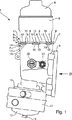
図1に示されているように、ここでは自動車の内燃機関の潤滑油を浄化するためのオイルフィルタとして構成された液体フィルタ1は、フィルタケーシング2を有している。フィルタケーシング2は金属、特に軽金属から、例えばアルミ鋳造体又はアルミダイカスト体として構成されている。図1で見てフィルタケーシング2の右側では、フィルタケーシング2に第1のフランジ3が形成され、この第1のフランジ3で液体フィルタ1は図示されていない構成部分、例えば自動車のエンジンブロックにねじで結合可能である。フィルタケーシング2は上側に第2のフランジ4を有し、この第2のフランジ4でフィルタ室付加部5がフィルタケーシング2に固定されている。このフィルタ室付加部5はフィルタケーシング2とは反対側の上面にてカバー6で閉鎖されている。フィルタ室付加部5内にはここでは図示されていないリングフィルタインサートが配置されている。このリングフィルタインサートは液体フィルタ内でクリーン側をアンクリーン側から分離している。ここではフィルタ室付加部5はプラスチックから、例えば注型成形構成部分として製作されている。同様にカバー6もプラスチックから製作されていることができる。
【0011】
フィルタケーシング2におけるフィルタ室付加部5の固定は特別な形式で行われる。つまり、第2のフランジ4は−フィルタ室付加部5同様−ほぼ円筒形に構成され、フィルタケーシング2から軸方向に突出する円筒壁7を有している。この円筒壁7には軸方向に突出する突起8が構成されている。この突起8は軸方向の自由端に半径方向外方へ突出する隆起部9を有している。図1ではこの隆起部9は、両方の中間の突起8においては、図1の観察者に向かってフィルタケーシング2から突出している。隣り合った突起8の間にはすき間10がある。
【0012】
第2のフランジ4と協働するフィルタ室付加部5の円筒状の区分11には軸方向に突出する突起12が構成されている。この突起12はそれぞれ、フィルタケーシング2の突起8の間の前記すき間10に係合する。フィルタ室付加部5の突起12はフィルタケーシング2に向いた側、図1にて下側に、半径方向外方へ突出する隆起部13を有している。
【0013】
さらにリング状の緊締部材14が設けられ、この緊締部材14は突起8,12の領域で第2のフランジ4を取囲んでいる。この結果、フィルタケーシング2の突起8の隆起部9は緊締部材14を上から半径方向に掴むのに対し、フィルタ室付加部5の突起12の隆起部13は緊締部材14を下から半径方向に掴む。このような形式でフィルタケーシング2に対するフィルタ室付加部5の有効な固定と確保とが得られる。
【0014】
本実施例ではフィルタ室付加部5の突起12にそれぞれ1つの付加的な隆起部15が構成されている。この隆起部15は同様に半径方向で外方へ突起12から突出し、その際に、フィルタケーシング2の突起8の隆起部8のレベルに配置されている。この形式で第2のフランジ4に対する緊締部材14の付加的な固定が得られる。緊締部材14は例えば開いたばね鋼リングから成っている。
【0015】
フィルタケーシング2はその下側に第3のフランジ16を有している。この第3のフランジ16を介し、熱交換器17又は冷却器がフィルタケーシング2へ接続されている。図示の実施例ではこの熱交換器17はいわゆるDonut-Typであり、図示されていない中央の貫通開口を有し、中央の固定ねじ18を介しフィルタケーシング2にねじ結合される。この場合、カバー19は熱交換器17の中央開口を緊密に閉鎖している。
【0016】
さらにフィルタケーシング2は図面観察者に向いた側に第1のセンサ20、例えば温度センサ並びに第2のセンサ、例えば圧力センサを備えている。このためにはフィルタケーシング2に適当なセンサ接続部が構成されている。
【0017】
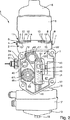
図2に相応して、第1のフランジ3の内部には保持体受容室22が構成されている。この保持体受容室22内には図3に示されているように機能保持体インサート23が配置可能である。第1のフランジ3は軸方向に作用するアウタシール24を備え、該アウタシール24は保持体受容室22,ひいては該保持体受容室22内へ配置された機能保持体インサート23を包囲している。
【0018】
機能保持体インサート23は供給室25を有し、該供給室25は未処理液体用の供給通路に連通している。供給通路は液体フィルタが固定された図示されていない構成部分に配置されている。さらに機能保持体インサート23は排出室26を有している。該排出室26は、液体フィルタ1が固定される前記構成部分に設けられた、処理済みの液体のための排出通路と連通している。さらに機能保持体インサート23は前記構成部分のアイドルダクトと連通するアイドルダクト室27を有している。このようなアイドルダクトは内燃機関のエンジンブロックによって前記構成部分が形成されている場合に規則的にオイルパンに向かって潤滑油を流し、これによりアイドルダクトが比較的に無圧になる。
【0019】
前記各室25,26,27は軸方向に作用するインナシール28によって互いにシールされている。この場合、シール28と24は個別の部材として構成されていることができるが、アウタシール24とインナシール28とが一体のシール体によって形成されている実施例が有利である。第1のフランジ3を前記構成部分もしくはエンジンブロックにねじで固定することによってシール24と28は軸方向で当該構成部分に圧着させられる。このためには機能保持体インサート23が内部で第1のフランジ3もしくはフィルタケーシング2に支えられるように、該機能保持体インサート23が保持体受容室22に適合させられていることは明らかである。この場合には機能保持体インサート23はプラスチックから、例えば注型成形構成部分として製造される。
【0020】
十分なシール作用を達成するために必要な緊締力はフランジ3に対するねじ結合で達成される。これはここではフィルタケーシング2が金属から製作されているために問題なく行うことができる。
【0021】
第1のフランジ3には、アウタシール24を配置するために、閉じられて循環する受容溝29が構成され、この受容溝29にアウタシール24が設置される。図5に相応して前記受容溝29を形成するためには有利な1実施例では、第1のフランジ3の1つの壁30に、機能保持体インサート23に向かって開いた、横断面L字形の、環状の内段31が構成されている。さらに機能保持体インサート23の対向した壁32には第1のフランジ3に向かって開いた、横断面がL字形(鏡像対称的)の環状の外段33が構成されている。機能保持体インサート23の外段33と第1のフランジ3の内段31とは保持体受容室22内へ機能保持体インサート23が挿入された場合に、アウタシール24を受容する受容溝29を形成する。この比較的に費用のかかる構成形態はフィルタケーシング2の製作の有利な簡易化を可能にする。何故ならばフランジ3だけに溝29を配置する場合に生じる、金属鋳造法の枠内では比較的に費用をかけなければ実現できない精密構造が減少させられるからである。シール24は溝29内に、機能保持体インサート23とフランジ3との間に構成された切断個所34もシールされるように配置されている。壁32の寸法は有利には、壁32が軸方向で壁30の上へ突出するように選択されていることができる。この構造形式は前記構成部分に第1のフランジ3をねじ結合する場合に機能保持体インサートに軸方向のプレロードをかけるかまたは機能保持体インサートを軸方向で緊締する。
【0022】
図3に示されているようにインナシール28を受容するためにもそれぞれ1つの溝35が設けられている。この溝35もしくはこれらの溝35はそれぞれ、機能保持体インサート23における個々の室25,29,27を相互に分離する仕切り壁6の、前記構成部分に向いた端部に構成されている。有利な実施例では、この仕切り壁6は図6に示したように2重壁として構成されている。この2重壁は互いにほぼ平行に延びる単壁37を有し、該単壁37は自由端部にて横ウエブ38によって互いに結合されている。横ウエブ38の、前記構成部分に向いた前面側にはインナシール28を受容するための溝35が構成されている。このような形式で構成された仕切り壁6の領域36では第1のフランジ3もしくはフィルタケーシング2にて、前記構成部分に向かって第1のフランジ3から突出するリブ39が構成、特に一体成形されており、該リブ39は2重壁内へ、つまり単壁37の間へ係合し、横ウエブ38を、前記構成部分とは反対の背面側で支持している。このような形式でインナシール28の上に強いプレロードをかけることができる。この場合には同時に機能保持体インサート23のプラスチックの据え込み現象が減少させられる。
【0023】
図3に相応して機能保持体インサート23は、排出開口40を有している。該排出開口40は液体フィルタ1の内部におけるクリーン側と連通する。この場合には図2によればクリーン側の排出接続管部42がフィルタケーシング2の内部へ突入している。この排出接続管部42はフィルタ室付加部5に構成されている。さらに排出室26は別の開口41を有し、この開口41はフィルタケーシング2内に構成された補助通路43と連通している。その補助通路43自体はセンサ20,21のセンサ接続部と接続されている。
【0024】
機能保持体インサート23の供給室25は供給開口44(図3を参照)を介し、フィルタケーシング2の内部に構成された供給通路45(図2参照)と連通している。
【0025】
機能保持体インサート23のアイドルダクト室27は図3によれば、切欠かれて構成されかつ複数の開口46を有している。これらの開口46を介してアイドルダクト室27はフィルタケーシング2によって包囲されたフィルタケーシング2の内室47と接続されている。
【0026】
フィルタケーシング2の内室47に面した側にて機能保持体インサート23には圧力調整弁48が配置されている。この圧力調整弁48の位置は、機能保持体インサート23なしで図2に示されている。この圧力調整弁48は主として、少なくとも1つの半径方向の開口50を有する円筒形のスリーブ49から成っている。スリーブ49の内部には制御ピストン51(図2参照)が軸方向に調節可能に支承されている。この制御ピストン51はばね52でスリーブ49の内部に構成されたピストン座53に対しプレロードがかけられている。ばね52はこの場合には一端で制御ピストン51に支えられかつ他端で、スリーブ49内にて例えば縁曲げ部によって保持された支持円板55に支えられている。ピストン座53を有する軸方向の端部にスリーブ49は軸方向の開口54を有している。
【0027】
組立てられた状態で圧力調整弁48は機能保持体インサート23に保持されている。このためには図4に示したように機能保持体インサート23は背面側に保持部材56を有し、この保持部材56がスリーブを少なくとも部分的にその外側にて掴んでいる。スリーブ49の、開口54を有する端部はシール57を介し、機能保持体インサート23に構成された対応するシール面に支えられている。スリーブ49の反対側の端部は組み立てられた状態で、フィルタケーシング2の内部にてフィルタケーシング2における対応する座58に支えられている。
【0028】
軸方向の開口54は排出室26と連通しているにの対し、制御ピストン51によって制御された半径方向の開口50はアイドルダクト室27及び/又はフィルタケーシング2の内室47と連通している。内室47とアイドルダクト室27とは開口46を介し互いに連通しており、これらの室47,27にはアイドルダクトの圧力、すなわち通常はほぼ大気圧である周辺圧力が作用している。これとは異なって、排出室26には高められた圧力、すなわちここでは図示されていないポンプ、例えば潤滑油回路の油ポンプの吐出圧が作用している。圧力調整弁48は、制御ピストン51が半径方向の開口50を上方の限界圧(調整圧)から開放し、適当な減圧がアイドルダクト室27もしくは内室47を介して行うことができるように調節されている。排出室26における圧力調整弁48の前記配置は、前記構成部分に供給された液体圧が調整され、これにより、誤った液体圧による当該構成部分の損傷の危険が減じられるという利点をもたらす。
【0029】
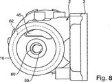
図7に相応してフィルタケーシング2の内部には熱交換器17の低温側に連通した円筒形の接続管部59が形成されている。この接続管部59の内部には片側で開いた座60が構成されている。この座60には個別化可能な構成部材として構成された円板が支持可能である。この円板は図9にて符号61で示されており、熱交換器17の中央のねじ18の外ねじ山と協働する内ねじ山を有している。このような形式でフィルタケーシング2にねじ山を構成する必要なく熱交換器17をフィルタケーシング2にねじ結合することができる。
【0030】
図8に示されているように第3のフランジ16もほぼ円筒状又は円形状に構成され、軸方向に作用する適当なシール62によって熱交換器17に対しシールされている。図面においては前記シール62は単に破断線で示されている。このシール62は供給通路45の第3のフランジ16の中心に対し半径方向外側に配置された、第3のフランジ16に配属された端部を取囲んでいる。この供給通路45はこれに応じて半径方向外に配置された、熱交換器17の図示されていない入口、すなわち熱交換器の高温側に連通する。第3のフランジ16の中心に対しては接続管部59の、第3のフランジ16に配属された端部が配置されている。この端部はそこでは同様に図示されていない熱交換器17の出口と、つまり熱交換器17の低温側に連通している。第3のフランジ16に対し同心的に、別の構成では案内部材、例えばリブがフィルタケーシング2に構成されていることができる。この案内部材は熱交換器17を取付ける際に該熱交換器17と協働しかつ該熱交換器17を第3のフランジ16に対して相対的にセンタリングする。
【0031】
図9に相応してフィルタ室付加部5は、カバー6とは反対側の下面側から軸方向に突出する円筒状の供給接続管部63が構成されている。この供給接続管部59は図7に示されたフィルタケーシング2の接続管部59と差込み継手の形式で協働する。供給接続管部63には半径方向に作用するシール64が取付けられており、このシール64で前記差込み継手がシールされる。供給接続管部63に隣接してフィルタ室付加部5の下側には、排出接続管部42が構成されている。この排出接続管部42はほぼ半径方向にフィルタ室付加部5から突出する(図2参照)。この排出接続管部42は、排出室26に配属された、機能保持体インサート23の裏面側に構成された接続管部65と差込み継手の形式で協働する。この場合にも適当な、半径方向に作用するシール手段が設けられることは明らかである。排出室26の接続管部65は排出開口40を介し排出室26に開口している(図3参照)。
【0032】
機能保持体インサート23にはさらに、その裏面側に、供給室25に配属された接続管部66が配置されている。この接続管部66は同様に円筒形に構成されかつ排出室26の接続管部65に対し平行に延在している。この接続管部66は差込み継手の形式で、フィルタケーシング2の内部に構成された供給通路45の一端構成された接続管部67と協働する。この接続管部66も半径方向に作用するシール68を保持している。接続管部66内には逆流遮断弁69が配置され、この逆流遮断弁69は接続管部66の流過を接続管部67だけに可能にし、逆流は遮断される。接続管部66は供給開口44を介し供給室25へ開口する。
【0033】
機能保持体インサート23の裏面側には、同様に排出室26に配属されて、補助接続管部70が構成されている。この補助接続管部は他の接続管部65,66に対し平行に延び、円筒形に構成されている。この補助接続管部70も半径方向のシール71を有し、差込み継手の形式で、補助通路43の端部に構成された補助接続管部72と協働する。補助接続管部70は開口41を介して排出室26へ開口する。
【0034】
接続管部65,66,70とが平行に構成されかつそれらが差込み継手エレメントとして構成されていることにより、機能保持体インサート23のためには特に簡単な組立の可能性が得られる。
【0035】
この場合、液体フィルタ1の液体の流過は以下の通りである。
【0036】
前記構成部分の供給部からは加熱された、汚染した液体が供給室25へ流入する(図3)。供給室25から液体は接続管部66(図9)を介して供給通路45へ流入する(図2)。供給通路45(図8)から液体は熱交換器17の高温側へ流入する。熱交換器17においては汚染した未処理側の液体の冷却が行われる。熱交換器17の中央からの流出により冷却された液体は、接続管部59(図8)を通ってフィルタ室付加部5の供給接続管部63(図9)へ流入する。フィルタ室付加部5の内部で、汚染した液体はフィルタインサートを貫流し、フィルタケーシング1のクリーン側に達する。いまや冷却されかつ処理された液体は排出接続管部42(図9)を通って排出室26(図3)に達し、そこから前記構成部分の排出部に達する。排出室26を介し、冷却され、処理された液体は補助通路43にも達するので、センサ20と21とを介して、例えば液体温度と液体圧とが検出される。
【0037】
したがって、液体案内はフィルタケーシング2の内室47に対しては常にシールされて行われる。フィルタケーシング2の内部に漏れが発生した場合には、アンクリーン側又はクリーン側の液体は常に、比較的に圧力の低い内室47へ逃げることになる。この内室47は開口46を介しアイドルダクト室27,ひいては当該構成部分のアイドルダクトに連通している。
【0038】
これにより特に簡単に、内室47に開口するアイドルダクト開口をフィルタ室付加部5に設け、このアイドルダクト開口がリングフィルタインサートを取出すために開放されるようにすることができる。
【0039】
本発明による液体フィルタ1の構成は、軸方向にシールされなければならない結合部にて金属部分の間のねじ結合が可能であるように選択されている。このような形式でプラスチック構成部分にはこの材料によって問題なく吸収される負荷しかかからなくなる。フィルタ室付加部5を固定するために行われるフィルタケーシング2による第2のフランジ4を用いた取付けは大きな力を吸収する必要はない。何故ならばフィルタケーシング2の内室47は無圧でありかつ供給接続管部63と接続管部59との間の差込み結合領域においては比較的にわずかな、軸方向に作用する力しかフィルタ室付加部5に作用しないからである。
【図面の簡単な説明】
【図1】 本発明の液体フィルタを組み立てられた状態で示した側面図。
【図2】 図1の液体フィルタを機能保持体インサートなしで図1の矢印IIの方向から見た図。
【図3】 機能保持体と一緒に液体フィルタを示した図2に相当する図。
【図4】 図3の機能保持体インサートを背面側から見た図。
【図5】 図3の設断線Vに沿った詳細断面図。
【図6】 図3の設断線に沿った詳細断面図。
【図7】 図1の液体フィルタのフィルタケーシングを上から見た図。
【図8】 図7のフィルタケーシングを下から見た図。
【図9】 図7のフィルタケーシングなしで液体フィルタを示した図1に相当する側面図。
【符号の説明】
1 液体フィルタ、 2 フィルタケーシング、 3 フランジ、 4 フランジ、 5 フィルタ室付加部、 6 カバー、 7 円筒壁、 8 突起、 9 隆起部、 10 すき間、 11 円筒区分、 12 突起、 13 隆起部、 14 緊締部材、 15 隆起部、 16 フランジ、 17 熱交換器、 18 固定ねじ、 19 カバー、 20,21 センサ、 22 保持体受容室、 23 機能保持体インサート、 24 アウタシール、 25 供給室、 26 排出室、 27 アイドルダクト室、28 インナシール、 29 受容溝、 30 壁、 31 内段、 32 壁、 33 外段、 34 切断部、 35 溝、 36 分離壁、 37 単個壁、 38 横ウエブ、 39 リブ、 40 排出開口、 41 開口、 42 排出接続部、 43 補助通路、 44 供給開口、 45 供給通路、 46 開口、 47 内室、 48 圧力調整弁、 49 スリーブ、 50 開口、 51 制御ピストン、 52 ばね、 53 ピストン座、 54 開口、 55 支持円板、 56 保持部材、 57 シール、 59 接続管部、 60 座、 61 円板、 62 シール、 63 供給接続部、 64 シール、 65 接続管部、 66 結合管部、 67 接続管部、 68 シール、 69 逆流遮断弁、 70 補助結合管部、 71 シール、 72 補助接続管部[0001]
The present invention relates to a liquid filter, particularly an oil filter for purifying lubricating oil of an internal combustion engine of an automobile, having the characteristics described in the superordinate conceptual part of
Such a liquid filter is known from EP 0816645 A1 and has a ring filter insert inside. In this ring filter insert, the clean side is separated from the unclean side by a liquid filter. Furthermore, the liquid filter has a metal filter casing, which has a flange, in which the liquid filter is screwed to a component part, for example an engine block of an internal combustion engine, with a screw connection. In this case, the component has a supply passage for untreated liquid, a discharge passage for treated liquid and a relatively non-pressure idle duct. The flange has an axially effective outer seal which surrounds the supply passage, the discharge passage and the idle duct. The flange includes a supply chamber that opens toward the supply passage, a discharge chamber that opens toward the discharge passage, and an idle duct chamber that opens toward the idle duct. In this case, the individual chambers are sealed together by an inner seal acting in the axial direction. A screw coupling device in which a flange is screwed to the component part acts in the axial direction and presses the axially acting seal, that is, an outer seal and an inner seal, against the component part in the axial direction.
DE 4242997 C1 discloses an oil filter in which a filter casing is flanged to the engine block via a seal plate. Correspondingly, this sealing plate is arranged between the filter casing flange and the engine block. A heat exchanger can also be attached to the sealing plate on the side opposite to the filter casing. The heat exchanger enters a suitable receiving chamber configured in the engine block when the seal plate is disposed in the engine block.
Furthermore, according to EP 0 705 999 A2 and DE 197 14 449 A1, a liquid filter is disclosed in which the casing can be screwed to the engine block of the internal combustion engine with a flange.
[0002]
According to WO 99/39802, a liquid filter having a ring filter insert received in a filter casing made of plastic, a supply passage for supplying untreated liquid, and a return passage for discharging treated liquid is known. The supply passage and the return passage are arranged in a receiving chamber of the filter casing, the receiving chamber being limited by a safety wall that is integrated with the filter casing and surrounds the supply passage and the return passage in the radial direction. The filter casing must be tightly secured to a component having an untreated oil supply and a treated oil discharge. Usually, the filter casing is fixed to the engine block of the internal combustion engine. However, problems arise when the filter casing made of plastic is tightly fixed to the component. This is because relatively high pressure is generated in the supply section and the discharge section. Depending on the particular installation conditions, it is sometimes necessary to seal the filter casing against the engine block with an axially acting seal. In the case of a filter casing made of plastic, this has the disadvantage that the crimping force required to tighten the filter casing against the engine block cannot be introduced into the plastic casing.
[0003]
According to DE 3903675C2, the filter casing has a filter receiving chamber for placing the ring filter insert in the upper section and an untreated oil inflow passage and a treated oil outflow passage in the lower section. Oil filters are known. Filter casings with passages integrated therein are usually manufactured as die cast components made of metal. In order to achieve a sufficient sealing action with a seal acting in this manner in the axial direction, the necessary preloading and crimping forces can be introduced into the metal casing. However, in order to construct a smooth surface for the seal inside the die-casting casing thus produced, for example for the internal passage, careful post-processing of the die-casting components is necessary. . When cutting the metal casing, a cavity is formed based on the porosity and the nest. This cavity itself requires expensive finishing of the components.
[0004]
The object of the present invention is to provide a configuration which allows the use of an axially acting seal for a liquid filter of the type mentioned at the outset, so that it can be produced relatively inexpensively. That is.
[0005]
This problem has been solved according to the invention by the features of
[0006]
In the conventional filter casing, the function holder capable of separately manufacturing at least one of the constituent parts of the filter casing that is manufactured integrally with the filter casing and must be post-processed to perform its function. It is based on the general idea that the seal in the axial direction with respect to the components to be tightly fixed to the filter casing is realized by screw connection between the filter casing and the components. In this way, on the one hand, special post-processing of this functional element is possible, and on the other hand, it is also possible to produce the functional support insert so that no post-processing is necessary. For example, the functional support insert is made of plastic, in particular by a casting method. Since the surface quality obtained at this time is sufficiently high, post-processing can usually be omitted. Moreover, the metal filter casing has sufficient strength to provide sufficient axial clamping force to produce sufficient axial crimping force for axial sealing. As a whole, a liquid filter that can be manufactured at a particularly reasonable price is obtained.
[0007]
For further important features and advantages of the device according to the invention, reference is made to the dependent claims, the drawings and the associated description.
[0008]
Of course, the features described above and described in more detail later are not limited to the respective combinations described, but can be used in other combinations or alone without departing from the scope of the present invention.
[0009]
In the following, preferred embodiments of the invention are shown in the drawing and will be described in detail.
[0010]
Example
As shown in FIG. 1, here, a
[0011]
The filter chamber
[0012]
In the
[0013]
Further, a ring-shaped tightening
[0014]
In this embodiment, one additional raised
[0015]
The
[0016]
Further, the
[0017]
Corresponding to FIG. 2, a holding
[0018]
The
[0019]
The
[0020]
The tightening force necessary to achieve a sufficient sealing action is achieved with a screw connection to the
[0021]
In order to arrange the
[0022]
As shown in FIG. 3, a
[0023]
Corresponding to FIG. 3, the
[0024]
The
[0025]
According to FIG. 3, the
[0026]
On the side facing the
[0027]
In the assembled state, the
[0028]
While the
[0029]
Corresponding to FIG. 7, a cylindrical connecting
[0030]
As shown in FIG. 8, the
[0031]
Corresponding to FIG. 9, the filter
[0032]
The function holding
[0033]
Similarly, the auxiliary connecting
[0034]
Due to the fact that the connecting
[0035]
In this case, the liquid flow through the
[0036]
Heated and contaminated liquid flows into the
[0037]
Therefore, the liquid guide is always sealed against the
[0038]
Thereby, the idle duct opening that opens to the
[0039]
The configuration of the
[Brief description of the drawings]
FIG. 1 is a side view showing a state in which a liquid filter of the present invention is assembled.
2 is a view of the liquid filter of FIG. 1 viewed from the direction of arrow II in FIG. 1 without a function holder insert.
FIG. 3 is a view corresponding to FIG. 2 showing a liquid filter together with a function holder.
4 is a view of the function holder insert of FIG. 3 as viewed from the back side.
5 is a detailed cross-sectional view taken along the broken line V in FIG. 3;
6 is a detailed cross-sectional view taken along the broken line in FIG. 3;
7 is a top view of the filter casing of the liquid filter of FIG. 1. FIG.
FIG. 8 is a view of the filter casing of FIG. 7 as viewed from below.
9 is a side view corresponding to FIG. 1 showing a liquid filter without the filter casing of FIG. 7;
[Explanation of symbols]
DESCRIPTION OF SYMBOLS 1 Liquid filter, 2 Filter casing, 3 Flange, 4 Flange, 5 Filter chamber addition part, 6 Cover, 7 Cylindrical wall, 8 Protrusion, 9 Raised part, 10 Clearance, 11 Cylindrical section, 12 Protrusion, 13 Protruding part, 14 Tightening Members, 15 protuberances, 16 flanges, 17 heat exchangers, 18 fixing screws, 19 covers, 20, 21 sensors, 22 holding body receiving chambers, 23 function holding body inserts, 24 outer seals, 25 supply chambers, 26 discharge chambers, 27 Idle duct chamber, 28 inner seal, 29 receiving groove, 30 wall, 31 inner stage, 32 wall, 33 outer stage, 34 cutting part, 35 groove, 36 separation wall, 37 single wall, 38 horizontal web, 39 rib, 40 Discharge opening, 41 opening, 42 discharge connecting part, 43 auxiliary passage, 44 supply opening, 45 supply passage, 46 opening, 47 in 48 pressure regulating valve, 49 sleeve, 50 opening, 51 control piston, 52 spring, 53 piston seat, 54 opening, 55 support disc, 56 holding member, 57 seal, 59 connecting pipe, 60 seat, 61 disc, 62 Seal, 63 Supply connection, 64 Seal, 65 Connection tube, 66 Connection tube, 67 Connection tube, 68 Seal, 69 Backflow shutoff valve, 70 Auxiliary connection tube, 71 Seal, 72 Auxiliary connection tube
Claims (18)
−液体フィルタ(1)の内部にリングフィルタインサートが配置され、そこでアンクリーン側をクリーン側から分離しており、
−液体フィルタ(1)が金属から成るフィルタケーシング(2)を有し、該フィルタケーシング(2)が第1のフランジ(3)を有し、このフランジ(3)で液体フィルタ(1)がねじ結合で1つの構成部分にねじ結合されており、この場合前記構成部分が未処理液体のための供給通路と、処理済み液体のための排出通路と、相対的に無圧のアイドルダクトとを有しており、
−前記第1のフランジ(3)が軸方向に作用するアウタシール(24)を有し、このアウタシール(24)が前記供給通路、排出通路及びアイドルダクトを取囲んでおり、
−前記第1のフランジ(3)には前記供給通路に向かって開く供給室(25)と前記排出通路に向かって開く排出室(26)と前記アイドルダクトに向かって開くアイドルダクト室(27)とが設けられており、この場合、前記個々の室(25,26,27)が軸方向に作用するインナシール(28)で互いにシールされており、
−前記第1のフランジ(3)を前記構成部分にねじ結合するねじ結合装置が軸方向に作用しかつ軸方向に作用するシール(24,28)を軸方向で前記構成部分に圧着していることを特徴としている形式のものにおいて、
−前記第1のフランジ(3)がアウタシール(24)によって取囲まれた保持体受容室(22)を有しており、
−前記保持体受容室(22)内に機能保持体インサート(23)が配置されており、
−前記機能保持体インサート(23)が前記供給室(25)、前記排出室(26)及び前記アイドルダクト室(27)を有しており、
−前記構成部分に前記第1のフランジ(3)がねじ結合された状態で前記機能保持体インサート(23)が前記第1のフランジ(3)に支えられている
ことを特徴とする、液体フィルタ。A liquid filter,
A ring filter insert is arranged inside the liquid filter (1), where the unclean side is separated from the clean side,
The liquid filter (1) has a filter casing (2) made of metal, the filter casing (2) has a first flange (3), at which the liquid filter (1) is screwed The connection is screwed to one component, in which case the component has a supply passage for untreated liquid, a discharge passage for treated liquid, and a relatively non-pressure idle duct. And
The first flange (3) has an axially acting outer seal (24), which surrounds the supply passage, the discharge passage and the idle duct;
The first flange (3) includes a supply chamber (25) opening toward the supply passage, a discharge chamber (26) opening toward the discharge passage, and an idle duct chamber (27) opening toward the idle duct. In this case, the individual chambers (25, 26, 27) are sealed to each other with an inner seal (28) acting in the axial direction,
The screw coupling device for screwing the first flange (3) to the component part acts axially and axially acts on the seal (24, 28) against the component part in the axial direction; In a form characterized by
The first flange (3) has a carrier receiving chamber (22) surrounded by an outer seal (24);
A function carrier insert (23) is arranged in the carrier receiving chamber (22);
The function carrier insert (23) comprises the supply chamber (25), the discharge chamber (26) and the idle duct chamber (27);
-The liquid filter, wherein the functional holder insert (23) is supported by the first flange (3) in a state where the first flange (3) is screwed to the component. .
Applications Claiming Priority (3)
| Application Number | Priority Date | Filing Date | Title |
|---|---|---|---|
| DE10012461.5 | 2000-03-15 | ||
| DE10012461A DE10012461A1 (en) | 2000-03-15 | 2000-03-15 | Oil filter for cleaning lubricating oil has annular filter insert separating clean side from input side |
| PCT/DE2001/000351 WO2001069050A2 (en) | 2000-03-15 | 2001-01-27 | Liquid filter, especially oil filter |
Publications (2)
| Publication Number | Publication Date |
|---|---|
| JP2003527952A JP2003527952A (en) | 2003-09-24 |
| JP4800545B2 true JP4800545B2 (en) | 2011-10-26 |
Family
ID=7634722
Family Applications (1)
| Application Number | Title | Priority Date | Filing Date |
|---|---|---|---|
| JP2001567909A Expired - Lifetime JP4800545B2 (en) | 2000-03-15 | 2001-01-27 | Liquid filter, especially oil filter |
Country Status (7)
| Country | Link |
|---|---|
| US (1) | US6833066B2 (en) |
| EP (1) | EP1264082B1 (en) |
| JP (1) | JP4800545B2 (en) |
| BR (1) | BR0109199B1 (en) |
| DE (2) | DE10012461A1 (en) |
| MX (1) | MXPA02008660A (en) |
| WO (1) | WO2001069050A2 (en) |
Families Citing this family (20)
| Publication number | Priority date | Publication date | Assignee | Title |
|---|---|---|---|---|
| US7329337B2 (en) * | 2003-05-22 | 2008-02-12 | Caterpillar Inc. | Universal filter base and engines using same |
| JP3917570B2 (en) * | 2003-07-31 | 2007-05-23 | 川崎重工業株式会社 | Oil filter / oil cooler unit |
| DE20312318U1 (en) * | 2003-08-09 | 2004-12-16 | Hengst Gmbh & Co.Kg | Liquid filter for an internal combustion engine |
| DE102005014591B4 (en) * | 2005-03-24 | 2011-12-08 | Behr Gmbh & Co. Kg | oil cooler |
| US20080053868A1 (en) * | 2005-06-22 | 2008-03-06 | Chevron U.S.A. Inc. | Engine oil compositions and preparation thereof |
| DE202005014632U1 (en) * | 2005-09-15 | 2007-02-01 | Hengst Gmbh & Co.Kg | Oil/water heat exchanger for internal combustion engine, has channel, which is provided in section in which valve is arranged, where channel is aligned parallel to connection surface at specific angle |
| US20070080106A1 (en) * | 2005-10-12 | 2007-04-12 | Kohler Co. | Oil filter housing |
| DE102005052163A1 (en) * | 2005-11-02 | 2007-05-03 | Mahle International Gmbh | Filter and heat exchanger combination, has upper housing and lower housing made of plastic, where base plate made of metal is provided between lower housing and heat exchanger equipment |
| DE102006027725A1 (en) * | 2006-06-16 | 2007-12-20 | Mahle International Gmbh | Lubricating oil filter heat exchanger device for motor vehicle, has connecting pipes formed as connection channels between exchanger and filter housing, where housing and supporting frame are manufactured as plastic injection molding part |
| DE102008052260A1 (en) * | 2008-10-18 | 2010-04-22 | Mahle International Gmbh | Filter device with a closure device |
| DE102008052259A1 (en) † | 2008-10-18 | 2010-04-22 | Mahle International Gmbh | filtering device |
| WO2011060173A1 (en) * | 2009-11-11 | 2011-05-19 | Alphatec Spine, Inc. | Instrument for insertion and deployment of features of an implant |
| DE102009053682B4 (en) * | 2009-11-19 | 2015-06-11 | Mann + Hummel Gmbh | Oil pan for an internal combustion engine |
| US10265192B2 (en) | 2013-07-03 | 2019-04-23 | Spine Innovation, Llc | Methods and apparatus for implanting an interbody device |
| CN103397924B (en) * | 2013-08-06 | 2016-03-16 | 潍柴动力股份有限公司 | A kind of engine oil control body |
| US10894227B2 (en) | 2014-12-18 | 2021-01-19 | Cummins Filtration Ip, Inc. | Auto drain plug for a filtration apparatus |
| DE112015005692T5 (en) | 2014-12-19 | 2017-09-07 | Cummins Filtration Ip, Inc. | Air filter for pre-cleaning |
| US10799819B2 (en) | 2018-06-11 | 2020-10-13 | Cummins Filtration Sarl | Filtration system with automatic drain plug |
| JP6737850B2 (en) * | 2018-08-24 | 2020-08-12 | 本田技研工業株式会社 | Oil separator unit |
| DE102022211946A1 (en) | 2022-11-10 | 2024-05-16 | Mahle International Gmbh | Oil module |
Family Cites Families (10)
| Publication number | Priority date | Publication date | Assignee | Title |
|---|---|---|---|---|
| US2646886A (en) * | 1946-11-11 | 1953-07-28 | Tecalemit Ltd | Liquid or oil filtration system |
| NL71912C (en) * | 1947-09-19 | 1900-01-01 | ||
| JPS6293414A (en) * | 1985-10-18 | 1987-04-28 | Honda Motor Co Ltd | Oil filter device |
| DE3903675A1 (en) * | 1989-02-08 | 1990-08-09 | Knecht Filterwerke Gmbh | Oil filter for cleaning lubrication oil |
| DE4242997C1 (en) * | 1992-12-18 | 1994-04-14 | Hengst Walter Gmbh & Co Kg | Internal combustion engine with lubricating oil filter - has housing with connecting flange and sealing strips for filter, filter being incorporated with base on outside of connecting flange |
| US5351664A (en) * | 1993-04-16 | 1994-10-04 | Kohler Co. | Oil cooling device |
| JPH0913935A (en) * | 1995-06-23 | 1997-01-14 | Isuzu Motors Ltd | Thermostat housing for internal combustion engine |
| DE19626867A1 (en) * | 1996-07-04 | 1998-01-29 | Daimler Benz Ag | Carrier part that can be flanged onto a crankcase of an internal combustion engine for units for lubricating oil supply and treatment |
| DE19741449A1 (en) * | 1997-09-19 | 1999-03-25 | Volkswagen Ag | Support console for internal combustion engine |
| DE19804329A1 (en) * | 1998-02-04 | 1999-08-05 | Knecht Filterwerke Gmbh | Liquid filter |
-
2000
- 2000-03-15 DE DE10012461A patent/DE10012461A1/en not_active Withdrawn
-
2001
- 2001-01-27 BR BRPI0109199-9A patent/BR0109199B1/en not_active IP Right Cessation
- 2001-01-27 WO PCT/DE2001/000351 patent/WO2001069050A2/en active IP Right Grant
- 2001-01-27 MX MXPA02008660A patent/MXPA02008660A/en active IP Right Grant
- 2001-01-27 DE DE50101296T patent/DE50101296D1/en not_active Expired - Lifetime
- 2001-01-27 US US10/221,532 patent/US6833066B2/en not_active Expired - Lifetime
- 2001-01-27 JP JP2001567909A patent/JP4800545B2/en not_active Expired - Lifetime
- 2001-01-27 EP EP01911399A patent/EP1264082B1/en not_active Expired - Lifetime
Also Published As
| Publication number | Publication date |
|---|---|
| WO2001069050A2 (en) | 2001-09-20 |
| MXPA02008660A (en) | 2003-02-24 |
| EP1264082B1 (en) | 2004-01-07 |
| US6833066B2 (en) | 2004-12-21 |
| WO2001069050A3 (en) | 2001-12-06 |
| DE10012461A1 (en) | 2001-09-20 |
| JP2003527952A (en) | 2003-09-24 |
| BR0109199A (en) | 2002-12-10 |
| BR0109199B1 (en) | 2009-12-01 |
| DE50101296D1 (en) | 2004-02-12 |
| US20030019462A1 (en) | 2003-01-30 |
| EP1264082A2 (en) | 2002-12-11 |
Similar Documents
| Publication | Publication Date | Title |
|---|---|---|
| JP4800545B2 (en) | Liquid filter, especially oil filter | |
| US8480892B2 (en) | Oil filter, oil separator and filter insert thereof | |
| AU2015209639B2 (en) | Filter element having end cap seal and filter assembly | |
| EP0844012B1 (en) | Oil filter | |
| KR100439363B1 (en) | Flange between the filter for the oil or fuel of the internal combustion engine and the appropriate internal combustion engine filter | |
| US5605624A (en) | Quick connect/disconnect liquid filter | |
| US20180185776A1 (en) | Filter Cartridge Endplate With Integrated Flow Structure | |
| CA2707690C (en) | Filter having baseplate with internal gasket location | |
| US8157989B2 (en) | Filter relief valve and filter cartridge assembly seal | |
| JPH09511306A (en) | Auxiliary equipment assembly for internal combustion engine | |
| CN103764246A (en) | Liquid filter and engine subassembly acting as a support on which to mount a filter canister | |
| JP2023513899A (en) | Mission oil filter module | |
| US20090090492A1 (en) | Valve device for controlling a recycled, gaseous fluid, heat exchanger, method for controlling a valve device and/or for controlling a heat exchanger | |
| US20070187308A1 (en) | Pressure relief valve for fluid filter system | |
| KR20020048403A (en) | Filter with a valve combination component | |
| CA2190076A1 (en) | Improvements in anti-drain back/pressure relieved filter cartridges | |
| US6463904B2 (en) | Oil module for an internal combustion engine | |
| US4857195A (en) | Liquid filter with a distorting portion for transmitting hydraulic forces | |
| US10328369B2 (en) | Filter element and filter system for a liquid medium with ventilation on the post-filtration side and on the pre-filtration side | |
| US20050242012A1 (en) | One-piece anti-drain back valve allowing relief valve flow | |
| US7712612B2 (en) | Fluid filter for an internal combustion engine | |
| US20090114580A1 (en) | One piece tapping plate for heavy duty filters | |
| CN113638787B (en) | Engine | |
| CA2462772A1 (en) | Filter apparatus and associated method | |
| MX2012005176A (en) | Exchangeable filter element, filter part fixed with respect to system, and filter system. |
Legal Events
| Date | Code | Title | Description |
|---|---|---|---|
| A621 | Written request for application examination |
Free format text: JAPANESE INTERMEDIATE CODE: A621 Effective date: 20070913 |
|
| A977 | Report on retrieval |
Free format text: JAPANESE INTERMEDIATE CODE: A971007 Effective date: 20100223 |
|
| A131 | Notification of reasons for refusal |
Free format text: JAPANESE INTERMEDIATE CODE: A131 Effective date: 20100226 |
|
| A521 | Request for written amendment filed |
Free format text: JAPANESE INTERMEDIATE CODE: A523 Effective date: 20100402 |
|
| RD04 | Notification of resignation of power of attorney |
Free format text: JAPANESE INTERMEDIATE CODE: A7424 Effective date: 20101228 |
|
| A131 | Notification of reasons for refusal |
Free format text: JAPANESE INTERMEDIATE CODE: A131 Effective date: 20110309 |
|
| A521 | Request for written amendment filed |
Free format text: JAPANESE INTERMEDIATE CODE: A523 Effective date: 20110510 |
|
| A131 | Notification of reasons for refusal |
Free format text: JAPANESE INTERMEDIATE CODE: A131 Effective date: 20110602 |
|
| A521 | Request for written amendment filed |
Free format text: JAPANESE INTERMEDIATE CODE: A523 Effective date: 20110607 |
|
| TRDD | Decision of grant or rejection written | ||
| A01 | Written decision to grant a patent or to grant a registration (utility model) |
Free format text: JAPANESE INTERMEDIATE CODE: A01 Effective date: 20110706 |
|
| A01 | Written decision to grant a patent or to grant a registration (utility model) |
Free format text: JAPANESE INTERMEDIATE CODE: A01 |
|
| A61 | First payment of annual fees (during grant procedure) |
Free format text: JAPANESE INTERMEDIATE CODE: A61 Effective date: 20110804 |
|
| FPAY | Renewal fee payment (event date is renewal date of database) |
Free format text: PAYMENT UNTIL: 20140812 Year of fee payment: 3 |
|
| R150 | Certificate of patent or registration of utility model |
Ref document number: 4800545 Country of ref document: JP Free format text: JAPANESE INTERMEDIATE CODE: R150 Free format text: JAPANESE INTERMEDIATE CODE: R150 |
|
| R250 | Receipt of annual fees |
Free format text: JAPANESE INTERMEDIATE CODE: R250 |
|
| R250 | Receipt of annual fees |
Free format text: JAPANESE INTERMEDIATE CODE: R250 |
|
| R250 | Receipt of annual fees |
Free format text: JAPANESE INTERMEDIATE CODE: R250 |
|
| R250 | Receipt of annual fees |
Free format text: JAPANESE INTERMEDIATE CODE: R250 |
|
| R250 | Receipt of annual fees |
Free format text: JAPANESE INTERMEDIATE CODE: R250 |
|
| R250 | Receipt of annual fees |
Free format text: JAPANESE INTERMEDIATE CODE: R250 |
|
| R250 | Receipt of annual fees |
Free format text: JAPANESE INTERMEDIATE CODE: R250 |
|
| EXPY | Cancellation because of completion of term |