JP4800486B2 - Separation device - Google Patents
Separation device Download PDFInfo
- Publication number
- JP4800486B2 JP4800486B2 JP2000609193A JP2000609193A JP4800486B2 JP 4800486 B2 JP4800486 B2 JP 4800486B2 JP 2000609193 A JP2000609193 A JP 2000609193A JP 2000609193 A JP2000609193 A JP 2000609193A JP 4800486 B2 JP4800486 B2 JP 4800486B2
- Authority
- JP
- Japan
- Prior art keywords
- liquid
- rotatable
- inlet member
- centrifugal rotor
- separation device
- Prior art date
- Legal status (The legal status is an assumption and is not a legal conclusion. Google has not performed a legal analysis and makes no representation as to the accuracy of the status listed.)
- Expired - Fee Related
Links
Images


Classifications
-
- B—PERFORMING OPERATIONS; TRANSPORTING
- B04—CENTRIFUGAL APPARATUS OR MACHINES FOR CARRYING-OUT PHYSICAL OR CHEMICAL PROCESSES
- B04B—CENTRIFUGES
- B04B1/00—Centrifuges with rotary bowls provided with solid jackets for separating predominantly liquid mixtures with or without solid particles
-
- B—PERFORMING OPERATIONS; TRANSPORTING
- B04—CENTRIFUGAL APPARATUS OR MACHINES FOR CARRYING-OUT PHYSICAL OR CHEMICAL PROCESSES
- B04B—CENTRIFUGES
- B04B11/00—Feeding, charging, or discharging bowls
- B04B11/02—Continuous feeding or discharging; Control arrangements therefor
-
- F—MECHANICAL ENGINEERING; LIGHTING; HEATING; WEAPONS; BLASTING
- F04—POSITIVE - DISPLACEMENT MACHINES FOR LIQUIDS; PUMPS FOR LIQUIDS OR ELASTIC FLUIDS
- F04D—NON-POSITIVE-DISPLACEMENT PUMPS
- F04D1/00—Radial-flow pumps, e.g. centrifugal pumps; Helico-centrifugal pumps
- F04D1/14—Pumps raising fluids by centrifugal force within a conical rotary bowl with vertical axis
Abstract
Description
【0001】
本発明は、液体から、この液体中に浮遊しており、かつこの液体より軽い固体または液体の粒子および/またはより重い固体または液体の粒子を除去するための分離装置であって、この分離装置には、垂直の回転軸を中心にして回転する遠心ロータと、上記回転軸を中心にして遠心ロータを回転させる駆動装置と、遠心ロータに連結している管状の入口部材であって、遠心ロータから下方に延び、そしてこの入口部材を通して遠心ロータに吸い上げられる上記液体の内部まで入り込んでいる管状の入口部材とが設けられている。
【0002】
この種の分離装置は、例えば、米国特許US1,927,822号、US3,424,375号または欧州特許EP0 047 677A2号によって公知である。分離装置は、除去されるべき粒子を含む液体を収容している容器に直接、設置することができる。
【0003】
このような液体の容器内における液面を常に所定の水位に保つことは、しばしば不可能である。上述の従来から知られている種類の分離装置を使用するとき、管状の入口部材は、このような場合、液体中に多かれ少なかれ浸され液面がかなり低い水位にあるときは、入口部材は液面より下に達してなければならないので、液面が相当に高い水位にあるときには、入口部材の望ましくないほど大きな部分が液体中に浸されることを意味する。
【0004】
回転可能な入口部材が、上述の液体中に必要以上に浸されるべきではない1つの理由は、これによって、容器内で液体の回転が引き起こされることである。これは、入口部材の吸い上げ効果を減少させ、後に遠心分離器内で液体から分離しなければならない粒子の望ましくない分裂を引き起こす。もう1つの理由は、遠心ロータの運転のために必要以上に大きなエネルギーを要するようになることである。
【0005】
本発明の目的は、当初に定義された種類の分離装置に関して生じる上述の問題を回避することである。
【0006】
この目的は、回転可能な入口部材の少なくとも1部を、上記液体中において囲むようになっている回転しない壁と、この回転しない壁と上記回転可能な入口部材との間を密封するようになっているシール装置とを用いる、本発明にしたがって達成される。
【0007】
本発明によって、液体面の水位に係わりなく、除去される粒子を含む液体と接触している回転可能な入口部材の表面を最小限にすることが可能になる。その結果、容器内に存在し、そして入口部材を通して上方にくみ上げられる液体の回転が最小限になる。更に、本発明によって、入口部材の回転の結果として、入口部材の外側において液体が上方に吸い上げられることが回避される。
【0008】
シール装置は、適切な構造を有する。例えば、環状であるゴムのいわゆるリップガスケットまたは或る種の弾性材が、回転しない壁によって支持されて、入口部材を囲み、そしてこの入口部材の外側を半径方向において密封するようにすることもできる。代替として、同様な環状のリップガスケットが、遠心力によって、半径方向外側に向かって周囲の回転しない壁に押しつけられるように、回転可能な入口部材に取り付けられるようにしてもよい。
【0009】
本発明の好ましい実施の形態では、このシール装置には、軸線方向に可動である環状のシール部材と、そして回転しない壁またはこの壁に連結されている回転しない部材と、回転可能な入口部材との間において、軸線方向のシーリング力を発揮させる手段を備えている。シール部材は、入口部材と一緒に回転してもよいが、回転しないで、回転可能な入口部材のシーリング面に、好ましくはその端面に、軸線方向に押しつけられるようになっていることが好ましい。
【0010】
シール装置については、機能に関して、最善の必要条件を得るためには、もし遠心ロータが可とう性の懸架装置から吊り下げられていれば、回転しない壁も同じ懸架装置から吊り下げられていることである。このようにして、遠心ロータの動作中に、回転可能な入口部材と回転しない壁との間の相対的振り子運動が回避される。
【0011】
本発明は、添付の図面を参照しながら、以下に説明される。
【0012】
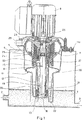
図1は、分離される粒子を含む液体のための流入口2と、そしてこの液体中に浮遊する粒子が除去された液体のための流出口3とを有する容器1を示す。この容器1の中には液体4があって、この液体中において、ある種の比較的に軽い粒子は表層に蓄積され、そしてある種の比較的に重い粒子は底層に蓄積されている。
【0013】
容器1は、開口部6を有する上部の壁5を有する。壁5には、本発明にしたがった分離装置が取り付けられ、この装置は下に延びて容器内に達している。分離装置には、遠心ロータ7と、この遠心ロータに連結されている入口部材8と、遠心ロータ7を回転させるためのモータ9と、そして垂直の回転軸Rを中心にした入口部材8とを有する。
【0014】
管状でありそして幾らか円すい形でもある、入口部材8は、ロックリング10によって遠心ロータに連結され、そして液体4の中に浸されるように、容器1内で下方に延びている。遠心ロータ7および入口部材8は双方とも、静止しているケーシング11により囲まれており、このケーシング11もまた、入口部材8の周囲において液体4の中に浸されるように、容器1内で下方に向かって延びている。
【0015】
分離装置の全体は、ケーシング11を含めて、容器の壁5の上側にある懸架装置11aに、たわむように吊り下げられている。したがって、もし遠心ロータ7およびその入口部材8が、動作中に、振動するか、または小さな振り子運動を行うならば、ケーシング11もまた同じように動くことになる。
【0016】
入口部材8に最も近く、ケーシング11は円筒形の周壁12を形成し、この周壁は、容器1の液体がない部分から液体4にまで下方に延びている。周壁12は、その下部にシール装置13を保持しており、このシール装置は、静止している周壁12と回転可能な入口部材8との間を密封するようになっている。
【0017】
図2に最もよく示されているように、シール装置13は、軸線方向に可動のスリーブ状のシール部材14を有する。シール部材14は、その上部14aにおいて、その外周を密封するように円筒形の周壁12の内側に接している。周壁12に連結されている環状のフランジ16の上に設けられているコイルスプリング15によって、図2に示されているように、シール部材14は軸線方向上方に押し上げられている。このため、シール部材14の下部14bは、回転可能な入口部材8の最低部に連結されている、もう1つのシール部材17に対して軸線方向に押しつけられている。したがって、これらのシール部材14と17は、それぞれ軸線方向に向いているシール面を介して互いに接している。
【0018】
シール部材14の下部14bは、中央の貫通孔を有し、この貫通孔には、容器1内に存在する液体の回転を分離装置の下において妨げるために設けられているウイング18によって架橋されている。ウイング18の延長部は、図5にも示されている。
【0019】
図3は、図2の線A−Aにそって切断された入口部材8の断面図を示す。図示されているように、入口部材8は3つの内部ウイング19を有し、これらのウイング19は、入口部材8全体を通って遠心ロータ7まで半径方向および軸線方向の双方に延びている(図1参照)。内部ウイング19は、分離装置の動作中に、液体を入口部材8の回転に同伴するようになっている。
【0020】
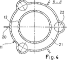
図4は、図2の線B−Bにそって切断されたケーシング11の断面図を示す。このケーシングはその外側にウイング20を有し、これらのウイングは、半径方向外側および軸線方向の双方に延びており、そして容器1内の液体の回転を妨審することをその目的としている。
【0021】
図1および2に示されているように、ケーシング11内にはスペース21が画されており、このスペースは、3つの流路22によって、分離装置の下にある容器1の内部に連通している。
【0022】
遠心ロータ7は、異なる構造を有する公知の種類の適宜な遠心ロータと交換することができるので、以下に詳細に説明されることはない。適宜な遠心ロータの詳細な説明に関しては、例えば、欧州特許EP312,233B1号、EP312,279B1号、国際特許WO96/33021号およびWO96/33022号を参照できる。
【0023】
入口部材8と遠心ロータ7との間の連結域において、遠心ロータ内に入口チャンバ23が画されている。この入口チャンバ23は、流入路24を介して、分離チャンバ25と連通している。遠心ロータ7は、分離された比較的に軽い液体のための出口26と、そして分離された比較的に重い液体のための出口27とを有する。
【0024】
周囲のケーシング11は、遠心ロータから出る、分離された軽い液体のための受入れチャンバ28と、そしてそこからの出口29とを有する。更に、ケーシング11は、遠心ロータから出る、分離された重い液体のための受入れチャンバ30を有する。受入れチャンバ30は、ケーシング11内の上記スペース21に連通している。
【0025】
上述の分離装置は、分離される液体よりも軽い液体粒子と当該液体よりも重い固体粒子との双方を含む液体を分離する際に、以下のように作動する。
【0026】
遠心ロータ7と回転軸Rの周りでこのロータに連結されている入口部材8とを駆動させるために、モータ9が始動されると、入口部材8が吸い上げ部材として作動するので、液体4から遠心ロータに液体が吸い上げられる。図1および2に示されているように、入口部材8の内部に、ほぼ円筒形の液面が形成され、この液面は、入口部材の下部から遠心ロータの入口チャンバ23までずっと延びている。このように、入口部材8の中に形成され、そして内部ウイング19(図3参照)によってこの部材8の回転に同伴される液体は、図1および2に矢印によって示されているように、軸線方向上方に向かって流動する。入口部材8の中央には、空気を満たされているスペースがあり、必要なら、このスペースは入口部材8の周囲にある空気と連通していてもよい。この目的のために、入口部材8は、入口部材の中心から入口部材の外側まで半径方向外側に向かっての延びている細い管を有してもよい。この種のパイプは、図1では入口部材8の上部に点線で示されている。
【0027】
入口部材8を通って遠心ロータ7の入口チャンバ23に入る液体は、このチャンバから流入路24を通って分離チャンバ25に導かれる。このチャンバ25中には、1群の円すい形の分離ディスクが配置されており、これらのディスクはその間に薄い分離スペースを形成する。軽い液体粒子は遠心力によって遠心ロータの回転軸に向かって移動させられ、そして連続相に合体した後に、出口26を通って排出されるが、他方、重い固体粒子は分離チャンバ25の半径方向最外側部分に向かって移動させられ、ここで遠心ロータの周壁に堆積するので、分離スペースにおいて、液体に浮遊している様々な種類の粒子は分離される。このように粒子が分離された液体は先ず、遠心ロータの回転軸から離れる方向に流動して上記分離スペースから外に出て、その後1つ又はそれ以上の捕集流路を通って再び回転軸に向かい、分離された比較的重い液体のための遠心ロータ出口27に至る。
【0028】
これに対して、分離された比較的に軽い液体はケーシング11の出口29を通って特定の受器に導かれるが、粒子が除かれた液体は、出口27から容器1内の液体4に戻るように導かれる。こうして、粒子を除かれた液体は受入れチャンバ30を通ってケーシング11内のスペース21に導かれ、そして、ここから流路22を通って液体4に導かれる。
【0029】
もし、より重い液体から分離された軽い液体の量が少ないときは、液体4から遠心ロータ7に吸い上げられる液体とほぼ同じ量の液体の流れが液体4に戻される。図1および2に示されているように、スペース21と周囲の容器1の液面間には、一定の水位の差が生ずる。
【0030】
入口部材8を囲み、そしてシール装置13の一部を支持する、静止している周壁12は、必ずしもケーシング11により支持される必要はない。代替として、この壁12は、容器1により支持してもよい。しかしながら、図に示されている配置は、シール装置13の機能にとって有利である。したがって、共働するシール部材14および17は共に、同一の懸架装置に取り付けられることが、1つの利点になる。回転可能な遠心ロータ7のための懸架装置が可とう性を有すると、シール装置13の回転部分も、可とう性を有するように吊り下げられる。従ってシール装置の回転しない部分も可とう性をもって吊り下げられる。
【0031】
上述のように、本発明による分離装置は、液体より重い粒子あるいは液体より軽い粒子のいずれを除去するにしても、これに係わりなく液体の分離のために用いることができる。もちろん、その時遠心ロータの構造は、当該の分離効率に適合していなければならない。また、液体から分離される粒子は、それが固体にしろ液体にしろ、当該の液体自体よりも貴重であり、したがって、分離作業は本当は液体浄化作業と呼べないようなこともあり得る。更に、粒子を除去された液体が容器1に戻されることは、本発明の必要条件ではない。
【図面の簡単な説明】
【図1】 本発明による分離装置と、この分離装置によって浄化される液体を収容する容器とを示す。
【図2】 図1における分離装置の一部を拡大して示したものである。
【図3】 図2における対応する線にそって切断された断面A−Aを示す。
【図4】 図2における対応する線にそって切断された断面B−Bを示す。
【図5】 図2における対応する線にそって切断された断面C−Cを示す。[0001]
The invention relates to a separation device for removing solids or liquid particles and / or heavier solids or liquid particles that are suspended in the liquid and / or lighter from the liquid, the separation device A centrifugal rotor that rotates about a vertical rotation axis, a drive device that rotates the centrifugal rotor about the rotation axis, and a tubular inlet member that is connected to the centrifugal rotor, the centrifugal rotor And a tubular inlet member extending downwardly from the inlet member and penetrating into the liquid through the inlet member and sucked into the centrifugal rotor.
[0002]
Such a separation device is known, for example, from US Pat. No. 1,927,822, US Pat. No. 3,424,375 or EP 0 047 677 A2. The separation device can be installed directly on the container containing the liquid containing the particles to be removed.
[0003]
It is often impossible to keep the liquid level in such a liquid container at a predetermined water level at all times. When using a previously known type of separation device as described above, the tubular inlet member is in this case more or less immersed in the liquid and when the liquid level is at a fairly low level, the inlet member is liquid. Since it must reach below the surface, it means that when the liquid level is at a fairly high water level, an undesirably large part of the inlet member is immersed in the liquid.
[0004]
One reason that the rotatable inlet member should not be immersed more than necessary in the liquid described above is that this causes rotation of the liquid within the container. This reduces the wicking effect of the inlet member and causes undesirable fragmentation of the particles that must later be separated from the liquid in the centrifuge. Another reason is that it requires more energy than necessary to operate the centrifugal rotor.
[0005]
The object of the present invention is to avoid the above-mentioned problems which arise with regard to the initially defined type of separation device.
[0006]
The purpose is to seal at least a portion of the rotatable inlet member between the non-rotating wall that is enclosed in the liquid and the non-rotating wall and the rotatable inlet member. This is achieved according to the present invention using a sealing device.
[0007]
The present invention makes it possible to minimize the surface of the rotatable inlet member in contact with the liquid containing the particles to be removed, regardless of the liquid level. As a result, the rotation of the liquid present in the container and pumped upward through the inlet member is minimized. Furthermore, the present invention avoids liquid being drawn up outside the inlet member as a result of rotation of the inlet member.
[0008]
The sealing device has a suitable structure. For example, an annular rubber so-called lip gasket or some elastic material may be supported by a non-rotating wall to surround the inlet member and seal the outside of the inlet member radially. . Alternatively, a similar annular lip gasket may be attached to the rotatable inlet member such that it is pressed radially against the surrounding non-rotating wall by centrifugal force.
[0009]
In a preferred embodiment of the invention, the sealing device comprises an annular seal member that is axially movable, a non-rotating wall or a non-rotating member connected to the wall, and a rotatable inlet member. Means for exerting a sealing force in the axial direction. The sealing member may rotate with the inlet member, but preferably does not rotate but is axially pressed against the sealing surface of the rotatable inlet member, preferably against its end surface.
[0010]
For sealing devices, in order to obtain the best functional requirements, if the centrifugal rotor is suspended from a flexible suspension, the non-rotating wall must also be suspended from the same suspension. It is. In this way, relative pendulum movement between the rotatable inlet member and the non-rotating wall is avoided during operation of the centrifugal rotor.
[0011]
The present invention is described below with reference to the accompanying drawings.
[0012]
FIG. 1 shows a container 1 having an
[0013]
The container 1 has an
[0014]
An
[0015]
The entire separation device, including the
[0016]
Closest to the
[0017]
As best shown in FIG. 2, the
[0018]
The lower part 14b of the seal member 14 has a central through hole, and this through hole is bridged by a
[0019]
FIG. 3 shows a cross-sectional view of the
[0020]
FIG. 4 shows a cross-sectional view of the
[0021]
As shown in FIGS. 1 and 2, a
[0022]
The centrifugal rotor 7 can be replaced with a known type of appropriate centrifugal rotor having a different structure and will not be described in detail below. For a detailed description of suitable centrifugal rotors, reference can be made, for example, to European Patents EP312,233B1, EP312,279B1, International Patents WO96 / 33021 and WO96 / 33022.
[0023]
In the connection area between the
[0024]
The surrounding
[0025]
The above-described separation device operates as follows when separating a liquid containing both liquid particles lighter than the liquid to be separated and solid particles heavier than the liquid.
[0026]
When the motor 9 is started to drive the centrifugal rotor 7 and the
[0027]
Liquid entering the
[0028]
In contrast, the separated relatively light liquid is guided to a specific receiver through the
[0029]
If the amount of light liquid separated from the heavier liquid is small, almost the same amount of liquid flow as liquid drawn from the liquid 4 to the centrifugal rotor 7 is returned to the liquid 4. As shown in FIGS. 1 and 2, a certain water level difference occurs between the
[0030]
The stationary
[0031]
As described above, the separation apparatus according to the present invention can be used for liquid separation regardless of whether particles heavier than liquid or particles lighter than liquid are removed. Of course, the structure of the centrifugal rotor must then be adapted to the separation efficiency concerned. Also, particles that are separated from a liquid, whether it is a solid or a liquid, are more valuable than the liquid itself, and therefore the separation operation may not really be called a liquid purification operation. Furthermore, it is not a requirement of the present invention that the liquid from which the particles have been removed be returned to the container 1.
[Brief description of the drawings]
FIG. 1 shows a separation device according to the invention and a container containing a liquid to be purified by the separation device.
FIG. 2 is an enlarged view of a part of the separation device in FIG.
FIG. 3 shows a cross section AA cut along the corresponding line in FIG.
4 shows a cross section BB cut along the corresponding line in FIG.
FIG. 5 shows a cross-section CC cut along the corresponding line in FIG.
Claims (4)
前記液体(4)内において、前記回転可能な入口部材(8)の少なくとも一部を囲む回転不能の静止壁(12)と、前記回転不能の静止壁(12)と前記回転可能な入口部材(8)との間を密封するシール装置(13)とを備え、
前記回転可能な入口部材は、前記液体から離れる方向に直径が増加する円錐状になっており、
前記遠心ロータ(7)の動作中に、前記回転可能な入口部材(8)と前記回転不能の壁(12)との間の相対的振り子運動を回避するために、前記遠心ロータ(7)が可とう性の懸架装置(11a)から吊り下げられ、そして前記回転不能の壁(12)も可とう性の同じ懸架装置(11a)から吊り下げられていることを特徴とする分離装置。A centrifugal rotor (7) that rotates about a vertical rotation axis (R), a drive device (9) that rotates the centrifugal rotor (7) about the rotation axis (R), and the centrifugal rotor ( 7) and a tubular inlet member (8) extending downward from the centrifugal rotor (7) into the liquid (4) and pumping the liquid (4) into the interior of the centrifugal rotor (7). In the separation device,
In the liquid (4), a non-rotatable stationary wall (12) surrounding at least a part of the rotatable inlet member (8), the non-rotatable stationary wall (12) and the rotatable inlet member ( 8) and a sealing device (13) for sealing between
The rotatable inlet member has a conical shape with a diameter increasing in a direction away from the liquid ;
In order to avoid relative pendulum movement between the rotatable inlet member (8) and the non-rotatable wall (12) during operation of the centrifugal rotor (7), the centrifugal rotor (7) Separation device characterized in that it is suspended from a flexible suspension (11a) and the non-rotatable wall (12) is also suspended from the same flexible suspension (11a) .
Applications Claiming Priority (3)
| Application Number | Priority Date | Filing Date | Title |
|---|---|---|---|
| SE9901234A SE514134C2 (en) | 1999-04-07 | 1999-04-07 | Separating device for purifying a liquid from suspended or liquid particles suspended therein which are lighter and / or heavier than the liquid |
| SE9901234-6 | 1999-04-07 | ||
| PCT/SE2000/000552 WO2000059640A1 (en) | 1999-04-07 | 2000-03-21 | A separation device |
Publications (3)
| Publication Number | Publication Date |
|---|---|
| JP2002540924A JP2002540924A (en) | 2002-12-03 |
| JP2002540924A5 JP2002540924A5 (en) | 2007-04-05 |
| JP4800486B2 true JP4800486B2 (en) | 2011-10-26 |
Family
ID=20415130
Family Applications (1)
| Application Number | Title | Priority Date | Filing Date |
|---|---|---|---|
| JP2000609193A Expired - Fee Related JP4800486B2 (en) | 1999-04-07 | 2000-03-21 | Separation device |
Country Status (10)
| Country | Link |
|---|---|
| US (1) | US6955637B1 (en) |
| EP (1) | EP1175264B1 (en) |
| JP (1) | JP4800486B2 (en) |
| KR (1) | KR100623114B1 (en) |
| AT (1) | ATE395979T1 (en) |
| AU (1) | AU4156700A (en) |
| DE (1) | DE60038962D1 (en) |
| RU (1) | RU2233709C2 (en) |
| SE (1) | SE514134C2 (en) |
| WO (1) | WO2000059640A1 (en) |
Families Citing this family (15)
| Publication number | Priority date | Publication date | Assignee | Title |
|---|---|---|---|---|
| SE521578C2 (en) * | 2002-03-21 | 2003-11-11 | Alfa Laval Corp Ab | centrifugal |
| US7531092B2 (en) * | 2005-11-01 | 2009-05-12 | Hayward Industries, Inc. | Pump |
| US8186517B2 (en) * | 2005-11-01 | 2012-05-29 | Hayward Industries, Inc. | Strainer housing assembly and stand for pump |
| US8182212B2 (en) * | 2006-09-29 | 2012-05-22 | Hayward Industries, Inc. | Pump housing coupling |
| US8297920B2 (en) | 2008-11-13 | 2012-10-30 | Hayward Industries, Inc. | Booster pump system for pool applications |
| SE533562C2 (en) * | 2009-03-06 | 2010-10-26 | Alfa Laval Corp Ab | centrifugal |
| ES2706482T3 (en) | 2010-02-25 | 2019-03-29 | Alfa Laval Corp Ab | Equipment and method for cleaning exhaust gas and fluid gas scrubber |
| EP2402288B1 (en) * | 2010-07-02 | 2016-11-16 | Alfa Laval Corporate AB | Cleaning equipment for gas scrubber fluid |
| EP2567754B1 (en) * | 2011-09-08 | 2018-02-28 | Alfa Laval Corporate AB | A centrifugal separator |
| US9079128B2 (en) | 2011-12-09 | 2015-07-14 | Hayward Industries, Inc. | Strainer basket and related methods of use |
| US9022723B2 (en) * | 2012-03-27 | 2015-05-05 | General Electric Company | System for drawing solid feed into and/or out of a solid feed pump |
| US10718337B2 (en) | 2016-09-22 | 2020-07-21 | Hayward Industries, Inc. | Self-priming dedicated water feature pump |
| USD986289S1 (en) | 2020-11-24 | 2023-05-16 | Aquastar Pool Products, Inc. | Centrifugal pump |
| US11193504B1 (en) | 2020-11-24 | 2021-12-07 | Aquastar Pool Products, Inc. | Centrifugal pump having a housing and a volute casing wherein the volute casing has a tear-drop shaped inner wall defined by a circular body region and a converging apex with the inner wall comprising a blocker below at least one perimeter end of one diffuser blade |
| USD946629S1 (en) | 2020-11-24 | 2022-03-22 | Aquastar Pool Products, Inc. | Centrifugal pump |
Citations (5)
| Publication number | Priority date | Publication date | Assignee | Title |
|---|---|---|---|---|
| US1927822A (en) * | 1926-02-16 | 1933-09-26 | Merco Centrifugal Separator Co | Centrifuge apparatus |
| JPS57117355A (en) * | 1980-09-10 | 1982-07-21 | Poribatsuku Corp | Solid-liquid separator and its method |
| JPS63287592A (en) * | 1987-05-20 | 1988-11-24 | Ebara Corp | Continuous centrifugal separator for mixed liquid in aeration tank having pump-up mechanism |
| JPH07303849A (en) * | 1994-05-13 | 1995-11-21 | Shusaku Sakamoto | Continuous dust removing water purifire |
| JPH109831A (en) * | 1996-06-24 | 1998-01-16 | Hitachi Ltd | Fly height measuring apparatus for magnetic recorder |
Family Cites Families (19)
| Publication number | Priority date | Publication date | Assignee | Title |
|---|---|---|---|---|
| US791496A (en) * | 1904-08-15 | 1905-06-06 | Anders Ponten | Centrifugal cream-separator. |
| US1056233A (en) * | 1912-06-12 | 1913-03-18 | Lamartine C Trent | Apparatus for separating solids from liquid solutions. |
| US1050720A (en) * | 1912-11-05 | 1913-01-14 | Harald De Raasloff | Art of centrifugal separation. |
| US1712184A (en) * | 1926-10-07 | 1929-05-07 | Reinhold M Wendel | Centrifugal concentrator |
| US2881974A (en) | 1955-08-08 | 1959-04-14 | Ruf Walter | Centrifuge |
| US2928592A (en) * | 1957-05-01 | 1960-03-15 | Dorr Oliver Inc | Pressure centrifuge |
| DE1632325B1 (en) | 1967-06-02 | 1970-05-27 | Turbo Separator Ag | Continuously working, screenless screw centrifuge |
| US3768726A (en) * | 1970-05-06 | 1973-10-30 | Autometrics Co | Method and apparatus for the removal of entrained gases from mineral slurries, pulps, liquids, and the like |
| US3756505A (en) * | 1970-06-01 | 1973-09-04 | Robatel S L P I Zone Ind | Centrifugal extractors with means for moving the materials |
| SE442830B (en) * | 1984-06-15 | 1986-02-03 | Alfa Laval Separation Ab | LIQUID LEVEL HOLDING CENTRIFUGAL Separator |
| DE3542133A1 (en) * | 1985-11-28 | 1987-06-04 | Duerr Dental Gmbh Co Kg | DEVICE FOR SEPARATING FINE SOLID PARTICLES FROM WASTEWATER |
| SE8703965D0 (en) | 1987-10-13 | 1987-10-13 | Alfa Laval Separation Ab | centrifugal |
| SE459233B (en) | 1987-10-13 | 1989-06-19 | Alfa Laval Separation Ab | CENTRIFUGAL SEPARATOR INCLUDING AN INTERMEDIATE BODY |
| AT395941B (en) * | 1991-04-12 | 1993-04-26 | Trawoeger Werner | SEPARATOR FOR SEPARATING A SOLID-LIQUID MIXTURE |
| US5364335A (en) * | 1993-12-07 | 1994-11-15 | Dorr-Oliver Incorporated | Disc-decanter centrifuge |
| SE504231C2 (en) | 1995-04-18 | 1996-12-09 | Tetra Laval Holdings & Finance | centrifugal |
| SE504227C2 (en) | 1995-04-18 | 1996-12-09 | Tetra Laval Holdings & Finance | centrifugal |
| SE513789C2 (en) * | 1999-03-08 | 2000-11-06 | Alfa Laval Ab | A centrifuge rotor drive unit of a centrifugal separator |
| SE514135C2 (en) * | 1999-04-07 | 2001-01-08 | Alfa Laval Ab | Method and apparatus for separating a surface layer of a liquid body |
-
1999
- 1999-04-07 SE SE9901234A patent/SE514134C2/en not_active IP Right Cessation
-
2000
- 2000-03-21 RU RU2001130054/12A patent/RU2233709C2/en not_active IP Right Cessation
- 2000-03-21 US US09/958,449 patent/US6955637B1/en not_active Expired - Lifetime
- 2000-03-21 WO PCT/SE2000/000552 patent/WO2000059640A1/en active IP Right Grant
- 2000-03-21 JP JP2000609193A patent/JP4800486B2/en not_active Expired - Fee Related
- 2000-03-21 AU AU41567/00A patent/AU4156700A/en not_active Abandoned
- 2000-03-21 KR KR1020017012757A patent/KR100623114B1/en not_active IP Right Cessation
- 2000-03-21 EP EP00921228A patent/EP1175264B1/en not_active Expired - Lifetime
- 2000-03-21 DE DE60038962T patent/DE60038962D1/en not_active Expired - Lifetime
- 2000-03-21 AT AT00921228T patent/ATE395979T1/en not_active IP Right Cessation
Patent Citations (5)
| Publication number | Priority date | Publication date | Assignee | Title |
|---|---|---|---|---|
| US1927822A (en) * | 1926-02-16 | 1933-09-26 | Merco Centrifugal Separator Co | Centrifuge apparatus |
| JPS57117355A (en) * | 1980-09-10 | 1982-07-21 | Poribatsuku Corp | Solid-liquid separator and its method |
| JPS63287592A (en) * | 1987-05-20 | 1988-11-24 | Ebara Corp | Continuous centrifugal separator for mixed liquid in aeration tank having pump-up mechanism |
| JPH07303849A (en) * | 1994-05-13 | 1995-11-21 | Shusaku Sakamoto | Continuous dust removing water purifire |
| JPH109831A (en) * | 1996-06-24 | 1998-01-16 | Hitachi Ltd | Fly height measuring apparatus for magnetic recorder |
Also Published As
| Publication number | Publication date |
|---|---|
| US6955637B1 (en) | 2005-10-18 |
| SE9901234D0 (en) | 1999-04-07 |
| ATE395979T1 (en) | 2008-06-15 |
| EP1175264B1 (en) | 2008-05-21 |
| KR20020007357A (en) | 2002-01-26 |
| KR100623114B1 (en) | 2006-09-26 |
| EP1175264A1 (en) | 2002-01-30 |
| SE9901234L (en) | 2000-10-08 |
| DE60038962D1 (en) | 2008-07-03 |
| WO2000059640A1 (en) | 2000-10-12 |
| RU2233709C2 (en) | 2004-08-10 |
| AU4156700A (en) | 2000-10-23 |
| JP2002540924A (en) | 2002-12-03 |
| SE514134C2 (en) | 2001-01-08 |
Similar Documents
| Publication | Publication Date | Title |
|---|---|---|
| JP4800486B2 (en) | Separation device | |
| JP5105207B2 (en) | Separation device with direct drive | |
| US4842478A (en) | Dental suction apparatus | |
| EP0221723B1 (en) | Centrifuge rotor inlet device | |
| US4400167A (en) | Centrifugal separator | |
| US5713826A (en) | Vertical basket centrifuge with feed acceleration and a removable liner | |
| CA2112886A1 (en) | Centrifugal separator | |
| JPS6112494B2 (en) | ||
| JP5694349B2 (en) | Helmetic centrifuge | |
| US3682373A (en) | Centrifugal separator | |
| US4534755A (en) | Centrifuges | |
| JP4938175B2 (en) | Method and apparatus for separating the surface layer of a liquid body | |
| JPH0811201B2 (en) | Separator | |
| JP2002540923A5 (en) | ||
| JPH11514572A (en) | Low shear force supply system used with centrifuge | |
| JP4342107B2 (en) | Centrifuge outlet with reaction driven rotor | |
| JP4703573B2 (en) | centrifuge | |
| JP4060276B2 (en) | centrifuge | |
| GB2115319A (en) | Centrifuge and method of operating same | |
| US3485445A (en) | Centrifuge apparatus with flexible boot | |
| RU2778648C1 (en) | Separator | |
| SU990316A1 (en) | Centrifuge for separating suspensions | |
| RU35604U1 (en) | CENTRIFUGE FOR SEPARATION OF SUSPENSIONS | |
| US20040144717A1 (en) | Apparatus for separating immiscible liquids | |
| JPS6054716A (en) | Centrifugal defoaming device |
Legal Events
| Date | Code | Title | Description |
|---|---|---|---|
| A521 | Request for written amendment filed |
Free format text: JAPANESE INTERMEDIATE CODE: A523 Effective date: 20070208 |
|
| A621 | Written request for application examination |
Free format text: JAPANESE INTERMEDIATE CODE: A621 Effective date: 20070208 |
|
| RD03 | Notification of appointment of power of attorney |
Free format text: JAPANESE INTERMEDIATE CODE: A7423 Effective date: 20070208 |
|
| A977 | Report on retrieval |
Free format text: JAPANESE INTERMEDIATE CODE: A971007 Effective date: 20091007 |
|
| A131 | Notification of reasons for refusal |
Free format text: JAPANESE INTERMEDIATE CODE: A131 Effective date: 20091014 |
|
| A601 | Written request for extension of time |
Free format text: JAPANESE INTERMEDIATE CODE: A601 Effective date: 20091221 |
|
| A602 | Written permission of extension of time |
Free format text: JAPANESE INTERMEDIATE CODE: A602 Effective date: 20100104 |
|
| A521 | Request for written amendment filed |
Free format text: JAPANESE INTERMEDIATE CODE: A523 Effective date: 20100414 |
|
| A131 | Notification of reasons for refusal |
Free format text: JAPANESE INTERMEDIATE CODE: A131 Effective date: 20101124 |
|
| A521 | Request for written amendment filed |
Free format text: JAPANESE INTERMEDIATE CODE: A523 Effective date: 20110215 |
|
| TRDD | Decision of grant or rejection written | ||
| A01 | Written decision to grant a patent or to grant a registration (utility model) |
Free format text: JAPANESE INTERMEDIATE CODE: A01 Effective date: 20110706 |
|
| A01 | Written decision to grant a patent or to grant a registration (utility model) |
Free format text: JAPANESE INTERMEDIATE CODE: A01 |
|
| A61 | First payment of annual fees (during grant procedure) |
Free format text: JAPANESE INTERMEDIATE CODE: A61 Effective date: 20110804 |
|
| FPAY | Renewal fee payment (event date is renewal date of database) |
Free format text: PAYMENT UNTIL: 20140812 Year of fee payment: 3 |
|
| R150 | Certificate of patent or registration of utility model |
Free format text: JAPANESE INTERMEDIATE CODE: R150 |
|
| R250 | Receipt of annual fees |
Free format text: JAPANESE INTERMEDIATE CODE: R250 |
|
| R250 | Receipt of annual fees |
Free format text: JAPANESE INTERMEDIATE CODE: R250 |
|
| R250 | Receipt of annual fees |
Free format text: JAPANESE INTERMEDIATE CODE: R250 |
|
| LAPS | Cancellation because of no payment of annual fees |