JP4797114B2 - Method for manufacturing transfer mask and method for manufacturing semiconductor device - Google Patents
Method for manufacturing transfer mask and method for manufacturing semiconductor device Download PDFInfo
- Publication number
- JP4797114B2 JP4797114B2 JP2010226226A JP2010226226A JP4797114B2 JP 4797114 B2 JP4797114 B2 JP 4797114B2 JP 2010226226 A JP2010226226 A JP 2010226226A JP 2010226226 A JP2010226226 A JP 2010226226A JP 4797114 B2 JP4797114 B2 JP 4797114B2
- Authority
- JP
- Japan
- Prior art keywords
- thin film
- pattern
- transfer
- film
- chromium
- Prior art date
- Legal status (The legal status is an assumption and is not a legal conclusion. Google has not performed a legal analysis and makes no representation as to the accuracy of the status listed.)
- Expired - Fee Related
Links
Images


Classifications
-
- G—PHYSICS
- G03—PHOTOGRAPHY; CINEMATOGRAPHY; ANALOGOUS TECHNIQUES USING WAVES OTHER THAN OPTICAL WAVES; ELECTROGRAPHY; HOLOGRAPHY
- G03F—PHOTOMECHANICAL PRODUCTION OF TEXTURED OR PATTERNED SURFACES, e.g. FOR PRINTING, FOR PROCESSING OF SEMICONDUCTOR DEVICES; MATERIALS THEREFOR; ORIGINALS THEREFOR; APPARATUS SPECIALLY ADAPTED THEREFOR
- G03F1/00—Originals for photomechanical production of textured or patterned surfaces, e.g., masks, photo-masks, reticles; Mask blanks or pellicles therefor; Containers specially adapted therefor; Preparation thereof
- G03F1/26—Phase shift masks [PSM]; PSM blanks; Preparation thereof
- G03F1/32—Attenuating PSM [att-PSM], e.g. halftone PSM or PSM having semi-transparent phase shift portion; Preparation thereof
-
- G—PHYSICS
- G03—PHOTOGRAPHY; CINEMATOGRAPHY; ANALOGOUS TECHNIQUES USING WAVES OTHER THAN OPTICAL WAVES; ELECTROGRAPHY; HOLOGRAPHY
- G03F—PHOTOMECHANICAL PRODUCTION OF TEXTURED OR PATTERNED SURFACES, e.g. FOR PRINTING, FOR PROCESSING OF SEMICONDUCTOR DEVICES; MATERIALS THEREFOR; ORIGINALS THEREFOR; APPARATUS SPECIALLY ADAPTED THEREFOR
- G03F1/00—Originals for photomechanical production of textured or patterned surfaces, e.g., masks, photo-masks, reticles; Mask blanks or pellicles therefor; Containers specially adapted therefor; Preparation thereof
- G03F1/54—Absorbers, e.g. of opaque materials
-
- G—PHYSICS
- G03—PHOTOGRAPHY; CINEMATOGRAPHY; ANALOGOUS TECHNIQUES USING WAVES OTHER THAN OPTICAL WAVES; ELECTROGRAPHY; HOLOGRAPHY
- G03F—PHOTOMECHANICAL PRODUCTION OF TEXTURED OR PATTERNED SURFACES, e.g. FOR PRINTING, FOR PROCESSING OF SEMICONDUCTOR DEVICES; MATERIALS THEREFOR; ORIGINALS THEREFOR; APPARATUS SPECIALLY ADAPTED THEREFOR
- G03F1/00—Originals for photomechanical production of textured or patterned surfaces, e.g., masks, photo-masks, reticles; Mask blanks or pellicles therefor; Containers specially adapted therefor; Preparation thereof
- G03F1/68—Preparation processes not covered by groups G03F1/20 - G03F1/50
- G03F1/76—Patterning of masks by imaging
-
- G—PHYSICS
- G03—PHOTOGRAPHY; CINEMATOGRAPHY; ANALOGOUS TECHNIQUES USING WAVES OTHER THAN OPTICAL WAVES; ELECTROGRAPHY; HOLOGRAPHY
- G03F—PHOTOMECHANICAL PRODUCTION OF TEXTURED OR PATTERNED SURFACES, e.g. FOR PRINTING, FOR PROCESSING OF SEMICONDUCTOR DEVICES; MATERIALS THEREFOR; ORIGINALS THEREFOR; APPARATUS SPECIALLY ADAPTED THEREFOR
- G03F1/00—Originals for photomechanical production of textured or patterned surfaces, e.g., masks, photo-masks, reticles; Mask blanks or pellicles therefor; Containers specially adapted therefor; Preparation thereof
- G03F1/68—Preparation processes not covered by groups G03F1/20 - G03F1/50
- G03F1/80—Etching
-
- G—PHYSICS
- G03—PHOTOGRAPHY; CINEMATOGRAPHY; ANALOGOUS TECHNIQUES USING WAVES OTHER THAN OPTICAL WAVES; ELECTROGRAPHY; HOLOGRAPHY
- G03F—PHOTOMECHANICAL PRODUCTION OF TEXTURED OR PATTERNED SURFACES, e.g. FOR PRINTING, FOR PROCESSING OF SEMICONDUCTOR DEVICES; MATERIALS THEREFOR; ORIGINALS THEREFOR; APPARATUS SPECIALLY ADAPTED THEREFOR
- G03F1/00—Originals for photomechanical production of textured or patterned surfaces, e.g., masks, photo-masks, reticles; Mask blanks or pellicles therefor; Containers specially adapted therefor; Preparation thereof
- G03F1/68—Preparation processes not covered by groups G03F1/20 - G03F1/50
- G03F1/82—Auxiliary processes, e.g. cleaning or inspecting
Description
本発明は、耐光性を向上させた転写用マスク及び転写用マスクの製造方法等に関する。特に、波長200nm以下の短波長の露光光を露光光源とする露光装置に好適に用いられる転写用マスク及びその製造方法、並びに半導体デバイスの製造方法に関する。 The present invention relates to a transfer mask having improved light resistance, a method for manufacturing the transfer mask, and the like. In particular, the present invention relates to a transfer mask that is suitably used in an exposure apparatus that uses exposure light having a short wavelength of 200 nm or less as an exposure light source, a manufacturing method thereof, and a semiconductor device manufacturing method.
一般に、半導体装置の製造工程では、フォトリソグラフィー法を用いて微細パターンの形成が行われている。また、この微細パターンの形成には通常何枚もの転写用マスク(フォトマスク)が使用される。この転写マスクは、一般に透光性基板上に、金属薄膜等からなる微細パターンを設けたものであり、この転写マスクの製造においてもフォトリソグラフィー法が用いられている。 In general, in a manufacturing process of a semiconductor device, a fine pattern is formed using a photolithography method. Also, a number of transfer masks (photomasks) are usually used for forming this fine pattern. This transfer mask is generally provided with a fine pattern made of a metal thin film or the like on a translucent substrate, and a photolithography method is also used in the manufacture of this transfer mask.
フォトリソグラフィー法による転写マスクの製造には、ガラス基板等の透光性基板上に転写パターン(マスクパターン)を形成するための薄膜(例えば遮光膜など)を有するマスクブランクが用いられる。
このマスクブランクを用いた転写マスクの製造は、マスクブランク上に形成されたレジスト膜に対し、所望のパターン描画を施す露光工程と、所望のパターン描画に従って前記レジスト膜を現像してレジストパターンを形成する現像工程と、レジストパターンに従って前記薄膜をエッチングするエッチング工程と、残存したレジストパターンを剥離除去する工程とを有して行われている。
上記現像工程では、マスクブランク上に形成されたレジスト膜に対し所望のパターン描画(露光)を施した後に現像液を供給して、現像液に可溶なレジスト膜の部位を溶解し、レジストパターンを形成する。また、上記エッチング工程では、このレジストパターンをマスクとして、ドライエッチング又はウェットエッチングによって、レジストパターンが形成されておらず薄膜が露出した部位を溶解し、これにより所望の転写パターンを透光性基板上に形成する。こうして、転写用マスクが作製される。
In manufacturing a transfer mask by photolithography, a mask blank having a thin film (for example, a light shielding film) for forming a transfer pattern (mask pattern) on a light-transmitting substrate such as a glass substrate is used.
In the manufacture of a transfer mask using this mask blank, an exposure process for drawing a desired pattern on the resist film formed on the mask blank, and a resist pattern is formed by developing the resist film according to the desired pattern drawing. A developing step, an etching step of etching the thin film according to the resist pattern, and a step of peeling and removing the remaining resist pattern.
In the developing step, a resist pattern formed on the mask blank is subjected to a desired pattern drawing (exposure), and then a developing solution is supplied to dissolve a portion of the resist film that is soluble in the developing solution. Form. Further, in the etching step, by using this resist pattern as a mask, the portion where the resist pattern is not formed and the thin film is exposed is dissolved by dry etching or wet etching, thereby forming a desired transfer pattern on the translucent substrate. To form. Thus, a transfer mask is produced.
半導体装置のパターンを微細化するに当たっては、転写用マスクに形成される転写パターンの微細化に加え、フォトリソグラフィーで使用される露光光源波長の短波長化が必要となる。半導体装置製造の際の露光光源としては、近年ではKrFエキシマレーザー(波長248nm)から、ArFエキシマレーザー(波長193nm)へと短波長化が進んでいる。 When miniaturizing a pattern of a semiconductor device, it is necessary to shorten the wavelength of an exposure light source used in photolithography in addition to miniaturization of a transfer pattern formed on a transfer mask. In recent years, as an exposure light source for manufacturing semiconductor devices, the wavelength has been shortened from an KrF excimer laser (wavelength 248 nm) to an ArF excimer laser (wavelength 193 nm).
また、転写用マスクの種類としては、従来の透光性基板上にクロム系材料からなる遮光膜パターンを有するバイナリ型マスクのほかに、ハーフトーン型位相シフトマスクが知られている。このハーフトーン型位相シフトマスクは、透光性基板上に光半透過膜(ハーフトーン型位相シフト膜)を有する構造のもので、この光半透過膜は、実質的に露光に寄与しない強度の光(例えば、露光波長に対して1%〜20%)を透過させ、この透過光に所定の位相差を付与するものであり、例えばモリブデンシリサイド化合物を含む材料等が用いられる。このハーフトーン型位相シフトマスクは、光半透過膜をパターニングした光半透過部と、光半透過膜が形成されておらず露光光を透過させる光透過部とによって、光半透過部を透過した光の位相が、光透過部を透過した光の位相に対して、実質的に反転した関係になるようにする(即ち位相をシフトさせる)ことによって、光半透過部と光透過部との境界部近傍を通過し回折現象によって互いに相手の領域に回りこんだ光が互いに打ち消しあうようにし、境界部における光強度をほぼゼロとし境界部のコントラスト即ち解像度を向上させるものである。 As a type of transfer mask, a halftone phase shift mask is known in addition to a binary mask having a light-shielding film pattern made of a chromium-based material on a conventional translucent substrate. This halftone phase shift mask has a structure having a light transflective film (halftone phase shift film) on a translucent substrate, and this light transflective film has a strength that does not substantially contribute to exposure. Light (for example, 1% to 20% with respect to the exposure wavelength) is transmitted, and a predetermined phase difference is imparted to the transmitted light. For example, a material containing a molybdenum silicide compound is used. This halftone phase shift mask transmits the light semi-transmissive part by the light semi-transmissive part patterned with the light semi-transmissive film and the light transmissive part that does not have the light semi-transmissive film and transmits the exposure light. The boundary between the light semi-transmissive portion and the light transmissive portion is obtained by making the light phase have a substantially inverted relationship (that is, shifting the phase) with respect to the phase of the light transmitted through the light transmissive portion. The light that has passed through the vicinity of the light and has entered the other region due to the diffraction phenomenon cancels each other, and the light intensity at the boundary is made substantially zero, thereby improving the contrast of the boundary, that is, the resolution.
さらに、ArFエキシマレーザ(波長193nm)を露光光とする露光技術においては、転写パターンの微細化が進み、露光光の波長よりも小さいパターン線幅に対応することが求められ、斜入射照明法、位相シフト法等の超解像技術、さらにNA=1以上の超高NA技術(液浸露光等)が開発されてきている。
転写パターンの微細化が進むに従い、レジストパターンの幅は狭くなってきている。このため、従来のレジスト膜の膜厚ではアスペクト比が高くなってしまい、レジストパターンをマスクとして遮光膜をドライエッチングして転写パターンを形成することが難しくなってきている。
Furthermore, in an exposure technique using an ArF excimer laser (wavelength 193 nm) as exposure light, miniaturization of a transfer pattern has progressed, and it is required to correspond to a pattern line width smaller than the wavelength of exposure light. Super-resolution techniques such as a phase shift method, and ultra-high NA techniques (immersion exposure etc.) with NA = 1 or higher have been developed.
As the transfer pattern becomes finer, the width of the resist pattern has become narrower. For this reason, the aspect ratio becomes high with the film thickness of the conventional resist film, and it becomes difficult to form a transfer pattern by dry etching the light shielding film using the resist pattern as a mask.
この問題の解決手段の1つとして、フッ素系ガスでドライエッチング可能な遮光膜を遷移金属とケイ素を含有する膜で形成し、その遮光膜の上にクロム系材料からなるエッチングマスク膜を形成した構成のバイナリ型のマスクブランクが開発されている(特許文献1)。このマスクブランクから転写用マスクを作製する方法は、まず、エッチングマスク膜の上にレジストパターンを形成し、レジストパターンをマスクとして、塩素と酸素の混合ガスをエッチングガスとしたドライエッチングを行い、エッチングマスク膜に転写パターンを形成する。次に、エッチングマスク膜の転写パターンをマスクとして、フッ素系ガスをエッチングガスとしたドライエッチングを行い、遮光膜に転写パターンを形成する。そして、エッチングマスク膜を除去し、所定の洗浄工程を経て、バイナリ型の転写用マスクが作製される。 As one solution to this problem, a light-shielding film that can be dry-etched with a fluorine-based gas is formed of a film containing a transition metal and silicon, and an etching mask film made of a chromium-based material is formed on the light-shielding film. A binary mask blank having a configuration has been developed (Patent Document 1). A method for producing a transfer mask from this mask blank is as follows. First, a resist pattern is formed on an etching mask film, dry etching using a mixed gas of chlorine and oxygen as an etching gas is performed using the resist pattern as a mask, and etching is performed. A transfer pattern is formed on the mask film. Next, using the transfer pattern of the etching mask film as a mask, dry etching using a fluorine-based gas as an etching gas is performed to form a transfer pattern on the light shielding film. Then, the etching mask film is removed, and a binary transfer mask is manufactured through a predetermined cleaning process.
ところで、近年のパターンの微細化に伴い、バイナリ型マスクやハーフトーン型位相シフトマスク等の転写用マスクの製造コストが著しく上昇してきていることから、転写マスクの長寿命化のニーズが高まってきている。 By the way, with the recent miniaturization of patterns, the manufacturing cost of transfer masks such as binary masks and halftone phase shift masks has increased remarkably, and the need for extending the life of transfer masks has increased. Yes.
転写用マスクの寿命を決定する要因としては、転写用マスクの繰返し洗浄による繰返し使用による転写用マスク劣化の問題がある。従来においては、例えばヘイズ(硫化アンモニウムを主体とし転写マスク上に発生する異物)が発生するとヘイズを除去するための洗浄を行っていた。しかし、洗浄による膜減り(膜の溶出)は避けられず、いわば洗浄回数が転写マスクの寿命を決定していた。
近年、ヘイズ対策技術の向上によって転写用マスクの洗浄回数が低減しており、転写用マスクの繰返し使用期間が延びてきている。しかし、その分露光時間も延びたことから、特にArFエキシマレーザーなどの短波長光に対する耐光性の問題が新たに顕在化してきた。
As a factor for determining the life of the transfer mask, there is a problem of deterioration of the transfer mask due to repeated use of the transfer mask by repeated cleaning. Conventionally, for example, when haze (a foreign matter mainly composed of ammonium sulfide and generated on a transfer mask) is generated, cleaning is performed to remove the haze. However, film loss due to cleaning (elution of the film) is inevitable, so to speak, the number of times of cleaning determines the life of the transfer mask.
In recent years, the number of times of cleaning the transfer mask has been reduced due to the improvement of the haze countermeasure technology, and the repeated use period of the transfer mask has been extended. However, since the exposure time has been extended accordingly, a problem of light resistance particularly to short wavelength light such as ArF excimer laser has been newly revealed.
本発明者は、遷移金属とケイ素を含有するバイナリ型マスクの場合、露光光源のArFエキシマレーザー(波長193nm)が、従前の転写用マスクの繰り返し使用期間を超えて累積的に照射されることにより、遮光膜の転写パターンの幅が変化する(太る)という現象が発生していることを解明した。このような線幅変化は、転写用マスクのCD精度、最終的には転写されるウェハのCD精度を悪化させることになり、転写用マスクの寿命の更なる長寿命化の障害になることを突き止めた。
また、本発明者は、ハーフトーン型位相シフトマスクの場合、露光光源のArFエキシマレーザー(波長193nm)照射により、ハーフトーン型位相シフト膜の転写パターンの幅が変化する(太る)という現象が発生し、さらに透過率や位相シフト量の変化が起ることを解明した。ハーフトーン型位相シフトマスクの場合、このような透過率、位相シフト量の変化は転写マスク性能に影響を与える重要な問題である。透過率の変化が大きくなると転写精度が悪化するとともに、位相シフト量の変化が大きくなると、パターン境界部における位相シフト効果が得られにくくなる。その結果、パターン境界部のコントラストが低下し、解像度が大きく低下してしまう。
In the case of a binary mask containing a transition metal and silicon, the present inventor has cumulatively irradiated an ArF excimer laser (wavelength: 193 nm) as an exposure light source over a period of repeated use of a conventional transfer mask. It was clarified that the phenomenon that the width of the transfer pattern of the light shielding film changes (thickens) occurs. Such a change in the line width deteriorates the CD accuracy of the transfer mask, and finally the CD accuracy of the transferred wafer, and hinders further extension of the life of the transfer mask. I found it.
In addition, in the case of a halftone phase shift mask, the present inventor causes a phenomenon that the width of the transfer pattern of the halftone phase shift film changes (thickens) by irradiating an exposure light source with ArF excimer laser (wavelength 193 nm). Furthermore, it was clarified that the transmittance and the phase shift amount change. In the case of a halftone phase shift mask, such a change in transmittance and phase shift amount is an important problem affecting transfer mask performance. When the change in transmittance increases, the transfer accuracy deteriorates, and when the change in phase shift amount increases, it becomes difficult to obtain the phase shift effect at the pattern boundary. As a result, the contrast at the pattern boundary is lowered, and the resolution is greatly lowered.
従来、光半透過膜(ハーフトーン型位相シフト膜)の耐光性を向上させるために、例えば、遷移金属及びケイ素を主成分とする光半透過膜を大気中又は酸素雰囲気中で250〜350℃、90〜150分加熱処理する技術(特許文献3)が既に存在する。しかし、この技術だけでは不十分であることも本発明者の研究の結果、明らかとなった。
本発明は、上記背景の下になされた発明であり、ArFエキシマレーザー等の波長200nm以下の露光光が適用される転写用マスクであって、長時間の露光光照射を受けることに起因するパターン形成用薄膜の転写パターンの幅の変化、透過率変化、位相シフト量の変化が抑制された、すなわち、ArF露光耐性が高い転写用マスクの製造方法の提供を目的とする。また、この転写用マスクを用いた半導体デバイスの製造方法の提供を目的とする。
Conventionally, in order to improve the light resistance of a light semi-transmissive film (halftone type phase shift film), for example, a light semi-transmissive film mainly composed of a transition metal and silicon is 250 to 350 ° C. in the air or in an oxygen atmosphere. The technique (patent document 3) which heat-processes for 90 to 150 minutes already exists. However, as a result of the inventor's research, it has become clear that this technique alone is insufficient.
The present invention is an invention made under the above-mentioned background, and is a transfer mask to which exposure light having a wavelength of 200 nm or less such as ArF excimer laser is applied, and a pattern resulting from exposure to exposure light for a long time. It is an object of the present invention to provide a method for manufacturing a transfer mask in which changes in the width of a transfer pattern of a forming thin film, changes in transmittance, and changes in the amount of phase shift are suppressed, that is, ArF exposure resistance is high. It is another object of the present invention to provide a method for manufacturing a semiconductor device using the transfer mask.
本発明は以下の構成を有する。
(構成1)
透光性基板上に設けられたパターン形成用薄膜に転写パターンが形成されてなる転写用マスクにおいて、
前記転写用マスクは、波長200nm以下の露光光が適用されるものであり、
前記パターン形成用薄膜は、クロムを除く遷移金属およびケイ素を含有する材料からなり、
前記パターン形成用薄膜は、膜中のクロム含有量が、1.0×10¹⁸atoms/cm3未満であることを特徴とする転写用マスク。
(構成2)
前記パターン形成用薄膜中の遷移金属は、モリブデンであることを特徴とする構成1記載の転写用マスク。
(構成3)
前記パターン形成用薄膜は、光学濃度2.5以上を有する遮光膜であることを特徴とする構成1または2のいずれかに記載の転写用マスク。
(構成4)
前記パターン形成用薄膜は、透光性基板側から遮光層および表面反射防止層の少なくとも2層以上の積層構造からなる遮光膜であることを特徴とする構成3に記載の転写用マスク。
(構成5)
前記パターン形成用薄膜は、DRAM hp45nm世代以降の転写パターンを有することを特徴とする構成1から4のいずれかに記載の転写用マスク。
(構成6)
前記パターン形成用薄膜は、ハーフトーン型位相シフト膜であることを特徴とする構成1または2のいずれかに記載の転写用マスク。
(構成7)
透光性基板上に、クロムを除く遷移金属およびケイ素を含有する材料からなるパターン形成用薄膜と、クロムを含有する材料からなるクロム系薄膜が順に積層したマスクブランクを用いた転写用マスクの製造方法において、
前記転写用マスクは、波長200nm以下の露光光が適用されるものであり、
クロム系薄膜上に、転写パターンを有するレジスト膜を形成する工程と、
転写パターンを有するレジスト膜をマスクとして、クロム系薄膜に転写パターンを形成する工程と、
転写パターンを有するクロム系薄膜をマスクとして、パターン形成用薄膜に転写パターンを形成する工程と、
前記クロム系薄膜をエッチングによって除去する工程と、
をこの順に行って転写用マスクを作製し、
作製した転写用マスクに対し、前記パターン形成用薄膜からなる転写パターンのクロム含有量が1.0×10¹⁸atoms/cm3未満になるまで、アルカリ溶液洗浄、温水洗浄、オゾン含有水洗浄のうち1以上の洗浄を行う洗浄工程を有することを特徴とする転写用マスクの製造方法。
(構成8)
前記洗浄工程は、アルカリ溶液洗浄、温水洗浄、およびオゾン含有水洗浄をこの順に行うことを特徴とする構成7記載の転写用マスクの製造方法。
(構成9)
前記アルカリ溶液は、アンモニアと過酸化水素を含有する水溶液であることを特徴とする構成7または8のいずれかに記載の転写用マスクの製造方法。
(構成10)
前記パターン形成用薄膜中の遷移金属は、モリブデンであることを特徴とする構成7から9のいずれかに記載の転写用マスクの製造方法。
(構成11)
前記パターン形成用薄膜は、光学濃度2.5以上を有する遮光膜であり、
前記クロム系薄膜は、エッチングによって除去する工程で全て除去されることを特徴とする構成7から9のいずれかに記載の転写用マスクの製造方法。
(構成12)
前記パターン形成用薄膜は、透光性基板側から遮光層および表面反射防止層の少なくとも2層以上の積層構造からなる遮光膜であることを特徴とする構成11に記載の転写用マスクの製造方法。
(構成13)
前記パターン形成用薄膜は、DRAM hp45nm世代以降の転写パターンを有することを特徴とする構成7から12のいずれかに記載の転写用マスクの製造方法。
(構成14)
前記パターン形成用薄膜は、ハーフトーン型位相シフト膜であり、
前記クロム系薄膜とパターン形成用薄膜との積層構造で光学濃度2.5以上を有し、
前記クロム系薄膜をエッチングによって除去する工程で、転写パターン領域外周の遮光帯領域以外の領域の前記クロム系薄膜は除去されて遮光帯が形成されることを特徴とする構成7から10のいずれかに記載の転写用マスクの製造方法。
(構成15)
構成5記載の転写用マスクを用い、半導体ウェハ上に回路パターンを形成することを特徴する半導体デバイスの製造方法。
(構成16)
構成13記載の転写用マスクの製造方法で作製された転写用マスクを用い、半導体ウェハ上に回路パターンを形成することを特徴する半導体デバイスの製造方法。
(構成17)
半導体ウェハ上に形成される回路パターンは、DRAM hp45nm世代以降の回路パターンが含まれていることを特徴する構成15また16のいずれかに記載の半導体デバイスの製造方法。
The present invention has the following configuration.
(Configuration 1)
In a transfer mask in which a transfer pattern is formed on a thin film for pattern formation provided on a translucent substrate,
The transfer mask is one to which exposure light having a wavelength of 200 nm or less is applied,
The pattern forming thin film is made of a material containing transition metal excluding chromium and silicon,
The transfer mask, wherein the pattern forming thin film has a chromium content of less than 1.0 × 10 18 atoms / cm 3 in the film.
(Configuration 2)
2. The transfer mask according to
(Configuration 3)
3. The transfer mask according to any one of
(Configuration 4)
4. The transfer mask according to
(Configuration 5)
5. The transfer mask according to any one of
(Configuration 6)
3. The transfer mask according to
(Configuration 7)
Production of a transfer mask using a mask blank in which a pattern forming thin film made of a material containing silicon and a transition metal excluding chromium and a chromium-based thin film made of a material containing chromium are sequentially laminated on a translucent substrate In the method
The transfer mask is one to which exposure light having a wavelength of 200 nm or less is applied,
Forming a resist film having a transfer pattern on the chromium-based thin film;
Using the resist film having the transfer pattern as a mask, forming a transfer pattern on the chromium-based thin film,
Using a chromium-based thin film having a transfer pattern as a mask, forming a transfer pattern on the pattern forming thin film; and
Removing the chromium-based thin film by etching;
In this order to make a transfer mask,
Of the produced transfer mask, the alkali transfer cleaning, the hot water cleaning, and the ozone-containing water cleaning are performed until the chromium content of the transfer pattern made of the pattern forming thin film is less than 1.0 × 10 18 atoms / cm 3. A method for manufacturing a transfer mask, comprising a cleaning step of performing at least one cleaning.
(Configuration 8)
8. The method for manufacturing a transfer mask according to Configuration 7, wherein the cleaning step performs alkaline solution cleaning, warm water cleaning, and ozone-containing water cleaning in this order.
(Configuration 9)
9. The method for manufacturing a transfer mask according to any one of Structures 7 and 8, wherein the alkaline solution is an aqueous solution containing ammonia and hydrogen peroxide.
(Configuration 10)
10. The method for manufacturing a transfer mask according to any one of Structures 7 to 9, wherein the transition metal in the pattern forming thin film is molybdenum.
(Configuration 11)
The pattern forming thin film is a light shielding film having an optical density of 2.5 or more,
10. The method for manufacturing a transfer mask according to any one of Structures 7 to 9, wherein all of the chromium-based thin film is removed in a step of removing by etching.
(Configuration 12)
12. The method for producing a transfer mask according to Configuration 11, wherein the pattern forming thin film is a light shielding film having a laminated structure of at least two layers of a light shielding layer and a surface antireflection layer from the translucent substrate side. .
(Configuration 13)
13. The method for manufacturing a transfer mask according to any one of Structures 7 to 12, wherein the pattern forming thin film has a transfer pattern of DRAM hp 45 nm generation or later.
(Configuration 14)
The pattern forming thin film is a halftone phase shift film,
An optical density of 2.5 or more in a laminated structure of the chromium-based thin film and the pattern forming thin film
Any of the constitutions 7 to 10, wherein the chromium-based thin film is removed in the region other than the light-shielding band region on the outer periphery of the transfer pattern region by removing the chromium-based thin film by etching. A method for producing the transfer mask according to 1.
(Configuration 15)
A method of manufacturing a semiconductor device, wherein a circuit pattern is formed on a semiconductor wafer using the transfer mask according to
(Configuration 16)
A method for manufacturing a semiconductor device, wherein a circuit pattern is formed on a semiconductor wafer using the transfer mask produced by the method for manufacturing a transfer mask according to Structure 13.
(Configuration 17)
17. The method of manufacturing a semiconductor device according to any one of
本発明によれば、パターン形成用薄膜の膜中(特に、膜表面、転写パターンの側壁部分)のクロム含有量を1.0×10¹⁸atoms/cm3未満とすることによって、波長200nm以下の光であるArFエキシマレーザーを総照射量40kJ/cm2となるまで照射しても、パターン形成用薄膜の転写パターン幅のCD変動量を大幅に低減(1/4以下、更には1/2以下に低減)できる。
本発明によれば、クロムを除く遷移金属およびケイ素を含有する材料からなるパターン形成用薄膜に関し、波長200nm以下の露光光が、従前の転写用マスクの繰り返し使用期間を超えて累積的に照射された場合の耐光性を向上させ、転写用マスクの寿命を改善できる転写用マスク及びその製造方法、を提供できる。また、この転写用マスクを用いた半導体デバイスの製造方法を提供できる。
According to the present invention, by setting the chromium content in the pattern forming thin film (particularly, the film surface and the side wall of the transfer pattern) to less than 1.0 × 10 18 atoms / cm 3 , the wavelength is 200 nm or less. Even when the ArF excimer laser, which is light, is irradiated until the total irradiation amount becomes 40 kJ / cm 2 , the CD variation amount of the transfer pattern width of the pattern forming thin film is greatly reduced (1/4 or less, and further 1/2 or less) Can be reduced).
According to the present invention, an exposure light having a wavelength of 200 nm or less is cumulatively irradiated over a period of repeated use of a conventional transfer mask, with respect to a pattern forming thin film made of a material containing silicon and a transition metal excluding chromium. In this case, it is possible to provide a transfer mask and a method for manufacturing the transfer mask that can improve the light resistance in the case of the transfer mask and improve the life of the transfer mask. In addition, a semiconductor device manufacturing method using the transfer mask can be provided.
以下、本発明について詳細に説明する。
本発明者は、露光光源波長の短波長化に伴い、転写用マスクの繰返し使用による劣化が顕著になってきた要因を以下のように推測した。
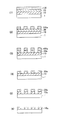
本発明者は、繰返し使用によって転写パターン幅の変化(CD変動)が生じた転写マスクにおける遷移金属とケイ素を含有するパターン形成用薄膜のパターンを調べた。その結果、図4に示すように、遷移金属とケイ素を含有する薄膜2(遷移金属シリサイド系膜、例えばMoSi系膜)の表層側にSiとO、若干の金属(例えばMo)を含む変質層2aが出来ていた。そして、これが転写パターン幅の変化(太り)Δdや、透過率及び位相シフト量の変化、の主な原因のひとつであることを解明した。
このような変質層が生じる理由(メカニズム)は次のように考えられる。すなわち、従来のスパッタ成膜された遷移金属シリサイド系薄膜2は構造的には隙間があり、成膜後にアニールしたとしても遷移金属シリサイド系薄膜2の構造の変化が小さい。このため、転写用マスクの使用過程においてこの隙間にたとえば大気中の酸素(O2)や水(H2O)等が入り込む。さらに、大気中の酸素(O2)がArFエキシマレーザーと反応することによって発生するオゾン(O3)等も前記隙間に入り込んで、遷移金属シリサイド系薄膜2を構成するSiや遷移金属M(例えばMo)と反応する。
Hereinafter, the present invention will be described in detail.
The inventor presumed the following factors that caused the deterioration of the transfer mask due to repeated use as the exposure light source wavelength became shorter.
The inventor examined the pattern of a thin film for pattern formation containing a transition metal and silicon in a transfer mask in which a transfer pattern width change (CD fluctuation) occurred due to repeated use. As a result, as shown in FIG. 4, an altered layer containing Si, O, and some metal (for example, Mo) on the surface layer side of the thin film 2 (transition metal silicide-based film, for example, MoSi-based film) containing transition metal and silicon. 2a was made. It was clarified that this is one of the main causes of the change (thickness) Δd in the transfer pattern width and the change in the transmittance and the phase shift amount.
The reason (mechanism) for generating such an altered layer is considered as follows. That is, there is a gap in the structure of the conventional transition metal silicide
つまり、このような環境で遷移金属シリサイド系薄膜2を構成するSiと遷移金属Mは、露光光(特にArFなどの短波長光)の照射を受けると励起され遷移状態となる。そして、Siが酸化し膨張する(SiよりもSiO2の体積が大きいため)と共に、遷移金属Mも酸化して遷移金属シリサイド系薄膜2の表層側に変質層2aが生成される。このとき、大気中の水分量(湿度)に応じて、生成されるSi酸化膜の品質は大きく異なり、湿度が高いほど密度の低いSi酸化膜が形成される。低密度Si酸化膜が形成される環境において、転写用マスクを繰返し使用する場合、露光光の照射を累積して受けると、Siの酸化及び膨張がさらに進行する。遷移金属シリサイド系薄膜2内の非変質層と変質層2aとの界面で酸化された遷移金属Mは、変質層中を拡散し、表面に析出して、例えば遷移金属Mの酸化物(例えばMoO3)となって昇華する。変質層2aの密度は更に低くなり、酸化しやすい状態になる。その結果、変質層2aの厚みが次第に大きくなる(遷移金属シリサイド系薄膜2中での変質層2aの占める割合が大きくなる)ものと考えられる。
That is, Si and the transition metal M constituting the transition metal silicide
このような変質層2aが発生し、さらに拡大していく現象は、遷移金属シリサイド系薄膜2を構成するSiや遷移金属Mの酸化反応のきっかけとなるこれらの構成原子が励起され遷移状態となるのに必要なエネルギーを有するArFエキシマレーザー等の波長200nm以下の露光光が長時間照射された場合に顕著に確認される。
以上のようなメカニズムによって、遷移金属シリサイド系のパターン形成用薄膜は、膜中のシリコン(Si)の酸化が原因と考えられる転写パターン幅の変化(CD太り)が発生する。
The phenomenon in which such a deteriorated layer 2a is generated and further expanded is that these constituent atoms that trigger the oxidation reaction of Si and transition metal M constituting the transition metal silicide-based
With the mechanism described above, the transition metal silicide-based pattern forming thin film undergoes a change in the transfer pattern width (CD thickening) that is considered to be caused by oxidation of silicon (Si) in the film.
本発明者は、遷移金属シリサイド系のパターン形成用薄膜の変質層が発生する要因について、さらに鋭意検討した。その結果、パターン形成用薄膜の上に積層されるクロム系材料からなる薄膜(エッチングマスク膜、遮光帯等の形成用の遮光膜等)の存在が変質層の発生に大きく影響していることが判明した。具体的には、まず、同じ膜構成の遷移金属シリサイド系のパターン形成用薄膜を有するが、クロム系薄膜がパターン形成用薄膜の上に積層されているマスクブランクと、積層されていないマスクブランクをそれぞれ準備した。次に、クロム系薄膜を備えたマスクブランクは、クロム系薄膜の転写パターンをマスクとして、パターン形成用薄膜をフッ素系ガスによるドライエッチングを行って転写パターンを形成した。その後、クロム系薄膜を塩素と酸素の混合ガスによるドライエッチングで除去し、従来の洗浄工程を行って、転写用マスクを作製した。一方、クロム系薄膜を備えていないマスクブランクは、レジストパターンをマスクとして、パターン形成用薄膜をフッ素系ガスによるドライエッチングを行って転写パターンを形成した。その後、レジストパターンを除去し、従来の洗浄工程を行って、転写用マスクを作製した。この2つの転写用マスクに対し、同一条件でArF露光光を長時間照射(積算照射量:40kJ/cm2,パルス周波数:300Hz)して検証を行った。その結果、クロム系薄膜を備えないマスクブランクから作製した転写用マスクの転写パターン幅の変化量(CD変動量)は、1nm程度で継続使用に問題のない変化量であった。これに対し、クロム系薄膜を備えたマスクブランクから作製した転写用マスクの転写パターン幅の変化量(CD変動量)は、15.9nmで継続使用にはかなり問題のある変化量であった。 The inventor of the present invention has further studied diligently the factors that cause the deteriorated layer of the transition metal silicide-based pattern forming thin film. As a result, the presence of a thin film (such as an etching mask film or a light shielding film for forming a light shielding band) made of a chromium-based material laminated on the pattern forming thin film greatly affects the generation of the altered layer. found. Specifically, first, a mask blank having a transition metal silicide pattern forming thin film having the same film configuration but having a chromium thin film laminated on the pattern forming thin film and an unstacked mask blank are provided. Prepared each. Next, the mask blank provided with the chromium-based thin film was formed by performing dry etching with a fluorine-based gas on the pattern forming thin film using the transfer pattern of the chromium-based thin film as a mask. Thereafter, the chromium-based thin film was removed by dry etching using a mixed gas of chlorine and oxygen, and a conventional cleaning process was performed to produce a transfer mask. On the other hand, for the mask blank not provided with the chromium-based thin film, a transfer pattern was formed by performing dry etching with a fluorine-based gas on the pattern forming thin film using the resist pattern as a mask. Thereafter, the resist pattern was removed, and a conventional cleaning process was performed to produce a transfer mask. The two transfer masks were verified by irradiating ArF exposure light under the same conditions for a long time (integrated dose: 40 kJ / cm 2 , pulse frequency: 300 Hz). As a result, the change amount (CD fluctuation amount) of the transfer pattern width of the transfer mask produced from the mask blank not provided with the chrome-based thin film was about 1 nm, and there was no problem in continuous use. On the other hand, the change amount (CD fluctuation amount) of the transfer pattern width of the transfer mask produced from the mask blank provided with the chromium-based thin film was 15.9 nm, which was a considerably problematic change amount for continuous use.
パターン幅の変化量の大きかった転写用マスクを同条件で再度作製し、ArF露光光の照射は行わずに、二次イオン質量分析法(SIMS:Secondary Ion Mass Spectrometry)を用い、試料を削りながら測定するダイナミックモード(D-SIMS)で、パターン形成用薄膜中のパターン形成用薄膜の成膜時の組成には含まれない物質、すなわち、転写用マスクの作製過程で付着(残留)した残留物質を調べた。その結果、パターン形成用薄膜のクロムと塩素の残留濃度が高いことが判明した。更に、残留物質がどの部位にどのように存在しているか調べるため、非パターンの領域(いわゆる「べた」の領域。転写パターンの側壁部分が存在しない領域)と、ラインアンドスペースを含む領域(転写パターンの側壁部分が存在する領域)について、ダイナミックモード(D-SIMS)で残留物質濃度を調べた。その結果、非パターンの領域(いわゆる「べた」の領域)では、表層で残留物質濃度が高く、深さ方向に向かって残留物質濃度が急激に減少していた。このことから、表層に残留物質(Cr)があることが判った(図2参照)。また、ラインアンドスペースを含む領域では、表層で残留物質濃度が高いことは同じであった。しかし、表層が削られた後も深さ方向に向かって残留物質濃度があまり減少しないことから、パターンの側壁部分にも残留物質(Cr)が高い濃度で存在することが判った(図2参照)。なお、図2のD-SIMSでは一次イオンはO2とした。 A transfer mask with a large change in pattern width was prepared again under the same conditions, and secondary ion mass spectrometry (SIMS) was used to scrape the sample without irradiating ArF exposure light. In the dynamic mode (D-SIMS) to be measured, the material that is not included in the composition of the patterning thin film in the patterning thin film, that is, the residual material that is attached (residual) during the process of making the transfer mask I investigated. As a result, it was found that the residual concentration of chromium and chlorine in the pattern forming thin film was high. Furthermore, in order to investigate how and where the residual material exists, a non-pattern region (a so-called “solid” region, a region where the side wall portion of the transfer pattern does not exist) and a region including a line and space (transfer) Residual material concentration was examined in dynamic mode (D-SIMS) for the region where the side wall of the pattern exists. As a result, in the non-pattern region (so-called “solid” region), the residual material concentration was high in the surface layer, and the residual material concentration was rapidly decreased in the depth direction. From this, it was found that there was a residual material (Cr) on the surface layer (see FIG. 2). Further, in the region including the line and space, it was the same that the residual substance concentration was high in the surface layer. However, since the residual substance concentration does not decrease much in the depth direction even after the surface layer is cut, it was found that the residual substance (Cr) is also present at a high concentration in the side wall portion of the pattern (see FIG. 2). ). Incidentally, the primary ions are D-SIMS in Figure 2 was O 2.
また、クロムの場合と同様に、塩素の残留濃度についてD-SIMSで測定したものを図3に示す。図3のD-SIMSでは一次イオンはCsとした。塩素の残留濃度による変質層への影響を確認するため、クロム系薄膜除去時のドライエッチング時間を長くして、意図的に転写パターン側壁の塩素残留濃度を増やし、同条件のArF露光光の照射を行ったところ、変質層の幅(CD変動量)との相関性は特にみられなかった。 Further, as in the case of chromium, FIG. 3 shows the residual concentration of chlorine measured by D-SIMS. In D-SIMS of FIG. 3, the primary ion is Cs. In order to confirm the influence of the residual chlorine concentration on the deteriorated layer, the dry etching time for removing the chromium-based thin film is lengthened, the residual chlorine concentration on the transfer pattern side wall is intentionally increased, and irradiation with ArF exposure light under the same conditions is performed. As a result, there was no particular correlation with the width of the deteriorated layer (CD fluctuation amount).
これらのD-SIMSの結果等により、マスクブランクの製造時には付着し得ない転写パターンの側壁部分、パターン形成用薄膜のクロム系薄膜と接する表層以外の部分のCrの残留物質濃度が高い濃度で存在することが判明した。これは、クロム系薄膜の転写パターンをマスクとし、パターン形成用薄膜をドライエッチングして転写パターンを形成後に行われるクロム系薄膜の除去時に、塩素と酸素の混合ガスによるドライエッチングで昇華したクロムがパターン形成用薄膜の転写パターン側壁に再付着し、遷移金属とケイ素の構造の隙間に入り込んだ、あるいはケイ素と結合したため、従来の洗浄工程では除去できなかったものと考えられる。 Due to these D-SIMS results, there is a high concentration of residual Cr in the side walls of the transfer pattern that cannot adhere to the mask blank when it is manufactured, and in the portions other than the surface layer in contact with the chromium-based thin film of the pattern forming thin film. Turned out to be. This is because the chromium-based thin film transfer pattern is used as a mask, and the chromium film sublimated by dry etching with a mixed gas of chlorine and oxygen is removed when the chromium-based thin film is removed after the pattern forming thin film is dry-etched to form the transfer pattern. It is considered that the film could not be removed by the conventional cleaning process because it reattached to the side wall of the pattern transfer thin film and entered the gap between the transition metal and silicon structures or bonded to silicon.
この作製された転写用マスクにArF露光光が照射された場合、パターン形成用薄膜の材料の遷移金属と同様、残留しているクロムもArF露光光によって励起されて遷移状態となり、残留している塩素、大気中の酸素やArF露光光との反応で発生したオゾンと反応して昇華する。パターン側壁部分から膜材料の遷移金属だけでなくクロムも昇華して抜けていくため、変質層中の隙間はより多くなり、パターン形成用薄膜内の非変質層と変質層との界面から遷移金属が昇華しやすい状態となる。このようなメカニズムにより、パターン側壁部分にクロムが多く残留していると変質層の成長が大きくなってしまうと本発明者らは解明した。そして、本発明者らは、これらの解明事実、考察に基づき、変質層の発生、拡大を抑える方策として上記のようにして生じたパターン形成用薄膜の転写パターン側壁部分のクロム残留物に着目し、さらに鋭意研究を続けた結果、本発明を完成したものである。 When ArF exposure light is irradiated to the produced transfer mask, the remaining chromium is excited by the ArF exposure light and remains in the transition state, as is the case with the transition metal of the pattern forming thin film material. It reacts with chlorine, ozone in the atmosphere, and ozone generated by reaction with ArF exposure light to sublimate. Since not only the transition metal of the film material but also chromium is sublimated and escapes from the pattern side wall, there are more gaps in the altered layer, and the transition metal from the interface between the unaltered layer and the altered layer in the pattern forming thin film. Will be in a state of being easily sublimated. By this mechanism, the present inventors have clarified that the growth of the deteriorated layer becomes large when a large amount of chromium remains on the side wall portion of the pattern. Based on these elucidated facts and considerations, the present inventors paid attention to the chromium residue on the side wall portion of the transfer pattern of the pattern forming thin film generated as described above as a measure for suppressing the generation and expansion of the deteriorated layer. As a result of further intensive studies, the present invention has been completed.
本発明の転写用マスクは、
透光性基板上に設けられたパターン形成用薄膜に転写パターンが形成されてなる転写用マスクにおいて、
前記転写用マスクは、波長200nm以下の露光光が適用されるものであり、
前記パターン形成用薄膜は、クロムを除く遷移金属およびケイ素を含有する材料からなり、
前記パターン形成用薄膜の膜中のクロム含有量が、1.0×10¹⁸atom/cm3未満であることを特徴とする(構成1)。
本発明において、前記パターン形成用薄膜は、DRAM hp45nm世代以降の転写パターンを有することを特徴とする(構成5)。
The transfer mask of the present invention is
In a transfer mask in which a transfer pattern is formed on a thin film for pattern formation provided on a translucent substrate,
The transfer mask is one to which exposure light having a wavelength of 200 nm or less is applied,
The pattern forming thin film is made of a material containing transition metal excluding chromium and silicon,
The chromium content in the pattern forming thin film is less than 1.0 × 10 18 atoms / cm 3 (Configuration 1).
In the present invention, the pattern forming thin film has a transfer pattern of DRAM hp 45 nm generation or later (Configuration 5).
本発明者は、前記のとおり、転写パターン用薄膜の転写パターン側壁部分のクロム残留物が変質層の成長に大きな影響を与えているという新たな知見を得た。クロムを除く遷移金属とケイ素を含有する転写パターン用薄膜の転写パターン側壁部分にクロム残留物を付着させない(クロム残留濃度を低減させる)という観点だけならば、クロム系薄膜をマスク(エッチングマスク)として転写パターン用薄膜に転写パターンを形成するマスクブランクの構成としないことが最も近道である。しかし、前記のとおり、転写パターンの微細化が進んでいる現状では、特に、DRAM hp45nm世代以降、特にhp32nm世代以降のバイナリ型の転写用マスクの場合、レジストパターンをマスクとしてパターン形成用薄膜に転写パターンを高い精度で形成することは困難である。 As described above, the present inventor has obtained a new finding that the chromium residue on the transfer pattern side wall portion of the transfer pattern thin film has a great influence on the growth of the deteriorated layer. From the standpoint of preventing chromium residue from adhering to the transfer pattern side wall of the transfer pattern thin film containing transition metals and silicon other than chromium (reducing chromium residual concentration), the chromium-based thin film is used as a mask (etching mask). The shortest way is not to use a mask blank that forms a transfer pattern on the transfer pattern thin film. However, as described above, in the current situation where the transfer pattern is becoming finer, in particular, in the case of a binary transfer mask of DRAM hp 45 nm generation or later, especially hp 32 nm generation or later, the resist pattern is used as a mask to transfer to the pattern forming thin film. It is difficult to form a pattern with high accuracy.
DRAM hp45nm世代のバイナリ型転写用マスクの場合、微細補助パターン(SRAF:Sub-Resolution Assist Feature)の幅は60nm程度と狭い幅であり、レジストパターンの倒壊・脱離がないようにするにはレジスト膜の膜厚は150nm以下とすることが必要である。この膜厚では、エッチングマスク膜なしに転写パターン用薄膜に転写パターンを形成することは難しい。さらに、DRAM hp32nm世代のバイナリ型転写用マスクの場合、SRAFの幅は40nm前後と非常に狭い幅であり、レジスト膜の膜厚は100nm以下とすることが必要である。もはやこの膜厚ではエッチングマスク膜なしに転写パターン用薄膜に転写パターンを形成することは困難である。 In the case of DRAM hp45nm generation binary transfer masks, the width of the fine auxiliary pattern (SRAF: Sub-Resolution Assist Feature) is as narrow as about 60nm. To prevent the resist pattern from collapsing and detaching, resist The film thickness must be 150 nm or less. With this film thickness, it is difficult to form a transfer pattern on a transfer pattern thin film without an etching mask film. Furthermore, in the case of a DRAM hp32 nm generation binary transfer mask, the SRAF has a very narrow width of around 40 nm, and the resist film thickness must be 100 nm or less. At this film thickness, it is difficult to form a transfer pattern on a transfer pattern thin film without an etching mask film.
一方、位相シフトマスクの場合、クロムを除く遷移金属とケイ素を含有するパターン形成用薄膜の上に遮光帯等を形成するために遮光膜を積層させる必要がある。エッチングマスク膜や遮光膜にクロム以外の材料を用いる方法も考えられる。しかし、クロムを除く遷移金属とケイ素を含有するパターン形成用薄膜に対して高いエッチング選択性を有すること、エッチングによる除去時にパターン形成用薄膜への影響が小さいこと等、これらの条件を確実に満たす信頼性の高い材料は、クロム系材料以外にはなかなか見当たらない状況である。 On the other hand, in the case of a phase shift mask, it is necessary to laminate a light shielding film in order to form a light shielding band or the like on a pattern forming thin film containing transition metal excluding chromium and silicon. A method using a material other than chromium for the etching mask film or the light shielding film is also conceivable. However, it satisfies these conditions, such as having high etching selectivity for patterning thin films containing transition metals other than chromium and silicon, and having little effect on patterning thin films when removed by etching. A highly reliable material is rarely found except for chromium-based materials.
本発明者は、クロムを除く遷移金属とケイ素を含有するパターン形成用薄膜の上に、クロム系薄膜を備えた構成のマスクブランクから転写用マスクを作製する場合、作製プロセス中にパターン形成用薄膜に付着してしまうクロムの含有量を洗浄工程等でどの程度まで減少させれば、ArF露光光を長時間照射(総照射量 40kJ/cm2)されても問題ないCD変動量に抑制されるか検討した。DRAM hp32nm世代では、ウェハ上でCD制御を2.6nm以下とする必要があり、この点を考慮すると、転写用マスクに求められるCD変動量は5nm以下とすることが望ましい。各種検証の結果、図1に示すように転写パターン用薄膜中のクロム含有量(Cr残留濃度)が1.0×10¹⁸atoms/cm3未満であれば、CD変動量を求められている5nm以下に抑制することができることを突き止めた。さらには、転写パターン用薄膜中のクロム含有量を5.0×1017atoms/cm3以下とすると、より確実にArF露光光照射によるCD変動量を抑制できることを突き止めた。
When the present inventor forms a transfer mask from a mask blank having a chromium-based thin film on a thin film for pattern formation containing transition metal excluding chromium and silicon, the thin film for pattern formation is produced during the production process. If the content of chromium adhering to the substrate is reduced to what extent by a cleaning process or the like, the CD fluctuation amount can be suppressed even if ArF exposure light is irradiated for a long time (
本発明において、パターン形成用薄膜は、転写パターン(マスクパターン)を形成するための薄膜である。
本発明において、パターン形成用薄膜は、遷移金属(クロムを除く)およびケイ素を含有する材料からなる膜を意図して形成した膜であり、実質的にクロムは含まれないことを意図して作製された膜である。例えば、スパッタリング法でパターン形成用薄膜を透光性基板上に形成する場合、クロムを含有しないスパッタターゲットを用い、成膜ガスにもクロムは含まれないものを使用したものである。
このため、パターン形成用薄膜からなる転写パターンの表層(クロム系薄膜に接する表面及び側壁部分)を除く膜中のクロム含有量は、1.0×10¹⁶atom/cm3以下のレベル(実質的にクロムは含まれないとされるレベル)である。
In the present invention, the pattern forming thin film is a thin film for forming a transfer pattern (mask pattern).
In the present invention, a thin film for pattern formation is a film formed with the intention of forming a film made of a material containing a transition metal (except chromium) and silicon, and is prepared with the intention of substantially not containing chromium. Film. For example, when a pattern forming thin film is formed on a light-transmitting substrate by sputtering, a sputtering target that does not contain chromium is used, and a film forming gas that does not contain chromium is used.
For this reason, the chromium content in the film excluding the surface layer (surface and side wall portions in contact with the chromium-based thin film) of the transfer pattern made of the pattern forming thin film is a level of 1.0 × 10 16 atoms / cm 3 or less (substantially Chrome is not included).
パターン形成用薄膜からなる転写パターンは、その表層のクロム含有量は、1.0×10¹⁸atom/cm3未満とする必要がある。特に、側壁部分は、転写用マスクの作製時のCr系薄膜の剥離時に露出している部分であり、ArF露光光の照射を直接受け、かつ大気に接しているという変質層が形成される条件が最も揃っている。この側壁部分については、クロム含有量は、1.0×1018atom/cm3未満とすることによる効果は顕著にあらわれる。 The transfer pattern made of the pattern forming thin film needs to have a chromium content of less than 1.0 × 10 18 atoms / cm 3 on the surface layer. In particular, the side wall portion is a portion that is exposed when the Cr-based thin film is peeled off at the time of manufacturing the transfer mask, and is subjected to irradiation with ArF exposure light and is in a condition that an altered layer is formed that is in contact with the atmosphere. Is the most complete. With respect to this side wall portion, the effect of making the chromium content less than 1.0 × 10 18 atoms / cm 3 is prominent.
なお、本発明でいうパターン形成用薄膜の転写パターン幅のCD変動量は、図4に示すように、転写パターン2の表層に生じる変質層2aの厚さをΔdとすると、2Δdで定義される。
図4(1)は孤立スペースやホールのようなスペース形状の場合で、CD変化量=a1−a2=2Δdである。
図4(2)は孤立ラインやドットのようなパターン形状の場合で、CD変化量=a4−a3=2Δdである。
なお、ラインアンドスペースパターンの場合は、どちらで定義されてもよい。
The CD variation amount of the transfer pattern width of the pattern forming thin film referred to in the present invention is defined as 2Δd, where Δd is the thickness of the altered layer 2a generated on the surface layer of the
FIG. 4A shows a case of a space shape such as an isolated space or a hole, and the CD variation amount = a1-a2 = 2Δd.
FIG. 4B shows a pattern shape such as an isolated line or a dot, and CD variation amount = a4-a3 = 2Δd.
In the case of a line and space pattern, it may be defined by either.
本発明において、クロムを除く遷移金属およびケイ素を含有する材料からなるパターン形成用薄膜における遷移金属(M)としては、モリブデン(Mo)、タンタル(Ta)、タングステン(W)、チタン(Ti)、ジルコニウム(Zr)、バナジウム(V)、ニオブ(Nb)、ニッケル(Ni)、パラジウム(Pb)、ルテニウム(Ru)、ロジウム(Rh)、ハフニウム(Hf)の何れか一つ又は合金、などが挙げられる。
本発明において、パターン形成用薄膜は、遷移金属とケイ素の他に、窒素、酸素、炭素、水素、不活性ガス(ヘリウム,アルゴン,キセノン等)等を含有する材料が含まれる。
In the present invention, the transition metal (M) in the thin film for pattern formation comprising a transition metal excluding chromium and a material containing silicon includes molybdenum (Mo), tantalum (Ta), tungsten (W), titanium (Ti), Zirconium (Zr), vanadium (V), niobium (Nb), nickel (Ni), palladium (Pb), ruthenium (Ru), rhodium (Rh), hafnium (Hf), or an alloy, etc. It is done.
In the present invention, the thin film for pattern formation includes materials containing nitrogen, oxygen, carbon, hydrogen, inert gas (helium, argon, xenon, etc.), etc. in addition to the transition metal and silicon.
本発明において、パターン形成用薄膜は、バイナリ型マスクにおける遮光膜、又は、ハーフトーン型位相シフト膜とすることができる。また、パターン形成用薄膜は、パターン転写を行う転写対象物のレジスト膜が感光されない程度の所定の透過率で露光光を透過させる薄膜であるが、薄膜を透過した露光光に、薄膜のない部分を透過した露光光との間で位相差を生じないように調整されている光半透過膜とすることもできる。このタイプの光半透過膜が適用されたマスクブランクは、エンハンサマスクを作製する際に使用されることが多い。この光半透過膜の場合においても、露光光に対して所定の透過率を有しているため、露光装置での転写対象物のレジスト膜への露光時に重ね露光を行うと、レジスト膜が感光してしまう場合がある。このため、光半透過膜の上に遮光帯を形成するための遮光膜を積層させた膜構成とする場合が多い。 In the present invention, the thin film for pattern formation can be a light shielding film in a binary mask or a halftone phase shift film. The thin film for pattern formation is a thin film that transmits exposure light at a predetermined transmittance such that the resist film of the transfer object to be transferred is not exposed to light. It is also possible to use a light semi-transmissive film that is adjusted so as not to cause a phase difference with respect to the exposure light that has passed through. A mask blank to which this type of translucent film is applied is often used when an enhancer mask is manufactured. Even in the case of this light semi-transmissive film, the resist film has a predetermined transmittance with respect to the exposure light. Therefore, when the exposure is performed on the resist film of the transfer object in the exposure apparatus, the resist film is exposed to light. May end up. For this reason, in many cases, a film configuration is formed in which a light shielding film for forming a light shielding band is laminated on the light semi-transmissive film.
本発明において、前記パターン形成用薄膜中の遷移金属は、モリブデンである態様が含まれる(構成2)。
前記の通り、モリブデンは酸素やオゾンと結合(MoO3)となりやすく、MoO3は気化物質であるため、パターン側壁部分の変質層を抑制する本願発明が特に有効に機能するからである。
In the present invention, the transition metal in the pattern forming thin film includes molybdenum (Configuration 2).
As described above, molybdenum is easily combined with oxygen and ozone (MoO 3 ), and MoO 3 is a vaporized substance. Therefore, the present invention that suppresses the altered layer on the pattern side wall portion functions particularly effectively.
本発明において、前記パターン形成用薄膜は、光学濃度2.5以上を有する遮光膜である態様が含まれる(構成3)。
バイナリ型マスクの場合、シングル露光に対応するためには、パターン転写領域における遮光膜の光学濃度は最低でも2.5以上とする必要があるからである。露光装置の構造や転写パターンを転写するウェハ上のレジスト膜等の感度特性等にもよっては、遮光膜により高い遮光性能が求められるため、光学濃度2.8以上であるとより好ましく、3.0以上であると種々のマスク使用環境に対応可能である。
In the present invention, the pattern forming thin film includes a mode of being a light shielding film having an optical density of 2.5 or more (Configuration 3).
This is because in the case of a binary mask, the optical density of the light-shielding film in the pattern transfer region needs to be at least 2.5 or more in order to support single exposure. Depending on the structure of the exposure apparatus and the sensitivity characteristics of the resist film or the like on the wafer to which the transfer pattern is transferred, a high light shielding performance is required for the light shielding film, so that the optical density is more preferably 2.8 or more. If it is 0 or more, it is possible to cope with various mask use environments.
本発明において、
前記パターン形成用薄膜は、透光性基板側から遮光層および表面反射防止層の少なくとも2層以上の積層構造からなる遮光膜である態様が含まれる(構成4)。
遮光膜が、遮光層と表面反射防止層の2層積層構造からなる場合、遮光層に裏面反射(透光性基板と遮光層との界面における露光光の反射)の防止機能を持たせる必要がある。
さらに、遮光膜は、遮光層の透光性基板側に裏面反射防止層も設けた3層積層構造としてもよい。この場合、裏面反射防止層が裏面反射防止機能を有するため、遮光層は光学濃度を確保することを重視した膜設計をすることができる。なお、遮光膜は、単層の組成傾斜膜としてもよく、表面反射防止膜、遮光層、裏面反射防止膜についても組成傾斜膜としてもよい。
In the present invention,
The thin film for pattern formation includes an embodiment in which the thin film for pattern formation is a light shielding film having a laminated structure of at least two layers of a light shielding layer and a surface antireflection layer from the translucent substrate side (Configuration 4).
When the light-shielding film has a two-layer laminated structure of the light-shielding layer and the front-surface antireflection layer, the light-shielding layer needs to have a function of preventing back surface reflection (reflection of exposure light at the interface between the light-transmitting substrate and the light-shielding layer). is there.
Further, the light shielding film may have a three-layer structure in which a back surface antireflection layer is also provided on the light transmissive substrate side of the light shielding layer. In this case, since the back surface antireflection layer has a back surface antireflection function, the light shielding layer can be designed with a focus on ensuring optical density. The light shielding film may be a single-layer composition gradient film, and the surface antireflection film, the light shielding layer, and the back surface antireflection film may also be composition gradient films.
本発明において、前記パターン形成用薄膜は、ハーフトーン型位相シフト膜である態様が含まれる(構成6)。 In the present invention, the pattern forming thin film includes a mode in which the thin film is a halftone phase shift film (Configuration 6).
本発明において、ハーフトーン型位相シフト膜(光半透過膜)は、単層構造、低透過率層と高透過率層とからなる2層構造、多層構造を含む。
ハーフトーン型位相シフト膜は、高透過率タイプを含む。高透過率タイプは、例えば、通常の透過率1〜10%未満に対し、相対的に高い透過率10〜30%を有するものをいう。
In the present invention, the halftone phase shift film (light semi-transmissive film) includes a single layer structure, a two-layer structure composed of a low transmittance layer and a high transmittance layer, and a multilayer structure.
The halftone phase shift film includes a high transmittance type. The high transmittance type means, for example, a material having a relatively high transmittance of 10 to 30% with respect to a normal transmittance of less than 1 to 10%.
本発明の転写用マスクの製造方法は、
透光性基板上に、クロムを除く遷移金属およびケイ素を含有する材料からなるパターン形成用薄膜と、クロムを含有する材料からなるクロム系薄膜が順に積層したマスクブランクを用いた転写用マスクの製造方法において、
前記転写用マスクは、波長200nm以下の露光光が適用されるものであり、
クロム系薄膜上に、転写パターンを有するレジスト膜を形成する工程と、
転写パターンを有するレジスト膜をマスクとして、クロム系薄膜に転写パターンを形成する工程と、
転写パターンを有するクロム系薄膜をマスクとして、パターン形成用薄膜に転写パターンを形成する工程と、
前記クロム系薄膜をエッチングによって除去する工程と、
をこの順に行って転写用マスクを作製し、
作製した転写用マスクに対し、前記パターン形成用薄膜からなる転写パターンのクロム含有量が1.0×10¹⁸atoms/cm3未満になるまで、アルカリ溶液洗浄、温水洗浄、オゾン含有水洗浄のうち1以上の洗浄を行う洗浄工程を有することを特徴とする(構成7)。
本発明において、前記パターン形成用薄膜は、DRAM hp45nm世代以降の転写パターンを有することを特徴とする(構成13)。
The method for producing the transfer mask of the present invention comprises:
Production of a transfer mask using a mask blank in which a pattern forming thin film made of a material containing silicon and a transition metal excluding chromium and a chromium-based thin film made of a material containing chromium are sequentially laminated on a translucent substrate In the method
The transfer mask is one to which exposure light having a wavelength of 200 nm or less is applied,
Forming a resist film having a transfer pattern on the chromium-based thin film;
Using the resist film having the transfer pattern as a mask, forming a transfer pattern on the chromium-based thin film,
Using a chromium-based thin film having a transfer pattern as a mask, forming a transfer pattern on the pattern forming thin film; and
Removing the chromium-based thin film by etching;
In this order to make a transfer mask,
Of the produced transfer mask, the alkali transfer cleaning, the hot water cleaning, and the ozone-containing water cleaning are performed until the chromium content of the transfer pattern made of the pattern forming thin film is less than 1.0 × 10 18 atoms / cm 3. It has the washing | cleaning process which performs 1 or more washing | cleaning (Structure 7).
In the present invention, the thin film for pattern formation has a transfer pattern of DRAM hp 45 nm generation or later (Configuration 13).
本発明者は、従来行われているような洗浄工程では、パターン側壁部分のクロム残留濃度を低減させることは容易ではないことを考慮した結果、特定の洗浄工程でクロム残留濃度の高いパターン側壁部分自体を溶解除去することで変質層の成長を抑制できるという結論に至った。 As a result of considering that it is not easy to reduce the residual chromium concentration in the pattern side wall in the cleaning process as conventionally performed, the present inventor has found that the pattern side wall in the specific cleaning process has a high residual chromium concentration. It came to the conclusion that the growth of the altered layer can be suppressed by dissolving and removing itself.
本発明者らは、Cr系膜のパターンをマスクとして使用し、パターン形成用薄膜(例えばMoSi系バイナリ膜)をSF6とHeの混合ガスによるドライエッチングによってパターニングした後、エッチングマスクとして使用したCr系膜のパターンをドライエッチング(塩素と酸素のプラズマ)によって剥離除去した後の最初の洗浄が、ArF照射耐性に大きな影響を与えており、重要であることを解明した。
本発明者は、最初の洗浄が適切でないと、以後の工程で種々の洗浄を施しても改善しない傾向にあることを突き止めた。例えば、最初の洗浄が、硫酸過水、熱濃硫酸などの酸洗浄であると、以後の工程で種々の洗浄を施しても改善しない傾向にある。
本発明者は、前記最初の洗浄として、アルカリ溶液洗浄、温水洗浄、オゾン含有水洗浄のうち1以上の洗浄を行う洗浄工程が適していることを突き止めた。これらの洗浄工程は、上述したクロム残留濃度の高いパターン側壁部分を溶解し、かつ溶解したクロムが再度転写パターンの内部に侵入することなく除去でき、パターン形成用薄膜のクロム残留濃度を1.0×10¹⁸atoms/cm3未満とすることができることを突き止めた。さらに、これらの洗浄工程は、上記酸洗浄工程の如く、以後の工程で種々の洗浄を施しても改善しない傾向を示すことがない。
本発明者は、前記最初の洗浄として、アルカリ溶液洗浄、温水洗浄、オゾン含有水洗浄のうち1以上の洗浄を行う洗浄工程を適用することによって、上述したパターン形成用薄膜のクロム残留濃度(クロム含有量)を1.0×10¹⁸atoms/cm3未満まで低減することが可能であることを見い出した。また、アルカリ溶液洗浄、温水洗浄、オゾン含有水洗浄の洗浄順序や、洗浄時間を調整することで、転写パターン用薄膜中のクロム含有量を5.0×1017atoms/cm3以下とすることも可能であり、より確実にArF露光光照射によるCD変動量を抑制できる。
The inventors of the present invention used a Cr-based film pattern as a mask, patterned a thin film for pattern formation (for example, a MoSi-based binary film) by dry etching with a mixed gas of SF 6 and He, and then used Cr as an etching mask. It was clarified that the first cleaning after removing and removing the pattern of the system film by dry etching (chlorine and oxygen plasma) has a great influence on the ArF irradiation resistance and is important.
The present inventor has found that if the initial cleaning is not appropriate, it does not tend to improve even if various cleanings are performed in the subsequent steps. For example, if the first cleaning is an acid cleaning such as sulfuric acid / hydrogen peroxide or hot concentrated sulfuric acid, there is a tendency that even if various cleanings are performed in the subsequent steps, it does not improve.
The present inventor has found that a cleaning process in which at least one cleaning is performed among the alkaline solution cleaning, the warm water cleaning, and the ozone-containing water cleaning is suitable as the first cleaning. These cleaning steps dissolve the above-described pattern side wall portion having a high chromium residual concentration and can remove the dissolved chromium without entering the inside of the transfer pattern again. The residual chromium concentration of the pattern forming thin film is 1.0. It was found that it can be less than × 10 18 atoms / cm 3 . Further, these washing steps do not show a tendency not to improve even if various washings are performed in the subsequent steps, like the acid washing step.
The present inventor applied a cleaning step of performing at least one of alkaline solution cleaning, warm water cleaning, and ozone-containing water cleaning as the first cleaning, thereby providing the above-described residual chromium concentration (chrome) in the pattern forming thin film. It has been found that the (content) can be reduced to less than 1.0 × 10 18 atoms / cm 3 . In addition, the chromium content in the transfer pattern thin film should be 5.0 × 10 17 atoms / cm 3 or less by adjusting the cleaning sequence and cleaning time of alkaline solution cleaning, warm water cleaning, and ozone-containing water cleaning. It is also possible to suppress the CD fluctuation amount due to ArF exposure light irradiation more reliably.
なお、本発明者は、各種検証の結果、転写パターン用薄膜の転写パターンの幅が4nm減少するまで、あるいは、転写パターンのスペース幅が4nm増加するまで、洗浄工程を行うことで、パターン形成用薄膜のクロム残留濃度(クロム含有量)を1.0×10¹⁸atoms/cm3未満に低減できることを突き止めている。 In addition, as a result of various verifications, the present inventor performs the cleaning process until the transfer pattern width of the transfer pattern thin film decreases by 4 nm or the transfer pattern space width increases by 4 nm. It has been found that the residual chromium concentration (chromium content) of the thin film can be reduced to less than 1.0 × 10 18 atoms / cm 3 .
アルカリ溶液で洗浄する工程は、アンモニアと過酸化水素を含有する水溶液などのアルカリ溶液を用いることが好ましい。
アルカリ溶液の温度は、15〜80℃程度が好ましい。
アルカリ溶液による処理時間は、10〜20分程度が好ましい。
温水で洗浄する工程は、イオン交換水(DI water:deionized water)などの純水や超純水を用いることが好ましい。
温水の温度は、70〜90℃程度が好ましい。
温水による処理時間は、10〜20分程度が好ましい。
オゾン含有水で洗浄する工程は、40〜60ppmのオゾン含有水を用いることが好ましい。
オゾン含有水の温度は、15〜30℃程度が好ましい。
オゾン含有水による処理時間は、10〜20分程度が好ましい。
The step of washing with an alkaline solution preferably uses an alkaline solution such as an aqueous solution containing ammonia and hydrogen peroxide.
The temperature of the alkaline solution is preferably about 15 to 80 ° C.
The treatment time with the alkaline solution is preferably about 10 to 20 minutes.
In the step of washing with warm water, it is preferable to use pure water such as ion-exchanged water (DI water: deionized water) or ultrapure water.
The temperature of the hot water is preferably about 70 to 90 ° C.
The treatment time with warm water is preferably about 10 to 20 minutes.
The step of cleaning with ozone-containing water preferably uses 40 to 60 ppm of ozone-containing water.
The temperature of the ozone-containing water is preferably about 15 to 30 ° C.
The treatment time with ozone-containing water is preferably about 10 to 20 minutes.
本発明において、前記洗浄工程は、アルカリ溶液洗浄、温水洗浄、およびオゾン含有水洗浄をこの順に行うことが好ましい(構成8)。
本発明者は、前記洗浄工程は、アルカリ溶液洗浄、温水洗浄、およびオゾン含有水洗浄をこの順に行うことによって、パターン形成用薄膜のクロム含有量を1.0×10¹⁸atoms/cm3未満、さらには5.0×1017atoms/cm3以下にまで、効率よく低減することができることを見い出した。
In this invention, it is preferable that the said washing | cleaning process performs alkali solution washing | cleaning, warm water washing | cleaning, and ozone containing water washing | cleaning in this order (Structure 8).
The inventor performs the cleaning step by performing alkaline solution cleaning, warm water cleaning, and ozone-containing water cleaning in this order, thereby reducing the chromium content of the pattern forming thin film to less than 1.0 × 10 18 atoms / cm 3 , Furthermore, it has been found that it can be efficiently reduced to 5.0 × 10 17 atoms / cm 3 or less.
本発明において、前記アルカリ溶液は、アンモニアと過酸化水素を含有する水溶液であることが好ましい(構成9)。
本発明者は、前記アルカリ溶液は、アンモニアと過酸化水素を含有する水溶液であることによって、上述したCr残渣を、非常に効率よくかつ確実に低減することができることを見い出した。
アンモニアと過酸化水素を含有する水溶液は、例えば、水酸化アンモニウム(NH4OH 濃度 25wt%):過酸化水素(H2O2 濃度 30wt%):水(H2O)=2:1:4(体積比)の溶液を用いることが好ましい。
In the present invention, the alkaline solution is preferably an aqueous solution containing ammonia and hydrogen peroxide (Configuration 9).
The present inventor has found that the above-mentioned Cr residue can be reduced very efficiently and reliably by the alkaline solution being an aqueous solution containing ammonia and hydrogen peroxide.
The aqueous solution containing ammonia and hydrogen peroxide is, for example, ammonium hydroxide (NH 4 OH concentration 25 wt%): hydrogen peroxide (H 2 O 2 concentration 30 wt%): water (H 2 O) = 2: 1: 4. It is preferable to use a (volume ratio) solution.
本発明の製造方法において、前記パターン形成用薄膜中の遷移金属は、モリブデンである態様が含まれる(構成10)。
前記の通り、モリブデンは酸素やオゾンと結合(MoO3)となりやすく、MoO3は気化物質であるため、パターン側壁部分の変質層を抑制する本願発明が特に有効に機能するからである。
In the production method of the present invention, an embodiment in which the transition metal in the pattern forming thin film is molybdenum is included (Configuration 10).
As described above, molybdenum is easily combined with oxygen and ozone (MoO 3 ), and MoO 3 is a vaporized substance. Therefore, the present invention that suppresses the altered layer on the pattern side wall portion functions particularly effectively.
本発明の製造方法において、前記パターン形成用薄膜は、光学濃度2.5以上を有する遮光膜であり、
前記クロム系薄膜は、エッチングによって除去する工程で全て除去される態様が含まれる(構成11)。
この場合、クロム系薄膜は、エッチングマスクとして使用され、使用後は全て除去され、この転写用マスクはバイナリ型マスクとして使用される。
バイナリ型マスクの場合、ダブル露光に対応するためには、パターン転写領域における遮光膜の光学濃度は最低でも2.5以上とする必要があるが、上記構成11によるとこの要件を満たすことができる。露光装置の構造や転写パターンを転写するウェハ上のレジスト膜等の感度特性等によっては、遮光膜により高い遮光性能が求められるため、光学濃度2.8以上であるとより好ましく、3.0以上であると種々のマスク使用環境に対応可能である。
In the manufacturing method of the present invention, the pattern forming thin film is a light shielding film having an optical density of 2.5 or more,
The aspect in which the chromium-based thin film is completely removed in the step of removing by etching is included (Configuration 11).
In this case, the chromium-based thin film is used as an etching mask and is completely removed after use, and this transfer mask is used as a binary mask.
In the case of a binary mask, the optical density of the light-shielding film in the pattern transfer region needs to be at least 2.5 in order to cope with double exposure. However, according to the above configuration 11, this requirement can be satisfied. . Depending on the structure of the exposure apparatus and the sensitivity characteristics of the resist film or the like on the wafer to which the transfer pattern is transferred, the light shielding film requires a high light shielding performance. Therefore, the optical density is preferably 2.8 or more, more preferably 3.0 or more. If it is, it can respond to various mask use environments.
転写用マスクを露光装置のマスクステージに設置し、ウェハ上のレジスト膜等にArF露光光で転写パターンを露光する際、ArF露光光は、透光性基板側から照射されて転写パターンが形成される領域のパターン形成用薄膜のないスペース部から透過して縮小光学系に出射される。このため、遮光パッチ等を設ける必要のないバイナリ型マスクの場合、少なくとも転写パターンが形成される領域は、クロム系薄膜が除去されていることが好ましく、パターン形成用薄膜の表面全体からクロム系薄膜が除去されていることが最も望ましい。 When the transfer mask is placed on the mask stage of the exposure apparatus and the transfer pattern is exposed to the resist film on the wafer with ArF exposure light, the ArF exposure light is irradiated from the translucent substrate side to form the transfer pattern. Then, the light is transmitted through a space portion without a pattern forming thin film in the region to be emitted to the reduction optical system. For this reason, in the case of a binary mask that does not require the provision of a light-shielding patch or the like, it is preferable that the chrome-based thin film is removed at least in the region where the transfer pattern is formed, and the chrome-based thin film is removed from the entire surface of the pattern forming thin film. Most preferably, is removed.
本発明において、
前記パターン形成用薄膜は、透光性基板側から遮光層および表面反射防止層の少なくとも2層以上の積層構造からなる遮光膜である態様が含まれる(構成12)。
In the present invention,
The pattern forming thin film includes a mode in which the thin film for pattern formation is a light shielding film having a laminated structure of at least two layers of a light shielding layer and a surface antireflection layer from the translucent substrate side (Configuration 12).
本発明の製造方法において、前記パターン形成用薄膜は、ハーフトーン型位相シフト膜であり、
前記クロム系薄膜とパターン形成用薄膜との積層構造で光学濃度2.5以上を有し、
前記クロム系薄膜をエッチングによって除去する工程で、転写パターン領域外周の遮光帯領域以外の領域の前記クロム系薄膜は除去されて遮光帯が形成される態様が含まれる(構成14)。
この場合、クロム系薄膜は、エッチングマスクとしての機能に加え、遮光帯領域における遮光性(光学濃度)を付与する機能を有する。
ハーフトーン型位相シフトマスクの場合、遮光帯領域の光学濃度は最低でも2.5以上とする必要があるが、上記構成14によるとこの要件を満たすことができる。なお、転写パターン領域内のハーフトーン型位相シフト膜に、大きな膜パターンであって遮光パッチが必要な部分については、クロム系薄膜を残してもよい。
In the manufacturing method of the present invention, the pattern forming thin film is a halftone phase shift film,
An optical density of 2.5 or more in a laminated structure of the chromium-based thin film and the pattern forming thin film;
The process of removing the chromium-based thin film by etching includes a mode in which the light-shielding band is formed by removing the chromium-based thin film in an area other than the light-shielding band area on the outer periphery of the transfer pattern area (Configuration 14).
In this case, the chromium-based thin film has a function of imparting a light shielding property (optical density) in the light shielding zone region in addition to the function as an etching mask.
In the case of the halftone phase shift mask, the optical density of the light shielding zone region needs to be at least 2.5 or more, but according to the configuration 14, this requirement can be satisfied. It should be noted that a chromium-based thin film may be left on the halftone phase shift film in the transfer pattern region for a portion having a large film pattern and requiring a light shielding patch.
本発明において、遮光膜における遮光層は、遮光性が非常に高い材料が好ましく、クロムに比べ遮光性が高い材料で構成することが好ましい。遷移金属とケイ素を含有する材料は、クロムに比べて遮光性が高い。
遷移金属のモリブデンとケイ素を含有する材料の光学濃度は、モリブデンの含有量[原子%]をモリブデンとケイ素の合計含有量[原子%]で除して百分率で表した比率(以下、(Mo/Mo+Si)比率という。)が、所定比率で頭打ちとなる傾向がある。材料中の他の元素(窒素等)の含有量によって、頭打ちとなる(Mo/Mo+Si)比率は多少変わるが40%より大きくはならない。モリブデンとケイ素を含有する材料は、モリブデンの含有量が高いと、耐薬性や耐洗浄性(特に、アルカリ洗浄や温水洗浄)が低下するという問題がある。これらのことを考慮すると、転写用マスクとして使用する際の必要最低限の耐薬性、耐洗浄性を確保できる(Mo/Mo+Si)比率である40%をモリブデンとケイ素を含有する遮光層として適用可能な上限とすることが好ましい。
In the present invention, the light shielding layer in the light shielding film is preferably made of a material having a very high light shielding property, and is preferably composed of a material having a light shielding property higher than that of chromium. A material containing a transition metal and silicon has higher light shielding properties than chromium.
The optical density of the material containing the transition metals molybdenum and silicon is determined by dividing the molybdenum content [atomic%] by the total content of molybdenum and silicon [atomic%] (hereinafter referred to as (Mo / Mo + Si) ratio)) tends to peak at a predetermined ratio. Depending on the content of other elements (such as nitrogen) in the material, the ratio of reaching the peak (Mo / Mo + Si) will vary slightly, but not more than 40%. A material containing molybdenum and silicon has a problem that when the content of molybdenum is high, chemical resistance and cleaning resistance (particularly alkali cleaning and hot water cleaning) decrease. Considering these, 40%, which is a (Mo / Mo + Si) ratio that can ensure the minimum chemical resistance and cleaning resistance when used as a transfer mask, can be applied as a light shielding layer containing molybdenum and silicon. It is preferable to set the upper limit.
一方、(Mo/Mo+Si)比率の下限については、遮光層中の他の元素の含有量によって光学濃度が変わるため、2層積層構造と3層積層構造の遮光膜では異なる。
裏面反射防止層、遮光層、表面反射防止層の3層積層構造の遮光膜の場合、遮光層に裏面および表面の反射防止機能を持たせる必要がないため、酸素や窒素を実質的に含有させなくてもよくなる。この場合においては、(Mo/Mo+Si)比率の下限が9%であっても薄い膜厚(60nm以下)でも遮光膜としての光学濃度2.5以上を十分に確保することができる。
他方、遮光層、表面反射防止層の2層積層構造の遮光膜の場合、遮光層に裏面反射防止機能を持たせる必要があるため、膜中の窒素含有量を30原子%以下の範囲で含有させる必要がある。この場合においては、(Mo/Mo+Si)比率の下限を15%とすることで、遮光膜としての光学濃度2.5以上を十分に確保することができる。
On the other hand, the lower limit of the (Mo / Mo + Si) ratio differs between the light-shielding films of the two-layer laminated structure and the three-layer laminated structure because the optical density varies depending on the content of other elements in the light-shielding layer.
In the case of a light-shielding film having a three-layer structure comprising a back-surface antireflection layer, a light-shielding layer, and a front-surface antireflection layer, the light-shielding layer does not need to have an anti-reflection function on the back and front surfaces. You do n’t have to. In this case, even if the lower limit of the (Mo / Mo + Si) ratio is 9%, an optical density of 2.5 or more as a light shielding film can be sufficiently secured even with a thin film thickness (60 nm or less).
On the other hand, in the case of a light-shielding film having a two-layer structure of a light-shielding layer and a front-surface antireflection layer, the light-shielding layer needs to have a back-surface antireflection function, so the nitrogen content in the film is within a range of 30 atomic% or less. It is necessary to let In this case, by setting the lower limit of the (Mo / Mo + Si) ratio to 15%, it is possible to sufficiently secure an optical density of 2.5 or more as the light shielding film.
なお、遮光膜の材料にモリブデン以外の遷移金属を適用した場合についても概ね同様の傾向を示す。また、酸素は、遮光層中の含有量に対する遮光性能の低下度合が窒素に比べて著しく大きく、酸素の含有率に比例して遮光層に必要な膜厚がより厚くなってしまう。窒素だけでも露光光に対する裏面反射率を低減させることは可能であることから、遮光層の酸素の含有量は、10原子%未満であることが好ましく、さらに好ましくは、酸素を実質的に含有しない(コンタミ等によって含有されることを許容する程度)ことが好ましい。 A similar tendency is generally exhibited when a transition metal other than molybdenum is applied as the material of the light shielding film. In addition, the degree of reduction in the light shielding performance with respect to the content in the light shielding layer is significantly larger than that of nitrogen, and the film thickness necessary for the light shielding layer is increased in proportion to the oxygen content. Since the back surface reflectance with respect to exposure light can be reduced with nitrogen alone, the content of oxygen in the light shielding layer is preferably less than 10 atomic%, and more preferably substantially free of oxygen. It is preferable (to the extent that it is allowed to be contained by contamination or the like).
本発明において、遮光膜における表面反射防止層は、遷移金属とケイ素に、さらに酸素および窒素から選ばれる少なくとも1つ以上の元素を含む材料を主成分とすることが好ましい。
具体的には、表面反射防止層は、遷移金属(M)とケイ素を主成分とする材料(MSiO,MSiN,MSiON,MSiOC,MSiCN,MSiOCN等)が好ましい。これらのうちでも、耐薬品性、耐熱性の観点からはMSiO、MSiONが好ましく、マスクブランクの欠陥品質の観点からMSiONが好ましい。
In the present invention, it is preferable that the surface antireflection layer in the light shielding film is mainly composed of a material containing at least one element selected from oxygen and nitrogen in addition to transition metal and silicon.
Specifically, the surface antireflection layer is preferably made of a material mainly composed of a transition metal (M) and silicon (such as MSiO, MSiN, MSiON, MSiOC, MSiCN, and MSiOCN). Among these, MSiO and MSiON are preferable from the viewpoint of chemical resistance and heat resistance, and MSiON is preferable from the viewpoint of the defect quality of the mask blank.
本発明において、表面反射防止層にMoSiON、MoSiO、MoSiN、MoSiOC、MoSiOCNを適用する場合、Moを多くすると耐洗浄性、特にアルカリ(アンモニア水等)や温水に対する耐性が小さくなる。この観点からは、表面反射防止層であるMoSiON、MoSiO、MoSiN、MoSiOC、MoSiOCN等では、Mo極力減らすことが好ましい。
また、応力制御を目的として高温で加熱処理(アニール)する際、Moの含有率が高いと膜の表面が白く曇る(白濁する)現象が生じることがわかった。これは、MoOが表面に析出するためであると考えられる。このような現象を避ける観点からは、表面反射防止層であるMoSiON、MoSiO、MoSiN、MoSiOC、MoSiOCN等では、表面反射防止層中のMoの含有率は10原子%未満であることが好ましい。しかし、Mo含有率が少なすぎる場合、DCスパッタリングの際の異常放電が顕著になり、欠陥発生頻度が高まる。よって、Moは正常にスパッタできる範囲で含有していることが望ましい。他の成膜技術によってはMoを含有せずに成膜可能な場合がある。
In the present invention, when MoSiON, MoSiO, MoSiN, MoSiOC, or MoSiOCN is applied to the surface antireflection layer, the cleaning resistance, particularly resistance to alkali (ammonia water or the like) or hot water is reduced when Mo is increased. From this point of view, MoSiON, MoSiO, MoSiN, MoSiOC, MoSiOCN, and the like, which are surface antireflection layers, are preferably reduced as much as possible.
Further, it was found that when heat treatment (annealing) was performed at a high temperature for the purpose of stress control, a high Mo content causes a phenomenon that the surface of the film becomes clouded white (clouded). This is considered to be because MoO precipitates on the surface. From the viewpoint of avoiding such a phenomenon, in the MoSiON, MoSiO, MoSiN, MoSiOC, MoSiOCN, etc., which are the surface antireflection layers, the Mo content in the surface antireflection layer is preferably less than 10 atomic%. However, when the Mo content is too low, abnormal discharge during DC sputtering becomes significant, and the frequency of occurrence of defects increases. Therefore, it is desirable that Mo is contained within a range where it can be sputtered normally. Depending on other film formation techniques, film formation may be possible without containing Mo.
遮光膜のArF露光光に対する表面反射率としては、30%以下を確保する必要性が高く、25%以下であると好ましく、遮光膜全体の膜厚が許容範囲内であれば20%以下が確保できると最も好ましい。
また、表面反射率を所定値以下に抑制するためには、表面反射防止層12の膜厚は5nmよりも大きいことが望ましい。また、より低反射率とするには、膜厚を7nm以上とすることが望ましい。さらに、生産安定性の観点や、転写用マスクを作製した後のマスク洗浄の繰り返しによる表面反射防止層の膜減りを考慮すると、表面反射防止層の膜厚は10nm以上あると好ましい。遮光膜全体での薄膜化を考慮すると、遮光膜の光学濃度への寄与度の低い表面反射防止層の膜厚は、20nm以下であることが望ましく、15nm以下であるとより望ましい。
As the surface reflectance of the light shielding film with respect to ArF exposure light, it is highly necessary to ensure 30% or less, preferably 25% or less. If the film thickness of the entire light shielding film is within an allowable range, 20% or less is secured. Most preferred if possible.
In order to suppress the surface reflectance below a predetermined value, the thickness of the surface antireflection layer 12 is desirably larger than 5 nm. In order to obtain a lower reflectance, the film thickness is desirably 7 nm or more. Furthermore, considering the production stability and the reduction in the thickness of the surface antireflection layer due to repeated mask cleaning after producing the transfer mask, the thickness of the surface antireflection layer is preferably 10 nm or more. In consideration of thinning of the entire light shielding film, the thickness of the surface antireflection layer having a low contribution to the optical density of the light shielding film is preferably 20 nm or less, and more preferably 15 nm or less.
遮光膜のArF露光光に対する裏面反射率としては、40%以下を確保する必要性が高く、35%以下であると好ましく、遮光膜全体の膜厚が許容範囲内であれば30%以下が確保できると最も好ましい。
裏面反射防止層を備える3層積層構造の遮光膜の場合、裏面反射率を所定値以下に抑制するためには、裏面反射防止層の膜厚は5nmよりも大きいことが望ましい。また、より低反射率とするには、膜厚を7nm以上とすることが望ましい。遮光膜全体での薄膜化を考慮すると、遮光膜の光学濃度への寄与度の低い裏面反射防止層の膜厚は、15nm以下であることが望ましく、12nm以下であるとより望ましい。
The back surface reflectance of the light shielding film with respect to ArF exposure light is highly required to be 40% or less, preferably 35% or less, and 30% or less is ensured if the entire thickness of the light shielding film is within an allowable range. Most preferred if possible.
In the case of a light shielding film having a three-layer structure including a back surface antireflection layer, it is desirable that the thickness of the back surface antireflection layer is larger than 5 nm in order to suppress the back surface reflectance to a predetermined value or less. In order to obtain a lower reflectance, the film thickness is desirably 7 nm or more. In consideration of thinning of the entire light shielding film, the thickness of the back surface antireflection layer having a low contribution to the optical density of the light shielding film is preferably 15 nm or less, and more preferably 12 nm or less.
本発明において、クロム系薄膜としては、クロム単体や、クロムに酸素、窒素、炭素、水素からなる元素を少なくとも1種を含むもの(クロムを主成分とする膜、又はCrを含む材料)、などの材料が挙げられる。
これらのなかでも、窒化クロム、酸化クロム、窒化酸化クロム、酸化炭化窒化クロムのいずれかを主成分とする材料で形成されている態様が好ましい。前記クロム系薄膜の膜構造としては、上記膜材料からなる単層、複数層構造とすることができる。複数層構造では、異なる組成で段階的に形成した複数層構造や、連続的に組成が変化した膜構造とすることができる。
In the present invention, as the chromium-based thin film, chromium alone or one containing at least one element composed of oxygen, nitrogen, carbon, and hydrogen (a film containing chromium as a main component or a material containing Cr), etc. Materials.
Among these, the aspect formed with the material which has any one of chromium nitride, chromium oxide, chromium nitride oxide, chromium oxycarbonitride is preferable. The film structure of the chromium-based thin film may be a single layer or a multiple layer structure made of the above film material. The multi-layer structure can be a multi-layer structure formed stepwise with different compositions, or a film structure in which the composition is continuously changed.
本発明において、クロム系薄膜は、膜中のクロムの含有量が45原子%以下である態様が含まれる。
膜中のクロムの含有量が45原子%以下とすることにより、クロム系薄膜のエッチングレートを高めてレジスト膜厚の低減を図ることができる。
In the present invention, the chromium-based thin film includes an embodiment in which the chromium content in the film is 45 atomic% or less.
When the chromium content in the film is 45 atomic% or less, the etching rate of the chromium-based thin film can be increased and the resist film thickness can be reduced.
Cr系材料は、酸化を進行させるほど塩素系ガスに対するエッチングレートが向上する。また、酸化させたときほどではないが、窒化を進行させても塩素系ガスに対するエッチングレートが向上する。よって、高酸化、高窒化させることが好ましい。
なお、膜の欠陥品質に優れる観点からは、酸化炭化窒化クロム、酸化炭化クロムが好ましい。また、応力の制御性(低応力膜を形成可能)の観点からは、酸化炭化窒化クロム(CrOCN)が好ましい。
The etching rate with respect to chlorine-type gas improves, so that Cr-type material advances oxidation. Further, although not as much as when oxidized, the etching rate with respect to the chlorine-based gas is improved even if nitriding is advanced. Therefore, it is preferable to perform high oxidation and high nitridation.
From the viewpoint of excellent defect quality of the film, chromium oxycarbonitride and chrome oxide are preferable. Further, from the viewpoint of stress controllability (a low stress film can be formed), chromium oxycarbonitride (CrOCN) is preferable.
本発明の半導体デバイスの製造方法は、構成5の転写用マスクを用い、半導体ウェハ上に回路パターンを形成することを特徴する(構成15)。
本発明の半導体デバイスの製造方法は、構成13の転写用マスクの製造方法で作製された転写用マスクを用い、半導体ウェハ上に回路パターンを形成することを特徴する(構成16)。
本発明の半導体デバイスの製造方法は、半導体ウェハ上に形成される回路パターンは、DRAM hp45nm世代以降の回路パターンが含まれている態様を含む(構成17)。
本発明の転写用マスク、あるいは本発明の転写用マスクの製造方法で作製された転写用マスクを用いることで、高い精度の回路パターンを有する半導体デバイスを同じ転写用マスクで継続的に製造することができる。
The semiconductor device manufacturing method of the present invention is characterized in that a circuit pattern is formed on a semiconductor wafer using the transfer mask of Configuration 5 (Configuration 15).
The semiconductor device manufacturing method of the present invention is characterized in that a circuit pattern is formed on a semiconductor wafer using the transfer mask manufactured by the transfer mask manufacturing method of Configuration 13 (Configuration 16).
The semiconductor device manufacturing method of the present invention includes a mode in which the circuit pattern formed on the semiconductor wafer includes a circuit pattern of DRAM hp45 nm generation or later (Configuration 17).
By using the transfer mask of the present invention or the transfer mask manufactured by the transfer mask manufacturing method of the present invention, a semiconductor device having a highly accurate circuit pattern is continuously manufactured with the same transfer mask. Can do.
本発明において、遷移金属とケイ素を含む薄膜のドライエッチングには、例えば、SF6、CF4、C2F6、CHF3等の弗素系ガス、これらとHe、H2、N2、Ar、C2H4、O2等の混合ガスを用いることができる。 In the present invention, dry etching of a thin film containing a transition metal and silicon includes, for example, fluorine-based gases such as SF 6 , CF 4 , C 2 F 6 , CHF 3 , and these, and He, H 2 , N 2 , Ar, A mixed gas such as C 2 H 4 or O 2 can be used.
本発明において、クロム系薄膜のドライエッチングには、塩素系ガスと酸素ガスとを含む混合ガスからなるドライエッチングガスを用いることが好ましい。この理由は、クロムと酸素、窒素等の元素とを含む材料からなるクロム系薄膜に対しては、上記のドライエッチングガスを用いてドライエッチングを行うことにより、ドライエッチング速度を高めることができ、ドライエッチング時間の短縮化を図ることができ、断面形状の良好な遮光性膜パターンを形成することができるからである。ドライエッチングガスに用いる塩素系ガスとしては、例えば、Cl2、SiCl4、HCl、CCl4、CHCl3等が挙げられる。
In the present invention, it is preferable to use a dry etching gas comprising a mixed gas containing a chlorine-based gas and an oxygen gas for the dry etching of the chromium-based thin film. The reason for this is that for a chromium-based thin film made of a material containing chromium and an element such as oxygen and nitrogen, the dry etching rate can be increased by performing dry etching using the above dry etching gas, This is because the dry etching time can be shortened and a light-shielding film pattern having a good cross-sectional shape can be formed. The chlorine-based gas used for dry etching gas, for example, Cl 2, SiCl 4, HCl ,
本発明において、レジストは化学増幅型レジストであること好ましい。高精度の加工に適するためである。
本発明において、レジストは電子線描画用のレジストであること好ましい。高精度の加工に適するためである。
本発明は、電子線描画によりレジストパターンを形成する電子線描画用のマスクブランクに適用する。
In the present invention, the resist is preferably a chemically amplified resist. This is because it is suitable for high-precision processing.
In the present invention, the resist is preferably an electron beam drawing resist. This is because it is suitable for high-precision processing.
The present invention is applied to a mask blank for electron beam drawing in which a resist pattern is formed by electron beam drawing.
本発明において、基板としては、合成石英基板、CaF2基板、ソーダライムガラス基板、無アルカリガラス基板、アルミノシリケートガラス基板などが挙げられる。 In the present invention, examples of the substrate include a synthetic quartz substrate, a CaF 2 substrate, a soda lime glass substrate, an alkali-free glass substrate, and an aluminosilicate glass substrate.
本発明において、転写用マスクには、位相シフト効果を使用しないバイナリ型マスク、位相シフトマスクが含まれる。転写用マスクには、レチクルが含まれる。
位相シフトマスクには、ハーフトーン型(トライトーン型)、レベンソン型、補助パターン型、自己整合型(エッジ強調型)等の位相シフトマスクが含まれる。
In the present invention, the transfer mask includes a binary mask and a phase shift mask that do not use the phase shift effect. The transfer mask includes a reticle.
The phase shift mask includes a halftone type (tritone type), a Levenson type, an auxiliary pattern type, a self-aligned type (edge enhancement type), and the like.
(実施例1、比較例1)
(マスクブランクの作製)
図5(1)は、実施例1のバイナリ型マスクブランクの断面図である。
透光性基板1としてサイズ6インチ角、厚さ0.25インチの合成石英ガラス基板を用い、透光性基板1上に、パターン形成用薄膜である遮光膜10として、MoSiN膜(遮光層)、MoSiON膜(表面反射防止層)、をそれぞれ形成した。
具体的には、透光性基板1上に、モリブデン(Mo)とケイ素(Si)の混合ターゲット(Mo:Si=21原子%:79原子%)を用い、アルゴン(Ar)と窒素(N2)の混合ガス雰囲気で、反応性スパッタリング(DCスパッタリング)により、遮光層(MoSiN膜,Mo:Si:N=14.7原子%:56.2原子%:29.1原子%)を50nmの膜厚で形成した。
次に、遮光層上に、モリブデン(Mo)とケイ素(Si)の混合ターゲット(Mo:Si=4原子%:96原子%)を用い、アルゴン(Ar)と酸素(O2)と窒素(N2)とヘリウム(He)の混合ガス雰囲気で、反応性スパッタリング(DCスパッタリング)により、表面反射防止層(MoSiON膜,Mo:Si:O:N=2.6原子%:57.1原子%:15.9原子%:24.4原子%)を10nmの膜厚で形成した。
なお、各層(遮光膜)の元素分析は、ラザフォード後方散乱分析法を用いた。
遮光膜10の合計膜厚は60nmとした。遮光膜10の光学濃度(OD)はArFエキシマレーザー露光光の波長193nmにおいて3.0であった。
次に、上記基板を450℃で30分間加熱処理(アニール処理)した。
(Example 1, Comparative Example 1)
(Manufacture of mask blank)
FIG. 5A is a cross-sectional view of the binary mask blank of the first embodiment.
A synthetic quartz glass substrate having a size of 6 inches square and a thickness of 0.25 inches is used as the light-transmitting
Specifically, a mixed target of molybdenum (Mo) and silicon (Si) (Mo: Si = 21 atomic%: 79 atomic%) is used on the light-transmitting
Next, a mixed target of molybdenum (Mo) and silicon (Si) (Mo: Si = 4 atomic%: 96 atomic%) is used on the light shielding layer, and argon (Ar), oxygen (O 2 ), and nitrogen (N 2 ) A surface antireflection layer (MoSiON film, Mo: Si: O: N = 2.6 atomic%: 57.1 atomic%) by reactive sputtering (DC sputtering) in a mixed gas atmosphere of helium (He). 15.9 atomic%: 24.4 atomic%) was formed with a film thickness of 10 nm.
The elemental analysis of each layer (light-shielding film) used Rutherford backscattering analysis.
The total film thickness of the
Next, the substrate was heated (annealed) at 450 ° C. for 30 minutes.
次に、遮光膜10上に、クロム系薄膜であるエッチングマスク膜20を形成した(図5(1))。
具体的には、DCマグネトロンスパッタ装置を用い、クロムターゲットを使用し、アルゴン(Ar)と二酸化炭素(CO2)と窒素(N2)とヘリウム(He)の混合ガス雰囲気で成膜を行い、エッチングマスク膜(CrOCN膜,Cr:O:C:N=33.0原子%:38.9原子%:11.1原子%:17.0原子%)を15nmの膜厚で形成した。
なお、CrOCN膜(エッチングマスク膜)の元素分析は、ラザフォード後方散乱分析法を用いた。
上記により、ArFエキシマレーザー露光用の遮光膜を形成したバイナリ型マスクブランクを得た。また、同様の手順により必要枚数製造した。
Next, an
Specifically, using a DC magnetron sputtering apparatus, using a chromium target, film formation is performed in a mixed gas atmosphere of argon (Ar), carbon dioxide (CO 2 ), nitrogen (N 2 ), and helium (He), An etching mask film (CrOCN film, Cr: O: C: N = 33.0 atomic%: 38.9 atomic%: 11.1 atomic%: 17.0 atomic%) was formed with a film thickness of 15 nm.
For elemental analysis of the CrOCN film (etching mask film), Rutherford backscattering analysis was used.
The binary mask blank which formed the light shielding film for ArF excimer laser exposure by the above was obtained. Moreover, the required number of sheets was manufactured by the same procedure.
(転写用マスクの作製)
マスクブランクのエッチングマスク膜20の上に、電子線描画(露光)用化学増幅型ポジレジスト100(PRL009:富士フィルムエレクトロニクスマテリアルズ社製)をスピンコート法により膜厚が100nmとなるように塗布した(図5(1))。
次に、レジスト膜100に対し、電子線描画装置を用いて所望のパターンの描画を行った後、所定の現像液で現像してレジストパターン100aを形成した(図5(2))。
次に、レジストパターン100aをマスクとして、エッチングマスク膜20のドライエッチングを行い、エッチングマスク膜のパターン20aを形成した(図5(3))。ドライエッチングガスとして、Cl2とO2の混合ガス(Cl2:O2=4:1)を用いた。
次いで、残留したレジストパターン100aを除去した(図5(4))。
次いで、エッチングマスク膜のパターン20aをマスクにして、遮光膜10を、SF6とHeの混合ガスを用い、ドライエッチングを行い、遮光膜パターン10aを形成した(図5(5))。
次いで、エッチングマスク膜のパターン20aを、Cl2とO2の混合ガス(Cl2:O2=4:1)を用い、ドライエッチングを行い、剥離除去した(図5(6))。Cr剥離の時間は25秒とした。また、前記の製造したバイナリ型マスクブランクすべてに対し、同様の手順で同じ転写パターンを有する転写用マスク(バイナリ型マスク)を作製した。
(Preparation of transfer mask)
On the
Next, a desired pattern was drawn on the resist
Next, dry etching of the
Next, the remaining resist
Next, using the etching
Next, the etching
次に、上記の手順で作製した複数枚の転写用マスクを、アルカリ溶液で洗浄する工程、温水で洗浄する工程、およびオゾン含有水で洗浄する工程をこの順に行った。
アルカリ溶液で洗浄する工程は、水酸化アンモニウム(NH4OH 濃度 25wt%):過酸化水素(H2O2 濃度 30wt%):水(H2O)=2:1:4(体積比)の溶液を室温で使用した。処理時間は、比較例1−1で0分(即ち処理せず)、比較例1−2で5分、実施例1−1で15分、実施例1−2で30分、とした。
温水で洗浄する工程は、温度90℃のイオン交換水(DI water:deionized water)を用いた。処理時間は、比較例1−1で0分(即ち処理せず)、比較例1−2で5分、実施例1−1で15分、実施例1−2で30分、とした。
オゾン含有水で洗浄する工程は、50ppmのオゾン含有水を室温で用いた。処理時間は、比較例1−1で0分(即ち処理せず)、比較例1−2で5分、実施例1−1で15分、実施例1−2で30分、とした。
以上のようにして、マスクブランクから、実施例1−1、実施例1−2、比較例1−1、比較例1−2についての転写用マスクをそれぞれ作製した。
Next, the steps of washing the plurality of transfer masks produced by the above procedure with an alkaline solution, washing with warm water, and washing with ozone-containing water were performed in this order.
The step of washing with an alkaline solution is performed using ammonium hydroxide (NH 4 OH concentration 25 wt%): hydrogen peroxide (H 2 O 2 concentration 30 wt%): water (H 2 O) = 2: 1: 4 (volume ratio). The solution was used at room temperature. The treatment time was 0 minute (that is, no treatment) in Comparative Example 1-1, 5 minutes in Comparative Example 1-2, 15 minutes in Example 1-1, and 30 minutes in Example 1-2.
In the step of washing with warm water, ion-exchanged water (DI water: deionized water) having a temperature of 90 ° C. was used. The treatment time was 0 minute (that is, no treatment) in Comparative Example 1-1, 5 minutes in Comparative Example 1-2, 15 minutes in Example 1-1, and 30 minutes in Example 1-2.
In the step of washing with ozone-containing water, 50 ppm of ozone-containing water was used at room temperature. The treatment time was 0 minute (that is, no treatment) in Comparative Example 1-1, 5 minutes in Comparative Example 1-2, 15 minutes in Example 1-1, and 30 minutes in Example 1-2.
As described above, transfer masks for Example 1-1, Example 1-2, Comparative Example 1-1, and Comparative Example 1-2 were produced from the mask blank.
(参考例1)
実施例1において、MoSi系の遮光膜10上に、Cr系のエッチングマスク膜20を形成せず、レジストパターン100aをマスクとして、MoSi系の遮光膜10をパターニングしたこと以外は、実施例1と同様とした。
(Reference Example 1)
Example 1 is the same as Example 1 except that the Cr-based
(D−SIMSによる分析)
上記で得られた転写用マスクについて、二次イオン質量分析法(SIMS:Secondary Ion Mass Spectrometry)を用い、試料を削りながら測定するダイナミックモード(D-SIMS)(一次イオンはO2)で、残留物質を調べた。測定領域は、ラインアンドスペースを含む領域とした。
その結果、Cr残留濃度(atoms/cm3)は、比較例1−1(即ち洗浄処理せず)で1.00×1019、比較例1−1(洗浄時間各5分)で1.09×1018、実施例1−1(洗浄時間各15分)で4.90×1017、実施例1−2(洗浄時間各30分)で1.69×1016、参考例1(Cr系のエッチングマスク層20を形成せず)で5.00×1015、であった。
(Analysis by D-SIMS)
The transfer mask obtained above is retained in a dynamic mode (D-SIMS) (primary ion is O 2 ) measured using secondary ion mass spectrometry (SIMS) while scraping the sample. The material was examined. The measurement area was an area including line and space.
As a result, the Cr residual concentration (atoms / cm 3 ) was 1.00 × 10 19 in Comparative Example 1-1 (that is, not subjected to cleaning treatment), and 1.09 in Comparative Example 1-1 (each cleaning time of 5 minutes). × 10 18 , 4.90 × 10 17 in Example 1-1 (
(ArFエキシマレーザー照射によるCD変化)
上記で得られた転写用マスクについて、ArFエキシマレーザー(波長193nm)照射によるCD変化量を調べた。
照射条件は、繰り返し周波数300Hz、パルスエネルギー16mJ/cm2/pulse、積算照射量40kJ/cm2、とした。
なお、積算照射量40kJ/cm2は、転写マスクを用いて、ウェハ150,000枚のレジスト膜に対して転写パターンを露光転写したことに相当する。
CDの測定は、180nm幅のラインであって、面内に均等に配した6箇所にある各ラインについて、CD変動量(照射後のCD−照射前のCD)を測定し、平均値を求めた。
その結果、CD変動量(平均値)は、比較例1−1(即ち洗浄処理せず)で19.5nm、比較例1−2(洗浄時間各5分)で15.9nm、実施例1−1(洗浄時間各15分)で4.7nm、実施例1−2(洗浄時間各30)で3.9nm、参考例1(Cr系のエッチングマスク膜20を形成せず)で1.0nm、であった。
(CD change by ArF excimer laser irradiation)
The transfer mask obtained above was examined for the amount of CD change caused by ArF excimer laser (wavelength 193 nm) irradiation.
The irradiation conditions were a repetition frequency of 300 Hz, a pulse energy of 16 mJ / cm 2 / pulse, and an integrated irradiation amount of 40 kJ / cm 2 .
The integrated irradiation amount of 40 kJ / cm 2 corresponds to the exposure transfer of the transfer pattern to 150,000 wafers of resist film using a transfer mask.
The measurement of CD is a 180 nm width line, and the CD fluctuation amount (CD after irradiation−CD before irradiation) is measured for each of the six lines evenly arranged in the plane, and the average value is obtained. It was.
As a result, the CD fluctuation amount (average value) was 19.5 nm in Comparative Example 1-1 (that is, no washing treatment), 15.9 nm in Comparative Example 1-2 (5 minutes each for washing time), and Example 1- 1 (
遮光膜10のCr残留濃度(atoms/cm3)と、ArFエキシマレーザー照射によるCD変動量(nm)との関係を図1に示す。
MoSi系材料からなる遮光膜からなる転写パターンの表層(表面及び側壁部分)のクロム含有量を1.09×10¹⁸ atoms/cm3未満とすることによって、比較例1−1(即ち洗浄処理せず)に比べ、Cr残留濃度を1桁低減でき、CD変動(CDの太り)を19.5nmから約10nmへ半減でき、効果が大きい。
MoSi系遮光膜からなる転写パターンの表層(表面及び側壁部分)のクロム含有量を5.00×10¹⁷ atoms/cm3以下(1.00×1018 atoms/cm3未満)とすることによって、比較例1(即ち洗浄処理せず)に比べ、Cr残留濃度を約1/50に低減でき、CD変動(CDの太り)を19.5nmから7.5nm以下へ約1/3に低減でき、効果が極めて大きい。
MoSi系遮光膜からなるパターン表層(上面及び側壁)のクロム含有量を3.40×10¹⁷ atoms/cm3以下とすることによって、比較例1(即ち洗浄処理せず)に比べ、Cr残留濃度を2桁近く低減でき、CD変動(CDの太り)を19.5nmから4.7nmへ約1/4に低減でき、更に効果が大きい。
FIG. 1 shows the relationship between the Cr residual concentration (atoms / cm 3 ) of the
By setting the chromium content in the surface layer (surface and side wall portions) of the transfer pattern made of the light-shielding film made of the MoSi-based material to be less than 1.09 × 10 18 atoms / cm 3 , Comparative Example 1-1 (ie, cleaning treatment) 3), the Cr residual concentration can be reduced by an order of magnitude, the CD fluctuation (CD thickening) can be halved from 19.5 nm to about 10 nm, and the effect is great.
By setting the chromium content of the surface layer (surface and side wall portions) of the transfer pattern made of the MoSi light-shielding film to 5.00 × 10 17 atoms / cm 3 or less (less than 1.00 × 10 18 atoms / cm 3 ), Compared with Comparative Example 1 (that is, without cleaning treatment), the Cr residual concentration can be reduced to about 1/50, and the CD fluctuation (CD thickening) can be reduced from 19.5 nm to 7.5 nm or less to about 1/3. The effect is extremely large.
By setting the chromium content of the pattern surface layer (upper surface and side wall) made of the MoSi-based light-shielding film to 3.40 × 10 17 atoms / cm 3 or less, the Cr residual concentration is higher than that of Comparative Example 1 (that is, no cleaning treatment). Can be reduced by nearly two orders of magnitude, and the CD fluctuation (CD thickening) can be reduced from 19.5 nm to 4.7 nm to about ¼, which is further effective.
参考例1では、ArFエキシマレーザーの照射に対するCD変動については、最も良好な結果とはなったが、パターン欠陥検査において、MoSi系遮光膜に形成された転写パターンにパターン欠陥が多数発見され、転写用マスクとしては不適であった。マスク作製プロセス中にレジストパターンの倒壊や脱離が発生したことが原因と思われる。 In Reference Example 1, the CD variation with respect to ArF excimer laser irradiation was the best result. However, in the pattern defect inspection, many pattern defects were found in the transfer pattern formed on the MoSi light-shielding film, and the transfer was performed. It was unsuitable as a mask for use. This is probably because the resist pattern collapsed or detached during the mask fabrication process.
なお、ラインアンドスペースを含む領域におけるCl残留濃度と、比較例1−1(即ち洗浄処理せず)、比較例1−2、実施例1−1、実施例1−2の各洗浄工程実施との関係を調べたが、洗浄工程の違いによるCl残留濃度の差異はない(長時間洗浄してもCl残留濃度は減らず、図3に変化がない)ことがわかった。このことから、Cl残留濃度は、ArFエキシマレーザー照射によるCD変化に影響を与える可能性が小さいと考えられる。なお、図3のD-SIMSでは一次イオンはCsとした。 In addition, Cl residual density | concentration in the area | region containing a line and space, and each cleaning process implementation of Comparative Example 1-1 (namely, it does not carry out a cleaning process), Comparative Example 1-2, Example 1-1, and Example 1-2, However, it was found that there was no difference in the Cl residual concentration due to the difference in the cleaning process (the Cl residual concentration was not reduced even after long-time cleaning, and there was no change in FIG. 3). From this, it is considered that the residual Cl concentration is less likely to affect the CD change caused by ArF excimer laser irradiation. In addition, in D-SIMS of FIG. 3, the primary ion was Cs.
(比較例2)
実施例1において、アルカリ溶液で洗浄する工程の前に、酸洗浄工程を追加する(すなわち、クロム系材料からなるエッチングマスク膜のパターン20aをエッチング除去後は、アルカリ溶液の洗浄工程ではなく、酸洗浄工程を行う。)と共に、オゾン含有水で洗浄する工程を省略したこと以外は、実施例1と同様とした。
酸洗浄工程は、硫酸(H2SO4 濃度 98wt%):過酸化水素(H2O2 濃度 30wt%)=4:1(体積比)の溶液を90℃に加熱して使用し、処理時間は10分とした。
実施例1と同じ条件でArFエキシマレーザー照射によるCD変化量を調べた結果、各ライン(面内均等6箇所)のCD変化量(平均値)は、11〜19nmであった。
(Comparative Example 2)
In Example 1, an acid cleaning step is added before the step of cleaning with an alkaline solution (that is, after the etching
The acid cleaning step uses a solution of sulfuric acid (H 2 SO 4 concentration 98 wt%): hydrogen peroxide (H 2 O 2 concentration 30 wt%) = 4: 1 (volume ratio) heated to 90 ° C., and the processing time Was 10 minutes.
As a result of investigating the amount of change in CD by ArF excimer laser irradiation under the same conditions as in Example 1, the amount of change in CD (average value) in each line (six equal in-plane positions) was 11 to 19 nm.
(実施例2)
実施例1において、オゾン含有水で洗浄する工程の後に、Cl2とO2の混合ガス(Cl2:O2=4:1)を用いたドライエッチングによる工程(処理時間150秒)を追加したこと以外は、実施例1と同様とした。
実施例2で得られた転写用マスクについて、同じ条件でArFエキシマレーザー照射によるCD変化量を調べた結果、各ライン(面内均等6箇所)のCD変化量は、いずれも2nm以下であった。
(Example 2)
In Example 1, after the step of cleaning with ozone-containing water, a step (processing time 150 seconds) by dry etching using a mixed gas of Cl 2 and O 2 (Cl 2 : O 2 = 4: 1) was added. Except this, the procedure was the same as in Example 1.
With respect to the transfer mask obtained in Example 2, the CD change amount by ArF excimer laser irradiation under the same conditions was examined. As a result, the CD change amount of each line (equivalent to 6 in-plane positions) was 2 nm or less. .
(実施例3)
実施例1において、アルカリ溶液で洗浄する工程、温水で洗浄する工程、およびオゾン含有水で洗浄する一連の工程を2回行った(各工程の条件はいずれも実施例1と同様)こと以外は、実施例1と同様とした。
実施例3で得られた転写用マスクについて、同じ条件でArFエキシマレーザー照射によるCD変化量を調べた結果、各ライン(面内均等6箇所)のCD変化量は、いずれも2nm以下であった。
(Example 3)
In Example 1, except that the step of washing with an alkaline solution, the step of washing with warm water, and the series of steps of washing with ozone-containing water were performed twice (the conditions of each step are the same as those in Example 1). The same as in Example 1.
Regarding the transfer mask obtained in Example 3, the CD change amount by ArF excimer laser irradiation under the same conditions was examined. As a result, the CD change amount of each line (equivalent to 6 in-plane positions) was 2 nm or less. .
(比較例3)
実施例2において、アルカリ溶液で洗浄する工程、温水で洗浄する工程、およびオゾン含有水で洗浄する一連の工程に替えて、Cl2とO2の混合ガス(Cl2:O2=4:1)を用いたドライエッチングによる剥離(洗浄)工程(処理時間150秒)を実施したこと以外は、実施例1と同様とした。
比較例3で得られた転写用マスクについて、同じ条件でArFエキシマレーザー照射によるCD変化量を調べた結果、各ライン(面内均等6箇所)のCD変化量は、2.7〜22nmと非常にばらつきの大きい結果であった。
(Comparative Example 3)
In Example 2, a mixed gas of Cl 2 and O 2 (Cl 2 : O 2 = 4: 1) was replaced with a series of steps of washing with an alkaline solution, washing with warm water, and washing with ozone-containing water. ) Was performed in the same manner as Example 1 except that a peeling (cleaning) step (processing time: 150 seconds) by dry etching was performed.
With respect to the transfer mask obtained in Comparative Example 3, the CD change amount by ArF excimer laser irradiation under the same conditions was examined. As a result, the CD change amount of each line (equivalent to 6 in-plane) was 2.7 to 22 nm. The results showed a large variation.
(実施例4)
比較例3において、Cl2とO2の混合ガス(Cl2:O2=4:1)を用いたドライエッチングによる剥離(洗浄)工程(処理時間150秒)の後に、アルカリ溶液で洗浄する工程、温水で洗浄する工程を実施した(各工程の条件はいずれも実施例1と同様)こと以外は、実施例1と同様とした。
実施例4で得られた転写用マスクについて、同じ条件でArFエキシマレーザー照射によるCD変化量を調べた結果、各ライン(面内均等6箇所)のCD変化量は、2〜5nmであった。
Example 4
In Comparative Example 3, a step of cleaning with an alkaline solution after a peeling (cleaning) step (processing time 150 seconds) by dry etching using a mixed gas of Cl 2 and O 2 (Cl 2 : O 2 = 4: 1) The process was the same as Example 1 except that the process of washing with warm water was performed (the conditions of each process were the same as in Example 1).
With respect to the transfer mask obtained in Example 4, the CD variation due to ArF excimer laser irradiation was examined under the same conditions. As a result, the CD variation in each line (equivalent to 6 in-plane) was 2 to 5 nm.
(半導体デバイスの製造)
次に、実施例1〜3、比較例1〜3と同様の手順で、DRAM hp45nm世代の転写パターンがパターン形成用薄膜に形成された転写用マスクを作製した。出来上がった各転写用マスクのパターン形成用薄膜に対し、ArFエキシマレーザー(波長193nm)の照射を実施例1と同じ条件で行った。これにより、半導体ウェハ150,000枚のレジスト膜に対して転写パターンを露光転写したときと同等の状態の転写用マスクをそれぞれ準備した。この準備した各転写用マスクを用い、半導体ウェハ上のレジスト膜に対して、転写パターンを露光転写する工程を行った。露光装置には、ArFエキシマレーザーを光源とする液浸方式のものが用いられた。具体的には、露光装置のマスクステージに、準備した各転写用マスクをセットし、半導体ウェハ上のArF液浸露光用のレジスト膜に対して、露光転写を行った。露光後のレジスト膜に対して、所定の現像処理を行い、レジストパターンを形成した。さらに、レジストパターンを用いて、半導体ウェハ上にDRAMハーフピッチ(hp)45nmの回路パターンを形成した。
(Manufacture of semiconductor devices)
Next, a transfer mask in which a transfer pattern of the DRAM hp 45 nm generation was formed on a thin film for pattern formation was prepared in the same procedure as in Examples 1 to 3 and Comparative Examples 1 to 3. Irradiation of ArF excimer laser (wavelength 193 nm) was performed under the same conditions as in Example 1 on the pattern forming thin film of each transfer mask. Thus, transfer masks in the same state as when the transfer pattern was exposed and transferred to 150,000 semiconductor wafer resist films were prepared. Using the prepared transfer masks, a step of exposing and transferring the transfer pattern to the resist film on the semiconductor wafer was performed. As the exposure apparatus, an immersion type apparatus using an ArF excimer laser as a light source was used. Specifically, each prepared transfer mask was set on a mask stage of an exposure apparatus, and exposure transfer was performed on a resist film for ArF immersion exposure on a semiconductor wafer. The resist film after the exposure was subjected to a predetermined development process to form a resist pattern. Furthermore, a circuit pattern having a DRAM half pitch (hp) of 45 nm was formed on the semiconductor wafer using the resist pattern.
得られた各半導体ウェハ上の回路パターンを電子顕微鏡(TEM)で確認したところ、実施例1〜3の条件で作製した転写用マスクを用いて製造した回路パターンは、DRAMハーフピッチ(hp)45nmの回路パターンに求められる仕様を十分に満たしていた。すなわち、実施例1〜3の転写用マスクは、半導体ウェハ150,000枚分の露光転写を行った後であっても、半導体ウェハ上にDRAMハーフピッチ(hp)45nmの回路パターンを精度よく転写することが十分に可能であることが確認できた。 When the circuit pattern on each obtained semiconductor wafer was confirmed with an electron microscope (TEM), the circuit pattern produced using the transfer mask produced under the conditions of Examples 1 to 3 was a DRAM half pitch (hp) of 45 nm. The specifications required for the circuit pattern were sufficiently satisfied. That is, the transfer masks of Examples 1 to 3 accurately transfer the circuit pattern of DRAM half pitch (hp) 45 nm onto the semiconductor wafer even after the exposure transfer of 150,000 semiconductor wafers. It was confirmed that it was possible to do enough.
これに対し、比較例1〜3の条件で作製した転写用マスクを用いて製造した回路パターンは、設計値からのCD変化量が大きく、DRAMハーフピッチ(hp)45nmの回路パターンに求められる仕様を満たせていなかった。すなわち、比較例1〜3の転写用マスクは、半導体ウェハ150,000枚分の露光転写を行った後では、半導体ウェハ上にDRAMハーフピッチ(hp)45nmの回路パターンを精度よく転写することができないことが確認できた。 On the other hand, the circuit pattern manufactured using the transfer mask manufactured under the conditions of Comparative Examples 1 to 3 has a large CD change amount from the design value, and is required for a circuit pattern having a DRAM half pitch (hp) of 45 nm. Was not satisfied. In other words, the transfer masks of Comparative Examples 1 to 3 can accurately transfer a circuit pattern of DRAM half pitch (hp) 45 nm onto a semiconductor wafer after exposure and transfer of 150,000 semiconductor wafers. It was confirmed that it was not possible.
1 透光性基板
2 パターン形成用薄膜
2a 変質層
10 遮光膜
20 エッチングマスク膜
100 レジスト膜
DESCRIPTION OF
Claims (10)
前記転写用マスクは、波長200nm以下の露光光が適用されるものであり、
クロム系薄膜上に、転写パターンを有するレジスト膜を形成する工程と、
転写パターンを有するレジスト膜をマスクとして、クロム系薄膜に転写パターンを形成する工程と、
転写パターンを有するクロム系薄膜をマスクとして、パターン形成用薄膜に転写パターンを形成する工程と、
前記クロム系薄膜をエッチングによって除去する工程と、
をこの順に行って転写用マスクを作製し、
作製した転写用マスクに対し、前記パターン形成用薄膜からなる転写パターンのクロム含有量が1.0×10¹⁸atoms/cm3未満になるまで、アルカリ溶液洗浄、温水洗浄、オゾン含有水洗浄のうち1以上の洗浄を行う洗浄工程を有することを特徴とする転写用マスクの製造方法。 Production of a transfer mask using a mask blank in which a pattern forming thin film made of a material containing silicon and a transition metal excluding chromium and a chromium-based thin film made of a material containing chromium are sequentially laminated on a translucent substrate In the method
The transfer mask is one to which exposure light having a wavelength of 200 nm or less is applied,
Forming a resist film having a transfer pattern on the chromium-based thin film;
Using the resist film having the transfer pattern as a mask, forming a transfer pattern on the chromium-based thin film,
Using a chromium-based thin film having a transfer pattern as a mask, forming a transfer pattern on the pattern forming thin film; and
Removing the chromium-based thin film by etching;
In this order to make a transfer mask,
Of the produced transfer mask, the alkali transfer cleaning, the hot water cleaning, and the ozone-containing water cleaning are performed until the chromium content of the transfer pattern made of the pattern forming thin film is less than 1.0 × 10 18 atoms / cm 3. A method for manufacturing a transfer mask, comprising a cleaning step of performing at least one cleaning.
前記クロム系薄膜は、エッチングによって除去する工程で全て除去されることを特徴とする請求項1から3のいずれかに記載の転写用マスクの製造方法。 The pattern forming thin film is a light shielding film having an optical density of 2.5 or more,
The chromium-based thin film, method of manufacturing a transfer mask according to any one of claims 1 to 3, characterized in that all be removed in the step of removing by etching.
前記クロム系薄膜とパターン形成用薄膜との積層構造で光学濃度2.5以上を有し、
前記クロム系薄膜をエッチングによって除去する工程で、転写パターン領域外周の遮光帯領域以外の領域の前記クロム系薄膜は除去されて遮光帯が形成されることを特徴とする請求項1から4のいずれかに記載の転写用マスクの製造方法。 The pattern forming thin film is a halftone phase shift film,
An optical density of 2.5 or more in a laminated structure of the chromium-based thin film and the pattern forming thin film;
In the step of removing the chromium-based thin film by etching, the chromium-based thin film in a region other than the light-shielding band region of the transfer pattern region periphery one of claims 1, characterized in that the light-shielding band is formed by removing 4 A method for producing a transfer mask according to claim 1.
The method for manufacturing a semiconductor device according to claim 9, wherein the circuit pattern formed on the semiconductor wafer includes a circuit pattern of DRAM hp45 nm generation or later.
Priority Applications (1)
| Application Number | Priority Date | Filing Date | Title |
|---|---|---|---|
| JP2010226226A JP4797114B2 (en) | 2009-10-12 | 2010-10-06 | Method for manufacturing transfer mask and method for manufacturing semiconductor device |
Applications Claiming Priority (3)
| Application Number | Priority Date | Filing Date | Title |
|---|---|---|---|
| JP2009235817 | 2009-10-12 | ||
| JP2009235817 | 2009-10-12 | ||
| JP2010226226A JP4797114B2 (en) | 2009-10-12 | 2010-10-06 | Method for manufacturing transfer mask and method for manufacturing semiconductor device |
Related Child Applications (1)
| Application Number | Title | Priority Date | Filing Date |
|---|---|---|---|
| JP2011161968A Division JP5470339B2 (en) | 2009-10-12 | 2011-07-25 | Transfer mask and method for manufacturing semiconductor device |
Publications (3)
| Publication Number | Publication Date |
|---|---|
| JP2011102968A JP2011102968A (en) | 2011-05-26 |
| JP2011102968A5 JP2011102968A5 (en) | 2011-07-28 |
| JP4797114B2 true JP4797114B2 (en) | 2011-10-19 |
Family
ID=43876123
Family Applications (2)
| Application Number | Title | Priority Date | Filing Date |
|---|---|---|---|
| JP2010226226A Expired - Fee Related JP4797114B2 (en) | 2009-10-12 | 2010-10-06 | Method for manufacturing transfer mask and method for manufacturing semiconductor device |
| JP2011161968A Active JP5470339B2 (en) | 2009-10-12 | 2011-07-25 | Transfer mask and method for manufacturing semiconductor device |
Family Applications After (1)
| Application Number | Title | Priority Date | Filing Date |
|---|---|---|---|
| JP2011161968A Active JP5470339B2 (en) | 2009-10-12 | 2011-07-25 | Transfer mask and method for manufacturing semiconductor device |
Country Status (4)
| Country | Link |
|---|---|
| US (1) | US8658334B2 (en) |
| JP (2) | JP4797114B2 (en) |
| KR (1) | KR101724776B1 (en) |
| WO (1) | WO2011046073A1 (en) |
Families Citing this family (13)
| Publication number | Priority date | Publication date | Assignee | Title |
|---|---|---|---|---|
| JP6084391B2 (en) * | 2011-09-28 | 2017-02-22 | Hoya株式会社 | Mask blank, transfer mask, transfer mask manufacturing method, and semiconductor device manufacturing method |
| JP5879951B2 (en) * | 2011-11-21 | 2016-03-08 | 信越化学工業株式会社 | Optical pattern irradiation method, halftone phase shift mask, and halftone phase shift mask blank |
| EP3048484B1 (en) * | 2011-11-21 | 2020-12-23 | Shin-Etsu Chemical Co., Ltd. | Light pattern exposure method |
| WO2013136882A1 (en) * | 2012-03-14 | 2013-09-19 | Hoya株式会社 | Mask blank, and method for producing mask for transcription use |
| US20150079502A1 (en) * | 2012-03-14 | 2015-03-19 | Hoya Corporation | Mask blank and method of manufacturing a transfer mask |
| JP6118038B2 (en) * | 2012-05-22 | 2017-04-19 | Hoya株式会社 | Mask blank defect inspection method, mask blank manufacturing method, and transfer mask manufacturing method |
| KR101269062B1 (en) | 2012-06-29 | 2013-05-29 | 주식회사 에스앤에스텍 | Blankmask and method for fabricating photomask using the same |
| CN106200256B (en) * | 2014-08-25 | 2020-07-10 | 株式会社 S&S Tech | Phase reversal blank mask and photomask |
| KR102069960B1 (en) * | 2015-03-27 | 2020-01-23 | 호야 가부시키가이샤 | The manufacturing method of a mask blank, a phase shift mask, and a phase shift mask, and the manufacturing method of a semiconductor device |
| US11066274B2 (en) | 2015-06-30 | 2021-07-20 | Otis Elevator Company | Electromagnetic safety trigger |
| JP6900872B2 (en) * | 2016-12-26 | 2021-07-07 | 信越化学工業株式会社 | Photomask blank and its manufacturing method |
| JP6900873B2 (en) * | 2016-12-26 | 2021-07-07 | 信越化学工業株式会社 | Photomask blank and its manufacturing method |
| US20190086809A1 (en) * | 2017-09-21 | 2019-03-21 | United Microelectronics Corp. | Method for fabricating semiconductor structure involving cleaning mask material |
Family Cites Families (5)
| Publication number | Priority date | Publication date | Assignee | Title |
|---|---|---|---|---|
| JP2002156742A (en) | 2000-11-20 | 2002-05-31 | Shin Etsu Chem Co Ltd | Phase shift mask blank, phase shift mask and method for manufacturing the same |
| JP4883278B2 (en) | 2006-03-10 | 2012-02-22 | 信越化学工業株式会社 | Photomask blank and photomask manufacturing method |
| WO2008139904A1 (en) * | 2007-04-27 | 2008-11-20 | Hoya Corporation | Photomask blank and photomask |
| JP5530075B2 (en) * | 2008-03-31 | 2014-06-25 | Hoya株式会社 | Photomask blank, photomask, and manufacturing method thereof |
| JP4739461B2 (en) * | 2009-10-12 | 2011-08-03 | Hoya株式会社 | Method for manufacturing transfer mask and method for manufacturing semiconductor device |
-
2010
- 2010-10-06 JP JP2010226226A patent/JP4797114B2/en not_active Expired - Fee Related
- 2010-10-08 US US13/501,348 patent/US8658334B2/en active Active
- 2010-10-08 WO PCT/JP2010/067730 patent/WO2011046073A1/en active Application Filing
- 2010-10-08 KR KR1020127011992A patent/KR101724776B1/en active IP Right Grant
-
2011
- 2011-07-25 JP JP2011161968A patent/JP5470339B2/en active Active
Also Published As
| Publication number | Publication date |
|---|---|
| WO2011046073A1 (en) | 2011-04-21 |
| JP2011102968A (en) | 2011-05-26 |
| US8658334B2 (en) | 2014-02-25 |
| JP2011209762A (en) | 2011-10-20 |
| KR20120086710A (en) | 2012-08-03 |
| US20120251931A1 (en) | 2012-10-04 |
| KR101724776B1 (en) | 2017-04-07 |
| JP5470339B2 (en) | 2014-04-16 |
Similar Documents
| Publication | Publication Date | Title |
|---|---|---|
| JP4797114B2 (en) | Method for manufacturing transfer mask and method for manufacturing semiconductor device | |
| KR101709381B1 (en) | Halftone phase shift photomask blank, halftone phase shift photomask and pattern exposure method | |
| US9535320B2 (en) | Mask blank, method of manufacturing the same, transfer mask, and method of manufacturing the same | |
| JP5558359B2 (en) | Photomask blank, photomask and method for manufacturing the same, and method for manufacturing a semiconductor device | |
| TWI648592B (en) | Mask base, phase shift mask, method for manufacturing phase shift mask, and method for manufacturing semiconductor device | |
| TWI651583B (en) | Photomask substrate, method for manufacturing photomask substrate, phase shift mask, method for manufacturing phase shift mask, and method for manufacturing semiconductor device | |
| JP5507860B2 (en) | Photomask manufacturing method | |
| KR20180035146A (en) | Halftone phase shift mask blank and halftone phase shift mask | |
| WO2009123167A1 (en) | Photomask blank and method for manufacturing the same | |
| WO2009123166A1 (en) | Photomask blank and method for manufacturing the same | |
| TW201704848A (en) | Halftone phase shift mask blank, halftone phase shift mask, and pattern exposure method | |
| US20120115075A1 (en) | Mask blank, transfer mask, method of manufacturing a transfer mask, and method of manufacturing a semiconductor device | |
| WO2013136881A1 (en) | Mask blank, and method for producing mask for transcription use | |
| JP2017223890A (en) | Mask blank, mask for transfer, method for producing mask black, method for producing mask for transfer, and method for producing semiconductor device | |
| JP4739461B2 (en) | Method for manufacturing transfer mask and method for manufacturing semiconductor device | |
| JP2018063441A (en) | Half tone phase shift type photomask blank, half tone phase shift type photomask and pattern exposure method | |
| JP6012984B2 (en) | Method for manufacturing transfer mask and method for manufacturing mask blank |
Legal Events
| Date | Code | Title | Description |
|---|---|---|---|
| A521 | Request for written amendment filed |
Free format text: JAPANESE INTERMEDIATE CODE: A523 Effective date: 20110613 |
|
| A621 | Written request for application examination |
Free format text: JAPANESE INTERMEDIATE CODE: A621 Effective date: 20110613 |
|
| A871 | Explanation of circumstances concerning accelerated examination |
Free format text: JAPANESE INTERMEDIATE CODE: A871 Effective date: 20110613 |
|
| A975 | Report on accelerated examination |
Free format text: JAPANESE INTERMEDIATE CODE: A971005 Effective date: 20110628 |
|
| TRDD | Decision of grant or rejection written | ||
| A01 | Written decision to grant a patent or to grant a registration (utility model) |
Free format text: JAPANESE INTERMEDIATE CODE: A01 Effective date: 20110713 |
|
| A01 | Written decision to grant a patent or to grant a registration (utility model) |
Free format text: JAPANESE INTERMEDIATE CODE: A01 |
|
| A61 | First payment of annual fees (during grant procedure) |
Free format text: JAPANESE INTERMEDIATE CODE: A61 Effective date: 20110801 |
|
| R150 | Certificate of patent or registration of utility model |
Ref document number: 4797114 Country of ref document: JP Free format text: JAPANESE INTERMEDIATE CODE: R150 Free format text: JAPANESE INTERMEDIATE CODE: R150 |
|
| FPAY | Renewal fee payment (event date is renewal date of database) |
Free format text: PAYMENT UNTIL: 20140805 Year of fee payment: 3 |
|
| R250 | Receipt of annual fees |
Free format text: JAPANESE INTERMEDIATE CODE: R250 |
|
| R250 | Receipt of annual fees |
Free format text: JAPANESE INTERMEDIATE CODE: R250 |
|
| R250 | Receipt of annual fees |
Free format text: JAPANESE INTERMEDIATE CODE: R250 |
|
| R250 | Receipt of annual fees |
Free format text: JAPANESE INTERMEDIATE CODE: R250 |
|
| R250 | Receipt of annual fees |
Free format text: JAPANESE INTERMEDIATE CODE: R250 |
|
| R250 | Receipt of annual fees |
Free format text: JAPANESE INTERMEDIATE CODE: R250 |
|
| R250 | Receipt of annual fees |
Free format text: JAPANESE INTERMEDIATE CODE: R250 |
|
| R250 | Receipt of annual fees |
Free format text: JAPANESE INTERMEDIATE CODE: R250 |
|
| LAPS | Cancellation because of no payment of annual fees |